

Page 1

TECHNICAL DATA & SERVICE MANUAL
Outdoor Unit Indoor Unit
GR360M4R5TAA MCA90MR5TAA (x4)
MULTI-SPLIT SYSTEM AIR CONDITIONER
0.8180.212.4 06/2002
MCA90MR5TAA
GR360M4R5TAA
Page 2

Important!
Please Read Before Starting
This air conditioning system meets strict safety and
operating standards. As the installer or service person,
it is an important part of your job to install or service the
system so it operates safely and efficiently.
For safe installation and trouble-free operation, you
must:
●Carefully read this instruction booklet before
beginning.
●Follow each installation or repair step exactly as
shown.
●Observe all local, state, and national electrical codes.
●Pay close attention to all warning and caution notices
given in this manual.
This symbol refers to a hazard or
unsafe practice which can result
in severe personal injury or
death.
This symbol refers to a hazard or
unsafe practice which can result
in personal injury or product or
property damage.
If Necessary, Get Help
These instructions are all you need for most installation
sites and maintenance conditions. If you require help
for a special problem, contact our sales/service outlet
or your certified dealer for additional instructions.
In Case of Improper Installation
The manufacturer shall in no way be responsible for
improper installation or maintenance service, including
failure to follow the instructions in this document.
Special Precautions
When Wiring
ELECTRICAL SHOCK CAN CAUSE
SEVERE PERSONAL INJURY OR
DEATH. ONLY A QUALIFIED,
EXPERIENCED ELECTRICIAN SHOULD
ATTEMPT TO WIRE THIS SYSTEM.
• Do not supply power to the unit until all wiring and
tubing are completed or reconnected and checked.
• Highly dangerous electrical voltages are used in this
system. Carefully refer to the wiring diagram and
these instructions when wiring. Improper connections
and inadequate grounding can cause accidental
injury or death.
• Ground the unit following local electrical codes.
• Connect all wiring tightly. Loose wiring may cause
overheating at connection points and a possible fire
hazard.
WARNING
CAUTION
WARNING
When Transporting
Be careful when picking up and moving the indoor and
outdoor units. Get a partner to help, and bend your
knees when lifting to reduce strain on your back. Sharp
edges or thin aluminum fins on the air conditioner can
cut your fingers.
When Installing…
…In a Ceiling or Wall
Make sure the ceiling/wall is strong enough to hold the
unit’s weight. It may be necessary to construct a strong
wood or metal frame to provide added support.
…In a Room
Properly insulate any tubing run inside a room to
prevent “sweating” that can cause dripping and water
damage to walls and floors.
…In Moist or Uneven Locations
Use a raised concrete pad or concrete blocks to
provide a solid, level foundation for the outdoor unit.
This prevents water damage and abnormal vibration.
…In an Area with High Winds
Securely anchor the outdoor unit down with bolts and a
metal frame. Provide a suitable air baffle.
…In a Snowy Area (for Heat Pump-type Systems)
Install the outdoor unit on a raised platform that is
higher than drifting snow. Provide snow vents.
When Connecting Refrigerant Tubing
• Use the flare method for connecting tubing.
• Apply refrigerant lubricant to the matching surfaces
of the flare and union tubes before connecting them,
then tighten the nut with a torque wrench for a leakfree connection.
• Check carefully for leaks before starting the test run.
When Servicing
• Turn the power off at the main power box (mains)
before opening the unit to check or repair electrical
parts and wiring.
• Keep your fingers and clothing away from any
moving parts.
• Clean up the site after you finish, remembering to
check that no metal scraps or bits of wiring have
been left inside the unit being serviced.
Others
• Ventilate any enclosed areas when installing or
testing the refrigeration system. Escaped refrigerant
gas, on contact with fire or heat, can produce
dangerously toxic gas.
• Confirm upon completing installation that no
refrigerant gas is leaking. If escaped gas comes in
contact with a stove, gas water heater, electric room
heater or other heat source, it can produce
dangerously toxic gas.
CAUTION
i
Page 3

Table of Contents
Page
Unit combination iv
1 OPERATING RANGE 1
2 SPECIFICATIONS
2-1 Unit Specification 2
2-2 Major Component Specifications 5
2-3 Other Component Specifications 7
3 DIMENSIONAL DATA 8
4 COOLING CAPACITY 10
5 HEATING CAPACITY 11
6 AIR THROW DISTANCE CHART 12
7 REFRIGERANT FLOW DIAGRAM 13
8 ELECTRICAL DATA
8-1 Electrical Characteristic 15
8-2 Electric Wiring Diagrams 16
10 TROUBLESHOOTING
10-1 Check before and after troubleshooting 33
10-2 Air Conditioner Does not operate 34
10-3 Some Part of Air Conditioner does not operate 38
10-4 Air Conditioner operates, but abnormalities are observed 40
10-5 If a sensor is defective 42
9 FUNCTION
9-1 Cool Mode Operation 17
9-2 Heat Mode Operation 18
9-3 Dry mode operation 19
9-4 Fan Operation 20
9-5 Protection Operations in Cool and Dry Mode 21
9-6 Protection Operation in Heat Mode 23
9-7 Cool Draft Prevention (Heating) 26
9-8 Others Features 27
11 ARRANGEMENT OF ELECTRICAL COMPONENTS 43
13 CHECKING ELECTRICAL COMPONENTS
13-1 Measurement of insulation Resistance 50
13-2 Checking Continuity of Fuse on PCB Ass’y 51
13-3 Checking Motor Capacitor 51
ii
12 SPECIAL PRECAUTIONS WHEN SERVICING THE UNIT
12-1 Solenoid valves opening for servicing 45
12-2 Refrigerant recovery 46
12-3 Service on outdoor unit 46
12-4 Evacuation using vacuum pump 46
12-5 Refrigerant charging 47
12-6 Reset the unit for normal operation 48
Page 4

■
Unit Combination
Combine indoor and outdoor units only as listed below.
Symbol of
Indoor Unit
Outdoor Unit Indoor Unit
AE036QH
Refer to
MCA90MR5 A1
Fig.1
A2
B1
B2
Fig.1
SYSTEM
A
B
iii
MCA90MR5
MCA90MR5
MCA90MR5
Page 5

1. OPERATING RANGE
Temperature Indoor Air Intake Temp. Outdoor Air Intake Temp.
Cooling
Maximum 32°C DB / 23°C WB 46°C DB
Minimum 19°C DB / 14°C WB 19°C DB
Heating
Maximum 27°C DB 24°C DB / 18°C WB
Minimum - –5°C DB / –6°C WB
1
Page 6

2. SPECIFICATIONS
2-1. Unit Specifications
DATA SUBJECT TO CHANGE WITHOUT NOTICE.
Remarks: Rating conditions are:
Cooling: Indoor air temperature 27°C DB/19°C WB
Outdoor air temperature 35°C DB/24°C WB
Heating: Indoor air temperature 20°C DB
Outdoor air temperature 7°C DB/6°C WB
No. of indoor units. 1 indoor unit (A1 or A2, B1 or B2)
Power Source 220 – 240 V ~ 50 Hz
Cooling Heating
Capacity
kW 2.55 3.05
BTU/h 8,700 10,400
Air circulation (High) m
3
/h 470
Moisture removal (High) Liters/h 0.91 —
Voltage rating V 230
Available voltage range V 198 to 264
Running amperes A 9.8 10.2
Power input W 2200 2300
Power factor % 98 98
C.O.P. W/W 1.16 1.33
Compressor locked rotor amperes A 54
Controls / Temperature control Microprocessor / I.C. thermostat
Control unit Wireless remote control unit
Timer 24 hr ON / OFF
Fan speeds Indoor / Outdoor 3 and Auto / 1
Airflow direction (Indoor)
Horizontal Manual
Vertical Auto
Air filter Washable, Anti–Mold
Compressor Rotary (Hermetic)
Refrigerant / Amount charged at shipment g R22 / 1900 (each system)
Refrigerant control Capillary tube
Power sound level
Indoor – Hi dB-A 51
Outdoor – Hi dB-A 70
Refrigerant tubing connections Flare type
Max. allowable tubing length at shipment m 7.5
Refrigerant tube
Narrow tube mm (in.) 6.35 (1/4)
diameter
Wide tube mm (in.) 9.52 (3/8)
Indoor Unit Outdoor Unit
Unit dimensions Height mm
Width mm see page 8 see page 9
Depth mm
package dimensions Height mm 243 1390
Width mm 855 1141
Depth mm 332 418
Weight
Net kg 8.0 128
Shipping kg 10.0 138
Shipping volume m
3
0.07 0.59
Dimensions & Weight Features Electrical Rating Performance
Indoor Unit MCA90MR5TAA
Outdoor Unit GR360M4R5TAA
2
Page 7

DATA SUBJECT TO CHANGE WITHOUT NOTICE.
Remarks: Rating conditions are:
Cooling: Indoor air temperature 27°C DB/19°C WB
Outdoor air temperature 35°C DB/24°C WB
Heating: Indoor air temperature 20°C DB
Outdoor air temperature 7°C DB/6°C WB
No. of indoor units. 1 SYSTEM (A or B)
Power Source 220 – 240 V ~ 50 Hz
Cooling Heating
Capacity
kW 5.6 5.8
BTU/h 19,300 19,800
Air circulation (High) m
3
/h 470
Moisture removal (High) Liters/h 2.2 —
Voltage rating V 230
Available voltage range V 198 to 264
Running amperes A 9.8 10.2
Power input W 2200 2300
Power factor % 98 98
C.O.P. W/W 2.54 2.52
Compressor locked rotor amperes A 54
Controls / Temperature control Microprocessor / I.C. thermostat
Control unit Wireless remote control unit
Timer 24 hr ON / OFF
Fan speeds Indoor / Outdoor 3 and Auto / 1
Airflow direction (Indoor)
Horizontal Manual
Vertical Auto
Air filter Washable, Anti–Mold
Compressor Rotary (Hermetic)
Refrigerant / Amount charged at shipment g R22 / 1900 (each system)
Refrigerant control Capillary tube
Power sound level
Indoor – Hi dB-A 54
Outdoor – Hi dB-A 70
Refrigerant tubing connections Flare type
Max. allowable tubing length at shipment m 7.5
Refrigerant tube
Narrow tube mm (in.) 6.35 (1/4)
diameter
Wide tube mm (in.) 9.52 (3/8)
Indoor Unit Outdoor Unit
Unit dimensions Height mm
Width mm see page 8 see page 9
Depth mm
package dimensions Height mm 243 1390
Width mm 855 1141
Depth mm 332 418
Weight
Net kg 8.0 128
Shipping kg 10.0 138
Shipping volume m
3
0.07 0.59
Dimensions & Weight Features Electrical Rating Performance
Indoor Unit MCA90MR5TAA
Outdoor Unit GR360M4R5TAA
3
Page 8

DATA SUBJECT TO CHANGE WITHOUT NOTICE.
Remarks: Rating conditions are:
Cooling: Indoor air temperature 27°C DB/19°C WB
Outdoor air temperature 35°C DB/24°C WB
Heating: Indoor air temperature 20°C DB
Outdoor air temperature 7°C DB/6°C WB
No. of indoor units. 2 SYSTEMS (A + B)
Power Source 220 – 240 V ~ 50 Hz
Cooling Heating
Capacity
kW 11.2 11.6
BTU/h 38,300 39,600
Air circulation (High) m
3
/h 470
Moisture removal (High) Liters/h 4.4 —
Voltage rating V 230
Available voltage range V 198 to 264
Running amperes A 19.6 20.4
Power input W 4400 4600
Power factor % 98 98
C.O.P. W/W 2.54 2.52
Compressor locked rotor amperes A 54
Controls / Temperature control Microprocessor / I.C. thermostat
Control unit Wireless remote control unit
Timer 24 hr ON / OFF
Fan speeds Indoor / Outdoor 3 and Auto / 1
Airflow direction (Indoor)
Horizontal Manual
Vertical Auto
Air filter Washable, Anti–Mold
Compressor Rotary (Hermetic)
Refrigerant / Amount charged at shipment g R22 / 1900 (each system)
Refrigerant control Capillary tube
Power sound level
Indoor – Hi dB-A 54
Outdoor – Hi dB-A 73
Refrigerant tubing connections Flare type
Max. allowable tubing length at shipment m 7.5
Refrigerant tube
Narrow tube mm (in.) 6.35 (1/4)
diameter
Wide tube mm (in.) 9.52 (3/8)
Indoor Unit Outdoor Unit
Unit dimensions Height mm
Width mm see page 8 see page 9
Depth mm
package dimensions Height mm 243 1390
Width mm 855 1141
Depth mm 332 418
Weight
Net kg 8.0 128
Shipping kg 10.0 138
Shipping volume m
3
0.07 0.59
Dimensions & Weight Features Electrical Rating Performance
Indoor Unit MCA90MR5TAA
Outdoor Unit GR360M4R5TAA
4
Page 9

2-2. Major Component Specifications
DATA SUBJECT TO CHANGE WITHOUT NOTICE.
Part No. WSA –LTR
Controls Microprocessor
Control circuit fuse 250 V – 3.15 A
Remote Control Unit RC–2(WOA)
Type Cross–flow
Number ... Dia. and length mm 1 ... ø95 / L617
Fan motor model ... Number KFV4Q–11H5P -S... 1
No. of poles ... rpm (230 V, High) 4 ... 1190
Nominal output W 10
Coil resistance (Ambient temp. 20°C) Ω WHT – BRN : 561.8
WHT – VLT : 197.4
VLT – ORG : 63.4
ORG – YEL : 155.7
YEL – PNK : 115.9
Safety
Type Internal thermal fuse
devices
Operating temp.
Open °C 145 ± 2
Close —
Run capacitor
µF 0.8
VAC 440
Type Stepping motor
Model MP24GA1
Rating DC 12 V
Coil resistance (Ambient temp. 25°C) Ω WHT – BLU (respectively 4 wires) : 380 ± 7%
Coil Aluminum plate fin / Copper tube
Rows 2
Fin pitch mm 1.4
Face area m
2
0.130
Heat
Exch. Coil
Flap Motor Fan & Fan Motor
Controller
PCB
Indoor Unit MCA90MR5TAA
5
Page 10

6
Controller PCB MSC1V1 (40V1-D)
Control circuit fuse 250 V– 3.15 A
Type Rotary (Hermetic)
Compressor model ... Number PH36VTRT ... 2
Nominal output W 1600 x 2
Compressor oil ... Amount cc DIAMOND MS32(N-1) ... 900 x 2
Coil resistance (Ambient temp. 25°C) Ω C – R : 1.08
C – S : 6.36
Type Internal
Overload relay ... Number UP3RE0302 ... 2
Safety
Operating
Open °C 155 ± 5
devices
temp.
Close °C 90 ± 10
Operating amp.(Ambient temp. 25°C) Trip in 3 to 10 sec. at 54 A
Run capacitor µF 55 ... 2
... Number VAC 450 ... 2
Type Propeller
Number ... Dia. mm 2 ... ø460
Fan motor model ... Number KFC-6T-91C5P ... 2
No. of poles ... rpm (230 V,High) 6 ... 868
Nominal output W 100
Coil resistance (Ambient temp. 20°C) Ω WHT – BRN : 61 YEL - PNK: 17.7
WHT – YEL: 64.3
Safety Type Internal protector
devices
Operating
Open °C 130 ± 8
temp.
Close 79 ± 15
Run capacitor
µF 5.0
VAC 480
Coil Aluminum plate fin / Copper tube
Rows 2
Fin pitch mm 2
Face area m
2
0.45 (each system)
External Finish Acrylic baked-on enamel finish
Heat
Exch. Coil
CompressorFan & Fan Motor
DATA SUBJECT TO CHANGE WITHOUT NOTICE.
outdoor Unit GR360M4R5TAA
Page 11
2-3. Other Component Specifications
Indoor Unit MCA90MR5TAA
Thermistor (Coil sensor ) NTC - SENSOR
Resistance kΩ 25°C 10 ± 5%
Outdoor Unit GR360M4R5TAA
Power Relay (PRa, PRb)
DFU24D1-F (M)
Coil rating DC 24V
Coil resistance Ω (at 20°C) 650 ± 10%
Contact rating AC 250V, 20A
Thermistor (TOA, TCa, TCb) NTC - SENSOR
Resistance kΩ
Solenoid Coil - 4 way Valve (RVa1/a2, RVb1/b2) CHV-01AI506B1 (Coil), CHV-0101 (Valve)
Coil rating
AC 230V, 50Hz, 6W
Coil resistance Ω (at 20°C) 1400 ± 7%
Thermistor (Room sensor ) NTC - SENSOR
Resistance kΩ 25°C 10 ± 5%
Solenoid Coil - Bypass (SVa3, SVb3) NEV-MOAJ503B0 (Coil), NEV-202DXF (Valve)
Coil rating
AC 230V, 50Hz, 5W
Coil resistance Ω (at 20°C) 1450 ± 7%
Solenoid Coil - Indoor units (SVa1/a2, SVb1/b2) HM2-9100/RA6 (Coil), CASTEL (Valve)
Coil rating
AC 230V, 50Hz, 8W
Coil resistance Ω (at 20°C) 1000 ± 7%
7
25°C 10 ± 5%
Page 12

3. DIMENSIONAL DATA
Indoor Unit MCA90MR5TAA
58.599.5
805 177
41.0
41.0 270
Narrow tube ø6.35 (1/4")
Wide tube ø9.52 (3/8")
Center of tubing
hole (2 places)
Drain hose ø18
Remote control unit
18.5
61
172.5
Unit : mm
8
Page 13

Outdoor Unit GR360M4R5TAA
9
Page 14

4. COOLING CAPACITY (System A or B)
Indoor Unit MCA90MR5TAA
Outdoor Unit GR360M4R5TAA
230V 50 Hz
RATING CAPACITY 5,6 kW
AIR FLOW RATE 470 x 2 m³/h
EVAPORATOR CONDENSER
ENT.TEMP. °C OUTDOOR AMBIENT TEMP. °C
W.B. D.B. 25 30 35 40 43
TC 5,31 5,15 4,91 4,60 4,25
CM 1,81 1,93 2,08 2,28 2,48
21 SHC 3,64 3,57 3,45 3,30 3,13
23 SHC 4,12 4,04 3,92 3,77 3,60
15 25 SHC 4,60 4,50 4,38 4,24 4,07
27 SHC 5,08 4,98 4,86 4,60 4,25
29 SHC 5,31 5,15 4,91 4,60 4,25
31 SHC 5,31 5,15 4,91 4,60 4,25
TC 5,75 5,53 5,26 4,94 4,55
CM 1,85 1,99 2,13 2,35 2,55
21 SHC 3,18 3,09 2,97 2,82 2,64
23 SHC 3,66 3,55 3,43 3,29 3,12
17 25 SHC 4,15 4,03 3,91 3,76 3,58
27 SHC 4,62 4,49 4,37 4,22 4,05
29 SHC 5,11 4,97 4,85 4,70 4,52
31 SHC 5,59 5,43 5,26 4,94 4,55
TC 6,09 5,88 5,60 5,26 4,85
CM 1,95 2,05 2,20 2,41 2,62
21 SHC 2,67 2,58 2,46 2,31 2,14
23 SHC 3,13 3,06 2,93 2,79 2,62
19 25 SHC 3,59 3,52 3,40 3,26 3,08
27 SHC 4,05 3,99 3,87 3,73 3,55
29 SHC 4,50 4,46 4,33 4,20 4,02
31 SHC 4,98 4,93 4,81 4,66 4,49
TC 6,45 6,23 5,94 5,58 5,14
CM 1,99 2,11 2,27 2,48 2,70
23 SHC 2,63 2,54 2,42 2,28 2,11
21 25 SHC 3,08 3,01 2,90 2,75 2,58
27 SHC 3,55 3,48 3,36 3,23 3,04
29 SHC 4,00 3,94 3,83 3,69 3,52
31 SHC 4,47 4,42 4,30 4,16 3,99
TC 6,89 6,60 6,23 5,83 5,43
CM 2,03 2,16 2,32 2,54 2,76
23 25 SHC 2,58 2,47 2,34 2,19 2,05
27 SHC 3,02 2,93 2,80 2,65 2,51
29 SHC 3,48 3,41 3,27 3,13 2,98
31 SHC 3,98 3,88 3,74 3,59 3,46
TC: TOTAL COOLING CAPACITY kW
SHC: SENSIBLE HEAT CAPACITY kW
CM: COMPRESSOR INPUT kW
RATING CONDITIONS
OUTDOOR AMBIENT TEMPERATURE 35°C D.B.
INDOOR UNIT ENTERING AIR TEMP. 27°C D.B./19°C W.B.
10
Page 15
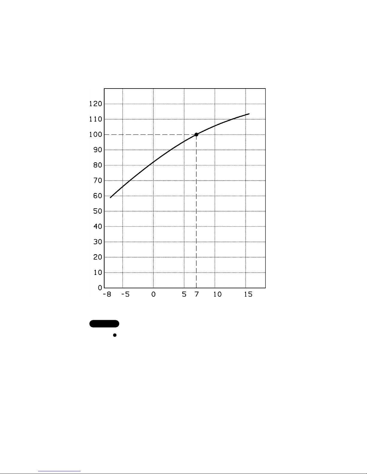
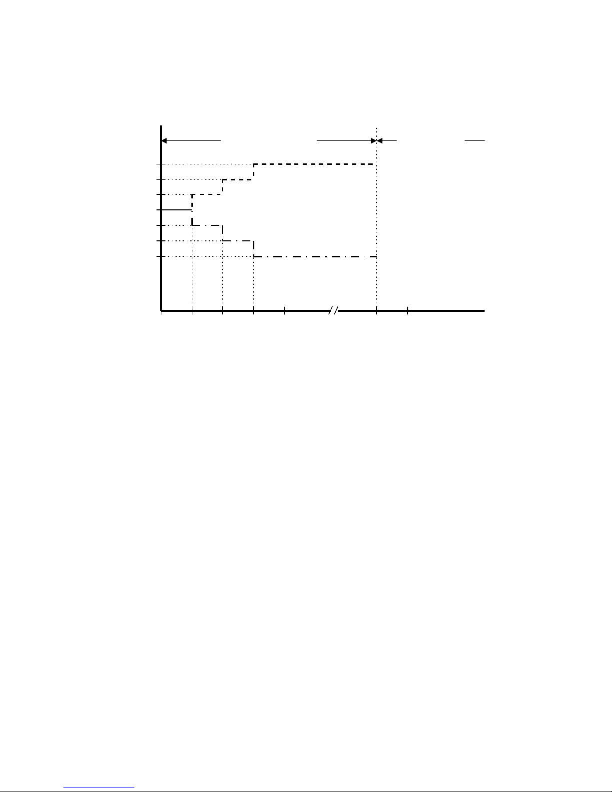
5. HEATING CAPACITY (System A, B or A+B)
Indoor Unit MCA90MR5TAA
Outdoor Unit GR360M4R5TAA
Outdoor temperature (°C DB)
Heating capacity ratio (%)
NOTE
1) … Point of Rating condition
Black dot in the chart indicate the following rating condition.
Indoor : 20°C DB
Outdoor : 7°C DB / 6°C WB
2) Above characteristics take into consideration defrost operation.
3) Fan speed : High
11
Page 16

Indoor Unit MCA90MR5TAA
0
123456789
1
2
3
4
Horizontal distance (m)
Axis air velocity (m/s)
Vertical distance (m)
Axis air velocity
Flap angle
45°
60°
Room air temp. : 20°C
Fan speed : High
Heating
0
123456789
1
2
3
4
Horizontal distance (m)
Axis air velocity (m/s)
Vertical distance (m)
Axis air velocity
Flap angle
0°
30°
Room air temp. : 27°C
Fan speed : High
Cooling
6. AIR THROW DISTANCE CHART
12
Page 17

Wide tube service valve
Narrow tube service valve
Indoor Unit MCA90MR5TAA
Outdoor Unit GR360M4R5TAA
7. REFRIGERANT FLOW DIAGRAM
CIRCUIT A
13
Page 18

Wide tube service valve
Narrow tube service valve
Indoor Unit MCA90MR5TAA
Outdoor Unit GR360M4R5TAA
CIRCUIT B
14
Page 19

8. ELECTRICAL DATA
8-1. Electrical Characteristics
The values in the table below indicate the sum of indoor
units which are in running condition.
NOTE
230V Single phase 50 Hz
Number of indoor unit
1 System 2 Systems
(A1+A2 or B1+B2) (A + B)
Rating Conditions
Running amp. A 9.8 19.6
Power input kW 2.2 4.4
Full Load Conditions
Running amp. A 11.2 22.5
Power input kW 2.55 5.1
230V Single phase 50 Hz
Cooling
Heating
Rating Conditions: Indoor Air Temperature 20°C DB
Outdoor Air Temperature 7°C DB / 6°C WB
Full Load Conditions: Indoor Air Temperature 27°C DB
Outdoor Air Temperature 24°C DB / 18°C WB
Cooling
Heating
Number of indoor unit
1 System 2 Systems
(A1+A2 or B1+B2) (A + B)
Rating Conditions
Running amp. A 10.2 20.4
Power input kW 2.3 4.6
Full Load Conditions
Running amp. A 11.2 22.5
Power input kW 2.55 5.1
15
Indoor Unit MCA90MR5TAA
Outdoor Unit GR360M4R5TAA
Rating Conditions: Indoor Air Temperature 27°C DB / 19°C WB
Outdoor Air Temperature 35°C DB
Full Load Conditions: Indoor Air Temperature 32°C DB / 23°C WB
Outdoor Air Temperature 46°C DB
Page 20
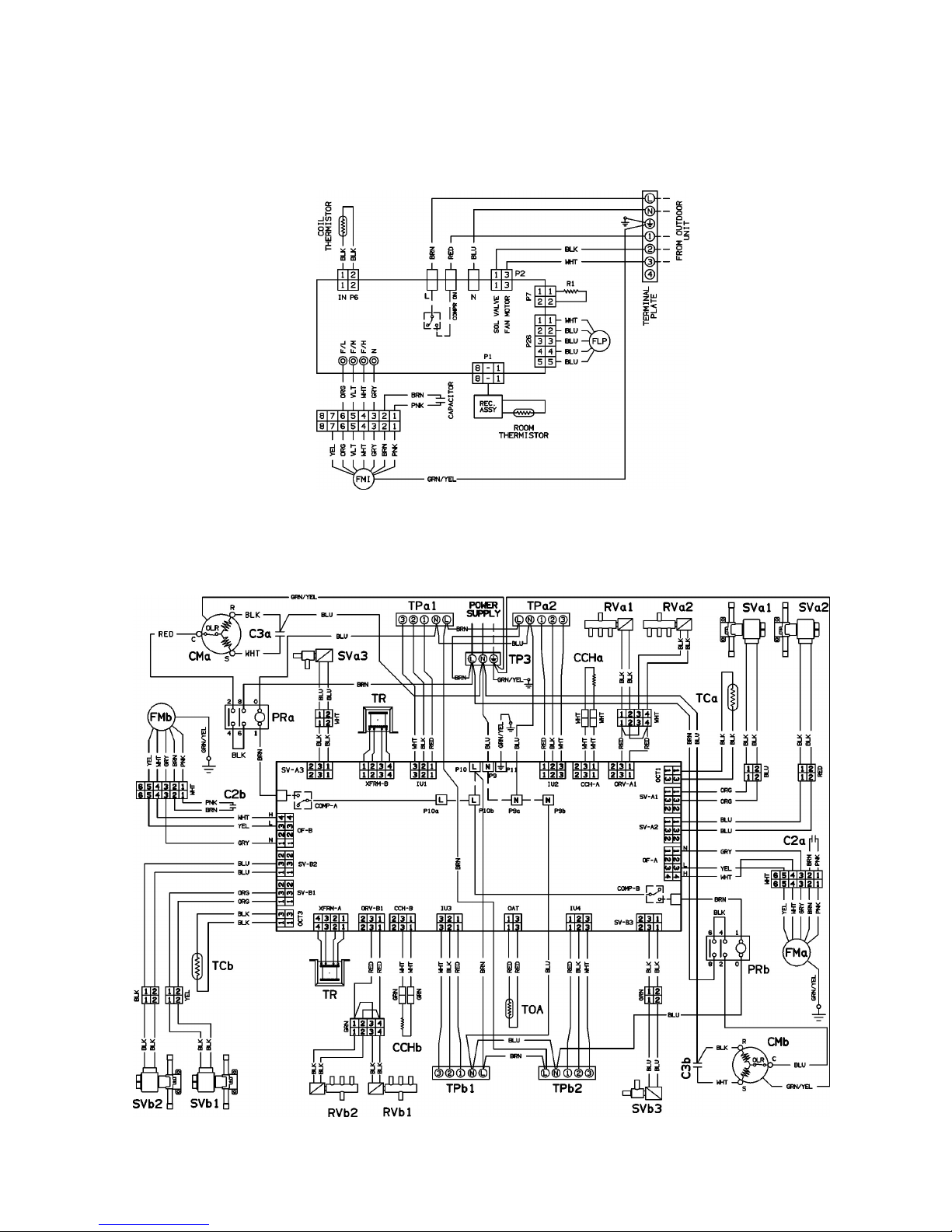
8-2. Electric Wiring Diagrams
Outdoor Unit GR360M4R5TAA
Indoor Unit MCA90MR5TAAA
16
Page 21

9. FUNCTION
9-1 Cool Mode Operation
(RT - SPT) [oc]
+3
+2
+1
0
-1
ON
OFF
ON
OFF
H
L
M
ON
OFF
COMP
OFAN
IFAN
RV
over 3 min over 5 min
over 30 sec
In Cool Mode, the operation of the Compressor (COMP), Outdoor Fan (OFAN) and Indoor Fan (IFAN) are
determined by the difference between the Room Temperature (RT) and the Set Point Temperature (SPT)
as in the graph above.
Notes:
1. In this graph, the IFAN is operating in the “Auto Fan Speed” setting. If the user has selected the low,
medium or high fan speed, the IFAN will run constantly at that speed only.
2. In addition to the value of (RT-SPT), the operations of the relays are also controlled by protection
delays. For example, (a) the minimum On/Off time of the COMP is 5 min and 3 min respectively, and
(b) the IFAN can change speed only after it has operated at the same speed for 30 sec.
17
Page 22

9-2 Heat Mode Operation
(RT - SPT) [oc]
+1
0
-1
-2
-3
H
OFF
L
M
ON
OFF
Note 1 Note 2
COMP
IFAN
RV
ON
OFF
30 sec
The Heat Mode operation is similar to the Cool Mode operation. The COMP, OFAN and IFAN are mainly
controlled by the value of (RT – SPT). In the graph above, the IFAN is operating in Auto Fan speed mode.
Therefore, the IFAN speed changes automatically according to the (RT - SPT).
Note 1: The 30s IFAN operation is for purging the heat from the in-coil after COMP has stopped.
Note 2: The IFAN will not be turned on until the in-coil temperature is high enough (as shown in the graph
below) to prevent the unit from supplying cool air.
In Auto Mode, the unit switches between the
IFAN Speed
Any
Low
Stop
30 35 40
ICT [oc]
ICT = In-coil Temperature
Any = Hi, Med or Low fan speed which is
selected by the user. In Auto Fan Speed
Mode, the fan speed is selected by the
unit automatically instead.
Low = The indoor fan is forced to operate at low
speed
18
Page 23

9-3 Dry Mode Operation
DRY
(RT - SPT) [oc]
+2
+1
0
-1
-2
ON
OFF
LOW
OFF
DRY-ON
DRY-OFF
Time [min]
10
20
30
40 50
COMP
& OFAN
IFAN
5 minutes COMP
ON time
Max 15 minutes Max 15 minutes 6 min
(Note 2)
3.5 min
(Note 1)
In Dry Mode, the unit operates in a mild cool mode to lower the humidity of the room. In order to maintain
a high efficiency in the drying operation without over lowering the room temperature excessively, the Dry
Mode is different from the Cool Mode in two ways.
1. The IFAN is forced to operate at low speed only. And, the IFAN is turned off with the COMP.
2. The unit operates in either the “Dry-on” state or the “Dry-off” state. If RT = SPT, the unit will operate in
“Dry-off” state. The COMP is forced to operate for 6 min after it has stopped working for 15 min. If RT
> SPT, the unit will operate in “Dry-on” state. The COMP is forced off for 3.5 min after it has been
working for 15 min.
Note 1: COMP is forced off in Dry-on state.
Note 2: COMP is forced to operate in Dry-off state.
19
Page 24

9-4 Fan Operation
1. Indoor unit
In Fan Mode the indoor fan is turned on to improve the air circulation in the room. Compressor and
outdoor fan remain OFF all the time.
Note: if the user has selected the Auto Fan Speed setting, the indoor fan speed would be selected by
the unit automatically according to the difference between RT and SPT, as in Cool Mode.
2. Outdoor unit
a. The speed of the Outdoor fans (OFH-A & OFL-A for system A and OFH-B & OFL-B for system B)
can be
• High - OFH is ON, OFL is OFF
• Low - OFH is OFF, OFL is ON
• OFF - both OFH and OFL are OFF
b. The OFH and OFL will never be turned ON at the same time.
c. When the compressor starts working, the speed of the corresponding OFAN is high during the
first 10 min., provided the OFAN is turned ON.
Note:
This rule is not applied at the first compressor starting after an High Pressure Protection (section 9-5).
In this case, the OFAN speed will be determined by the outdoor air thermistor (OAT) as in normal
operation (see below) instead of forced high for 10 minutes. This rule also does not apply when
the outdoor air thermistor is < 21
o
C in cool mode.
d. When compressor is OFF, the corresponding OFAN is forced OFF except during High Pressure
Protection. The OFAN will run at high speed under High Pressure Protection.
e. In general cases, when OFAN is turned ON, its speed (High or Low) is determined by the OAT as
below.
Heat Mode
f. The output of OFAN is low (fan stopped) when -2°C<OCT<8°C provided the HP protection operates
and that the OFAN is turned on (see section 9.6).
Cool Mode
20
Page 25

9-5 Protection Operations in Cool and Dry Modes
1. Indoor Coil Defrost Protection
The in-coil defrost protection can prevent the ice formation at the in-coil when the ambient temperature
is low.
ICT [oc]
+2
ON
OFF
ON
OFF
t1 t2 t3
COMP
OFAN
+1
+5
0
-1
ON
OFF
IFAN
t1 = 5 min minimum for each COMP starting
t2 = OFAN cycling (alternate between ON and OFF every 30 sec) for 20 min maximum
t3 = COMP and OFAN stop for 10 min minimum
21
Page 26

2. Outdoor coil High Pressure Protection
The outdoor coil High Pressure protection prevents the rising of pressure in the outdoor coil
during cool mode operation
Protection INPUTS (from indoor units) OUTPUTS
Condition A
Condition B
RV1
(RV3)
RV2
(RV4)
CO1
(CO3)
CO2
(CO4)
OCT-A
(OCT-B)
ORV-A
(ORV-B)
CO-A
(CO-B)
OF-A
(OF-B)
SV-A1
(SV-B1)
SV-A2
(SV-B2)
SV-A3
(SV-B3)
High Pressure
Protection
Any Any Any Any > 55 RV1
(RV3)
X Hi X X X
Off Off On On = 50 X ON Hi / Lo ON ON X
Termination of Off Off On Off = 50 X ON Hi / Lo ON X ON
HP Protection Off Off Off On = 50 X ON Hi / Lo X ON ON
Notes:
1. Protection Mode is activated when any of the condition A or condition B is satisfied.
• In OCT high pressure protection, only the system that start the protection is under the
control of the protection routine. The other system will continue to work in normal
mode.
2. The OCT HP protection is triggered by the measured OCT-A (or OCT-B) only. The status of the
RV & CO inputs from the indoor units are not checked. This way, the protection can also handle
the abnormal situation caused by hardware failure, such as RV or COM output relay is defective
and
3. If the OF speed is marked as “Hi/Lo”, its speed is governed by the outdoor air thermistor as
explained before.
22
Page 27

9-6 Protection Operations In Heat Mode
1. Outdoor coil De-ice Protection
Protection INPUTS OUTPUTS
Condition A
(Condition B)
RV1
(RV3)
RV2
(RV4)
CO1
(CO3)
CO2
(CO4)
OCT-A
(OCT-B)
ORV-A
(ORV-B)
CO-A
(CO-B)
OF-A
(OF-B)
SV-A1
(SV-B1)
SV-A2
(SV-B2)
SV-A3
(SV-B3)
On Any On On = -2 X ON X ON ON X
Any On On On = -2 X ON X ON ON X
De-icing On Off On Off = -2 X ON X ON X ON
Off On Off On = -2 X ON X X ON ON
On On On On > 12 ON ON Hi / Lo ON ON X
Termination of On Off On Off > 12 ON ON Hi / Lo ON X ON
De-icing Off On Off On > 12 X ON Hi / Lo X ON ON
Notes:
1. Protection Mode is activated when any of the condition A or condition B is satisfied.
• In De-icing mode, both systems (A & B) will always perform De-icing at the same time.
2. In the de-icing process:
(i) The de-icing process can be triggered by any one of the OCT which is < -2
o
C with the
corresponding COMP, RV are both ON and de-icing timer counts to zero.
(ii) The de-icing timer is stopped (the count is reserved) when both COM-A and COM-B
are OFF.
(iii) The de-icing timer counts down when any of the compressor turn on.
(iv) The de-icing timer is reset (to maximum count) when the condition “RV output of the
IDU are all Off or all OCT > -2
o
C” .
3. If the OF speed is marked as “Hi/Lo”, its speed is governed by the outdoor air thermistor as
explained before.
23
Page 28

2. Outdoor Coil High Pressure Protection in Heat Mode
The outdoor coil high pressure protection prevent the rising of pressure in the circuit during heating
operation at high evaporating temperatures.
24
Page 29
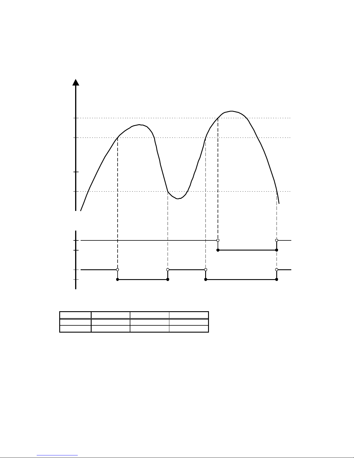
3. Indoor Coil High Pressure Protection in Heat Mode
The in-coil high pressure protection prevent the build up of high pressure at the in-coil during heating
operation.
Note:
The operation temperatures shown as A and B in the chart differ by models.
MCA90MR5
A 54 - B 45 - -
ICT [oc]
ANY
OFF
ANY
COMP
OFAN
B
A
64
OFF
COMP is forced OFF
25
Page 30

9-7 Cold Draft Prevention (Heating)
• This function controls indoor fan speed so a strong draft of cold air will not blow out before the indoor heat
exchange coil have sufficiently warmed up.
• When 10 minutes has elapsed, the fan speed is automatically switched to set speed regardless of indoor heat
exchange coil temperature.
Indoor heat exchange
coil temp. (°C)
Max.10 minutes
Tc
Indoor Fan OFF Set Speed
NOTE
• The operation temperature shown as Tc in the chart differ by models.
MCA90MR5
Tc 32
26
Page 31
9-8.1 Sleep Function
Room temperature is automatically controlled to compensate for body temperature variations while
sleeping. This mode of operation is designed for maximal comfort in both COOL and HEAT modes.
SPT
Time [Hr]
432
Start
Sleep
7 - 12
RT
SPT-1
SPT-2
SPT-3
SPT+2
SPT+1
SPT+3
1
7-12 Hours Sleep operation
Unit is turned to SB
after Sleep
Cool, Dry modes
Heat mode
9-8.2 Daily Timer Function
Unit can be programmed to be ON and OFF automatically at preset time everyday, by using a remote
controller. The resolutions of the ON/OFF timers are 10 min.
9-8.3 IFEEL Function
This feature is provided if the unit is used together with a remote controller with the I-FEEL function. When
this function is selected, the remote controller sends the room temperature measured by its build-in
thermistor to the air con for more accurate temperature control.
9-8.4 Louver Control
The airflow louver can be driven by either a 12V DC stepping motor or an AC motor. The louver can be
set to operate at auto swing mode or fix position mode.
Three additional features are provided if the louver is controlled by a DC stepping motor.
• Different swing positions (range) for Heat Mode and Cool Mode operation
• Last louver position in fix position mode is stored in the EEPROM, and is restored when the unit is
turned on.
• The louver is closed automatically when the unit is switched to standby mode.
27
Page 32

The push button switch and the LED indicators on the display panel let the user to control the unit
operation without a remote controller. Their operations are provided below.
STAND BY
INDICATOR
1. Lights up when the Air Conditioner is connected to power and
ready to receive the R/C commands
2. Blinks continuously in case of any thermistor failure.
OPERATION
INDICATOR
1. Lights up in operation mode (Note: OFF in standby mode).
2. Blinks for 0.5 sec., to announce that a R/C infrared signal has
been received and stored.
3. Blinks continuously during
• OCT High Pressure Protection Mode
• Deicing in Heating Mode
TIMER INDICATOR
1. Lights up during Timer and Sleep operation.
2. Active On/Off timer setting will become invalid after a power
failure. When this happens, the unit is forced to restart in STBY
mode, and the Timer Indicator is blinked continuously until (i) the
unit is switched to OPER Mode again, or (ii) any message from
the R/C is received.
Push Button switches:
MODE BUTTON
(Cool, Heat, SB)
Use to cycle the operation mode of the A/C unit among COOL,
HEAT and SB modes, without using the R/C.
Every time this switch is pressed, the next operation mode is
selected, in the order :
SB => Cool Mode => Heat Mode => SB => ...
28
9-8.5 Manual Unit Control and LED indicators
1. Indoor Unit PCB
2. Outdoor Unit PCB
The status of the Multi Split Controller system (MSC) is indicated by a system Status LED and a Power
LED on the control board of the outdoor unit. The Power LED will be ON whenever there is +5V
supply voltage in the system, otherwise it is OFF. In addition, only the Status LED will be
controlled by the microprocessor (MCU) to indicate its internal operational status. The leds’ operation
details can be described by the following table.
Conditions Power LED L3 (Green) Status LED L2 (Red)
Normal Operation ON OFF
Self test in progress ON ON
Self test completed w/o
error
ON Blink at 10Hz for 3sec,
then OFF
Fault Detected
(in operation or test mode)
ON Blinking
(see note below)
Power OFF / no power OFF OFF
Notes:
1. When any fault is detected, the most significant digit of the error code is shown by
using the blinking Status LED. For example, when one of the thermistors is not
operating properly, the Status LED will be blinking with the pattern “Blink 5 times ->
OFF for 2 sec -> Blink 5 times -> …” so as to indicate that an error code of 5 has
been detected (see section related to fault detection for more information).
Page 33

9-8.6. Fault Operations and Indications (Outdoor Unit PCB)
The MCU of the MSC system will monitor all input continuously. Then update the status of the inputs
every second. To prevent temporary input error from interfering with normal operation, the MCU will
not take immediately action when an error is detected. In general, the MCU will regard an input as
defective only if four successive invalid data are received at that input. As a result, there will be a 2
seconds delay between the occurrence of an error and the MCU makes proper response to this error.
1. Fault Conditions in Operating Mode
Fault operations can be one or more of the following:
• The zero crossing circuit is not working at the frequency of 90-132 Hz
• The OAT thermistor is not functional (Temp < -30oC or Temp > 75oC)
• Any of the OCT thermistor is not functional, that is:
measured OCT is out of operational range: Temp < -30
o
C or Temp > 95oC
• Any of the +12V DC supply voltage is under 8V DC.
• Any photo-coupler output of an enabled indoor unit is invalid
2. Fault Handling
Beside blinking the system Status LED, the MSC MCU will also response to the system faults by
taking different preventive actions to protect the system hardware.
(1) The MSC MCU will turn OFF all outputs of both systems in case of critical fault condition, one
example is:
• the zero crossing circuit is not working at the frequency 90-132 Hz.
(2) The MSC MCU will turn OFF the outputs of a system in case of local fault
• the +12V DC supply voltage of that system is under 8V DC
Note : If the +12V DC supply voltage of both systems is under 8V DC, the MCU will turn OFF
all relays, and suspend all relay operations. When one or both DC supply voltage is
back to normal, the MCU will perform a “System Reset” function.
(3) The MSC unit will disable a specific indoor unit, when
• the OCT thermistor of this unit is not functional
• any photo-coupler output of this unit is faulty
(4) The MSC unit will always select the High OFAN speed if the OFAN is turned ON, when
• OAT failure occurs
Note:
A failed input, such as thermistor or photo-coupler, can be recovered whenever 4 successive valid
inputs (2 sec) are received.
29
Page 34
3. Self Test
Self test is initiated by connecting J1 jumper and 3 fixed resistors of 10k 1/4W, 5% or thermistors at
OCT1, OCT3 and OAT satisfying conditions in note1, then H/W reset the unit. The J1 must be
connected throughout the test operations. Otherwise, the system will go back to normal operation
mode. Moreover, all Indoor Units must be in STBY mode to prevent the Indoor Unit operations from
interfering with the test procedure.
3.1 Self Test Procedure
No Step
Task Description / Work
Element
Observations on UUT
1 Initiate the Self
Test under
internal loop-back
1.1 Power up the UUT by
connecting Line-In on P10 and
Neutral P9
-
1.2 The following tests is
proceeded automatically:
- Relay Walk Test
- Zerocrossing frequency test
- 12VDC supply test
- EEPROM test
- Watchdog Reset timing test
- Thermistors test
- Auto Input Test
Wait for 8-10 seconds.
Each output of UUT is turned ON
for 2 sec with a 0.5 sec
separation in the order below:
CCH-A,ORV-A,COM-A,SVA1,SV-A2,SV-A3,OFH-A,OFL-A
CCH-B, ORV-B,COM-B,SVB1,SV-B2,SV-B3,OFH-B,OFLB,HE
1.3 Self test completed All relays are turned OFF.
If no error is detected, the Red
LED on UUT is blinked at 10 Hz
frequency for 3 sec and then
turned OFF.
If error is detected, the error
code is shown in the Red LED by
a flash pattern as indicated on
section 7.2
2 Initiate the Self
test under
external loop
back
2.1 Disconnect the power to the
UUT
2.2 Connect the Testplug at TP1,
which is also linked to IU1,
IU2, IU3 and IU4, on the UUT
2.3 Provide 220VAC signal inputs
to all photo-coupler
2.4 Repeat procedure 1.1 to 1.3
Note1: 1.The 3 thermistors must be within operation range.
2.The difference among the 2 OCTs must be less than 5°C.
3
.The maximum difference between the OAT and any OCT must be less than 5°C.
30
Page 35

4. Error Code Message
Display of Error Code: Indicated by the Status LED (Red color), a flash pattern consists of 1 to 6
flashes with 0.5sec separation, which is corresponding to the error code 1 to 6. The flash pattern is
repeated continuously with 2sec separation.
No of Flashes
(Error Code)
Error Message
1 Zero Crossing Test Fails
The frequency of the zero-crossing input is measured. To pass this test,
the frequency must be in the range of [90, 132] Hz.
2 12V DC Supplies Test Fails
The output levels of the two 12V DC supplies are measured. To pass this
test, the supply voltages must be over 8V.
3 EEPROM Test Fails
All locations in the EEPROM is tested by non-destructive Read, Write
and Verify.
4
Watchdog Reset Timing Test Fails
The Watchdog output from the MCU is stopped. And the time taken by
the external reset circuit to generate a Hardware Reset is measured.
Criteria to pass: the reset must be generated between 1 to 4 sec after the
Watchdog signal is stopped.
5 Thermistors Test Fails
The temperature detected by the 2 thermistors are compared with each
other.
Criteria to pass: the thermistor outputs must be within operational range
and the maximum difference between the OAT and any OCT must be
less than 5
o
C
6 Auto Input Test Fails
Each input from the photo-coupler is tested with Testplug or without
Testplug
- With Testplug, all input should provide 220VAC
- Without Testplug, all input should have no 220VAC
5. Jumper Settings
5.1 Self-test jumper - J1 (Factory test)
The J1 is used to switch the Outdoor unit to self-test mode. To do so, J1 must be closed before
switching ON the power of the unit. The J1 must be closed during the tests. Whenever J1 is
disconnected, the unit will go back to normal operation mode.
Operation Mode J1 setting
Self Test Closed
Normal Operation Open
31
Page 36

5.2 Quick Test jumper – J2 (Assembly test)
The jumper J2 is used to speed up the operation mode by 60.
Operation Mode J2 setting
Quick Test Closed
Normal Operation Open
9-8.7 Recovery from Power Failure (Indoor Unit PCB)
Last unit settings (SPT, operation mode, louver settings, etc) are saved in the EEPROM in the unit. In
case of power failure, these settings are restored automatically.
32
Page 37

10. TROUBLESHOOTING
10-1. Check before and after troubleshooting.
10-1-1. Check power supply wiring.
●
Check that power supply wires are correctly connected to terminals No. 1 and No. 2 on the 3P terminal plate in
the outdoor unit.
10-1-2. Check inter-unit wiring.
●
Check that inter-unit wiring is correctly connected to the indoor units from the outdoor unit.
10-1-3. Check power supply.
●
Check that voltage is in specified range (±10% of the rating).
●
Check that power is being supplied.
10-1-4. Check lead wires and connectors.
●
Check that coating of lead wires is not damaged.
●
Check that lead wires and connectors are firmly connected.
●
Check that wiring is correct.
WARNING
Hazardous voltage can cause ELECTRIC SHOCK or DEATH.
Disconnect power or turn off circuit breaker before you start
checking or servicing.
33
Page 38

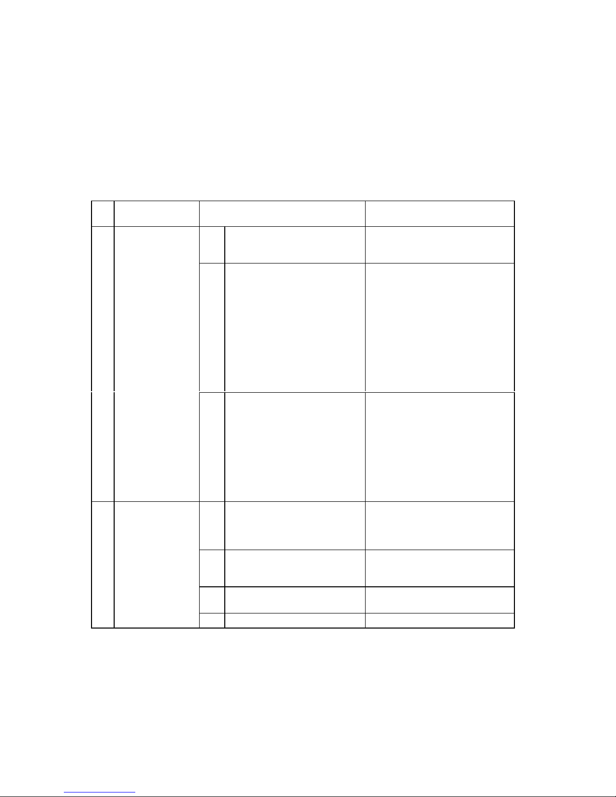
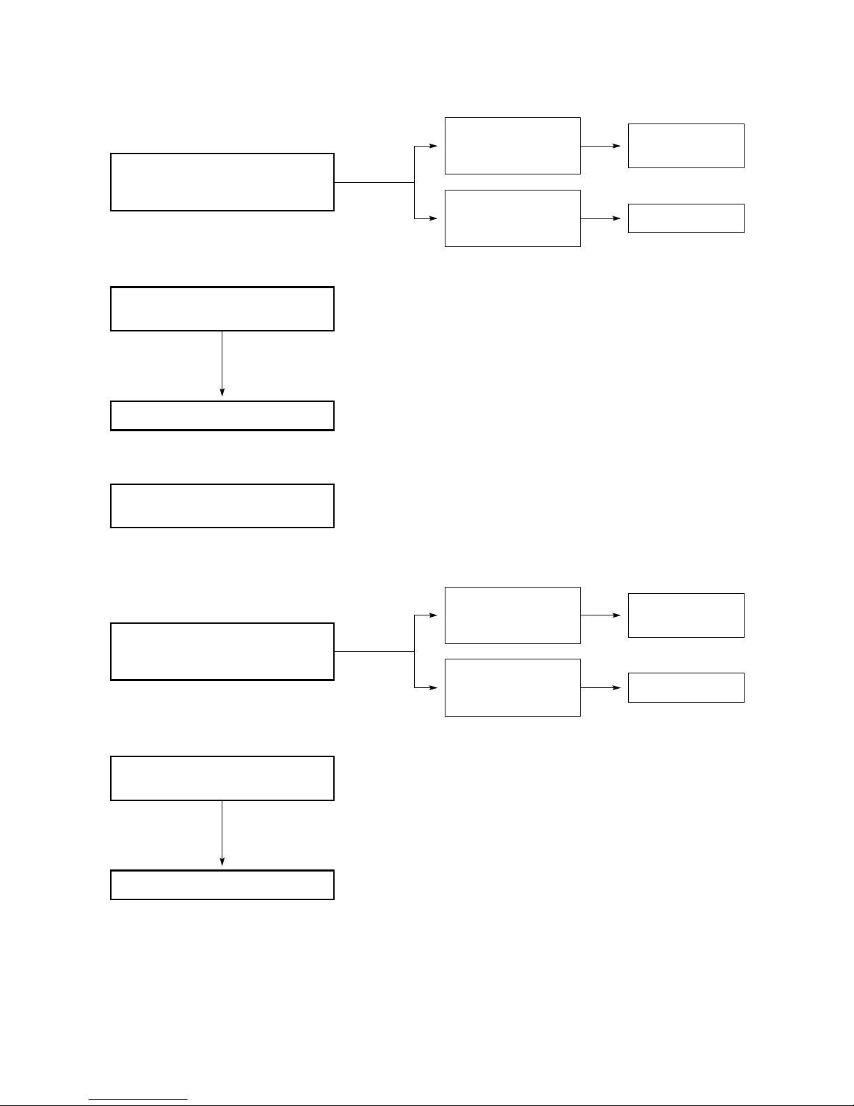
10-2. Air conditioner does not operate.
10-2-1. Circuit breaker trips (or fuse blows).
A. When the circuit breaker is set to ON, it is tripped soon. (Resetting is not possible.)
●
There is a possibility of ground fault.
●
Check insulation resistance.
If resistance value is 1MΩ or less, insulation is defective (“NO”).
B. Circuit breaker trips in several minutes after turning the air conditioner on.
●
There is a possibility of short circuit.
Measure insulation
resistance of electrical
parts in outdoor unit.
NO
NO
Set circuit breaker to OFF.
*
Measure insulation
resistance of electrical
parts in indoor unit.
1
Remove both power supply wires
and inter-unit wires from terminal
plate in outdoor unit.
Measure insulation resistance
of outdoor unit.
•
2
Remove inter-unit wires from
terminal plate in indoor unit.
Measure insulation resistance
of indoor unit.
•
•
•
Insulation of
outdoor unit
is defective.
Insulation of
indoor unit
is defective.
Check capacity of circuit breaker.
Capacity of circuit breaker is
suitable.
Replace with suitable
one (larger capacity).
•
Measure resistance of compressor
motor winding. (CMa, CMb)
•
Measure resistance of outdoor fan
motor winding. (FM)
•
NO
34
Page 39
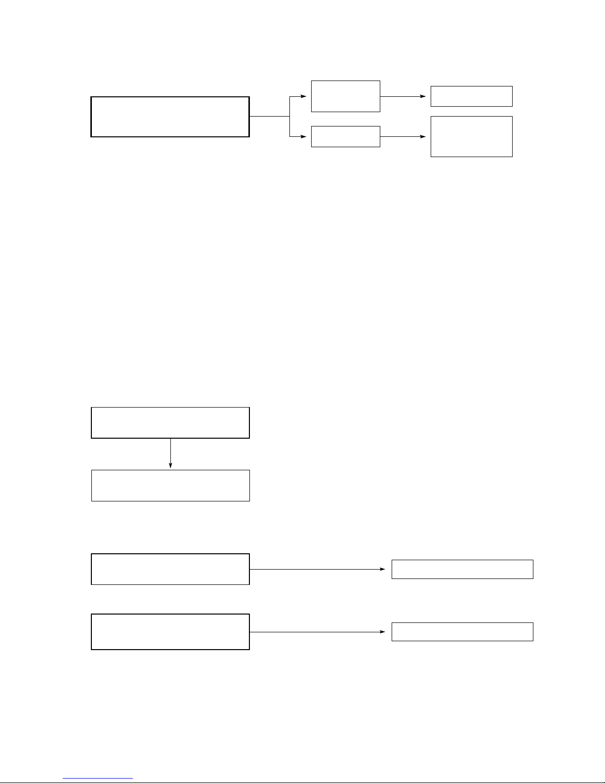
10 -2-2.Neither indoor nor outdoor unit runs.
A. Power is not supplied.
B. Check remote control unit.
NO
•
Check power supply.
Power is being supplied to the
outdoor unit.
Circuit breaker
is tripped.
Power failure
Reset breaker.
Wait for recovery
or contact power
company.
OK
•
Try to run with another remote
control unit.
First remote control unit is defective.
•
Check for residue buildup on
transmitter of remote control unit.
•
Check for residue buildup on remote
control receiver on front of indoor
unit.
Clean transmitter.
Clean receiver.
35
Page 40

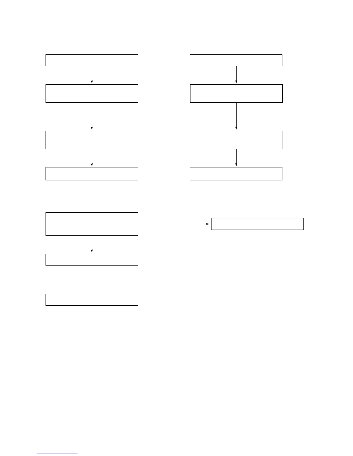
C. Check fuse on the indoor PCB Ass'y.
OK
Replace the fuse.
OK
OK
•
Check fuse on indoor PCB Ass'y
for continuity.
•
Check operation lamp to see
if light is ON.
Light is OFF
•
Measure resistance of primary and
secondary winding of transformer.
(TR)
Indoor PCB Ass'y or switch Ass'y is
defective.
OK
•
Measure resistance of indoor fan
motor winding.
(FMI)
•
Measure resistance of flap motor
winding. (FLP)
If fuse has been blown,
E. Check TIMER button on the remote control unit.
•
Timer is turned ON. Check to see
if "ON" is displayed on remote
control
YES
Press CLEAR button to cancel
the timer mode.
D. Check fuse on the outdoor PCB Ass'y.
OK
OK
OK
•
Check fuse on outdoor PCB Ass'y
for continuity.
•
Check operation led (L3 green) to see
if light is ON.
Light is OFF
•
Measure resistance of primary and
secondary winding of transformer.
(TR)
Indoor PCB Ass'y is defective.
OK
•
Measure resistance of outdoor fan
motor winding.
(FMa, FMb)
•
Measure resistance of solenoid valves
(SVa/b, RVa/b)
If fuse has been blown,
•
Measure resistance of crank case
heaters and power relays.
(CCHa, CCHb, PRa, PRb)
OK
Replace the fuse.
36
Page 41
10-2-3.Only outdoor unit does not run.
A. Check setting temperature.
B. Check PCB Ass'y in either indoor or outdoor unit.
12-2-4.Only indoor unit does not run.
OK
NO
Is room temperature too low ?
Try to lower setting temperature by
temperature setting button cooler.
Outdoor unit still does
not run.
Remote control unit is defective.
•
Try to run using another remote
control unit.
COOL
OK
NO
Is room temperature too high ?
Try to raise setting temperature by
temperature setting button warmer.
Outdoor unit still does
not run.
Remote control unit is defective.
•
Try to run using another remote
control unit.
HEAT
•
Indoor PCB Ass'y is defective.
•
Check voltage between terminals No.1
and N at terminal plate of indoor unit.
(AC 220V)
No voltage appears.
•
Outdoor PCB Ass'y is defective.
OK
•
Indoor PCB Ass'y is defective.
37
Page 42
10 -3. Some part of air conditioner does not operate.
10-3-1.Only indoor fan does not run.
10-3-2.Only flap motor does not run.
10-3-3.Only outdoor fan does not run.
Fan cannot
be turned.
OK
•
Check fan rotation.
Turn fan gently once or twice by
hand.
•
Check fan casing
foreign matter on
inside.
Fan motor burnout
or foreign matter in
bearings.
Remove foreign
matter or repair.
Repair or replace.
•
Measure resistance of indoor fan
motor winding.
•
Check fan motor capacitor.
Fan cannot
be turned.
Check fan casing
for foreign matter
on inside.
Check fan rotation.
Turn fan gently once or twice
by hand.
•
Measure resistance of outdoor fan
motor winding.
•
OK
•
Fan motor burnout
or foreign matter
in bearings.
Repair or replace.
Remove foreign
matter or repair.
Check fan motor capacitor.
•
•
Measure resistance of flap motor
winding.
38
Page 43

10-3-4.Only compressor does not run.
Measure resistance of
compressor motor winding.
•
NO
Check compressor motor
capacitor.
•
YES
YES
YES
Overload relay is working.
Refrigerant gas shortage. Charge refrigerant gas (R22).
Temperature of compressor is
abnormally high.
Rotor may be locked up.
(OLR)(C3a,C3b)
Measure coil resistance of
power relay. (PRa,PRb)
39
Page 44
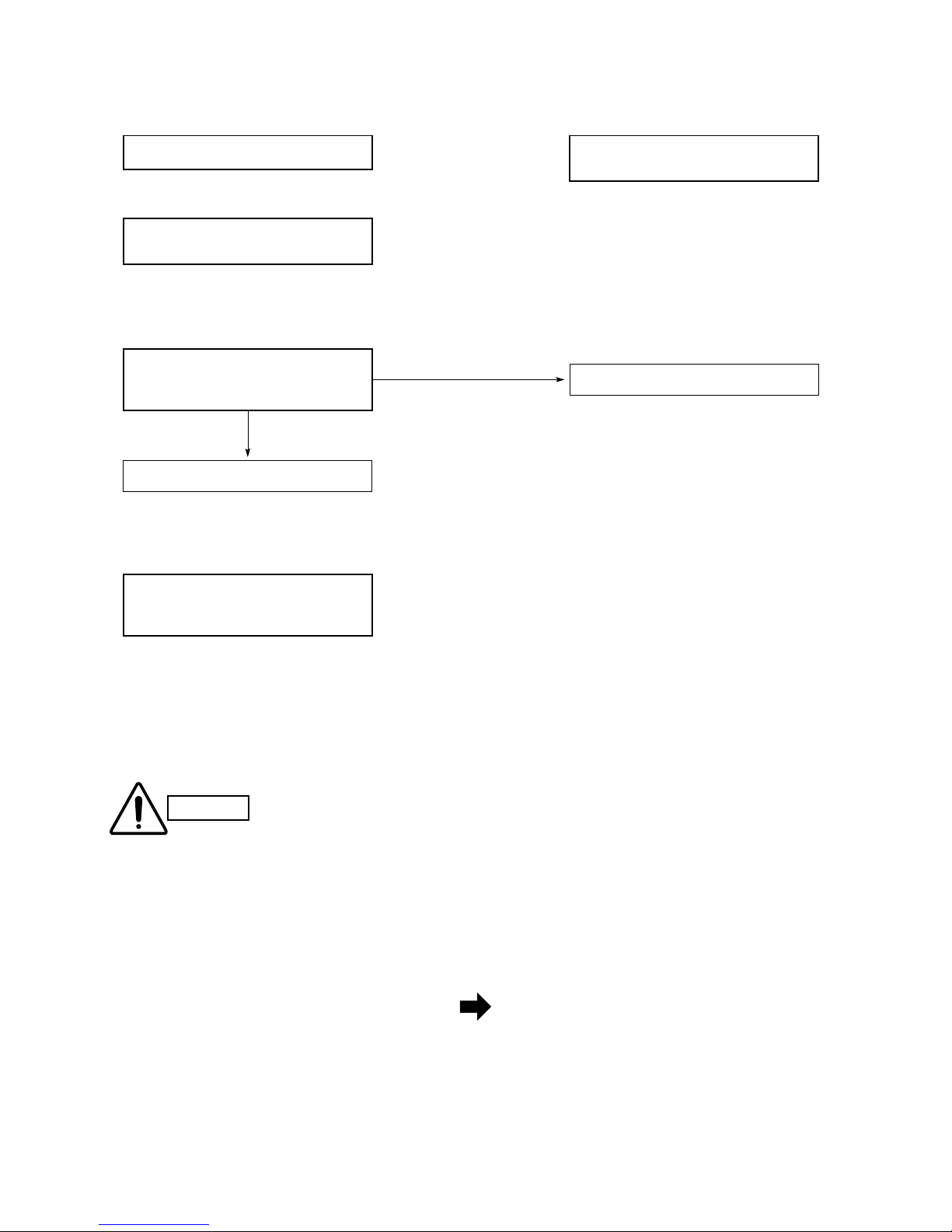
10 -4. Air conditioner operates, but abnormalities are observed.
12-4-1.Operation does not switch from HEAT to COOL (or COOL to HEAT).
•
Indoor PCB Ass'y is defective.
•
Check voltage between terminals
No. 2 and N at terminal plate.
(AC 220V)
No voltage appears.
Outdoor PCB Ass'y is defective.
OK
•
Remote control unit may be defective.
•
Measure resistance of 4–way valve's
winding.
Receiver in switch Ass'y may be
defective.
COOL ➞ HEAT
•
Check voltage between terminals
No. 2 and N at terminal plate.
(0V)
HEAT ➞ COOL
When unit a1 stops unit a2 will switch to cooling or drying operation.
Unit a1 in heating mode (first unit switched)
Unit a2 in cooling or drying mode
Unit a1 in heating mode.
Heating operation has precedence so unit a2 is
in stand-by mode.
• If, in one system ( A for example), the units tried to be operated in different modes (unit a1 in heating while unit a2
in cooling), the results are as follows:
Units of one system (A or B) cannot operate in different modes simultaneously (for
example unit a1 operating in the heating mode while unit a2 is in the cooling one).
When operating two units of the same system, set them both to the same mode.
Different system instead, can operate in different mode that is system A can be in
cooling mode while B in the heating one.
CAUTION
40
Page 45

10-4-2.Poor cooling or heating.
10-4-3.Excessive cooling or heating.
Air filter is clogged.
NO
YES
Temperature
difference
is small.
YES
Temperature difference between
suction and discharge air is
large enough (approx. 10 deg. or more).
Possibility of
gas shortage.
YES
•
Check position of remote control unit.
Cool or warm air from air conditioner
reaches position directly.
•
Change position of remote
control unit.
•
Wide and narrow tubes between
indoor unit and outdoor unit are
insulated.
Insulate both wide and narrow
tubes separately and then
tape together.
•
Measure temperature of suction and
discharge air of air conditioner.
Charge refrigerant
gas (R22).
Check for clogging of air filter.
•
Fan speed is set to LOW.
Clean filter.
Set fan speed to either
HIGH or MEDIUM.
•
Review cooling load estimate,
if performance of air conditioner is
normal.
Reduce cooling or heating
load or replace the air
conditioner with larger
capacity.
NOTE
NO
NO
•
Set temperature is suitable.
Set temperature to higher or
lower value using temperature
setting buttons of the remote
control unit.
•
Remote control unit is placed where
it can detect room temperature
properly.
Change position of remote
control unit.
41
Page 46

10-5. If a sensor is defective.
10-5-1.Indoor coil / room temperature thermistor is defective.
•
Stand-by lamp on front side of
indoor unit is flashing on and off.
YES
•
Replace thermistor(s).
•
At least one of the thermistors is
defective (that is, SHORT or OPEN.)
Temperature
sensor
Lead
wires
Thermistor Structure
10-5-2.Outdoor coil / outdoor air temperature thermistor is defective.
•
Status led (RED) on outdoor PCB
blinks 5 times then off (repeat)
YES
•
Replace thermistor(s).
•
At least one of the thermistors is
defective (that is, SHORT or OPEN.)
Definition of Open or Short Circuit of Sensor (Thermistor)
Open...A lead wire is broken or disconnected or the circuit inside the temperature sensor is open .
Short...The protective cover of a lead wire has been damaged, and the exposed wire is touching another metal
part, or both lead wires have become exposed and are touching each other. Alternatively, the circuit inside
the temperature sensor is closed.
NOTE
42
Page 47

11.ARRANGEMENT OF ELECTRICAL COMPONENTS
Terminal Plate
Outdoor Unit GR360M4R5TAA
43
Page 48

Outdoor Unit GR360M4R5TAA
Parts Layout in Unit
44
Page 49

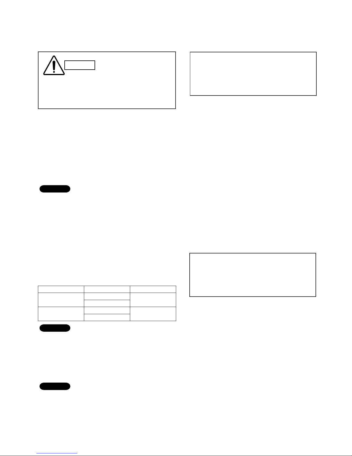
IMPORTANT!
For your personal safety, be sure to read
and understand the following precautions
before servicing.
●
To avoid risk of injury when servicing the outdoor unit
(for instance, when replacing the compressor or
repairing a refrigerant leak), follow the procedure
12-1-1. Confirm mains power is switched OFF, then
open the electrical box in order to access to
the Power Control Board (PCB).
IMPORTANT!
Always check for fan running during the
servicing. This ensure you that the solenoid
valves SVa1 and SVa3 are open.
12. SPECIAL PRECAUTIONS WHEN SERVICING THE UNIT
Injuries can occur from burns or inhalation of
toxic gas if servicing is performed while
refrigerant remains in the refrigeration circuit.
This servicing includes disassembling brazed
tubing connections and removing any
refrigeration parts or components.
WARNING
Fig.12-1
Fig.12-2
The following procedures are outlined as if SYSTEM A
has to be serviced. The same steps, obviously, applies
in case of SYSTEM B servicing.
NOTE
12-1-2. Disconnect the brown wire from the terminal
of PCB's compressor relay. (Fig.12-1)
12-1-3. Connect two wires between poles L, 1, and 3
of the terminal plate (Fig.12-2)
Supply power to the outdoor unit. After 3 minutes
the outdoor fan A will start running and the solenoid
valves SVa1 and Sva3 will open.
In some cases it is required to have solenoid valves opened
during servicing. When so, perform the following steps:
45
Page 50
12-2. Refrigerant recovery
12-2-1. Open the service valve to recover refrigerant into
refrigerant recovery unit.
12-3. Service on outdoor unit
12-3-1. After making sure that the refrigerant in the
circuit has been completely discharged, perform
the required servicing, such as replacing the
compressor or repairing refrigerant leaks.
12-3-2. Before going on to the next step, leak test all
joints where welding has been done.
Nitrogen gas is best when pressurizing the system
for a leak test. However, if it is necessary to instead
test with refrigerant gas, be sure to recover all gas
into the refrigerant recovery unit after completing
the leak test.
12-4. Evacuation using vacuum pump
12-4-1. Using a hex wrench, set the valve stems of both
the narrow and wide tube service valves as
indicated in table below.
Refer to " Service Valve Construction "shown later
12-4-2. Connect the vacuum pump and a manifold valve
as shown in Fig.12-3.
Confirm that all connections are correctly made.
In order to withstand negative suction pressure
during evacuation, the manifold valve should be
equipped with a Hi/ Lo compound gauge with a
minimum scale reading of -76
cmHg.
NOTE
NOTE
NOTE
Refrigerant released into the air contributes to
destruction of our planet's ozone layer. You
should always use the refrigerant recovery unit
to help protect the environment.
CAUTION
Service Valve Valve Position
Unit A 1
Narrow
Wide
Unit A2
Narrow
position -a-
Wide
IMPORTANT!
This procedure requires solenoid valves
opening during the operation. Follow the
steps of 12.1 before starting.
position -c-
IMPORTANT!
This procedure requires solenoid valves
opening during the operation. Follow the
steps of 12.1 before starting.
46
Page 51

12-4-3. Install (first by hand-tightening, then securely with
a wrench) flare nuts and bonnets at all service
valves in the refrigeration circuit where evacuation
will take place. This process is highly important
to completely evacuate the system.
12-4-4. With the " Lo " and "Hi" knobs of the manifold valve
open run the vacuum pump. The operation time
varies with the capacity of the pump.
Evacuation is successful if the vacuum gauge
reading remains –75 cmHg or more for at least 10
seconds after closing the " Lo " and "Hi" knobs of
the manifold valve.
12-4-5. With the vacuum pump still running, turn the wide
and narrow service valves all the way in order to close
them (position -a-).
Stop the pump.
12-4-6. After removing the vacuum hoses from the service
valves, replace the flare nuts and bonnets on the
valves. The refrigerant circuit is now ready for
charging.
12-5. Refrigerant charging
12-5-1. After evacuation is completed, charge the circuit
with the proper amount of refrigerant.
The proper amount of refrigerant is specified on
the nameplate of the outdoor unit and in Section
"2-1. Unit Specifications" in the service manual.
12-5-2. Use a hose to connect the narrow tube service
valve to the liquid port of the charging cylinder.
(Fig.12-4 )
12-5-3. Purge air from the hose. Do this by opening the
charging cylinder valve, then slightly loosening the
connection to the narrow tube service valve. Wait
a few moments, then retighten the connection.
NOTE
Fig. 12-3
Fig. 12-4
47
Page 52

12-5-4. With a hex wrench, open the service valve little
by little to let refrigerant enter the circuit.
(Figs.12-4 )
●
Write down the gradation levels on the charging
cylinder before and after the charging. This allows
you to calculate the charging volume.
12-5-5. If it is not possible to completely charge the unit
with the proper amount of refrigerant, an additional
charging can be made after installing the units.
In this case after re-setting the outdoor unit to the
normal state (see 12-6), the charge is done using the
wide valve port with the system running in COOLING
12-6. Reset the unit for normal operation
12-6-1. Turn off the power source.
12-6-2. Connect the brown wire to the relay terminal as
it was before servicing. (Fig.12-5 )
NOTE
Charging
volume
Gradation
level before
charging
Gradation
level after
charging
=
–
NOTE
Reset always the unit as it was before servicing.
Otherwise the system will not perform correctly
and damage may occur.
CAUTION
12-6-3. Remove the servicing wires from the terminal
plate. (Fig.12-6 )
Fig.12-5
Fig.12-6
When servicing has finished, the outdoor unit must be set to
the normal operation state. In this case do the following:
mode.
Charging the unit with a large amount of
refrigerant at once may damage the compressor.
Always charge the unit at a constant charging rate
of about 100g.
48
Page 53

■
Service Valve Construction
●
Valve Position -a-
The valve stems of both the wide and narrow tubes
are turned all the way in. The unit is shipped from the
factory in this position. (Fig.12-7a)
●
Valve Position -b-
The valve stems of both the wide and narrow tubes
are turned all the way out ("BACK SEAT" position).
This is the normal operating position. (Fig.12-7b)
●
Valve Position -c-
With the narrow tube valve kept at BACK SEAT, only
the wide tube valve stem is turned to the halfwaydown position. This position is used when refrigerant
circuit evacuation is required from both narrow and
wide tube valves at the same time. This position is
also used when additional refrigerant charging is
required in the field with both the indoor and outdoor
units installed.(Fig.12-7c)
●
Valve Position -d-
With the valve stem of the wide tube turned all the way
in, only the narrow tube valve stem is turned to the
halfway-down position. This position is used for
refrigerant charging for only the outdoor unit.
(Fig.12-7d).
When opening or closing the
service valve stem, use the
supplied accessory hex
wrench. Be sure to fully seat
the wrench before turning the
valve.
CAUTION
• Condition at Evacuation
• Condition at Charging
in the Field.(-c-)
• Condition at Charging
with Only Outdoor Unit (-d-)
• Condition at Operation (-b-)
• Condition at Shipping (-a-)
Valve cap
Stem
O-ring
Fig.12-7d
Fig.12-7c
Fig.12-7b
Fig.12-7a
Wide Tube Narrow Tube
Close
Hex
wrench
Open
49
Page 54

13-1. Measurement of Insulation
Resistance
●
The insulation is in good condition if the resistance
exceeds 2MΩ.
13-1-1. Power Supply Wires
Clamp the ground wire of the power supply wires with
the lead clip of the insulation resistance tester and measure the resistance by placing a probe on either of the
power wires. (Fig. 1)
Then measure the resistance between the ground wire
and the other power wire. (Fig. 1)
13-1-2. Indoor Unit
Clamp an aluminum plate fin or copper tube with the lead
clip of the insulation resistance tester and measure the
resistance by placing a probe on each terminal screw
except where the ground line is connected on the terminal plate. (Fig. 2)
13-1-3. Outdoor Unit
Clamp a metallic part of the unit with the lead clip of the
insulation resistance tester and measure the resistance
by placing a probe on each terminal screw where power
supply lines are connected on the terminal plate. (Fig. 2)
13-1-4. Measurement of Insulation
Resistance for Electrical Parts
Disconnect the lead wires of the desired electric part
from terminal plate, capacitor, etc. Similarly disconnect
the connector. Then measure the insulation resistance.
(Figs. 1 to 4)
Refer to Electric Wiring Diagram.
If the probe cannot enter the poles because the hole is
too narrow then use a probe with a thinner pin.
Insulation
tester
Probe
Clip
Ground wire
Fig. 1
Terminal plate
Copper
tube or
metallic part
Clip
Insulation
tester
Probe
Fig. 2
Copper
tube or
metallic part
Clip
Insulation
tester
Probe
Fig. 3
Clip
Insulation
tester
Probe
Metallic
part
From fan motor,
compressor and
other parts
Fig. 4
13. CHECKING ELECTRICAL COMPONENTS
NOTE
50
Page 55

13-2. Checking continuity of Fuse on
PCB Ass'y
●
Check for continuity using a multimeter as shown in
Fig. 6.
Method Used to Replace Fuse on PCB Ass'y
— Indoor PCB Ass'y —
1. Remove the PCB Ass'y from the electrical compo
nent box
2. Then pull out the fuse from the PCB Ass'y.(Fig.5a)
— Outdoor PCB Ass'y —
1. Remove the PCB Ass’y from the electrical component
box.
2. Pull out the fuse at the metal clasp using pliers while
heating the soldered leads on the back side of the
PCB Ass'y with a soldering iron
(30W or 60W).(Fig.5b)
3. Remove the fuse ends one by one. For replacement
insert a fuse of the same rating and solder it. (Allow
time to radiate heat during soldering so that the fuse
does not melt.)
13-3. Checking Motor Capacitor
Remove the lead wires from the capacitor terminals, and
then place a probe on the capacitor terminals as shown
in Fig. 7. Observe the deflection of the pointer, setting
the resistance measuring range of the multimeter to the
maximum value.
The capacitor is “good” if the pointer bounces to a great
extent and then gradually returns to its original position.
The range of deflection and deflection time differ according to the capacity of the capacitor.
Multimeter
Ω
Compressor motor
capacitor
Fan motor
capacitor
Fuse
PCB Ass’y
Indoor
Fig. 5a
Fuse
Fig. 6
Fig. 7
Soldering iron
PCB Ass’y
Outdoor
Fuse
Pliers
Fig. 5b
NOTE
51
Page 56

S.A.C. - olgiate olona - printed in italy
R.D. 28 Reyrieux BP 131 - 01601 Trévoux CEDEX France
Tél. 04.74.00.92.92 - Fax 04.74.00.42.00
R.C.S. Bourg-en-Bresse B 759 200 728
 Loading...