

Page 1

TECHNICAL DATA & SERVICE MANUAL
Indoor Unit Outdoor Unit
MCA120R GR120R
MCA127R GR127R
MCA135R GR135R
SPLIT SYSTEM AIR CONDITIONER
0.8180.179.0 03/2001
Page 2

i
Important!
Please Read Before Starting
This air conditioning system meets strict safety and
operating standards. As the installer or service person,
it is an important part of your job to install or service the
system so it operates safely and efficiently.
For safe installation and trouble-free operation, you
must:
●Carefully read this instruction booklet before
beginning.
●Follow each installation or repair step exactly as
shown.
●Observe all local, state, and national electrical codes.
●Pay close attention to all warning and caution notices
given in this manual.
This symbol refers to a hazard or
unsafe practice which can result
in severe personal injury or
death.
This symbol refers to a hazard or
unsafe practice which can result
in personal injury or product or
property damage.
If Necessary, Get Help
These instructions are all you need for most installation
sites and maintenance conditions. If you require help
for a special problem, contact our sales/service outlet
or your certified dealer for additional instructions.
In Case of Improper Installation
The manufacturer shall in no way be responsible for
improper installation or maintenance service, including
failure to follow the instructions in this document.
Special Precautions
When Wiring
ELECTRICAL SHOCK CAN CAUSE
SEVERE PERSONAL INJURY OR
DEATH. ONLY A QUALIFIED,
EXPERIENCED ELECTRICIAN SHOULD
ATTEMPT TO WIRE THIS SYSTEM.
• Do not supply power to the unit until all wiring and
tubing are completed or reconnected and checked.
• Highly dangerous electrical voltages are used in this
system. Carefully refer to the wiring diagram and
these instructions when wiring. Improper connections
and inadequate grounding can cause accidental
injury or death.
• Ground the unit following local electrical codes.
• Connect all wiring tightly. Loose wiring may cause
overheating at connection points and a possible fire
hazard.
WARNING
CAUTION
WARNING
When Transporting
Be careful when picking up and moving the indoor and
outdoor units. Get a partner to help, and bend your
knees when lifting to reduce strain on your back. Sharp
edges or thin aluminum fins on the air conditioner can
cut your fingers.
When Installing…
…In a Ceiling or Wall
Make sure the ceiling/wall is strong enough to hold the
units weight. It may be necessary to construct a strong
wood or metal frame to provide added support.
…In a Room
Properly insulate any tubing run inside a room to
prevent “sweating” that can cause dripping and water
damage to walls and floors.
…In Moist or Uneven Locations
Use a raised concrete pad or concrete blocks to
provide a solid, level foundation for the outdoor unit.
This prevents water damage and abnormal vibration.
…In an Area with High Winds
Securely anchor the outdoor unit down with bolts and a
metal frame. Provide a suitable air baffle.
…In a Snowy Area (for Heat Pump-type Systems)
Install the outdoor unit on a raised platform that is
higher than drifting snow. Provide snow vents.
When Connecting Refrigerant Tubing
• Use the flare method for connecting tubing.
• Apply refrigerant lubricant to the matching surfaces
of the flare and union tubes before connecting them,
then tighten the nut with a torque wrench for a leakfree connection.
• Check carefully for leaks before starting the test run.
When Servicing
• Turn the power off at the main power box (mains)
before opening the unit to check or repair electrical
parts and wiring.
• Keep your fingers and clothing away from any
moving parts.
• Clean up the site after you finish, remembering to
check that no metal scraps or bits of wiring have
been left inside the unit being serviced.
Others
• Ventilate any enclosed areas when installing or
testing the refrigeration system. Escaped refrigerant
gas, on contact with fire or heat, can produce
dangerously toxic gas.
• Confirm upon completing installation that no
refrigerant gas is leaking. If escaped gas comes in
contact with a stove, gas water heater, electric room
heater or other heat source, it can produce
dangerously toxic gas.
CAUTION
Page 3

Table of Contents
Page
1 OPERATING RANGE 1
2 SPECIFICATIONS 2
2-1 Unit Specification 2
2-2 Indoor Unit 3
2-3 Outdoor Unit 4
2-4 Other Component Specifications 5
3 DIMENSIONAL DATA 6
3-1 Indoor Unit 6
3-2 Outdoor Unit 7
4 REFRIGERANT FLOW DIAGRAM 8
5 PERFORMANCE DATA 9
5-1 P Air Throw Distance Chart 9
5-2 Cooling Capacity 10
5-3 Heating Capacity 13
6 ELECTRICAL DATA 14
6-1 Electrical Characteristic 14
6-2 Electric Wiring Diagrams 15
7 FUNCTION 16
7-1 Cool Mode Operation 16
7-2 Heat Mode Operation 17
7-3 Auto Cool/Heat mode operation 18
7-4 Dry Mode Operation 19
7-5 Protection Operation in Cool and Dry Operation Mode 20
7-6 Protection Operation in Heat Mode) 22
7-7 Cool Draft Prevention (Heating 25
7-8 Others Features 26
8 TROUBLESHOOTING 28
8-1 Check before and after troubleshooting 28
8-2 Check Power Supply Wiring 28
8-3 Check Indoor Unit Wiring 28
8-4 Check Power Supply 28
8-5 Check Lead wires and Connector in Indoor and Outdoor Units 28
8-6 Air Conditioner Does not work 29
8-7 Some Parts of Air Conditioner does not operate 32
8-8 Air Conditioner operates, but abnormalities are observed 34
8-9 If a Sensor is defective 35
9 CHECKING ELECTRICAL COMPONENTS 36
9-1 Measure of insulation Resistance 36
9-2 Check Continuity for Electrical Parts 36
9-3 Checking Motor Capacitor 37
Page 4

1.OPERATING RANGE
Temperature Indoor Air Intake Temp. Outdoor Air Intake Temp.
Maximum 32°C D.B. / 23°C W.B. 43°C D.B.
Cooling
Minimum 19°C D.B. / 14°C W.B. 19°C D.B.
Maximum 27°C D.B. 24°C D.B. / 18°C W.B.
Heating
Minimum 16°C D.B. -5°C D.B. / -6°C W.B.
DB-Dry Bulb
WB-Wet Bulb
Page 5
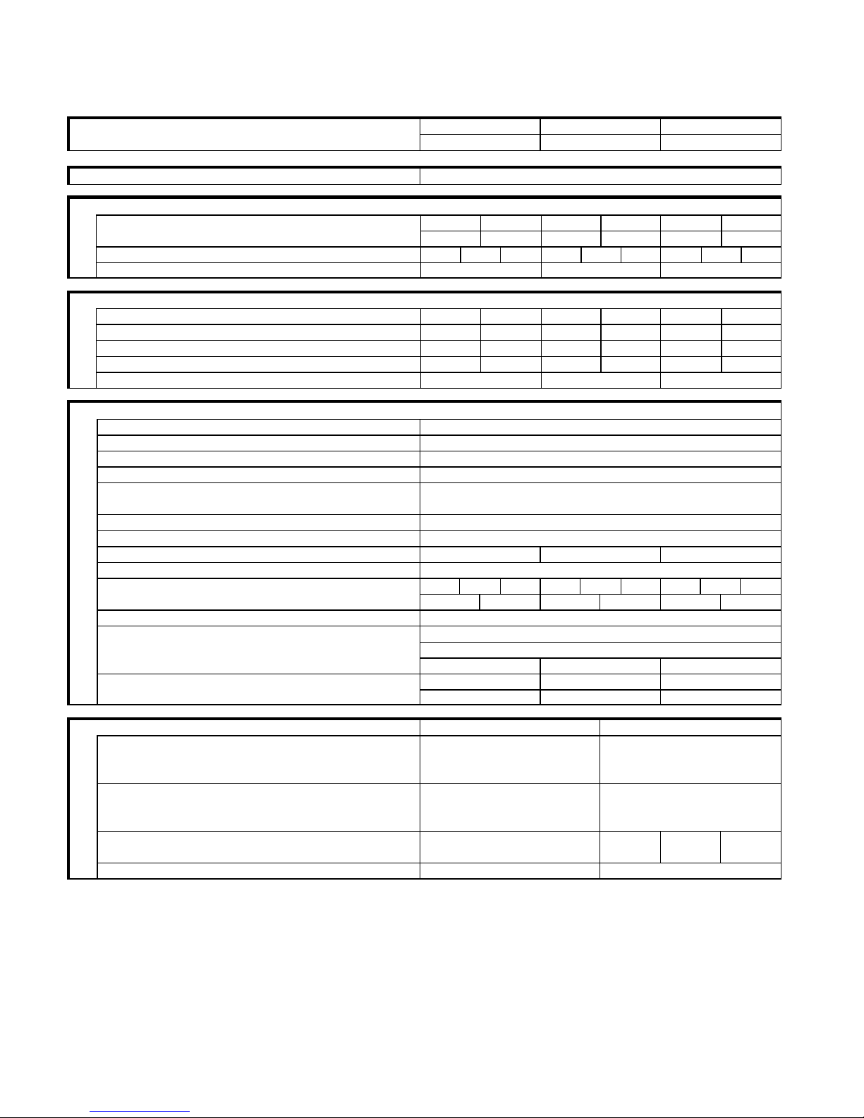
2.SPECIFICATIONS
2-1 Unit Specification
Indoor Unit
MCA120R MCA127R MCA135R
Model Unit
Outdoor Unit
GR120R GR127R GR135R
Voltage Rating 230 V – 50 Hz
Performance
W 2000 2300 2450 2800 3150 3550
Capacity Cooling / Heating
BTU/h
6820 7840 8350 9550 10740 12100
Air Circulation Hi-Me-Low
m3/hr 280 320 420 280 320 420 300 350 450
Moisture Removal Liters/h
0.5 0.8 1.1
Electrical Rating
Running Amperes A 3.2 3.3 4.0 4.0 5.5 5.7
Power Input W 700 720 850 850 1150 1250
Power Factor % 95 95 92 92 90 91
C.O.P W/W 2.86 3.19 2.88 3.29 2.74 2.96
Compressor locked rotor amperes A
20 24 30
Features
Controls / Temperature Control
Microprocessor / I.C. thermostat
Control Units
Wireless remote control unit
Timer
24 hr ON o OFF
Fan Speed Indoor/Outdoor
3-Auto / 1
Horizontal
Manual
Air Flow Direction (indoor)
Vertical
Auto
Air Filter
Washable, Anti-Mold
Compressor
Rotary ( Hermetic )
Refrigerant/Amount charged at shipment g
R22-690 R22-650 R22-690
Refrigerant Control Capillary
Indoor: hi / Me / Lo dB-A 39 33 28 40 35 31 42 38 34
Operation Sound
Outdoor: Cool/Heat dB-A
38 40 37 40 37 40
Refrigerant Tubing Connections Flare
Max Allowable tubing length at shipment mt
7.5
Narrow tube mm (in)
6.35 (1/4”) Refrigerant tube
diameter
Wide tube mm (in)
9.52 (3/8”) 9.52 (3/8”) 12.7 (1/2”)
Lenght mt
10 10 15
Max allowable tubing
Refrigerant
g/m
15 15 15
Dimensional & Weight Indoor Unit Outdoor Unit
Height mm
270 540
Width mm
805 700
Unit dimensions
Depth mm
181 265
Height mm
343 585
Width mm
855 830
Package dimensions
Depth mm
232 360
Net Kg
8 35 36 38
Weight
Shipping Kg
10 38 39 41
Shipping volume m
3
0.07 0.18
DATA SUBJECT TO CHANGE WITHOUT NOTICE .
Remarks:
Rating conditions are:
Cooling : Indoor air temperature 27 °C D.B. / 19 °C W.B.
Outdoor air temperature 35 °C D.B. / 24 °C W.B.
Heating : Indoor air temperature 20 °C D.B.
Outoor air temperature 7 °C D.B. / 6 °C W.B.
Page 6

2-2 Indoor Unit
Model Unit
MCA120R MCA127R MCA135R
Controller PCB
Part No
WSA-LTR
Controls Microprocessor
Control circuit fuse 250 V – 3.15 A
Remote Control Unit
Fan & Fan Motor
Type
Cross-Flow
Q.ty….Dia. and length mm
1- θ 95 / 617
Fan motor model….Q.ty
KFV4Q-11HP-S-----------1
No of poles…rpm (230V,hi)
4-----1160 4-----1160 4------1250
Nominal output W
10
BRN-WHT
561.8
VLT-WHT
197.4
VLT-ORG
63.4
YEL-ORG
155.7
Coil Resistance (Ambient Temp.)
YEL-PNK
115.9
Safety device Type
Internal Fuse
Open °C
145 +/-5
Operating temp.
Close °C
-
µf
0.6 0.6 0.8
Run capacitor
Vac 400 400 400
Flap Motor
Type
Stepping Motor
Model MP24GAI
Rating 12 VDC
Coil resistance (Ambient temp 25°C) ohm
380
Heat Exch.Coil
Coil
Aluminium plate fin/ Copper tube
Rows 2
Fin pitch mm
1.6
Face area m
2
0.13
DATA SUBJECT TO CHANGE WITHOUT NOTICE
Page 7

2-3 Outdoor Unit
Model Unit
GR120R GR127R GR135R
Compressor
Type
Rotary (Hermetic)
Compressor model mm RH130VHAT RH154VHAT RH189VHAF
Nominal output
Compressor oil Diamond MS 56 ….Amount cc
300 300 520
Coil resistance (Ambient temp 25°C)+/- 7% cr
Ω
4.26 3.5 2.64
cs
Ω
5.87 5.55 4.02
Safety device Type
Overload relay
Operating temp Open °C
150 +/-5 150 +/-5 155 +/-5
Close °C
90 +/-10 90 +/-10 90 +/-10
Operating amp(Ambient temp 25°C) Run capacitor
µF
25 25 30
VAC
450 450 450
Grank case heater
Fan & Fan Motor
Type
Propeller
Q.ty….Dia. and length mm
1------θ 370
Fan motor model….Q.ty
K35610-M01723-------1
No of poles…rpm (230V,hi)
6------820
Nominal output W
22
Ω
BRN-WTH 374 +/- 7%
Ω
PNK-BRN 484 +/-7%
Coil Resistance (Ambient Temp.20°C)
-
Safety device Type
Internal protector
Open °C
150 +-10
Operating temp.
Close °C
Auto
µf
1.5
Run capacitor
Vac 400
Heat Exch.Coil
Coil
Aluminium Plate fin / Copper tube
Rows 1
Fin pitch mm
1.6 1.6 1.2
Face area m
2
0.35
External Finish
Acrylic baked-on enamel finish
DATA SUBJECT TO CHANGE WITHOUT NOTICE
Page 8

2-4 Other Component Specifications
¢ Indoor unit
Transformer (TR) TPN41-0001
Primary
230V 50HZ
Secondary
12 V 300mA Rating
Capacity
Ω (at 21°C)
Primary 495
Coil resistance
Secondary 2.86
Thermal cut -off temp.
125°C
Thermistor (Coil sensor) NTC - TERMISTOR
Resistance
KΩ
10 at 25°C
Thermistor (Room sensor)
Resistance
KΩ
¢ Outdoor Unit
4-Way Valve (Solenoid coil) CHV01A(coil) CHV -0101 (valve)
Coil rating
230V-50HZ
Coil resistance
KΩ
1.430 +/- 7%
Thermostat ( Defrost thermo ) NTC - TERMISTOR
Operating Temp °C
–2 / 15 +/-2 ON
Resistance
KΩ
10 at 25°C
Page 9

3.DIMENSIONAL DATA
3-1 Indoor Unit
Page 10

3-2 Outdoor Unit
Page 11
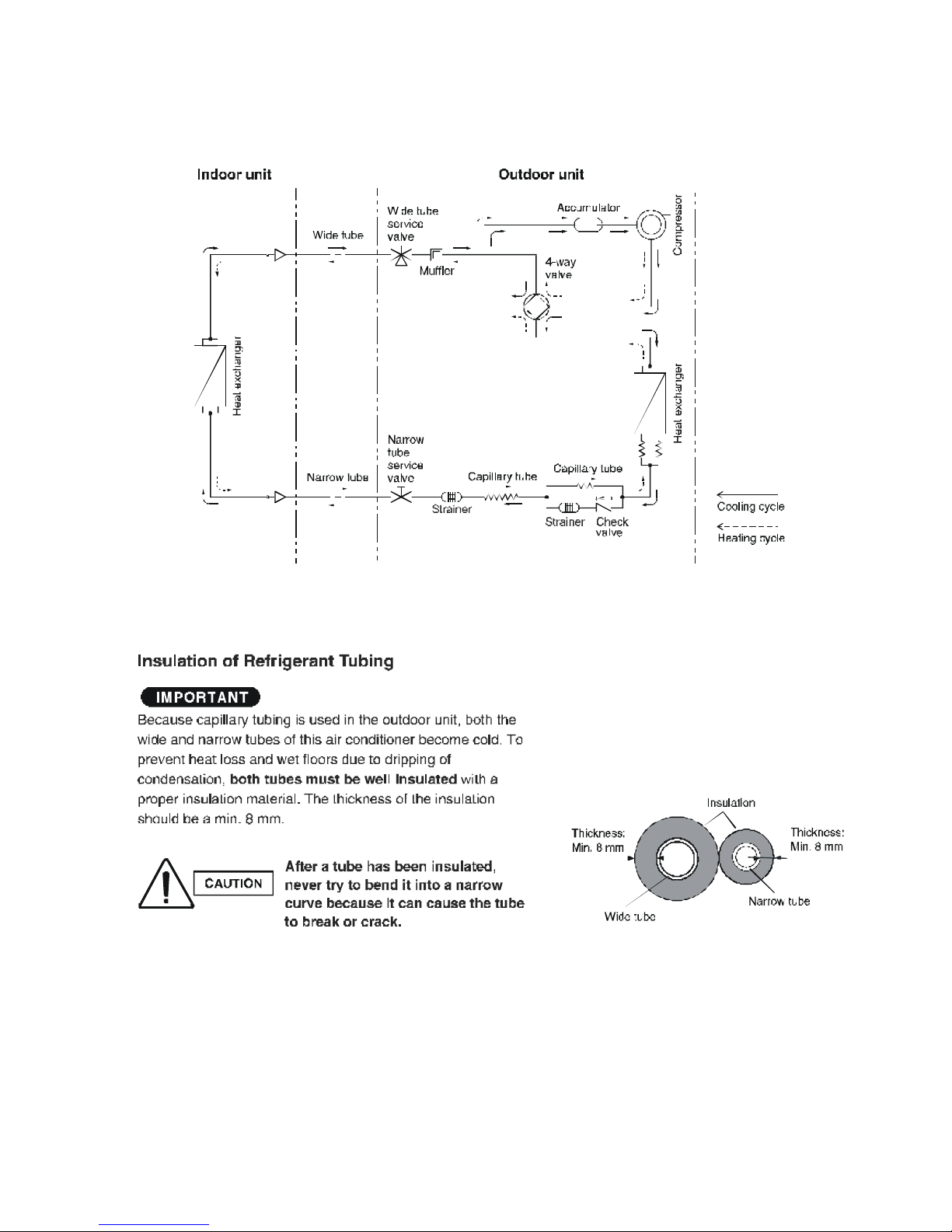
4.REFRIGERANT FLOW DIAGRAM
Page 12

5.PERFORMANCE
5-1 Air Throw Distance Chart
COOLING
Room ir temp : 27°C
Fan Speed : High
Horizontal distance (m)
1
2 3 4 5 6 7 8 9
1
2
3
4
Axis Air Velocity (m/s)
Vertical distance (m)
• Axis air velocity
0°
• Flap angle
30°
HEATING
Room ir temp : 20°C
Fan Speed : High
Horizontal distance (m)
1
2 3 4 5 6 7 8 9
1
2
3
4
Axis Air Velocity (m/s)
Vertical distance (m)
• Axis air velocity
45°
• Flap angle
60°
Page 13

COOLING
Room ir temp : 27°C
Fan Speed : High
Horizontal distance (m)
1
2 3 4 5 6 7 8 9
1
2
3
4
Axis Air Velocity (m/s)
Vertical distance (m)
• Axis air velocity
0°
• Flap angle
30°
HEATING
Room ir temp : 20°C
Fan Speed : High
Horizontal distance (m)
1
2 3 4 5 6 7 8 9
1
2
3
4
Axis Air Velocity (m/s)
Vertical distance (m)
• Axis air velocity
45°
• Flap angle
60°
Page 14

5-2 Cooling Capacity
Indoor Unit MCA127R
Otdoor Unit GR127R
230 V Single Phase 50 HZ
RATING CAPACITY 2.45kW
AIR FLOW RATE 420m³/h
EVAPORATOR CONDENSER
ENT.TEMP. °C OUTDOOR AMBIENT TEMP. °C
W.B. D.B. 25 30 35 40 43
TC 2,32 2,25 2,15 2,01 1,86
CM 0,70 0,75 0,80 0,88 0,96
21 SHC 1,59 1,56 1,51 1,44 1,37
23 SHC 1,80 1,77 1,72 1,65 1,58
15 25 SHC 2,01 1,97 1,92 1,85 1,78
27 SHC 2,22 2,18 2,13 2,01 1,86
29 SHC 2,32 2,25 2,15 2,01 1,86
31 SHC 2,32 2,25 2,15 2,01 1,86
TC 2,51 2,42 2,30 2,16 1,99
CM 0,72 0,77 0,82 0,91 0,98
21 SHC 1,39 1,35 1,30 1,24 1,16
23 SHC 1,60 1,56 1,50 1,44 1,36
17 25 SHC 1,81 1,76 1,71 1,65 1,57
27 SHC 2,02 1,97 1,91 1,85 1,77
29 SHC 2,24 2,17 2,12 2,06 1,98
31 SHC 2,44 2,38 2,30 2,16 1,99
TC 2,66 2,57 #2,45 2,30 2,12
CM 0,75 0,79 0,85 0,93 1,01
21 SHC 1,17 1,13 1,08 1,01 0,94
23 SHC 1,37 1,34 1,28 1,22 1,15
19 25 SHC 1,57 1,54 1,49 1,43 1,35
27 SHC 1,77 1,75 1,69 1,63 1,56
29 SHC 1,97 1,95 1,90 1,84 1,76
31 SHC 2,18 2,16 2,10 2,04 1,97
TC 2,82 2,73 2,60 2,44 2,25
CM 0,77 0,81 0,88 0,96 1,04
23 SHC 1,15 1,11 1,06 1,00 0,92
21 25 SHC 1,35 1,32 1,27 1,20 1,13
27 SHC 1,55 1,52 1,47 1,41 1,33
29 SHC 1,75 1,73 1,68 1,61 1,54
31 SHC 1,96 1,93 1,88 1,82 1,75
TC 3,01 2,89 2,73 2,55 2,38
CM 0,78 0,83 0,90 0,98 1,07
23 25 SHC 1,13 1,08 1,02 0,96 0,89
27 SHC 1,32 1,28 1,23 1,16 1,10
29 SHC 1,52 1,49 1,43 1,37 1,30
31 SHC 1,74 1,70 1,64 1,57 1,51
TC : Total Cooling Capacity KW
SHC : Sensible Heat Capacity KW
CM : Compressor Input KW
Rating Condition (#Mark) are
Outdoor Ambient Temperature 35°C D.B.
Indoor Unit Entering Air Temp 27°C D.B / 19°C W.B.
Page 15

Indoor Unit MCA135R
Otdoor Unit GR135R
230 V Single Phase 50 HZ
RATI NG CAPACITY
3.15 kW
AIR FLOW RATE 450 m³/h
EVAPORATOR CONDENSER
ENT.TEMP. °C OUTDOOR AMBIENT TEMP. °C
W.B. D.B. 25 30 35 40 43
TC 2,99 2,90 2,76 2,59 2,39
CM 0,95 1,01 1,09 1,19 1,30
21 SHC 2,05 2,01 1,94 1,86 1,76
23 SHC 2,32 2,27 2,21 2,12 2,03
15 25 SHC 2,59 2,53 2,47 2,38 2,29
27 SHC 2,86 2,80 2,73 2,59 2,39
29 SHC 2,99 2,90 2,76 2,59 2,39
31 SHC 2,99 2,90 2,76 2,59 2,39
TC 3,23 3,11 2,96 2,78 2,56
CM 0,97 1,04 1,11 1,23 1,33
21 SHC 1,79 1,74 1,67 1,59 1,49
23 SHC 2,06 2,00 1,93 1,85 1,75
17 25 SHC 2,33 2,27 2,20 2,12 2,01
27 SHC 2,60 2,53 2,46 2,38 2,28
29 SHC 2,88 2,79 2,73 2,64 2,54
31 SHC 3,14 3,05 2,96 2,78 2,56
TC 3,42 3,31 #3,15 2,96 2,73
CM 1,02 1,07 1,15 1,26 1,37
21 SHC 1,50 1,45 1,38 1,30 1,21
23 SHC 1,76 1,72 1,65 1,57 1,47
19 25 SHC 2,02 1,98 1,91 1,84 1,73
27 SHC 2,28 2,25 2,18 2,10 2,00
29 SHC 2,53 2,51 2,44 2,36 2,26
31 SHC 2,80 2,77 2,70 2,62 2,53
TC 3,63 3,51 3,34 3,14 2,89
CM 1,04 1,10 1,19 1,30 1,41
23 SHC 1,48 1,43 1,36 1,28 1,18
21 25 SHC 1,73 1,69 1,63 1,55 1,45
27 SHC 2,00 1,96 1,89 1,81 1,71
29 SHC 2,25 2,22 2,16 2,07 1,98
31 SHC 2,52 2,49 2,42 2,34 2,25
TC 3,88 3,71 3,51 3,28 3,05
CM 1,06 1,13 1,21 1,33 1,44
23 25 SHC 1,45 1,39 1,31 1,23 1,15
27 SHC 1,70 1,65 1,58 1,49 1,41
29 SHC 1,96 1,92 1,84 1,76 1,68
31 SHC 2,24 2,18 2,10 2,02 1,94
TC : Total Cooling Capacity KW
SHC : Sensible Heat Capacity KW
CM : Compressor Input KW
Rating Condition (#Mark) are
Outdoor Ambient Temperature 35°C D.B.
Indoor Unit Entering Air Temp 27°C D.B / 19°C W.B.
Page 16

5-3 Heating Capacity
120
110
100
90
80
Heating capacity ratio
(%)
70
60
50
40
30
20
10
0
-8
-5
0
5 7 10
15
Outdoor temperature ( °C D.B.)
NOTE
1)
• Point of Rating condition
Black dot in the chart indicate the following rating condition.
Indoor: 20°C D.B.
Outdoor: 7° C D.B. / 6°C W.B.
2)
Above characteristics indicate instantaneous operation, which does
no take into account defrost operation.
3) Fan speed: High
4)
Because this air conditioner heats a room by drawing in the heat of
the outside air (h
eat pump system),the heating efficiency will fall
when the outdoor temperature is very low. If sufficient heat cannot
be obtained with this air conditioner, user another heating
appliance in conjunction with it.
• Point of Rating Condition
Page 17

6.ELECTRICAL DATA
6-1 Electrical Characteristics
COOLING
Indoor Unit Outdoor Unit
Fan Motor Fan Motor Compressor
Complete Unit
Performance at 230 V – 50 Hz
Rating Conditions Running Amps. A
0.14 0.14 0.14 0.25 0.25 0.25 0.28 3.6 5.1 3.2 4 5.5
Power Input KW
27 27 29 56 56 56 617 767 1065 700 850 1150
Full Load Conditions Running Amps A
0.14 0.14 0.14 0.25 0.25 0.25 3.3 4.1 5.5 3.7 4.5 5.9
Power Input KW
27 27 29 56 56 56 717 927 1165 800 1010 1250
Rating Condition : Indoor air Temperature 27°C D.B. / 19°C W.B.
Outdoor Air T emperature 35 °C D.B.
Full Load condition : Indoor Air Temperature 32 °C D.B. / 23 °C W.B.
Outdoor Air Temperature 4.°C D.B.
HEATING
Indoor Unit Outdoor Unit
Fan Motor Fan Motor Compressor
Complete Unit
Performance at 230 V – 50 Hz
Rating Conditions Running Amps. A
0.14 0.14 0.14 0.25 0.25 0.25 2.9 3.6 5.3 3.3 4 5.7
Power Input KW
27 27 29 56 56 56 717 767 1115 720 850 1200
Full Load Conditions Running Amps A
0.14 0.14 0.14 0.25 0.25 0.25 3.3 4.1 5.5 3.7 4.5 5.9
Power Input KW
27 27 29 56 56 56 717 927 1165 800 1010 1250
Rating Condition : Indoor air Temperature 20°C D.B
Outdoor Air Temperature 7 °C D.B./ 6°C W.B.
Full Load condition : Indoor Air Temperature 27 °C D.B.
Outdoor Air Temperature 24.°C D.B. / 18°C W.B.
GR120R - GR127R - GR135R
GR120R - GR127R - GR135R
Page 18
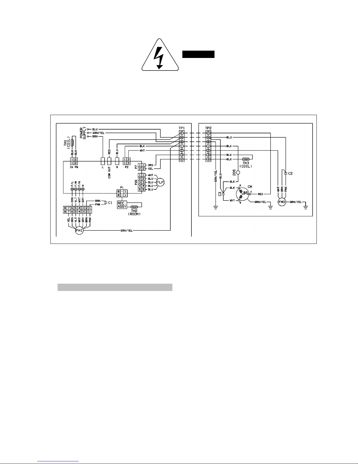
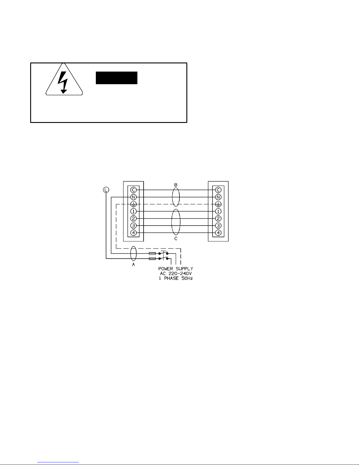
6-2 Electric Wiring Diagrams
WARNING
To avoid electrical shock hazard, be
sure to disconnect power before
checking, servicing and/or cleaning
any electrical parts
Legend
CM
Compressor Motor
C1,C2,C3
Capacitor
FLP
Louvers Motor
FMO
Outdoor Fan Motor
FMI
Indoor Fan Motor
REC ASSY
Remote Control
PCB1
Indoor PC board
TH1,TH2
Thermistor
TP1,TP2
Terminal Plate
Page 19

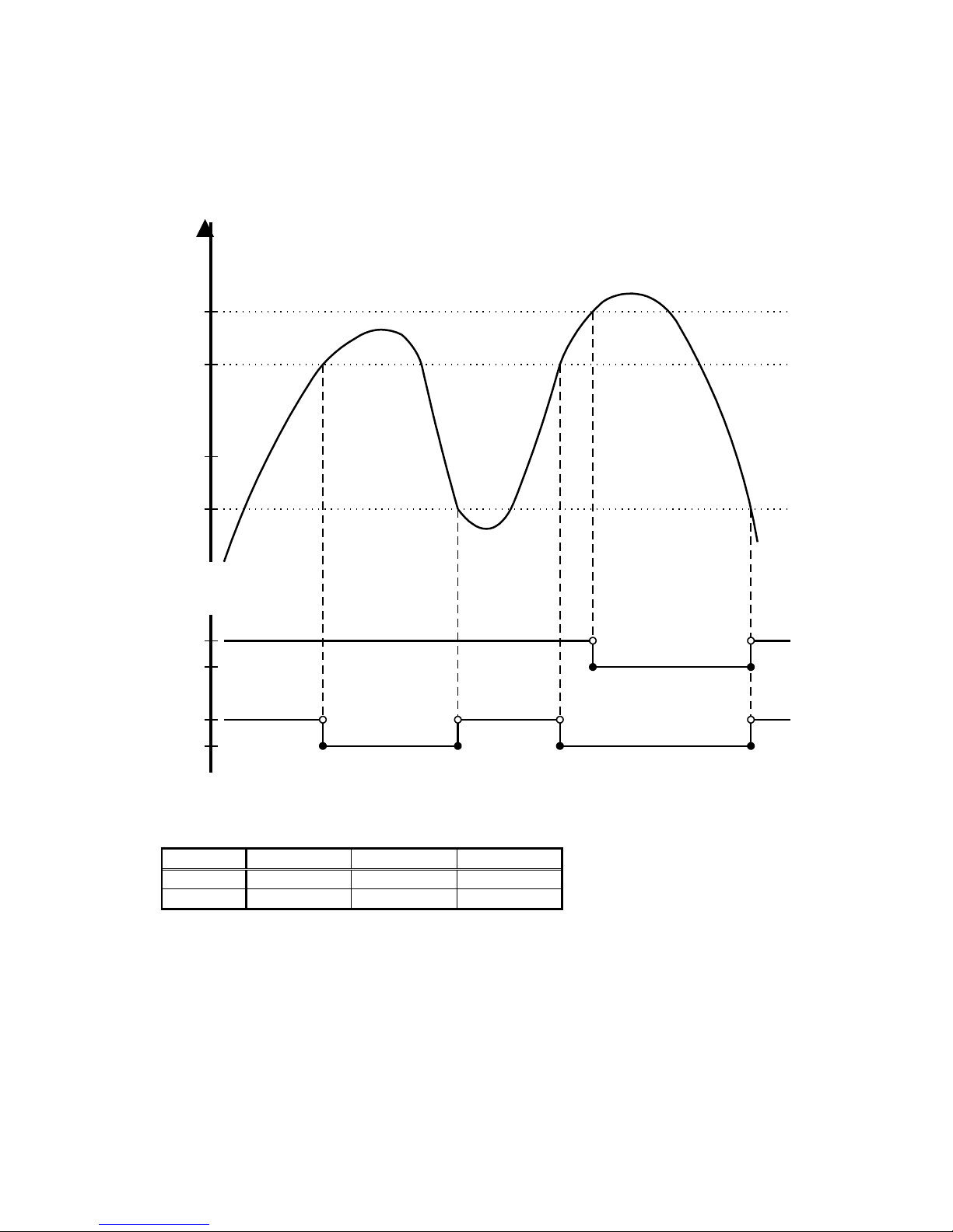
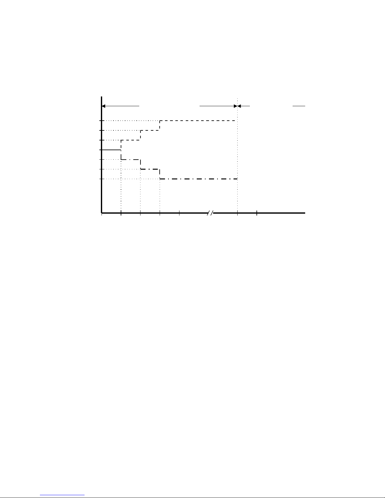
7-1 Cool Mode Operation
(RT - SPT) [oc]
+3
+2
+1
0
-1
ON
OFF
ON
OFF
H
L
M
ON
OFF
COMP
OFAN
IFAN
RV
over 3 min over 5 min
over 30 sec
In Cool Mode, the operation of the Compressor (COMP), Outdoor Fan (OFAN) and Indoor Fan (IFAN)
are determined by the difference between the Room Temperature (RT) and the Set Point Temperature
(SPT) as in the graph above.
Notes:
1. In this graph, the IFAN is operating in the “Auto Fan Speed” setting. If the user has selected the low,
medium or high fan speed, the IFAN will run constantly at that speed only.
2. In addition to the value of (RT-SPT), the operations of the relays are also controlled by protection
delays. For example, (a) the minimum On/Off time of the COMP is 5 min and 3 min respectively, and
(b) the IFAN can change speed only after it has operated at the same speed for 30 sec.
Page 20

7-2 Heat Mode Operation
(RT - SPT) [oc]
+1
0
-1
-2
-3
H
OFF
L
M
ON
OFF
Note 1 Note 2
COMP
IFAN
RV
ON
OFF
30 sec
The Heat Mode operation is similar to the Cool Mode operation. The COMP, OFAN and IFAN are mainly
controlled by the value of (RT – SPT). In the graph above, the IFAN is operating in Auto Fan speed mode.
Therefore, the IFAN speed changes automatically according to the (RT - SPT).
Note 1: The 30s IFAN operation is for purging the heat from the in-coil after COMP has stopped.
Note 2: The IFAN will not be turned on until the in-coil temperature is high enough (as shown in the
graph below) to prevent the unit from supplying cool air.
IFAN Speed
Any
Low
Stop
30 35 40
ICT [oc]
ICT = In-coil Temperature
Any = Hi, Med or Low fan speed which is
selected by the user. In Auto Fan Speed
Mode, the fan speed is selected by the
unit automatically instead.
Low = The indoor fan is forced to operate at low
speed
Page 21

7-3 Auto (Cool/Heat) Mode Operation
(RT - SPT) [oc]
+2
+1
0
-1
-2
ON
OFF
ON
OFF
COMP
& OFAN
RV
Auto Heat Mode Auto Cool Mode Auto Heat Mode
In Auto Mode, the unit switches between the Auto Cooling Mode and Auto Heating Mode
automatically to maintain the room temperature (RT) at the set point temperature (SPT).
Page 22

7-4 Dry Mode Operation
DRY
(RT - SPT) [oc]
+2
+1
0
-1
-2
ON
OFF
LOW
OFF
DRY-ON
DRY-OFF
Time [min]
10
20
30
40 50
COMP
& OFAN
IFAN
5 minutes COMP
ON time
Max 15 minutes Max 15 minutes 6 min
(Note 2)
3.5 min
(Note 1)
In Dry Mode, the unit operates in a mild cool mode to lower the humidity of the room. In order to
maintain a high efficiency in the drying operation without over lowering the room temperature excessively,
the Dry Mode is different from the Cool Mode in two ways.
1. The IFAN is forced to operate at low speed only. And, the IFAN is turned off with the COMP.
2. The unit operates in either the “Dry-on” state or the “Dry-off” state. If RT = SPT, the unit will operate
in “Dry-off” state. The COMP is forced to operate for 6 min after it has stopped working for 15 min.
If RT > SPT, the unit will operate in “Dry-on” state. The COMP is forced off for 3.5 min after it has
been working for 15 min.
Note 1: COMP is forced off in Dry-on state.
Note 2: COMP is forced to operate in Dry-off state.
7-5 Fan Mode Operation
In Fan Mode, the indoor fan is turned on to improve the air circulation in the room. COMP and OFAN
remain OFF all the time.
Note: If the user has selected the Auto Fan Speed setting, the IFAN speed would be selected by the unit
automatically according to the difference between RT and SPT, as in Cool Mode.
Page 23

7-6 Protection Operations in Cool and Dry Modes
1. Indoor Coil Defrost Protection
The in-coil defrost protection can prevent the ice formation at the in-coil when the ambient
temperature is low.
ICT [oc]
+2
ON
OFF
ON
OFF
t1 t2 t3
COMP
OFAN
+1
+5
0
-1
ON
OFF
IFAN
t1 = 5 min minimum for each COMP starting
t2 = OFAN cycling (alternate between ON and OFF every 30 sec) for 20 min maximum
t3 = COMP and OFAN stop for 10 min minimum
Page 24

2. Outdoor Coil High Pressure Protection
The out-coil high pressure protection prevent the build up of high pressure at the out-coil during cooling
operation.
OCT [oc]
ANY
OFF
ANY
ON
ANY
BLINK
ON
COMP
OFAN
IFAN
OPER
LED
52
55
61
64
L
OFAN follow operation of COMP
COMP is forced OFF
OFAN is forced ON (Note 1)
IFAN is forced LOW
Note 1: In some applications, the outdoor fan and the compressor are controlled together by the COMP
relay output from the controller. In this case, it will take more time for the out-coil to cool down
during the high pressure protection, because the outdoor fan will be turned off with the
compressor instead of working as in the graph above.
Page 25

7-7 Protection Operations in Heat Mode
7-7-1 Outdoor Coil Deice Protection
The deice process is controlled by an Ice Detection Algorithm (IDA). The IDA is an unique control
algorithm incorporated to maintain optimal utilization of the heat pump capacity, especially in below-zero
outdoor temperature condition. The out-coil deicing will be activated not only by static temperature
detection as normally done, but also while ice forming is detected on the out-coil.
COMP to ON
DI = 40 (or 10)
DT = 5
Activate DDt setting
Routine
Start counting TLD
DTF = 0
OCT < DOC ?
DTF=1
&
OCT < DDT
(during last 3 minutes)
&
ICT < 40 deg
Deicer activation
(see Notes)
TLD > DI
&
OCT < DST
(during last 3 minutes)
Deicer activation
(see Notes)
LDT > DT + TimeD
LDT < DT-TimeD
or
LDT < DTmin
DI = TLD - DIT DI = TLD + DIT DI = TLD
Yes
Yes
DI < DImin
DI > DImax
DI = DImax
DI = DImin
DT = LDT
1
1
NoNo
Yes
Yes Yes
No No
Yes
Yes
No
No
DDT and DTF information from Deicing
Dynamic Threshold setting routine
No
Page 26

Explanation:
The “Ice Forming Detection” will be done by two algorithms –
1. In Dynamic Temp Detection, the ice formation will be detected by
(i) Compare the OCT with a Deicing Dynamic Temperature Threshold, and
(ii) Detect the drop in ICT which accompany the ice formation.
2. The Static Temp Detection will be done by comparing the OCT with a Deicing Static Temperature
Threshold.
The Deicing Data Record is used to determine the time delay between two deicing cycles. In general, the
time delay will be increased if the last deicing cycle can be completed quickly.
TLD > TST
AND
SCT > SCD
DDT = OCT - TempD
DTF = 1
IFAN/OFAN
speed change
Reset SCT cnt to 0
DTF = 0
DDT and DTF information
to main algorithm
Reset TLD cnt to 0
DTF = 0
Yes
Yes
No
Yes
No
1st COMP start,
OR deice complete
No
Page 27
7-7-2Indoor Coil High Pressure Protection in Heat Mode
The in-coil high pressure protection prevent the build up of high pressure at the in-coil during heating
operation.
Note:
The operation temperatures shown as A and B in the chart differ by models.
MCA120R MCA127R
MCA135R
A 50 54 58
B 42 45 50
ICT [oc]
ANY
OFF
ANY
COMP
OFAN
B
A
64
OFF
COMP is forced OFF
Page 28

7-8 Cold Draft Prevention (Heating)
• This function controls indoor fan speed so a strong draft of cold air will not blow out before the indoor heat
exchange coil have sufficiently warmed up.
• When 10 minutes has elapsed, the fan speed is automatically switched to set speed regardless of indoor heat
exchange coil temperature.
Indoor heat exchange
coil temp. (°C)
Max.10 minutes
Tc
Indoor Fan OFF Set Speed
NOTE
• The operation temperature shown as Tc in the chart differ by models.
MCA120R
MCA135R
Tc 32 32 34
MCA127R
Page 29
7-9-1 Sleep Function
Room temperature is automatically controlled to compensate for body temperature variations while
sleeping. This mode of operation is designed for maximal comfort in both COOL and HEAT modes.
SPT
Time [Hr]
432
Start
Sleep
7 - 12
RT
SPT-1
SPT-2
SPT-3
SPT+2
SPT+1
SPT+3
1
7-12 Hours Sleep operation
Unit is turned to SB
after Sleep
Cool, Dry modes
Heat mode
7-9-2 Daily Timer Function
Unit can be programmed to be ON and OFF automatically at preset time everyday, by using a remote
controller. The resolutions of the ON/OFF timers are 10 min.
7-9-3 IFEEL Function
This feature is provided if the unit is used together with a remote controller with the I-FEEL function.
When this function is selected, the remote controller sends the room temperature measured by its build-in
thermistor to the air con for more accurate temperature control.
7-9-4 Louver Control
The airflow louver can be driven by either a 12V DC stepping motor or an AC motor. The louver can be
set to operate at auto swing mode or fix position mode.
Three additional features are provided if the louver is controlled by a DC stepping motor.
? Different swing positions (range) for Heat Mode and Cool Mode operation
? Last louver position in fix position mode is stored in the EEPROM, and is restored when the unit is
turned on.
? The louver is closed automatically when the unit is switched to standby mode.
Page 30

7-9-5 Manual Unit Control and LED indicators
The push button switch and the LED indicators on the display panel let the user to control the unit
operation without a remote controller. Their operations are provided below.
LED indicators:
STAND BY
INDICATOR
1. Lights up when the Air Conditioner is connected to power and
ready to receive the R/C commands
2. Blinks continuously in case of any thermistor failure.
OPERATION
INDICATOR
1. Lights up in operation mode (Note: OFF in standby mode).
2. Blinks for 0.5 sec., to announce that a R/C infrared signal has
been received and stored.
3. Blinks continuously during
? OCT High Pressure Protection Mode
? Deicing in Heating Mode
TIMER INDICATOR
1. Lights up during Timer and Sleep operation.
2. Active On/Off timer setting will become invalid after a power
failure. When this happens, the unit is forced to restart in STBY
mode, and the Timer Indicator is blinked continuously until (i)
the unit is switched to OPER Mode again, or (ii) any message
from the R/C is received.
Push Button switches:
MODE BUTTON
(Cool, Heat, SB)
Use to cycle the operation mode of the A/C unit among COOL,
HEAT and SB modes, without using the R/C.
Every time this switch is pressed, the next operation mode is
selected, in the order :
SB => Cool Mode => Heat Mode => SB => ...
7-9-6 Recovery from Power Failure
Last unit settings (SPT, operation mode, louver settings, etc) are saved in the EEPROM in the unit. In case
of power failure, these settings are restored automatically.
Page 31
8.TROUBLESHOOTING
8-1 Check before and after troubleshooting
8-2 Check power supply wiring
• Check that power supply wires are connected to terminals L and N on the terminal plate in the indoor unit.
8-3 Check indoor unit wiring
• Check that inter-unit wiring is correctly connected to the outdoor unit from the indoor unit
8-4 Check power supply
• Check that voltage is in specified range (+/- 10% of the rating)
• Check that power is being supplied.
8-5 Check lead wires and connectors in indoor and outdoor units
• Check that coating of lead wires is not damaged
• Check that lead wires and connectors are firmly connected
• Check that wiring is correct.
WARNING
Hazardous voltage can cause ELECTRICAL SCHOCK
or DEATH. Disconnect power or turn off circuit
breaker before you start checking or servicing.
Page 32

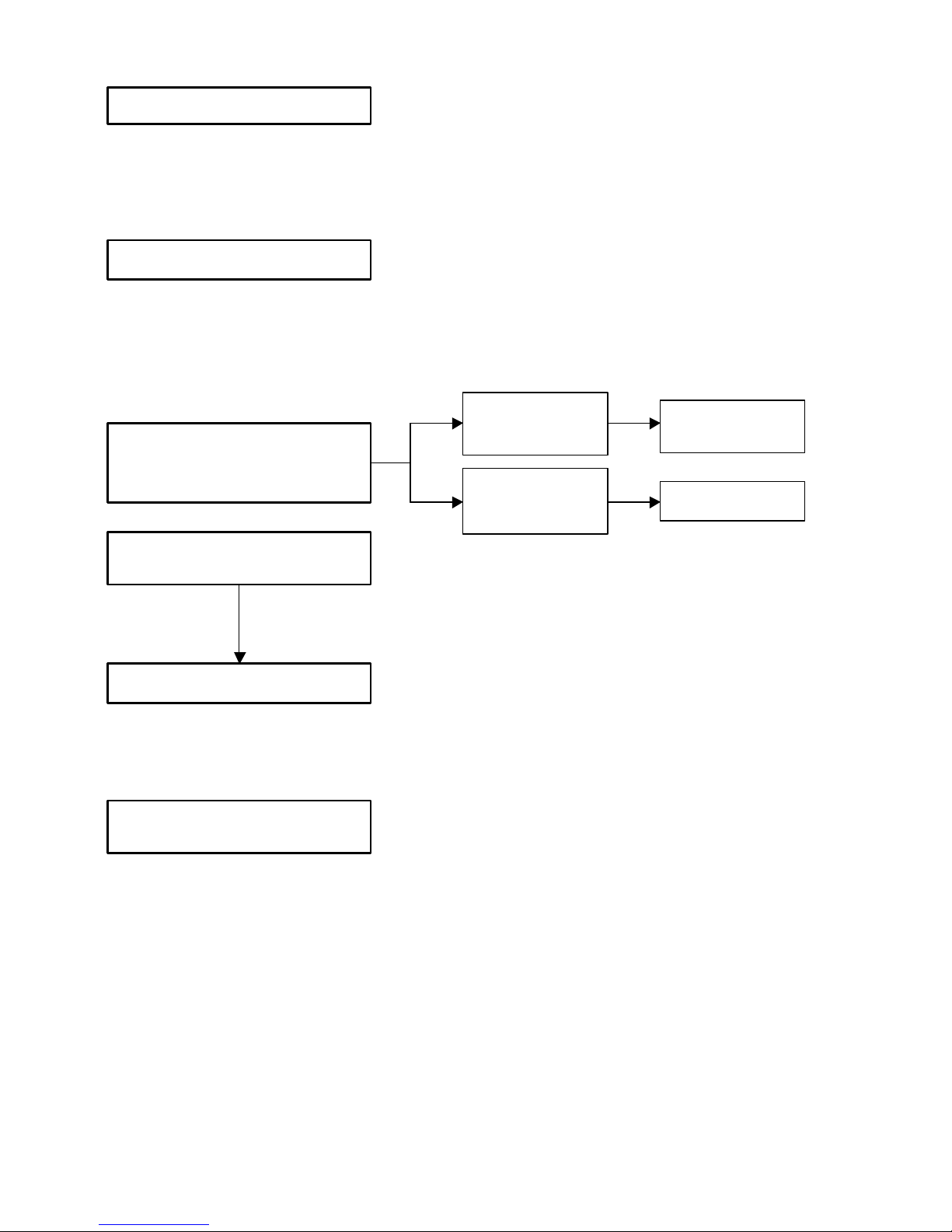
8-6 Air Conditioner does not operate
8-6-1 Circuit breaker trips (or fuse blows).
A. when the circuit breaker is set to ON, it is tripped soon.(resetting is not possible)
• There is possibility of ground fault
• Check insulation resistance
If resistance value is 2MΩor less, insulation is defective ( “NO”)
WARNING
1 Remove inter
-
unit wires
from
terminal platea in outdoor unit
• Mesaure insulation resistance of
outdoor unit.
2 Remove
inter
-
unit wires from
terminal plate un outdoor unit.
Then, pull the power plug out of
the wall outlet.
• Measure insulation resistance of
indoor unit
Insulation of
outdoor unit is
defective
Insulation of
indoor unit is
detective.
NO
NO
• Measure insulation
resiatance of elec
tical parts
in outdoor unit.
• Measure insulation
resiatance of electical parts
in indoor unit.
Page 33

B. Circuit breaker trips in several minutes after turning the air conditioner on.
• There is a possibility of short circuit
8-6-2 Neither indoor nor outdoor unit runs
A. Power is not supplied
B. Check “Push bottom” selector in the indoor unit.
C. Check remote control unit
• Check capacity of circuit
breaker.
Capacity of circuit breaker is
suitable.
• Measure resistance of outdoor
fan motor winding
• Measure resisatnce of
compressormotor winding
Replace with suitable one
(lager capacity)
• Measure resistance of 4-way
valve’s winding
In case of Heating operation:
NO
• Try to run with another remote
control unit.
First remote control unit is detective.
OK
• Check for residue buildup on
transmitter of remote control unit
• Check for residue buildup on
remote control receiver on front
of indoor unit.
Clean transmitter..
Clean Re
ceiver.
• Check power supply.
Power is being supplied to the
indoor unit
Circuit breaker i
tripped
Power failure
Reset breaker
Wait for recovery
or contact power
company
• Push the button switch under the
indoor unit pannel.
The indoor unit
and outdoor unit
doesn’t runs
Indoor PCB Ass’y
is defective
Page 34

D. Check fuse on the indoor PCB Ass’y
E. Check TIMER on the remote control unit
8-6-3 Only outdoor unit does not run
A Check setting temperature
COOL HEAT
• Indoor PCB Ass’y is detective.
• Measure resistance of primari
and secondary winding of
transformer
• Check operation lamp to see if
light is ON
• Check fuse on indoor PCB
Ass’y for continuity
• Replace the fuse
• Measure coil resistance of power
relay in outdoor unit.
• Measure resistance of
compressor motor winding
• Measure resistance of indoor
and outdoor fan motor winding
• Timer i turned On.Check to see
if is displayed on remote control
• Cancel the timer mode push the
buttom CLEAR
OK
OK
OK
Light is OFF
YES
Is room temperature too low?
• Remote control unit is defective
• Try to use another remote
control unit
Try to lower setting temperature by
temperature setting button
Outdoor unit still does
not run
Is room temperature too high?
• Remote control unit is defective
• Try to use another remote
control unit
Try to raise setting temperature by
temperature setting button
Outdoor unit still does
not run
NOOKNO
OK
Page 35
B Check PCB Ass’y in either indoor or outdoor unit
8-6-4 Only indoor unit does not run
8-7 Some part of air conditioner does not operate
8-7-1 Only indoor fan does not run
8-7-2 Only flap motor does not run
• Indoor PCB Ass’y is defective
• Indoor PCB Ass’y is defective
• Check fan rotation
Turn fan gently once or twice by
hand
Check fan casing
foreign matter on
inside
Fan motor burnout
or foreign matter
in bearings
Remove foreign
matter or repair
Repair or replace
• Measure resistance of indoor fan
motor winding
• Check fan motor capacitor
OK
• Measure resistance of flap motor
winding
Fan cannot
be turned
Page 36

8-7-3 Only outdoor fan does not run
8-7-4Only compressor does not run
• Check fan rotation
Turn fan gently once or twice by
hand
Check fan casing
foreign matter on
inside
Fan motor burnout
or foreign matter
in bearings
Remove foreign
matter or repair
Repair or replace
• Measure resistance of outdoor
fan motor winding
• Check fan motor capacitor
OK
Fan cannot
be turned
• Check compressor motor
capacitor (C1)
• Measure resistance of
compressor motor winding
Temperatur
e of compressor
is abnormally high.
Overload Klixon is working
Refigerant gas shortage
Rotor may be locked up
Recover refrigerant
Evacuate the air
conditioner
Charge refrigerant.
Replacement compressor
• Measure power supplì voltage.
The voltage is too low
• Measure winding resistance of
power relay
YES
YES
YESNOYES
NO
Page 37

8-8 Air conditioner operates, but abnormalities are observed
8-8-1 Operation does not switch from HEAT to COOL (or COOL to HEAT).
COOL4 HEAT
HEAT4 COOL
• Remote control unit may be
detective.
• Measure resistance of 4-way
valve’s winding
Reciver in lamp Ass’y may be
detective.
• Check voltage between terminals
No.1 and N, must be 230 VAC
• Indoor PCB Ass’y is defective
Check wiring connection
• Check voltege between terminals
No. 1 and N, must be 0 Volt
OK
No voltage appears
Page 38

8-9 If a sensor is defective
8-9-1 ICT (indoor coil sensor) OCT(outdoor coil sensor) RAT (room ambient temperatur) are defetive.
NOTE Allarm signal (*)
Stan by lampoon the front side of the indoor unit will flash on and off when the thermistor is defective.
At the same time the outdoor unit will stop. Indoor operate only for ventilation.
Temparature sensor
Lead wires
• Stand by lamp on front side of indoor
unit is flashing on and off. (*)
• Thermistor ICT and OCT and RAT are
defective
• Repalce thermistor.
YES
YES
Page 39

9.CHECKING ELECTRICAL COMPONENTS
9-1 Measurement of Insulatipon Resisatnce
The insulation is good condition if the resistance
exceeds 2MΩ
9-1-1Power Supply Wires
Clamp the grounding terminal of the power plug with a
lead clip of the insulation resistance tester and measure
the resistance by placing a probe on either of the two
power terminals.(Fig 1)
Then, also measure resistance between the grounding
and other power terminals (Fig 1)
9-1-2 Indoor Unit
Clamp an aluminium plate fin or copper with the lead clip
of the insulation resistance tester and measure the
resistance by placing a probe on each terminal screw
where power supply lines are connected on the terminal
plate.(Fig 2)
9-1-3 Outdoor Unit
Clamp an aluminium plate fin or copper with the lead clip
of the insulation resistance tester and measure the
resistance by placing a probe on each terminal screw
on the terminal plate.(Fig 2).
Note that ground line terminal should be skipped
9-2 Measurement of Insulation resistance
for electrical Parts
Disconnect the lead wires of the desired electric part
from terminal plate, capacitor, etc. Similarly disconnect
the connector. Then measure the insulation resistance.
(Fig 3 and 4)
NOTE
Refer to Electric Wiring Diagram
If the probe cannot enter the poles because the hole is
too narrow the use a probe with a thinner pin
NOTE
The shape of the power plug may differ from that of the
air conditioner which you are servicing.
Fig. 2
Fig. 3
Fig. 4
Page 40

9-2-1 Measurement continuity of the Fuse
The fuse is situated on Indoor PCB Ass’y (Fig 5)
Disconnect the fuse from PCB Ass’y. Then check if there
is continuity on the fuse(Fig 6)
9-2-2 Measure the Capacity of the Run
Capacitor
Disconnect the lead wires of the desired electric part
from terminal plate. Similarly disconnect the connector.
Then measure the capacity. (Fig 7)
Fig. 5
Fig. 6
Fig. 7
Page 41

S.A.C. - olgiate olona - printed in italy
R.D. 28 Reyrieux BP 131 - 01601 Trévoux CEDEX France
Tél. 04.74.00.92.92 - Fax 04.74.00.42.00
R.C.S. Bourg-en-Bresse B 759 200 728
 Loading...