

Page 1

1
April 2004 10 11 220 - GB - 12
INSTALLATION INSTRUCTIONS
CSCV - L
CONSOLE TYPE SPLIT SYSTEM
R 407 C refrigerant
CSCV 175 L
CSCV 225 L
Page 2

2
• TAV 175 C and 225 C can be connected to the following condensing units
- Axial fan unit : TAV 175 C ➞ GRV 180 L (R 407 C)
TAV 225 C ➞ GRV 220 L (R 407 C)
NOTE
To install the GRV unit:
use these installation instructions.
MARKING
This product marked conforms to the essential requirements of the Directives :
- Low voltage no. 73/23 EEC, modified 93/68 EEC,
- Electromagnetic Compatibility no. 89/336 EEC, modified 92/31 and 93/68 EEC.
1-General ................................................................................................................. 2
2-Presentation.......................................................................................................... 3
3-Positionning of the units........................................................................................ 4
4-Connections .......................................................................................................... 6
5-Indoor unit accessories ......................................................................................... 9
6-Outdoor unit accessories .................................................................................... 11
7-Connecting accessories...................................................................................... 11
8-Starting................................................................................................................ 12
9-Maintenance instructions .................................................................................... 12
10 - Wiring diagrams .................................................................................................. 13
SUMMARY
• The equipment must be installed, started-up and maintained by authorised and qualified personnel, in accordance with local
rules and professional standards.
1.1 - GENERAL SUPPLY CONDITIONS
• Generally speaking, the material is transported at the consignee's risk.
• The consignee must immediately provide the carrier with written reserves if he finds any damage caused during transport.
1.2 - VOLTAGE
• Prior to any operation, check that the voltage specified nameplate agrees with the supply voltage.
1.3 - USE OF EQUIPMENT
• This equipment is intended for the air-conditioning of premises and to provide comfort for the personnel.
1- GENERAL
Page 3
3
80 C 80
55
4-60 x 110
235
A
B
101310189
55
80 80C
600
15
30
110
50
1
2
4
3
5
3
4
2
1
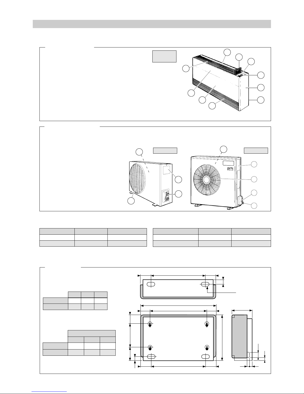
2 - PRESENTATION
INDOOR UNIT - TAV
1 - Outlet grille.
2 - Removable panel.
3 - Front panel.
4 - Inlet grille.
5 - Rear support.
6 - Side.
7 - Control panel.
8 - Control buttons.
9 - Door.
10 - Fixed panel.
2.1 - DESCRIPTION
TAV 175 C
TAV 225 C
OUTDOOR UNIT - GRV
1 - Air inlet (suction).
2 - Fan grille.
3 - Refrigerant connection.
4 - Electrical box access panel.
5 - Tapping point.
GRV 180 L and 220 L : Low temperature version. Use up to -15°C min. / 43°C max. outdoor temperature. extérieure.
Materials:
Painted sheet casing.
Plastic grille.
Copper piping.
Copper/aluminium heat exchanger.
10
9
7
8
6
5
4
3
2
1
Materials:
Plastic coated sheet casing.
Metal grilles.
Polyethylene insulation M1.
Copper/aluminium heat exchanger.
Copper piping.
GR 180 C
2.2 - WEIGHT
Unit
Packed weight
57 kg
76 kg
Net weight
52 kg
67 kg
Unit
TAV 175 C
TAV 225 C
Packed weight
43 kg
49 kg
Net weight
37 kg
42 kg
2.3 - DIMENSIONS
INDOOR UNIT
Under view
Right side
TAV 175 C
TAV 225 C
B
C
790
980
850
1 040
A
950
1 140
Length Height
650
650
Depth
295
295
Packed unit
1 010
1 200
TAV 175 C
TAV 225 C
GR 220 C
NOTE: The refrigerant connections are on the left of the unit, inside the housing.
GRV 180 L
GRV 220 L
Page 4

4
B
A
1
C
B
C
4
8
A
A
A
OUTDOOR UNIT
Length Height
700
900
Depth
400
400
Packed unit
GRV 180 L
GRV 220 L
990
1 000
307
305
20
850
835
620
100
305
325
20
GRV 180 L
GRV 220 L
538
830
146
630
3 - INSTALLATION OF THE UNITS
3.1 - INSTALLATION OF THE INTERNAL UNIT
• It is preferable to handle the air handler without its cabinet, when
installing it.
• If necessary, remove the fan assembly too.
3.1.1 - REMOVING THE CABINET
• Undo the 2 knurled screws (B) and the 2 tinsmith's screws (C).
• Remove the 2 control buttons (8).
• Remove the cabinet by lifting it slightly and pulling it forwards.
NOTE : To make the cabinet easier to handle, the outlet grille (1)
and the inlet grille (4) can be removed beforehand. To do this,
undo the clips (A) by turning them a quarter of a turn using a
screwdriver or a coin.
IMPORTANT : When refitting the grilles, take care to lock the clips
(A) by turning them a quarter of a turn.
3.1.2 - REMOVING THE FAN ASSEMBLY
• Remove the fastening screws.
• Disconnect the loom at connector (D).
• Pull the fan assembly.
3.1.3 - CHOOSING THE LOCATION
AVOID:
• Putting the unit in very damp places. This unit is designed to be installed in sheltered
rooms (IP 20).
• Direct exposure to sunlight or the proximity of heat sources.
• Installing the unit behind curtains or furniture which could prevent air circulation.
• Installing the device near inflammable materials (as it can be equipped with an
electric heater).
MAKE SURE THAT:
• The position is the best one for providing good ventilation in the room.
• That the solidity of the support is adequate for the weight of the unit and does not
cause vibrations.
0.30m
1 m
D
• The position chosen complies with the recommended minimum maintenance spaces (see drawing opposite), and that the
distance and difference in level between the units are as small as possible.
• The piping and the electric connections are easily accessible.
A
Page 5

5
FORWARD
BLOWING
BACKWARD
BLOWING
3
6
7
5
2
4
1
B
B
B
1
9
A
A
7
C
C
7
C
D
D
2
B
9
2
DD
1
A
A
8
9
3.1.4 - MOUNTING
• The system can be placed on the floor or fixed to the wall or ceiling.
• It must be fitted flush against a wall in all cases.
• For wall or ceiling mounting, refer to the Accessories section for the supports which can be used.
3.1.5 - CHOOSING THE BLOWING DIRECTION
A - STANDARD DELIVERY
• Vertical backward blowing.
B - FORWARD BLOWING:
• Turn the grille 180° (see "Removal" below).
3.1.6 - HORIZONTAL BLOWING
• Remove the cabinet (see page 4).
1-Remove the outlet grille (1): undo the two clips (A) by turning them a quarter of a turn (using a screw driver or a coin).
2 - Remove the door (9) by pressing on the side to release the hinge pin (B).
3 - Remove the control panel (7) by taking out the two fastening screws (C).
4 - Remove the removable panel (2) by taking out the four fastening screws (D).
5 - Refit the removable panel (2) on the top and fix it with the four screws (D).
6 - Refit the control panel (7) on the front part and fix it with the two screws (C).
7 - Refit the door (9) by pressing on the side to engage the hinge pin (B) in the hole.
Refit the outlet grille (1) and lock the two clips (A) by turning them a quarter of a turn.
8 - Take out the control panel held by two screws.
9 - Remove the ceiling tray held by 4 screws.
10 - Position the control panel by turning it 90° towards the front.
Fix with the 2 screws.
10
Page 6

6
4 - CONNECTING
1 - Gas refrigerant connection.
2 - Liquid refrigerant connection.
3 - Electrical connection.
4 - Condensate drainage.
5 - Mains supply with isolating and protective
device.
6 - Remote control (accessory).
End piece
Copper pipe
Hose
4.1 -
CONNECTING THE CONDENSATE LINES
4.1.1 - VERTICAL MOUNTING
• Use the 12 mm dia. x 16 mm hose supplied.
• Pass it with refrigerant pipes through one of the covers
and connect it to a pipe of minimum internal diameter
12 mm, respecting a slope in the liquid's flow direction.
4.1.2 - CEILING MOUNTING
• Use the copper pipe and the end piece supplied.
Ceiling mounting
1
23
5
6
GRV
TAV
4
3.2 - INSTALLATION OF OUTDOOR UNIT
• Safety index : IP x 4.
3.2.1 - WALL MOUNTING
• Use the wall support available as an accessory:
- code K 70 U 001 Z.
3.2.2 - FLOOR MOUNTING
• Select the location for the unit on the basis of the following
criteria:
- the unit must be installed outside,
- it is necessary to make sure that the free space around
the unit is provided (see the minimum dimensions on
the drawing opposite),
- installation must be simple and make maintenance
work easy,
- the unit must be fixed on a hard base and must be
protected from risks of flooding,
- the blown air must not be directed towards
surrounding windows,
- vibrations and noise must not be transmitted to a
nearby building.
AVOID:
- Excessive exposure to salty air or sulfuric gas.
- Heat sources and extraction fans.
- Projections of mud (next to a roadway or path, for
example).
- Areas where there is strong wind blowing against the
unit's air exhaust.
GRV 180 L
GRV 220 L
100
20
100
600
50 500
GRV 220 L
Before installation
remove the protective
spacer for
transportation
45°
Page 7

7
4.2 - REFRIGERANT CONNECTIONS
A
B
Outdoor unit
Internal unit
Oil trap
4.2.2 - CONNECTION TO THE INDOOR UNIT
• According to the direction of the outlet chosen, break one of the covers. Protect the point where the pipes go through the sheet
section with the rubber membrane supplied or the rubber profile supplied. For the side outlets, the membrane has to be cut
in two.
Tightening torque
1.5 to 2 kgf-m
3 kgf-m
5 kgf-m
6.5 kgf-m
Dia. of pipes
1/4"
3/8"
1/2"
5/8"
4.2.1 - INSULATION OF PIPES
• Insulate the 2 pipes separately.
• Use polyethylene sheathing at least 8 mm thick.
• Pay particular attention to water entering along the pipes through the wall.
• Connect the gas and liquid pipes on the corresponding Flare connectors.
• Tighten by hand.
• Tighten using torque wrenches (see tightening torque in the table opposite).
• IMPORTANT NOTE: hold the FLARE fitting with a counter-key.
Addition of
refrigerant
above
(m)
Maxaximum
permissible
difference in
level B (m)
Maximum
permissible
length
A (m)
LiquidGas
Dia. of pipes
Quantity of
refrigerant to
be added
(g/m)
Refrigerant
load
in the GRV
(g)
• For connecting lengths greater than 20 m, please contact us.
• If the difference in level is greater than 3 metres, make an oil trap.
NOTE:
The nominal capacity of the units is given for a total length of 8 m.
APPLIANCES FILLED WITH R 407 C
R 407 C
• Fluid R 407 C, as opposed to R22, is not a pure fluid
but a blend composed of:
- 23% R 32 + 25% R 125 + 52% R 134 A.
• The compressors approved for operation with this
fluid are filled beforehand with polyalcohol oil.
Contrary to mineral oil, it is very hygroscopic: it
absorbs the humidity of the ambient air very quickly.
This can modify its lubricant properties and lead in
time to the destruction of the compressor.
MAINTENANCE INSTRUCTIONS
1 - Never add oil to the appliance; the compressor is
filled with polyalcohol oil, a special oil which cannot
tolerate the presence of other oils.
2 - The instruments used for:
- filling,
- pressure measurements,
- emptying under vacuum,
- recovering the fluid,
must be compatible and only used for the R 407 C
fluid.
3 - The weight of the refrigerant contained in the
storage bottle must be checked constantly. Do not
use it from the moment the remaining weight is less
than 10% of the total weight.
4 - In the case of a new charge:
- do not use the charging cylinder,
- use a balance and a dip pipe type R 407 C cylinder,
- charge the weight of R 407 C as per the value
indicated on the unit’s identification plate (for “split
systems”, refer to the installation instructions as the
charge must consider the length of the connecting
lines),
- IMPORTANT: see paragraph 3.
5 - The charge must be undertaken in liquid phase.
6 -
In case of leakage, do not complete the charge:
recover the remaining refrigerant for recycling and
perform a total charge.
Recovery, recycling or the destruction of the fluid must
be done in compliance with the laws in force in the
country concerned.
7 -
If the refrigerant circuit is opened, you must
:
- avoid the entry of air into the circuit as much as
possible,
- replace the filter drier,
- perform the “vacuum operation” at a minimum level
of 0.3 mbar (static).
1/2"
5/8"
CSCV 175 L
CSCV 225 L
1/4"
1/4"
25
25
20
30
7
7
1 660 1-phase
1 680 3-phase
1 620 3-phase
8
8
Page 8

8
Refrigerant valves
Refrigerant valves
GRV 220 L
4.2.4 - USING THE FLARE VALVE
Liquid side
3-way valve
3-waay
valve
Gas side
Indoor
unit
4.3.2 - TABLES OF CURRENT
* The indoor unit
is connected to
230/1/50.
• After completing the connection to the internal and external units, the
connections and internal unit must be bled.
• Proceed as indicated below:
1 - Undo the plugs (1).
2 - Remove the bleed plug (2).
3 - Connect the vacuum pump (3).
4 - We recommend that you fit a shut-off valve (4).
5 - After bleeding, close the shut-off valve (4).
6 - Open the two valves completely until they are right against the seat.
7 - Remove the vacuum pump (3) and the shut-off valve (4).
8 - Tighten the bleed plug (2).
9 - Fully tighten the plugs (1).
10 - Add more charge if necessary (see § 4.2).
Note: Refrigerant and electrical connections can be supplied as accessories. See the "Accessories" section.
Cooling mode
Heating mode
CSCV 175 L
Unit on 400V/3N/50Hz *
Nominal current A
Max. current A
Starting current A
Max. current with heating 2 kW A
3 kW A
4.2
7
21
9.5
14
5.2
8
38
9.5
14
CSCV 225 L
GRV 180 L
Cooling mode
Heating mode
CSCV 175 L
Unit on 230V/1/50Hz
Nominal current A
Max. current A
Starting current A
Max. current with heating 2 kW A
3 kW A
11.2
13.4
52
9.5
14
4.2.3 - CONNECTION TO THE OUTDOOR UNIT
• Connect the gas and liquid pipes on the corresponding Flare
valves.
• Tighten by hand.
• Tighten using torque wrenches (see tightening torque in the table
page 7).
4.3 - ELECTRICAL CONNECTIONS
NOTES :
• Class 1 appliance.
• The electrical connection conduits must be fixed.
• The electrical installation must be carried out in compliance with the rules in force (especially NFC 15-100
CEI 364).
• The cables are not included in the supplies.
MAINS SUPPLY
• The power supply must come from an isolation and electric protection device (not supplied) in accordance with existing
regulations. It is connected to the outdoor unit. See the connection diagram below.
• The acceptable voltage variation is ± 10% during operation.
CAUTION:
In the case of a three-phase power supply, prior to commissioning the unit, make sure that the phase
rotation order is correct.
The phase-sequence controller restricts the unit from operating if the 3 supply phases are
not in order or if a phase is absent.
4.3.1 - CONNECTION CABLES
MAINS POWER CABLE
• on 230V/1/50Hz : 3 G 2.5 mm
2
• on 400V/3N/50Hz : 5 G 1.5 mm2 without electrical heating,
5 G 2.5 mm2 with electrical heating.
C
ONNECTION CABLE BETWEEN THE UNITS
• Use a cable of section equivalent to that of the mains power cable.
NOTE
The sections are given as an
indication only.
They must be checked and
adapted to suit the installation
conditions according to existing
standards.
Page 9

9
4.3.4 - CONNECTION TO THE OUTDOOR UNIT
A - To the GRV 180 L
• Remove the small cover.
• Pass the cables through one
of the covers.
• Connect them to the terminal
board according to the
connection diagrams.
B - To the GRV 220 L
• Remove the side panel.
•Connect them to the
terminal board according to
the connection diagrams.
4.3.5 - CONNECTION DIAGRAMS
L1
1
TAV 175 C
GRV 180 L
230/1//50
5
2
4
230/1/50
LNN
Mains supply 230/1/50
Mains supply 400/3N/50
Connection
cable
5 - INDOOR UNIT ACCESSORIES
adjustment wheels
with threaded rods
Eight 10 mm dia.
holes in the ceiling
60 60
B
D
C
A
A
=
=
50
50
B
13
A
L1
1
5
2
4
L2
L3 NL1
N
TAV 175 C
TAV 225 C
GRV 180 L
GRV 220 L
400/3N//50230/1/50
Connection
cable
5.1 - CEILING SUPPORT
• To make the unit easier to handle, we recommend that you
remove the cabinet as well as the fan assembly (see page 4).
FIXING:
• Drill eight 10 mm dia. holes in the places indicated.
• Insert the 8 S 10 plugs (supplied).
• Fix the 2 bars with the 8 screws (supplied).
• Fix the indoor unit, complying with the minimum and maximum
dimensions. The distance between the bar and the indoor unit
must be a maximum of 20 mm.
IMPORTANT :
Level it, using the adjustment wheels, or with a backward slope
(up to 5 mm).
Type
TAV 175 C
TAV 225 C
A
800
990
B
465
465
C
880
1 070
D
415
415
Accessory code
K 60 U 020 Z
K 60 U 020 Z
Type
TAV 175 C
TAV 225 C
Accessory code
K 60 U 023 Z
K 60 U 024 Z
A
870
1 060
B
850
1 040
5.2 - WALL SUPPORT
• Fix the support to the wall using the screws and plugs supplied.
• Level it using the M6 hex. head screws item A.
5.3 - CROSS DEFLECTION GRILLE
TAV 175 C : Code K 60 N 014 Z TAV 225 C : Code K 60 N 015 Z
• Remove the outlet grille (see page 4).
• The deflection grille is fixed under the outlet grille using plastic clips which are fixed on
the deflection grille and lock onto the outlet grille's pins.
4.3.3 - CONNECTION TO THE INDOOR UNIT
• Pass the cables through one of the covers.
• Connect them to the terminal board according to the connection diagrams.
Page 10

10
5.4 - ELECTRIC HEATING
2 kW : Code K 60 C 842 Z 3 kW : Code K 60 C 843 Z
• See installation instructions supplied with the accessory.
Operating switch
with fan speed selection
Temperature setting knob
Heating / cooling selector switch
K 60 D 076 Z
L
Y1
Q3
Q2
Q1
SR2
SR1
SR
Auto
Y2
TAV
L1
2
1
N
3
4
6
Phase
Neutral
HS
MS
LS
Cooling
Heating
5.5.3 - CONNECTIONS WITH AUTOMATIC REMOTE CONTROL - Code K 60 D 025 Z
On/Off switch
Fan speed selector
Temperature setting knob
K 60 D 025 Z
1
N
2
22
21
20
6
TAV
11
12
L1
2
1
N
3
4
6
Phase
Neutral
HS
MS
LS
Cooling
Heating
Air temperature sensor
(if used)
K 60 D 028 Z or K 60 D 033 Z
5.5 - REMOTE CONTROL
5.5.1 - MONTAGE / INSTALLATION
• See the main characteristics in the Technical Instructions.
• Consult the "Installation instructions" supplied with the control.
• The unit is connected using 0.75mm
2
cable (minimum) (1.5mm2 max.).
The cables used must comply with the insulation requirements for the voltage used (230V).
This information relates above all to the sensor input of the automatic control connected to the 230V supply.
• The temperature adjustment range can be limited by means of the mechanical limit stops located on the control knob.
• Wall mounting:
- Secure the unit at a height of approximately 1.5 m from the floor in a location representative of normal convection
currents, while avoiding:
- wall which are poorly insulated or liable to vibrate,
- the proximity of parasitic heat sources (sunshine, heating appliances, lamps, fireplaces, televisions, etc.),
- currents of air from doors or windows,
- sheltered locations such as shelves or behind curtains,
- near electrical outlets.
- For manual control K 60 D 076 Z, check and modify as required the ventilation selection jumper connection SR
depending on the appliance (see below).
- For the K 60 D 025 Z automatic control, if necessary, adjust the neutral zone using the potentiometer located inside
the control.
• Caution:
If a remote control is used, remove the wire between terminal L1 and switch S1 on the air processor terminal
board.
5.5.2 - CONNECTIONS WITH "RAB 30" MANUAL REMOTE CONTROL - Code K 60 D 076 Z
Position of the SR bridge located inside the controller:
- on SR1 = Permanent ventilation.
- on SR2 (Auto) = Ventilation activated when the thermostat
is in demand.
This position is not accessible with a
heating kit.
Page 11

11
5.5.4 - TEMPERATURE SENSOR ACCESSORIES
• For automatic remote control K 60 D 025 Z
• Temperature sensor K 60 D 028 Z
- CTN 33 kΩ type - IP 67
• Air temperature sensor in box K 60 D 033 Z
- CTN 33 kΩ type - IP 30
• See the specific installation guide.
6 - ACCESSORIES OF THE OUTDOOR UNIT
Wall
support
A
100100
31
2
GRV 180 L
GRV 220 L
A (mm)
538
620
50
mini
6.1 - WALL MOUNTING - Code K 70 U 001 Z
1-After making sure that the fixing system used is suitable for the wall, fix the 2 vertical brackets to the wall.
Make sure that measurement A is correct.
2-Fit the 2 arms using the M8 screws provided.
3 - Fit the unit on the supports using the M8 screws supplied.
7 - CONNECTING ACCESSORIES
Length Code
K 70 A 02 BT
K 70 A 04 BT
K 70 A 08 BT
K 70 A 12 BT
K 70 A 15 BT
K 70 A 20 BT
Unit
CSCV 175 L
7.1 - REFRIGERANT CONNECTIONS
• These connections include 2 insulated refrigeration lines.
2 m
4 m
8 m
12 m
15 m
20 m
Length Code
K 70 A 04 CT
K 70 A 08 CT
K 70 A 12 CT
K 70 A 15 CT
K 70 A 20 CT
Unit
CSCV 225 L
4 m
8 m
12 m
15 m
20 m
7.2 - COMPLETE CONNECTION ASSEMBLIES
• These include: - the refrigeration lines,
- the electric cables,
-a condensate tube.
Length Code
Unit
CSCV 175 L
2 m
4 m
8 m
12 m
15 m
20 m
Length Code
Unit
CSCV 225 L
4 m
8 m
12 m
15 m
20 m
K 70 A 02 BT
+ K 70 A 02 XT
K 70 A 04 BT
+ K 70 A 04 XT
K 70 A 08 BT
+ K 70 A 08 XT
K 70 A 12 BT
+ K 70 A 12 XT
K 70 A 15 BT
+ K 70 A 15 XT
K 70 A 20 BT
+ K 70 A 20 XT
K 70 A 04 CT
+ K 70 A 04 XT
K 70 A 08 CT
+ K 70 A 08 XT
K 70 A 12 CT
+ K 70 A 12 XT
K 70 A 15 CT
+ K 70 A 15 XT
K 70 A 20 CT
+ K 70 A 20 XT
Page 12

12
8.1 - PRELIMINARY CHECKS
• Make sure:
- that the refrigerant fittings are correctly tightened and that the two shut-off valves are open.
- that there are no leaks.
- that the air handler and the condenser unit are well fixed.
- that the power cables are well fixed to their connection terminals. Loose terminals can cause heat build-up on the terminal
board.
- that the electric cables are properly insulated from any pieces of sheet or metal parts which could damage them.
- that the unit is connected to earth.
- that no tools or any other objects have been left in the units.
- that the filter is correctly fitted.
- that the condensate discharge outlet is correctly connected.
8.2 - SWITCH ON THE UNIT
• Using the isolation and protection device.
8.3 - START THE UNIT
• Using the indoor unit's control panel.
- Turn the switch to the required position.
- Set the temperature using the thermostat (see "User manual").
8.4 - EXTERNAL UNIT FAN
• The GRV 180 L and 220 L units are an all-season adjustable fan speed system standard equipment.
Fan motor speed varies according to the pressure of condensation and the outside temperature.
8 - STARTING
9 - MAINTENANCE INSTRUCTIONS
IMPORTANT
Before doing any work on the installation, make sure it is switched off and put out of bounds.
All operations must be carried out by personnel that are approved and qualified for this type of equipment.
• Air filter: Clean every 15 days. See "Operating Manual".
• External unit air exchanger: Cleaning recommended once a year.
• Electric connections: Once a year, check that the electric wires are well fastened to their terminals.
• Electric box: Dusting is recommended once a year.
IMPORTANT
Before doing any work on the installation, make sure it is switched off and put out of bounds.
All operations must be carried out by personnel that are approved and qualified for this type of equipment.
Page 13

13
N
6
JV
BW
B
R
L1
RW
NW LW
B
1234567
M1
RW
NW LW
B
1234567
W
M1
M1
N
L1L1
BN
S1
θ
SA
NL
NL
B1
NG
SF
4
3
SB SBSB SE
0
2
S6
S2 S4S3 S5
6123
G
RW
4
5
θ
B3
G
4
3
GW
C1
N
B
B
NWLWR
RWNWLW
JV
L1
N
N
B
R
6
W
C3
TAV 175 C - TAV 225 C - 230/1/50 10 05 443 - 02
Electric heating
connection
K 60 C 842 Z 2 kW
Electric heating
as accessory
K 60 C 843 Z 3 kW
Outdoor
unit control
TAV 225 CTAV 175 C
Speed connection
S
1
2
3
4
5
6
7
8
S1
0
1
1
1
1
1
1
1
S2
0
1
0
0
1
0
1
0
S3
0
0
1
0
0
1
0
1
S4
0
0
0
1
0
0
0
0
S5
0
0
0
0
0
0
1
1
S6
0
1
1
1
0
0
0
0
B1 Room thermostat
B3 Anti-frost thermostat
C1 M1 capacitor
C3 Filtration capacitor
M1 Fan
S Switch
B Blue
BW Blue/White
G Grey
GW Grey/White
JV Yellow/
Green
LW Purple/White
N Black
NG Black/Grey
NL Black/Purple
NW Black/White
R Red
RW Red/White
W White
10 - WIRING DIAGRAMS
GRV 180 L - 230/1/50
L
N
1
2
3
4
TP
FM
P
M
W
CM
W
N
R
JV
JV
JV
W
N
N
N
B
B
J
R
G
M
B
J
W
R
R
O
JV
S
R
C
CCH
N
W
1
0
KM2
A1
HPS
T
284
6
3
2
1
LOAD
N2
N1
LINE
3
C
H
L
2
1
C1 C2
Power supply
230/1/50
t7
B Blue
G Grey
J Yellow
JV Yellow/Green
L Purple
M Brown
N Black
O Orange
P Pink
R Red
W White
A1 Speed controller
C1 Fan capacitor
C2 Capacitor compressor
CCH Crankcase resistor
CM Compressor
FM Fan
HPS High pressure sensor
KM2 Compressor contactor
T Thermostat
TP Terminal board
Page 14

14
GRV 220 L - 400/3N/50
B Blue
G Grey
J Yellow
JV Yellow/Green
M Brown
N Black
O Orange
A1 Speed controller
C1 Fan capacitor
CCH Crankcase resistor
CM Compressor
FM Fan
HPS High pressure sensor
KM2 Compressor contactor
NPR Phase sequence controller
OLR Protection relay
T Thermostat
TP Terminal board
P Pink
R Red
W White
GRV 180 L - 400/3N/50
Power supply
400/3N/50
Indoor unit
L1
L2
L3
TP
N
1
2
4
A1
NPR
1
2
3
R
U
U/2
8/95
7/96
W/6
VW
14
R
R
T
S
a/A1
b/A2
ST
13
S
T
LOAD
N1
N2
LINE
1
2
3
HPS
CCH
T
C
LH
R
G
G
B
B
G
JV
G
R
R
R
R
W
W
JV
M
G
B
N
J
R
B
G
M
B
B
J
CM
W
B
N
G
W
P
M
R
R
J
JV
KM2
F2
JV
FM
C1
B
C
A
A1 Speed controller
C1 Fan capacitor
CCH Crankcase resistor
CM Compressor
F2 Compressor internal protection
FM Fan
HPS High pressure sensor
KM2 Compressor contactor
NPR Phase sequence controller
T Thermostat
TP Terminal board
B Blue
G Grey
J Yellow
JV Yellow/Green
L Purple
M Brown
N Black
O Orange
P Pink
R Red
W White
Power supply 400/3N/50
Indoor unit
N
4
2
1
L3
L2
L1
U
R
B
A
KM2
A
B
C
R
S
T
SVTW13
14
WU
8
7
CM
R
S
T
1
2
3
LOAD
LINE
N2
N1
3
2
1
CCH
FM
L
H
C
NPR
OLR
TP
C1
T
A1 HPS
JV
G
R
M
G
G
G
G
B
R
R
R
W
W
JV
R
B
N
R
G
O
G
R
B
N
P
M
G
W
J
P
M
G
W
J
JV
JV
R
W
B
N
J
G
Page 15

15
R.D. 28 Reyrieux BP 131 01601 Trévoux CEDEX France
Tel. 33 4 74 00 92 92 - Fax 33 4 74 00 42 00
R.C.S. Bourg-en-Bresse B 759 200 728
Due to our policy of continuous development, our products are liable to modification without notice.
 Loading...