

Page 1
1
10 11 341 - GB - 05
February 2003
CP(V) 188 - 268
SLIMLINE DUCTABLE SPLIT AIR CONDITIONER
CP 188 R
CP 268 R
CPV 188 L
CPV 268 X
INSTALLATION INSTRUCTIONS
Page 2

2
MARKING
This product marked conforms to the essential requirements of the Directives:
- Low voltage no. 73/23 EEC, modified 93/68 EEC,
- Electromagnetic Compatibility no. 89/336 EEC, modified 92/31 and 93/68 EEC.
SUMMARY
1-General.......................................................................................... 2
2-Presentation .................................................................................. 3
3-Positionning of the units ................................................................ 5
4-Connections................................................................................... 6
5-Indoor unit accessories ............................................................... 12
6-Outdoor unit accessories............................................................. 15
7-Connecting accessories .............................................................. 16
8-Control ......................................................................................... 16
9-Starting up ................................................................................... 20
10 - Maintenance instructions............................................................. 21
11 - Pressure curves........................................................................... 22
12 - Electrical connection diagrams.................................................... 24
13 - Wiring diagrams........................................................................... 28
To install the GR unit:
use these installation instructions.
NOTE
1 - GENERAL
• The equipment must be installed, started-up and maintained by authorised and qualified personnel, in accordance with local
rules and professional standards.
1.1 - GENERAL SUPPLY CONDITIONS
• Generally speaking, the material is transported at the consignee's risk.
• The consignee must immediately provide the carrier with written reserves if he finds any damage caused during transport.
1.2 - VOLTAGE
• Before carrying out any operation, check that the voltage indicated on the unit corresponds to the mains voltage.
1.3 - USE OF EQUIPMENT
• This equipment is intended for the air-conditioning of premises and to provide comfort for the personnel.
1.4 - REGULATIONS
• Check that the installation conforms to the relevant specific regulations, for example, the regulation covering areas designed
to receive people.
• PA units can be connected to the following types of condensing unit:
- Axial fan units (cooling only) : PA 188 C ➞ GRV 180 L (R 407 C)
PA 268 X ➞ GRV 265 X (R 407 C)
- Axial fan units (heat pump) : PA 188 R ➞ GR 188 R (R 22)
PA 268 R ➞ GR 268 R (R 22)
Page 3

3
269
25
202
24
445
305
233
934
870=
528
360
79
=40
909= =
Ø17
75
170
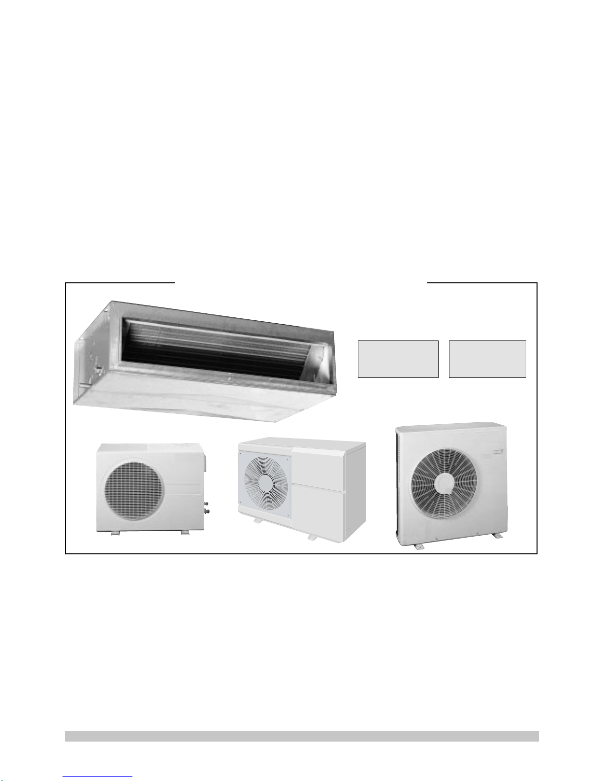
INDOOR UNIT - PA
4
2
1
3
PA 188 C
PA 268 X
2 - PRESENTATION
2.1 - DESCRIPTION
NOTE: - The PA-C and X models (cooling only) are supplied without regulation.
- The PA-R models (heat pump) come with specific electronic regulation with wired remote control.
OUTDOOR UNIT - GR(V)
2.2 - DIMENSIONS AND WEIGHTS OF THE UNITS
INDOOR UNIT - PA
Weight: 33 kg
PA 188 R
PA 268 R
6
5
3
1
8
4
7
2
GRV 180 L:
Low temperature version.
Use up to -15°C min. / 43°C max.
outdoor temperature.
GR 268 R
PA 188 C
PA 268 X
PA 188 R
PA 268 R
7
5
9
8
1 - Blowing
2 - Suction
3 - Electrical box
4 - Ventilation
Materials:
Sheet metal casing.
Polyethylene insulation M1.
Copper/aluminium evaporator.
Copper piping.
1 - Plate-fin exchanger.
2 - Compressor.
3 - Electrical box.
4 - Fan.
5 - Refrigerant connections.
6 - Holes for pipes and electric cables.
7 - Tapping points.
8 - Fan grille.
9 - Electrical box access panel.
Materials:
Painted sheet casing.
Plastic grille.
Copper/aluminium evaporator.
Copper piping.
Flare fitting,
gas 1/2" (PA 188)
5/8" (PA 268)
Flare fitting,
liquid 1/4" (PA 188)
3/8" (PA 268)
4 mounting
holes, 4 x 20
Condensate
tube
Electrical
box
Rear view
8
9
5
GRV 180 L
GR 188 R
GRV 265 X
Page 4

4
D
E
C
A
B
B
A
C
D
E
OUTDOOR UNIT - GR(V)
830
630
538 146
305
307
20
1060
697
543 258.5258.5 400
20
370
850
835
620
100
305
325
20
GR 268 R
A mm
B mm
C mm
D mm
E mm
Weight kg
934
54
258
886
213
2.5
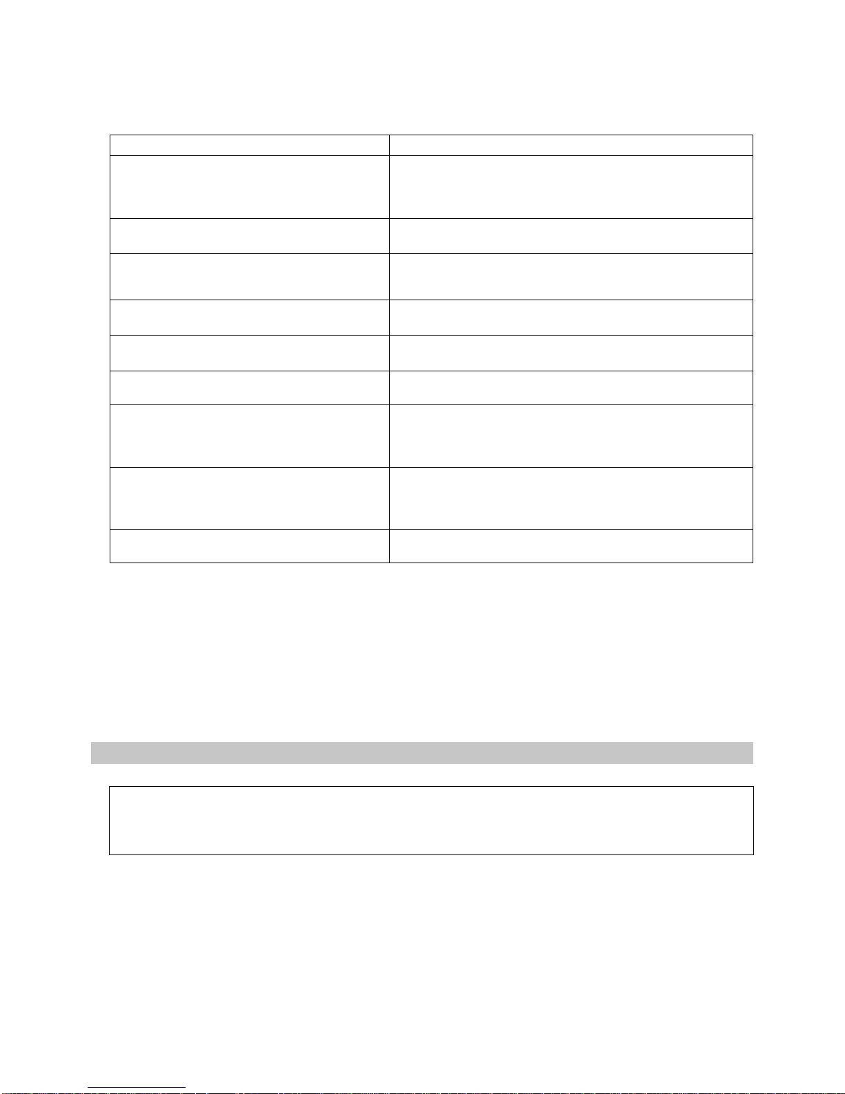
2.3 - DIMENSIONS AND WEIGHTS OF THE ACCESSORIES OF THE PA
PA 188 C / R
PA 268 X / R
Accessories
AIR
A mm
B mm
C mm
D mm
E mm
Weight kg
Plenum with 160 mm dia. spiggots for
round ducts.
There is a plenum to install on the unit’s
delivery side (directly or on the electric
heater kit) and a plenum to install on the
airflow return side.
PLENUM WITH ROUND SPIGGOTS
A mm
B mm
C mm
D mm
Weight kg
A mm
B mm
C mm
Weight kg
874
174
80
3.5
874
210
36
75
2.5
A
B
C
D
A
B
C
Number of spiggots: PA 188 = 3, PA 268 = 4
1 070
215
310
870
170
12
Airflow
return side
887
255
35
75
2.5
The filter kit can be mounted on the back of
the unit or on the front panel.
This kit can also be used as a simple sleeve
by removing the filter.
FILTER WITH SPIGGOT
The electric heater is fitted onto the unit's
exhaust.
ELECTRIC HEATING
This grille can only be mounted on the
unit’s delivery side (directly or on the
electric heater kit).
DOUBLE DEFLECTOR GRILLE
Delivery
side
GRV 265 X
GRV 180 L
GR 188 R
Weight (kg)
52
54
65
70
GRV 180 L
GR 188 R
GRV265 X
GR 268 R
Page 5

5
150
500 200
A
21
21
10
3 - INSTALLATION OF THE UNITS
3.1 - INSTALLATION OF THE INDOOR UNIT
• The appliance can be installed vertically or horizontally.
3.1.1 - RECOMMENDATIONS
• Safety index: IP 20.
AVOID:
• Putting the unit in very damp places.
• Direct exposure to sunlight or the proximity of heat sources.
• Installing the unit above electric appliances.
MAKE SURE THAT:
• The position is the best one for providing good ventilation in the
room (do not place the blower and intake orifices too near each
other).
• That the solidity of the support is adequate for the weight of the unit
and does not cause vibrations.
• The position chosen complies with the recommended minimum
maintenance spaces (see drawing opposite), and that the distance
and difference in level between the units are as small as possible.
• The piping and the electric connections are easily accessible.
Dimension A:
If the filter kit is installed on the unit, dimension
A must be at least 250 mm (to facilitate filter
removal).
3.1.2 - POSSIBLE INSTALLATION CONFIGURATIONS
1 - Horizontal installation 2 - Vertical installation
Note:
The unit is supplied in configuration 1 as standard.
3.1.3 - CONFIGURATION MODIFICATION
• For suction at the front of the unit, remove the panel's 4 retaining
screws, turn the panel and secure it to the bottom of the unit.
3.1.4 - UNIT INSTALLATION
• Once the configuration has been selected, install any accessories
on the unit (see chapter entitled "Indoor unit accessories").
• Secure the unit to the wall or ceiling using the 4 mounting holes
provided at the back.
Secure the unit with either screws or M8 threaded lugs.
• In horizontal assembly, the appliance must be positioned as shown
in the drawing opposite to ensure that condensates flow toward the
outlet and that the appliance operates correctly.
Page 6
6
• Safety index: IP x 4.
3.2.1 - WALL MOUNTING
• Use the wall support (supplied as an accessory):
- reference K 70 U 001 Z for GRV 180 L,
GR 188 R and GR 268 R.
-reference K 60 U 035 Z for GRV 265 X.
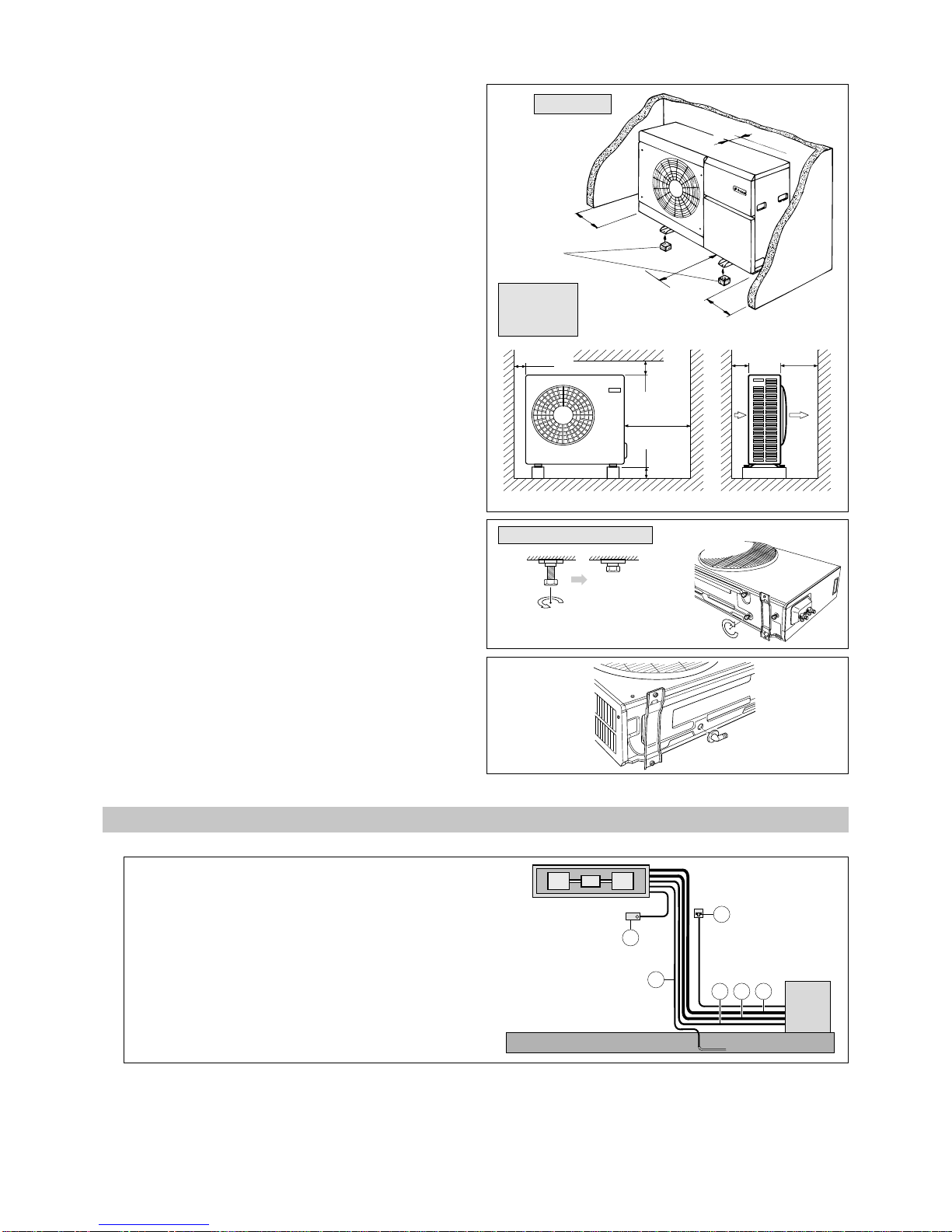
3.2.2 - FLOOR MOUNTING
• Select the location for the unit on the basis of the following
criteria:
- the unit must be installed outside,
- it is necessary to make sure that the free space around
the unit is provided (see the minimum dimensions on
the drawing opposite),
- installation must be simple and make maintenance
work easy,
- the unit must be fixed on a hard base and must be
protected from risks of flooding. We recommend that
the GR 188 R and the GR 268 R be raised
approximately 100 mm off the ground to facilitate the
installation of condensate drainage tubing, as required,
-
use the anti-vibration mountings supplied (GRV 265 X),
making sure that they are not compressed too much
when the fastening screws are tightened,
- ensure that the exhaust is not directed toward
surrounding windows,
- ensure that noise and vibrations are not transmitted to
the building.
AVOID:
- Excessive exposure to salty air or sulfuric gas.
- Heat sources and extraction fans.
- Projections of mud (next to a roadway or path, for
example).
- Areas where there is strong wind blowing against the
unit's air exhaust.
DRAINAGE OF CONDENSATES
- For the GR 188 R and the GR 268 R, use the
condensate drainage connection accessory as
required.
(100)
20
100
50
(500)
50
(600)
250
400
0.15 m
0.50 m
1 m
0.17
Values in parentheses concern model GR 268 R
4 - CONNECTIONS
4
5
3
2
1
6
PA
GR(V)
3.2 - INSTALLATION OF THE OUTDOOR UNIT
Anti-vibration
mounting
Before installation,
screw in the bolts as shows.
1-Gas refrigerant connection.
2 - Liquid refrigerant connection.
3 - Electrical connection.
4 - Condensate drainage.
5 - Mains supply with isolating and protective device.
6 - Remote control:
- accessory for cooling only models,
- standard option for heat pump models.
4.1 - CONDENSATE CONNECTION
• The unit is fitted with a drainage tube on each side (O.D. 17 mm).
• Connect a drainage tube to the selected end fitting while respecting a slope in the liquid's flow direction.
• Be sure that the plastic cap is installed on the unused end fitting.
• All connections are made on the left-hand side of the unit (see page 3).
GRV 265 X
GRV 180 L
GR 188 R
GR 268 R
GRV 180 L - GR 188 R
Page 7

7
90
45
• First of all remove the top front panel by undoing the 2 clips
A a quarter of a turn.
Pull the front panel towards you and lift it.
• Then remove the bottom front panel by undoing the 2 clips
B a quarter of a turn.
Pull the front panel towards you and lift it.
Gas valve
Liquid valve
Hole for pipes and cables
HP tapping point
Hole for electric
cables
LP tapping point
Electrical equipment cabinet
• The pipes and cables are inserted through
the right-hand side of the unit.
Open the cap and use the rubber profiled
section supplied as protection.
Note:
To make it easier to install the pipes, the
stiffener can be removed. Make sure that it is
then re-fitted for good panel rigidity.
4.2 - PREPARING THE OUTDOOR UNIT - GRV 265 X
(to gain access to the refrigerant valves and electrical box)
Stiffener
4.3 - REFRIGERANT CONNECTION
* For lengths greater than 20 m, please consult us.
• If the difference in level is greater than 3 metres, do an oil trap.
NOTE:
The nominal capacity is given for a total length of 8 m.
Indoor unit
A
B
Oil trap
Outdoor unit
APPLIANCES FILLED WITH R 407 C
R 407 C
• Fluid R 407 C, as opposed to R22, is not a pure fluid but a blend
composed of:
- 23% R 32 + 25% R 125 + 52% R 134 A.
• The compressors approved for operation with this fluid are filled
beforehand with polyalcohol oil.
Contrary to mineral oil, it is very hygroscopic: it absorbs the
humidity of the ambient air very quickly. This can modify its
lubricant properties and lead in time to the destruction of the
compressor.
MAINTENANCE INSTRUCTIONS
1 - Never add oil to the appliance; the compressor is filled with
polyalcohol oil, a special oil which cannot tolerate the presence
of other oils.
2 - The instruments used for:
- filling,
- pressure measurements,
- emptying under vacuum,
- recovering the fluid,
must be compatible and only used for the R 407 C fluid.
3 - The weight of the refrigerant contained in the storage bottle must
be checked constantly. Do not use it from the moment the
remaining weight is less than 10% of the total weight.
4 - In the case of a new charge:
- do not use the charging cylinder,
- use a balance and a dip pipe type R 407 C cylinder,
- charge the weight of R 407 C as per the value indicated on the
unit’s identification plate (for "split systems", refer to the
installation instructions as the charge must consider the
length of the connecting lines),
- IMPORTANT: see paragraph 3.
5 - The charge must be undertaken in liquid phase.
6 - In case of leakage, do not complete the charge: recover the
remaining refrigerant for recycling and perform a total charge.
Recovery, recycling or the destruction of the fluid must be done
in compliance with the laws in force in the country concerned.
7 - If the refrigerant circuit is opened, you must:
- avoid the entry of air into the circuit as much as possible,
- replace the filter drier,
- perform the "vacuum operation" at a minimum level of 0.3
mbar (static).
Model
Dia.of pipes
Liquid
1/2"
5/8"
1/2"
5/8"
1/4"
3/8"
1/4"
3/8"
7
10
7
10
Gas
> 2 m 25 g/extra m
> 2 m 35 g/extra m
> 0 m 35 g/extra m
> 2 m 55 g/extra m
20
20
20
20
CPV 188 L
CPV 268 X
CP 188 R
CP 268 R
R 407 C = 1 670
1-phase
1 710 3-phase
R 407 C = 1 970
R 22 = 2 000
R 22 = 2 220
Maximum
difference in level
B (in m)
Max. length of
pipes
A (in m)
*
Additional charge
for extra length
Refrigerant load
in outdoor unit
(g)
Page 8

8
MAINS POWER CABLE A
•3 G 2.5 mm
2
to 230V/1/50Hz.
•5 G 1.5 mm
2
to 400 V/3N/50 Hz.
Note:
Power is supplied to the electric heater kit separately
(see Accessories chapter).
CONNECTION CABLE C between the units
• For cooling only models, use wiring of the same size as
that of the mains power supply cable.
•7 G 1.5 mm2 (6 conductors used) for heat pump models.
CONNECTION CABLE OF DE-FROSTING SENSOR D
of the outdoor unit (heat pump models only)
•2 x 1.5 mm
2
(maximum length: 50 m).
Caution: Do not lay this cable near power cables.
REMOTE CONTROL CONNECTION CABLE E
(heat pump models only)
• Number of conductors: 10.
• Min. section : 0.14 mm2 (copper).
• Max. section : 0.75 mm
2
(copper).
• Service voltage : 100 V mini.
• Max. diameter : 7 mm.
• Maximum length : 50 m.
Caution: Do not lay this cable near power cables
(including inside the PA).
3
1
1
2
4
4.3.4 - USING THE FLARE VALVE
• After completing the connection to the internal and external units, the
connections and internal unit must be bled.
• Proceed as indicated below:
1-Undo the plugs (1).
2-Remove the bleed plug (2).
3-Connect the vacuum pump (3).
4-We recommend that you fit a shut-off valve (4).
5-After bleeding, close the shut-off valve (4).
6-Open the two valves completely until they are right against the seat.
7-Remove the vacuum pump (3) and the shut-off valve (4).
8-Tighten the bleed plug (2).
9-Fully tighten the plugs (1).
10 - Add more charge if necessary (see paragraph 4.3).
Note: Refrigerant and electrical connections can be supplied as
accessories. See the "Accessories" section.
Liquide size
3-way valve
3-way
valve
Gas size
Indoor
unit
NOTE : The sections are given as an indication only.
They must be checked and adapted to suit the installation
conditions according to existing standards.
4.4 - ELECTRICAL CONNECTION
REMINDER:
• The PA-C and X models (cooling only) are supplied
without regulation.
• The PA-R models (heat pump) come with specific
electronic regulation with wired remote control.
NOTES:
• The acceptable voltage variation is ± 10% during
operation.
• The electrical connection conduits must be fixed.
• The electrical installation must be carried out in
compliance with the rules in force (especially NFC 15-100
CEI 364).
• The cables are not included in the supplies.
• Short circuit current: 6 kA (GR 268 R only).
MAINS SUPPLY:
• The power supply must come from an isolation and
electric protection device (not supplied) in accordance
with existing regulations.
Note:
In the case of the 3-phase GRV 265 X and GR 268 R,
check the correct phase rotation order. If this order is
not complied with, the SCROLL compressor "runs the
wrong way round" (and makes a strange noise).
To remedy this, simply invert 2 phases.
4.4.1 - CONNECTION CABLES
• See drawings in paragraph 12.
4.3.1 - INSULATION OF PIPES
• Insulate the 2 tubes separately.
• Use minimum 8 mm thick polyethylene sheathing.
• Pay particular attention to preventing water entering along the pipes via the hole in the wall.
Tightening torque
Dia. of pipes
1/4"
3/8"
1/2"
5/8"
2 kgf-m
3 kgf-m
5 kgf-m
6.5 kgf-m
4.3.2 - CONNECTION ON THE INDOOR UNIT
• Check that the connections are clean.
• Tighten the fittings by hand.
• Tighten using torque wrenches (see tightening torque in the table
opposite).
4.3.3 - CONNECTION ON THE OUTDOOR UNIT
• Connect the gas and liquid tubes on the corresponding Flare valves.
• Tighten by hand.
• Tighten using torque wrenches (see tightening torque in the table above).
Page 9

9
4.4.2 - TABLES OF CURRENT
CP 268 R
14
18.6
73
Nominal current A
Max. current A
Starting current A
Cooling only models
CP 188 R
Heat pump models
9.7
13.2
58
14.5
18.5
85
UNITS on 230V/1/50HZ
Cooling
Heating Cooling Heating
14.5
18.5
85
10.1
13.5
58
9.7
13.5
39
6
8.2
39
Nominal current A
Max. current A
Starting current A
Cooling only models
CP 268 R
Heat pump models
6.4
8.1
35
UNITS on 400V/3N/50HZ
Cooling
Heating
6.5
8.1
35
3.8
5.7
25
4.4.3 - CONNECTION TO THE INDOOR UNIT
• Electrical connections are made inside the plastic box located on the side of
the unit.
• Slide the cables through the cable glands on the side of the box and make
connections in accordance with the wiring diagram, paragraph 12.
4.4.4 - CONNECTION TO THE OUTDOOR UNIT
GRV 265 X
A - ACCESS TO THE ELECTRICAL BOX
• Remove the safety panel held by the 4 screws.
Note:
To improve access when working on the
components, the terminal board can be taken out
by removing the 2 thumb screws holding the sheet
metal support.
B - FEEDING IN THE CABLES
• Once the electrical wiring has been inserted into the unit, secure them with the cable clamps located under the electrical box.
• Connect the wires to the terminal board according to the connexion diagram, paragraph 12.
GR 268 R
• Remove the side panel.
• Connect the wires to the
terminal board according
to the connexion diagram,
paragraph 12.
GRV 180L - GR 188 R
• Remove the small cover.
• Connect the wires to the
terminal board according to
the connexion diagram,
paragraph 12.
4.4.5 - REMOTE CONTROL (heat pump models only)
A - PRECAUTIONS
• Only qualified personnel are authorised to open the packaging due to the presence of elements sensitive to static electricity.
1-Do not withdraw or position the base plate when powered up.
2-Do not place the printed circuit board on a conductive surface.
3-Avoid touching the circuit tracks, terminals or integrated circuits on the board.
4-Avoid exposing it to direct sunlight (store at -25°C to +70°C).
5-Use the original packaging for all shipments.
6-Discharge your body of any static electricity, by touching a conductive element connected with the ground, before handling
the printed circuit board.
Ambient conditions for carrying out electronic adjustments
- Operating temperature: 0°C to +60°C.
- Electric environment:
- control box protection class III,
- protection against interference according to CEI 801-4: N3.
CPV 188 L
CPV 268 X
CPV 188 L CPV 268 X
Page 10

10
Fastening:
- The base plate comprises
different openings for fastening to
the box if flush fitted or protruding.
Wall fitting:
- The box must be fitted in an accessible place approximately 1.5 m from the floor.
AVOID : Fitting on external walls, exposed to currents of air from windows or doors, to direct sunlight, or placing it
near heat sources (convectors, chimneys, lamps, etc.).
NOTE : Ambient air must be able to circulate freely around the box. This excludes its being fitted behind curtains,
between shelves, etc.
CAUTION: The box must not be placed in the path of a warm or cold air current from the air-conditioner. If this cannot
be avoided, use a remote sensor.
Make an opening of 7 mm for the lead-through of the connection cable to the left of the locking hook.
Use the main fastening holes to fasten the box.
Fitting a flush-fitted box:
- Holes are available for nearly all the existing flush-fitted boxes. The cable is fed through the hole in the centre of the box.
C - CONNECTION
• Connect the cable to the terminal fixed to the base plate.
Note: the power (5 V =) is supplied by the electronic power supply card of the PA.
Connecting the remote control cable to the PA:
- To be wired directly to the terminal strip of the electronic card located inside the electric box, in accordance with the wiring
diagram in paragraph 12.
CAUTION: To ensure against possible electromagnetic
interference, and if the connection cable is over 3 m
long, you must install an inductor on the cable.
This inductor, supplied with the PA, must be
installed in the appliance’s electric box near the
electronic card. The inductor is held firm on the
cable by 2 plastic clamps (supplied with the
inductor).
Installation in parallel
- For large premises, it is possible to control 3 PA’s using a single
control box.
Take care to comply with the wiring instructions to avoid incorrect
operation:
- connect terminals 1 to 10 of the control box to
corresponding terminals 1 to 10 of the nearest power
supply board,
- only connect terminals 3, 4 and 6 of this board to the next one.
CAUTION: Installation of the 10 wires in parallel leads to
defects.
• Remember to cut off power to all the air-conditioning units to switch off
the whole installation.
B - FITTING
Opening the box:
- Insert the screwdriver in the opening and turn it approximately 45°.
- Remove the cover.
D - CLOSING THE BOX
• After checking the cable connections and adjusting the differentials (see § Adjustment), the box can be closed.
• To do this, position the two upper rectangular spiggots in the corresponding recesses and push downwards.
The hook locks the cover automatically and the electric connection is ensured by pins.
CAUTION: Only close the cover after having carried out the complete installation.
Do not start the installation until the installation has been completed.
Locking hook
Connection terminal
Cable lead-through for fitting onto a wall
Fastening hole
Cable lead-through
Main fastenings
Cable
Inductor
Electronic card
Clamps
5 - 7 mm
Page 11

11
12
11
θ
KL1
CST1
KL2
SC1
P3
P2
P1
R26
IC1
KL3
269
64
30
170
528
54
21331
269
64
30
170
528
269
64
30
170
213
538
30
54
(CTN - 33k
ΩΩ
ΩΩ
Ω at 25°C)
Connection cable: 2 x 1.5 mm
2
Max. length: 50 m
4.4.6 - OTHER POSSIBILITIES OF CONNECTION (reversible models only)
A - REMOTE AMBIENT TEMPERATURE SENSOR
• The control box is ready equipped with an ambient temperature sensor
(marked R 26).
• In case of installation constraints, it may be necessary to off-set the
ambient temperature sensor.
• Two types of sensor exist as accessories:
- bare sensor K 60 D 028 Z,
- sensor in a wall unit K 60 D 033 Z.
• If a remote sensor is connected, sensor R 26 assembled in the
control box must be deactivated.
To do this, cut one of the fastening lugs of the R 26.
• This sensor must be connected to terminal strip KL3 of the electronic control card in
the PA.
CAUTION: Do not lay this cable near the power supply cables (including inside
the PA).
Internal sensor R 26
Bare
sensor
Sensor in a
wall unit
B - REMOTE STANDBY SWITCH
• The potential free contact must be connected to terminals 14 and 16 of terminal strip KL3 of the electronic power supply card
(inside the electric box of the PA).
• Closing this contact causes the control to switch to standby which stops the air-conditioner (the remote control lamps
extinguish).
CAUTION: When in "Standby", the appliance ignores all controls.
The internal functions are saved and the device switches to the configuration existing before being set at
standby as soon as the contact between terminals 14 and 16 is opened. Since the anti-short cycle time delay
can be deactivated, comply with the minimum standby time of 3 minutes.
CAUTION: Do not confuse "Standby" with cutting off the power. If in doubt test the corresponding wires.
CAUTION: Do not lay this cable near the power supply cables (including inside the PA).
• This contact may come from a time switch.
C - SIGNALLING CONTACT
• This potential free contact must be connected to terminals 17 and 18 of terminal strip KL3 on the power supply card (positioned
inside the PA electric box).
• Closing this contact causes a light to illuminate on the panel of the remote control box.
CAUTION: Do not lay this cable near the power supply cables (including inside the PA).
• This contact can be used, for example, to indicate a possible alarm.
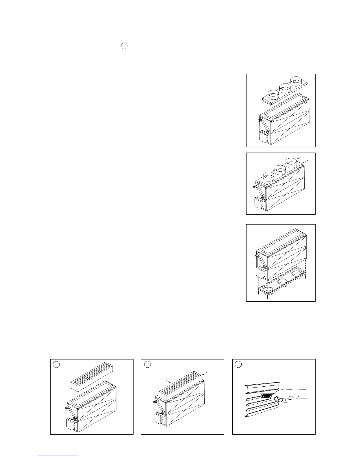
4.5 - AERAULIC CONNECTION
• The PA units are intended for installations with or without
ductwork.
4.5.1 - WITH DUCTINGS
• The unit is delivered with a rectangular blower connecting
spiggot.
• For the suction side, a filter kit with a rectangular connecting
spiggot is available separately. See accessories chapter.
4.5.2 - WITHOUT DUCTINGS
• Suction and blowing are posible directly in the premises.
4.5.3 - NOTE
• If access to the filter is difficult or impossible, (especially
if the clearance below the device is insufficient, as
mentioned in chapter 3.1), we recommend displacing the
filter to the offset air intake grille.
• To ensure correct operation, it is important that the
rated output be respected and to never fall below the
minimum output value (see curves in the technical
documentation).
Minimum
flow rate
600 m
3
/h
900 m
3
/h
Nominal
flow rate
850 m
3
/h
1200 m
3
/h
PA 188 C or R
PA 268 X or R
Standard
factory
installation
Other
possible
installation
configurations
Duct spiggot
(standard)
Suction
Suction
spiggot
with filter
(accessory)
Suction
spiggot
with filter
(accessory)
Duct spiggot
(standard)
Page 12

12
5 - INDOOR UNIT ACCESSORIES
5.1 - FILTER WITH SPIGGOT - Code K 60 V 220 T
• This accessory is mounted on the air intake (front or rear panel).
• It is secured by means of 6 screws (supplied).
• It can also be used as a simple rectangular duct connecting spiggot when the filter is not
installed.
• Spiggot thickness: 30 mm with filter, and 55 mm without filter.
5.2 - ELECTRIC HEATING
Code K 60 C 653 T : 3 kW for PA 188 C or R
Code K 60 C 656 T : 6 kW for PA 268 X or R
• The kit is essentially a separate heating unit which fits onto the
unit's exhaust.
5.2.1 - FITTING
• Place flange A onto the unit's duct spiggot.
• If required, taper the spiggot with a hammer so that it fits fully and
snugly onto the sleeve so that no air passes in the angles.
• Using the mounting flange as a guide, drill four Ø3 mm holes in the
unit's spiggot (one on each side).
• Secure the flange by the 4 sheetmetal screws (supplied).
• With the electrical connection boxes on the same side (on the left),
position the heating unit B onto the flange.
• Secure the heating unit with the 4 M8 nuts and bolts in the angles,
as well as the 4 securing clamps on the long sides of the unit (2 on
each side).
• Affix the adhesive foam strip (supplied) to complete the anticondensation insulation.
• The air outlet must be ducted to avoid direct contact with the
heating elements.
IMPORTANT:
• The heater kit is fitted with an automatic reset safety thermostat
(located on the resistors) and a manual reset safety thermostat.
• The original position of the thermostat bulb is intended for units
installed horizontally.
• If the unit is installed vertically, the bulb must be moved.
- Cut the plastic ties holding the bulb in place.
- Place the bulb on the wire conduit for the safety device of the
resistor which is the closest to the kit's outlet.
- Use the two plastic ties provided to secure it.
400V/3+Earth
230V/1+Earth
4 G 1.5 mm
2
3 G 2.5 mm
2
Section
4 G 2.5 mm
2
3 G 4 mm
2
3 kW 6 kW
400V/3
230V/1
4.5 A
13 A
9 A
26 A
3 kW 6 kW
MAINS SUPPLY
• Power to the heater kit must be supplied separately from that of
the air conditioning unit.
The power supply must be protected by a protective device and cutoff device (not supplied) in compliance with the regulations in force.
Caution: High-temperature resistant ties must be used (150°C minimum rating).
• To reset this safety device, refer to the chapter entitled "Maintenance Instructions".
• The sections are given as an indication only.
They must be checked and adapted to suit the installation conditions according
to existing standards.
• Pass the cable (not supplied) from the heater's electrical box into units box
through the available cable gland.
• Connect the cable to the kit’s terminal strip as shown in the wiring diagram in paragraph 12 (cable F ).
Heating unit B
Nuts and bolts
(M8) in corners
Clamps
Flange A
Duct spiggot
Drill 4 holes Ø 3 mm
Adhesive strip
to be affixed
after assembly
New bulb position
Plastic ties
Initial bulb location (cut plastic ties)
Resistor
Automatic
safety device
5.2.2 - ELECTRICAL CONNECTION
• See general recommendations in paragraph 4.4.
CHARACTERISTICS
• Power : 1 model 3 kW, 1 model 6 kW.
• Power supply 400V/3+Earth or 230V/1+Earth
• Current:
Power cable
Control cable
Page 13
13
CONTROL
• The kit comes with the control cable 3 G 1.5 mm2.
• Route this cable through a cable gland of the air-conditioner’s electrical box to the next terminal strip as shown in the wiring
diagram in paragraph 12 (cable G ).
NOTE: For the reversible models, set the remote control’s SC1 program switch on "0" (see paragraph 8.3.6).
5.3 - DELIVERY SIDE PLENUM WITH ROUND SPIGOTS
• Code K 60 M 019 Z : 3 spiggots, for PA 188 C and R.
• Code K 60 M 020 Z : 4 spiggots, for PA 268 X and R.
NOTE:
It is recommended that these 2 plenums be placed as shown (for adequate power per
outlet and air speed), although they can be mounded on both units.
• The plenum is to be mounted on the delivery side of the unit (directly or on the electric
heater kit).
• Remove the seals in located in the angles of the unit’s delivery sleeve.
• Place the plenum on top of the unit’s sleeve (or heater kit).
• Drill four Ø 3 mm holes in the unit’s sleeve (or heater kit) using the holes in the plenum
as a guide.
• Secure the plenum using the 4 sheet-metal screws provided.
5.5 - DOUBLE DEFLECTOR GRILLE
• Code K 60 M 029 Z.
• The grille is mounted on the delivery side of the unit (directly or on the electric heater kit) (figure 1).
• Place the grille on top of the unit’s sleeve (or heater kit) (figure 2).
• Drill four Ø 3 mm holes in the unit’s sleeve (or heater kit) using the holes in the grille as a guide (figure 2).
• Secure the grille using the 4 sheet-metal screws provided.
• Adjust the orientation of the fins using the sheet-metal wrench included in the kit (figure 3).
5.4 - AIRFLOW RETURN SIDE PLENUM WITH ROUND SPIGOTS
• Code K 60 M 049 Z : 3 spiggots, for PA 188 C and R.
• Code K 60 M 050 Z : 4 spiggots, for PA 268 X and R.
NOTE:
It is recommended that these 2 plenums be placed as shown (for adequate power per
outlet and air speed), although they can be mounded on both units.
• The plenum is installed on the airflow return side of the unit.
Caution: in the case, the filter kit cannot be used.
• Secure the plenum using the 4 sheet-metal screws provided.
1
2 3
Page 14

14
62021 122 N2
T°
12
11
1 2 3 4 5 6 N
S3
B1
S2 S1
acc
0
N (neutral)
L (phase)
Fan
COOL
HEAT
HS MS
LS
S3
S2
S1
B1
Remote
sensor
N (neutral)
L (phase)
HS
MSLS
S2
COOL
HEAT
Fan
speed
S1
B1
5.5 - REMOTE CONTROL (exclusively for cooling only models)
5.5.1 - PRESENTATION
Manual remote control - K 60 D 016 Z
S1 On/Off switch.
S2 Ventilation speed selector switch.
S3 Function selector switch.
B1 Room thermostat.
Automatic remote control - K 60 D 025 Z
Optional: a remote temperature sensor K 60 D 028 Z (simple) or K 60 D 033 Z (box) may be connected (see documentation
supplied with the sensors).
S1 ON/Off switch.
S2 Ventilation speed selector switch.
B1 Room thermostat.
5.5.2 - INSTALLATION OF THE BOX
A - PLACEMENT
• Approximately 1.50 m above floor.
• The box must be:
- easily accessible,
- unobstructed (away from curtains, cabinet, shelving,...).
• Avoid:
- any direct sunlight on the box (for example, opposite a window),
- exposure to drafts,
- placing the unit directly in the path of air blown by the air conditioner,
- fixing it on a badly insulated external wall,
- fixing it on a lightweight partition which can vibrate.
B - MOUNTING
• To remove the cover from the box, remove the thermostat knob and unscrew the mounting screw located behind it.
• Attach the base to the wall.
• Route the wiring through the back or from underneath the unit.
5.5.3 - ELECTRICAL CONNECTION
• Make the electrical connection with cable at least 0.75 mm2 (cable not supplied).
• Make the connections onto the terminal strip as shown in the wiring diagram in paragraph 12 (cable H ).
NOTE:
The control circuit for CP 188 C and 268 X models is protected by a 5 x 20 - 4 A - 250 V fuse (rated breaking power: 63 A)
located in the PA (see schematic diagrams).
Page 15

15
50
mini
(GR 268 R = 100)
170
mini
6 - OUTDOOR UNIT ACCESSORIES
6.2 - WALL SUPPORT for GRV 265 X - Code K 60 U 035 Z
1-After making sure that the fixing system used is suitable for the wall, fix the 2 vertical brackets to the wall.
Make sure that measurement 543 is correct.
2-Fit the 2 arms using the M8 screws provided.
3 - Put the unit on the arms:
- Put the anti-vibration pads between the supports and the feet of the unit.
- Fit the unit on the supports using the M8 screws supplied, making sure that the pads are not compressed too much
when tightening.
Wall
support
543
100100
6.1 - WALL SUPPORT for GRV 180 L, GR 188 R, GR 268 R - Code K 70 U 001 Z
1-After making sure that the fixing system used is suitable for the wall, fix the 2 vertical brackets to the wall.
Make sure that measurement A is correct.
2-Fit the 2 arms using the M8 screws provided.
3 - Fix the unit on the support using the M8 screws provided.
Wall
support
1
2 3
1
2 3
6.3 - HP PRESSURE SWITCH KIT for GRV 265 X only - Code K 60 G 093 Z
Cut-off value: 29 bar. Non-adjustable. Manual reset.
• Install the pressure switch directly on the discharge piping pressure tapping (see drawing page 16).
• Remove the jumper between terminals 5 and 6 of the accessories terminal strip and connect the two pressure switch wires
in their place.
A
100100
GRV180 L
GR 188 R
GR 268 R
A (mm)
538
538
620
Page 16
16
REL 7
REL 1
REL 4
REL 2
REL 3
KL3
KL1
REL 6
REL 5
6.4 - LP PRESSURE SWITCH KIT for GRV 265 X only - Code K 60 G 094 Z
7 - CONNECTING ACCESSORIES
8 - STANDARD CONTROL TYPE 523
Cut-off value: 0.5 bar. Non-adjustable. Automatic reset.
• Install the pressure switch directly on the suction piping pressure
tapping (see drawing opposite).
• If no HP pressure switch is already connected, remove the jumper
between terminals 5 and 6 of the main terminal strip and connect the two
pressure switch wires in their place.
• If the HP pressure switch is already connected between terminals 5 and
6 of the main terminal strip, disconnect the wire of terminal 6 and connect
it to a wire of the LP pressure switch, by using the double male lug
supplied with the LP kit. Connect the second wire of the LP pressure
switch on the terminal 6, now free.
Important: This connection must be made inside the electrical box.
6.5 - "PROPORTIONAL" HEAD PRESSURE CONTROL
for GRV 265 X only - Code K 60 G 012 Z
• Fix the controller directly on the pressure tapping point provided (see drawing above).
• Insert the cable into the electric equipment cabinet through a cable gland.
• Remove the jumper between terminals 3 and 4 of the main terminal strip and connect the two wires of the controller in its place.
Main terminal strip
LP pressure switch
HP pressure switch
Condensing
pressure regulator
Accessories
terminal strip
• Heat pump models only
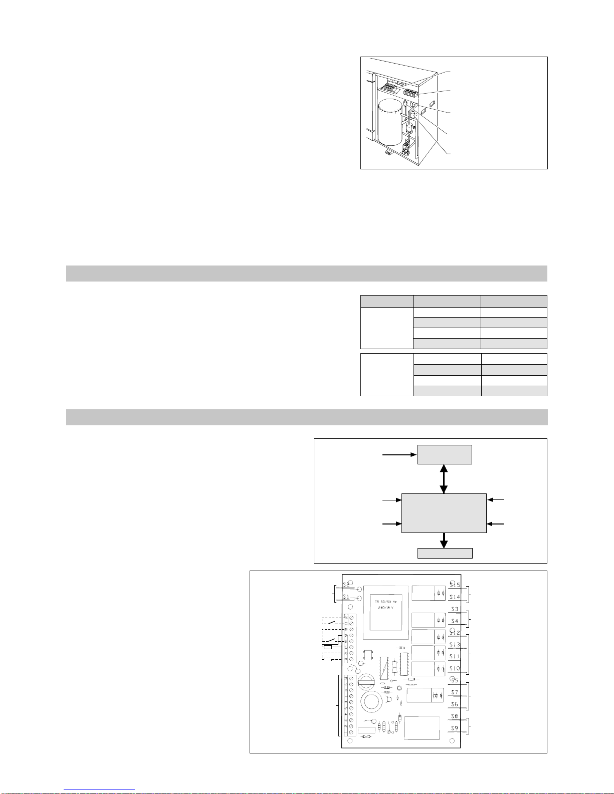
8.1 - PRINCIPLE
•The microprocessor manages the operation of the
air-conditioner.
• It constantly compares the ambient temperature with the
value displayed on the remote control. Each request for
operation processed by the controller is indicated by lights
7 and 8 (see paragraph 8.2.2).
These lights flash if a safety time delay is in progress.
It changes to a steady light when the unit is operating.
8.2 - PRESENTATION
8.2.1 - POWER SUPPLY CARD
• See wiring diagram for details on the
connections.
Remote
control
Electronic power
supply card
(in PA)
Actuators
Standby
contact
(possible)
Signalling
contact
(possible)
Remote ambient
thermoresistor
(option)
Defrosting sensor
(in GR-R)
Ambient
temperature
sensor
GR
fan control
PA
fan control
Cycle reverse
valve control
Compressor
control
Remote control
connection
Power supply 230 VAC
Defrosting sensor
Remote sensor
Make up
heating control
Standby
Signalling
7.1 - REFRIGERANT CONNECTIONS (for CP(V) 188 only)
Length CodeUnit
2 m
4 m
8 m
12 m
2 m
4 m
8 m
12 m
CPV 188 L
CP 188 R
CPV 188 L
CP 188 R
• These connections include the 2 insulated refrigeration lines.
7.2 - COMPLETE CONNECTION ASSEMBLIES
• These include: - the refrigeration lines,
- the electric cables,
-a condensate tube.
NOTE: The electric cables supplied in the connection assemblies cannot
be used for the reversible model.
K 70 A 02 BT
K 70 A 04 BT
K 70 A 08 BT
K 70 A 12 BT
K 70 A 02 BXT
K 70 A 04 BXT
K 70 A 08 BXT
K 70 A 12 BXT
Page 17

17
1
2
5678
13 12 11 10 9 3 15 14 4
KL1
KL2
SC1
P3
P2
P1
R26
IC1
1
00
0
0
1
0
1
0
1
0
1
0
1
0
1
0
111
Temperature °C
Rated ohmic value k
ΩΩ
ΩΩ
Ω
-10
-5
0
+5
+10
+15
+20
+25
+30
+35
187.034
142.602
109.587
85.279
66.785
52.330
41.272
33.000
26.281
21.137
Dimensions: Width : 130.5 mm
Height : 85 mm
Depth : 31 mm
8.2.2 - REMOTE CONTROL
A - FRONT PANEL
• Keys:
1 - Increase temperature set-point.
2 - Decrease temperature set-point.
3 - Air-conditioner operating mode selector.
4 - Ventilation operating mode selector.
• LED lights:
5 - Set-point temperature.
6 - Signalling (option).
7 - Operation in heating mode.
8 - Operation in cooling mode.
9 - "Standby" operating mode.
10 - "Automatic" operating mode (heating or cooling).
11 - "Ventilation only" operating mode.
12 - "Cooling only" operating mode.
13 - "Heating only" operating mode.
14 - "Automatic ventilation" mode.
15 - "Manual ventilation" mode (3 speeds).
B - INSIDE:
• Adjustment of differentials (see details in § 8-3):
- The neutral zone (between heating cut-off and cooling cutoff) is adjusted in the factory at 1K. P2 enables adjustment
up to 5 K.
-The difference between the triggering of the
thermodynamic heating and the possible make-up heating
is adjusted in the same way by P1.
- P3 is not used.
The adjustment of the potentiometers can only be done by
steps of 1 K. To do this, adjust the potentiometers on marks 1,
2, 3, 4 or 5.
For the intermediate positions, the electronics automatically
select the following whole value.
8.2.3 - TEMPERATURE SENSORS
Type CTN - 33 k
ΩΩ
ΩΩ
Ω (± 5%) at 25°C
8.3 - OPERATION
8.3.1 - TEMPERATURE ADJUSTMENT OPERATING
DIAGRAM
• Hysterisis of control signals: 0.6K to 1
K
• Set-point tolerance: ± 2.5
K
• Tolerance of neutral zone: ± 0.3
K
NOTE:
The cycle inversion valve is activated in heating mode.
Microprocessor
Connection pins
Temperature sensor
Potentiometer
Adjustment of differentials
BCD switch of programs
(for electric heating, set to position 0)
MS
MS
HS
HS
LS LS
Set-point
Valve
control
Compressor
control
in cooling
Compressor
control
in heating
Control of
possible
make-up
Ventilation control
in automatic mode
Boost
triggering differential
adjustable from
1 to 5K by P1
Neutral zone
adjustable from 1 to 5K by P2
Page 18

18
8.3.2 - OPERATING MODES
• The 5 available operating modes:
- Standby (indicated by yellow LED 9)
- Automatic (indicated by red LED 10)
- Ventilation only (indicated by red LED 11)
- Cooling only (indicated by red LED 12)
- Heating only (indicated by red LED 13)
• When powered up, the device is set at "Standby". In this mode, all the controller’s outputs are deactivated and the air-
conditioner is not is service. Only light 9 is lit.
• All mode selections on key 3 (by pressing it successively) are immediately indicated by a LED.
However, the device does not take into account the modification of the mode until after about 3 seconds.
Consequently, when rapidly going through the different modes, the device does not take into account the intermediate modes
and stays at its initial status.
A - AUTOMATIC MODE
• In this mode, the Cooling and Heating functions are selected automatically according to the difference between the set-point
and the ambient temperature (see preceding diagram).
• The set-point corresponds to the point where the compressor stops when in heating mode.
• The activated operating mode is indicated by light 7 for Heating and 8 for Cooling. These lights flash if a safety time delay
is in progress. They change to steady light when the unit is operating.
B - VENTILATION MODE ONLY
• In this mode, only the PA ventilator is in operation.
• The Heating/Cooling control is deactivated.
C - COOLING MODE ONLY
• In this mode, only the Cooling is in operation.
• The device does not heat.
• The cycle inversion valve is not activated.
D - HEATING MODE ONLY
• In this mode, only the Heating is in operation.
• The device does not cool.
• The cycle inversion valve is activated permanently.
8.3.3 - PA VENTILATION OPERATING MODES
• Two operating modes are available:
- Automatic (indicated by red LED 14)
- Manual (indicated by red LEDs 15)
A - AUTOMATIC VENTILATION MODE
• This mode is selected by the control as soon as it switches from "Standby" mode to "Automatic" mode, by pressing key 3.
• In this ventilation mode:
- ventilation speed is selected automatically according to the difference between the set-point and the ambiant temperature,
- ventilation stops when in the neutral zone between cold and hot,
- in HEATING and COOLING only modes, the ventilator is cut off at the point where these two functions are stopped,
- in VENTILATION ONLY, the operation is the same as for Cooling only, i.e. the ventilator is cut-off if the temperature falls
below the SET-POINT + NEUTRAL ZONE value.
B - MANUAL VENTILATION MODE
• This mode is selected by pressing key 4.
• In this mode, the ventilation operates continuously at the speed selected (3 speeds).
• It is possible to switch back to automatic ventilation mode by pressing on key 4 again.
NOTE: Stopping the ventilation of the PA is delayed by 1 minute after stopping in Heating mode to ensure the evacuation
of residual heat.
8.3.4 - SET-POINT ADJUSTMENT
• The set-point is adjusted by using the + and - keys (references 1 and 2). The adjustment range is from 16 to 30°C.
• At each press, the LED display shifts by one position to the right (increase temperature) when pressing the + key or to the
left (decrease temperature) when pressing the - key.
• In STANDBY mode all the LED’s of the scale are off. By selecting any mode by using the push-button on the left, the display
will light and correspond to the last value selected.
• When first powering up and after selecting the operating mode, the value displayed is automatically 22
°C.
• This is also the case after power has been cut-off for a period of 4 hours.
• As the control is equipped with a back-up accumulator, the display will indicate the last value selected after power
has been restored if the cut-off period is less then 4 hours.
Page 19

19
8.3.5 - ANTI-SHORT CYCLE COMPRESSOR
• To avoid over-frequent starting-up of the compressor and thus increase its lifetime, a 3 minute time delay is triggered every
time the compressor is activated.
• If the temperature varies suddenly during this time delay to the point of calling for heating or cooling, or if the set-point is
changed in the same proportions, the LED for the corresponding demand starts flashing, indicating that the anti-short cycle
has been activated.
It is only after this time delay has run-out that the control activates the corresponding output, after which the LED lights
normally.
8.3.6 - OUTDOOR UNIT DEFROSTING
• The De-frosting cycle starts when the external sensor
assembled on the unit detects a temperature ≤ -3°C and
stops when the temperature reaches +20°C or after a
maximum of 10 minutes.
• After de-frosting, a time delay prevents a new cycle for a
period of either 30 minutes, or 60 minutes. The selection
of the time delay is done by a jumper between terminals
2 and 6 of terminal strip KL1 (see above).
• During this time delay, the de-frosting cycle cannot restart
if the temperature falls below -3°C.
• The status of the relays during the defrosting can be
selected according to two variants:
- Air-conditioner without auxiliary heating (factory configuration)
(SC1 program switch set at position 1 on the remote control).
• If the temperature of the external sensor reaches
-3°C, the device switches to the de-frosting
function and the status of the relays will be as
follows (see table opposite).
• The PA ventilator stops, thus avoiding cold air
currents.
• To indicate that the device is in De-frosting mode,
the two cooling and heating demand LED’s 7 and
8 start flashing alternatively.
- Air-conditioner with auxiliary heating
(SC1 program switch on the remote control set at position 0).
8.3.7 - SAVING DURING POWER CUTS
• An accumulator installed on the power supply card permits saving the configuration during power cuts (operating mode,
ventilation mode, set-point).
• When restoring power, the control automatically returns to the previous configuration.
• However, to avoid incorrect switching, the outputs are activated only 20 seconds afterwards, permitting the device to measure
the current ambiance.
• The accumulator cannot save the data for a period longer than 4 hours after which they will be lost.
The device will be set at Standby after restoring power.
• The accumulator is fully charged when the device has been powered up for 3 days.
• If the temperature of the external sensor reaches
-3°C, the device triggers the defrosting cycle and
the status of the relays is therefore as follows (see
table opposite).
• Starting the auxiliary heating during the de-frosting
cycle prevents over-cooling the room.
• To indicate that the device is in De-frosting mode,
the two cooling and heating demand LED’s 7 and
8 start flashing alternatively.
Relay
REL 3
REL 2
REL 4/5/6
REL 1
REL 7
Status
energized
de-energized
de-energized
de-energized
de-energized
Function
Compressor in continuous operation
Reversal valve in Cooling position
Internal ventilator stopped
--External ventilator stopped
Relay
REL 3
REL 2
REL 4
REL 1
REL 7
REL 5/6
Status
energized
de-energized
energized
energized
de-energized
de-energized
Function
Compressor in continuous operation
Reversal valve in Cooling position
Internal fan on slow speed
Auxiliary heating activated
External fan stopped
MS and HS inhibited
Defrosting sensor
No jumper between 2 and 6: 30 mn
Jumper between 2 and 6: 60 mn
END OF DEFROSTING CYCLE
• If the temperature of the external sensor reaches +20°C or at maximum after 10 minutes, the device switches to normal
operation. The LED’s stop flashing and all the functions resume normal operation.
•A new de-frosting cycle cannot start until after a period of 30 or 60 minutes.
NOTE: During defrosting, if the operating mode is changed by pressing key 3, the defrosting stage stops before the appliance
starts in the required mode. If the appliance has been switched to standby remotely, the defrosting stage stops after
15 seconds.
To ensure smooth air-conditioner operation, we recommend against changing the operating mode and
stopping the appliance when in a defrosting stage.
Page 20
20
9 - STARTING
9.1 - PRELIMINARY CHECKS
• Make sure:
- that the refrigerant fittings are correctly tightened and that the two shut-off valves are open,
- that there are no leaks,
- that the indoor and outdoor unit are well fixed,
- that the power cables are well fixed to their connection terminals. Loose terminals can cause heat build-up on the terminal
board,
- that the electric cables are properly insulated from any pieces of sheet or metal parts which could damage them,
- that the unit is connected to earth,
- that no tools or any other objects have been left in the units,
- that the filter is correctly fitted,
- that the condensate discharge outlet is correctly connected.
IMPORTANT
Before doing any work on the installation, make sure it is switched off and put out of bounds;
Pay particular attention to the heater kit which is powered separately.
All operations must be carried out by personnel that are approved and qualified for this type of equipment.
8.4 - STARTING THE CONTROL
CHECKS TO BE CARRIED OUT
• This paragraph only concerns the control.
• For all measures and precautionary steps to be taken when starting up the air-conditioner, refer to § 9.
1 - Power-up the controller.
2 - Press mode selection key 3.
3 - Adjust the set-point by pressing keys +/- 1
and 2.
4 - Press mode selection key 3.
5 - Press ventilation selection key 4.
6 - Press ventilation selection key 4.
7 - Press ventilation selection key 4.
8 - Press mode selection key 3.
9 - Press mode selection key 3.
10 - Press mode selection key 3.
The STANDBY light 9 illuminates after 20 seconds.
The control switches to Automatic mode. Lights 10 and 14
illuminate.
If heating or cooling are called, the corresponding lights 7 and 8
illuminate.
The temperature scale light 5 illuminates at the desired value.
The control switches to Ventilation only mode.
The corresponding light 11 illuminates.
Heating and cooling do not function.
Ventilation shifts to continuous slow speed.
The corresponding light 15 illuminates.
Select medium then high speed.
The corresponding light illuminates.
The ventilation switches back to Automatic mode.
The corresponding 14 light illuminates.
The controller switches to Cooling only mode. The corresponding
light 12 illuminates.
If cooling is called light 8 illuminates (it flashes if a safety time delay
is in progress).
The controller switches to Heating only mode. The corresponding
light 13 illuminates.
If heating is called light 7 illuminates (it flashes if a safety time delay
is in progress).
The controller returns to Standby. The corresponding light 9
illuminates. The other lights extinguish.
Page 21

21
10 - MAINTENANCE INSTRUCTIONS
• Air filter:
- We recommend that the air filter be cleaned every 2 weeks by
compressed air or water.
See the "User's Manual".
- Remove the filter by pulling the cartridge as shown in the
diagram.
• External unit air exchanger:
- Cleaning recommended once a year.
• Electric connections:
- Once a year, check that the electric wires are well fastened to
their terminals.
• Electric boxes:
- Dusting is recommended once a year.
• Electric heating safety
- The heating kit is equipped with automatic resetting safety
thermostats (located on the resistors) and a manual reset safety
device.
- The manual reset is used in case of nonexistent or weak air flow.
Possible causes:
- faulty fan motor,
- turbines blocked or jammed,
- clogged filter,
- heat exchanger excessively dirty,
- air intake, outlet or ducts blocked.
- Correct the malfunction then reset the safety thermostat located
under the electrical box by removing the cap and pressing the
button as shown.
1 2
Resetting
button
IMPORTANT
Before doing any work on the installation, make sure it is switched off and put out of bounds.
Pay particular attention to the heater kit which is powered separately.
All operations must be carried out by personnel that are approved and qualified for this type of equipment.
Cap
9.2 - SWITCH ON THE UNIT
• Using the isolation and protection device.
9.3 - START THE UNIT
• Using the indoor unit's control panel (see paragraph 8.4 for reversible models).
9.4 - VENTILATION OF OUTDOOR UNIT
• All all-season usage, the GRV180 L is equipped with a condensation pressure control system as standard.
Ventilation motor speed varies according to the outside air temperature and the temperature of the outdoor exchanger.
Page 22
22
16
18
20
26
28
22
24
14
-824-6 -4 -2 0 2 4 6 8 10 12 14 16 18
20 22
-8
24
1
2
3
4
-6 -4 -2 0 2 4 6 8 10 12 14 16 18
20 22
5
14 16 18 20 22 24
11
13
15
17
19
21
23
25
14 16 18 20 22 24
0
1
2
3
4
5
6
7
14 16 18 20 22 24
11
13
15
17
19
21
23
25
14 16 18 20 22 24
0
1
2
3
4
5
6
7
High pressure (relative bar)
Inside wet bulb temperature (°C)
Low pressure (relative bar)
Inside wet bulb temperature (°C)
High pressure (relative bar)
Inside wet bulb temperature (°C)
Low pressure (relative bar)
Inside wet bulb temperature (°C)
High pressure (relative bar)
Outside wet bulb temperature (°C)
Low pressure (relative bar)
Outside wet bulb temperature (°C)
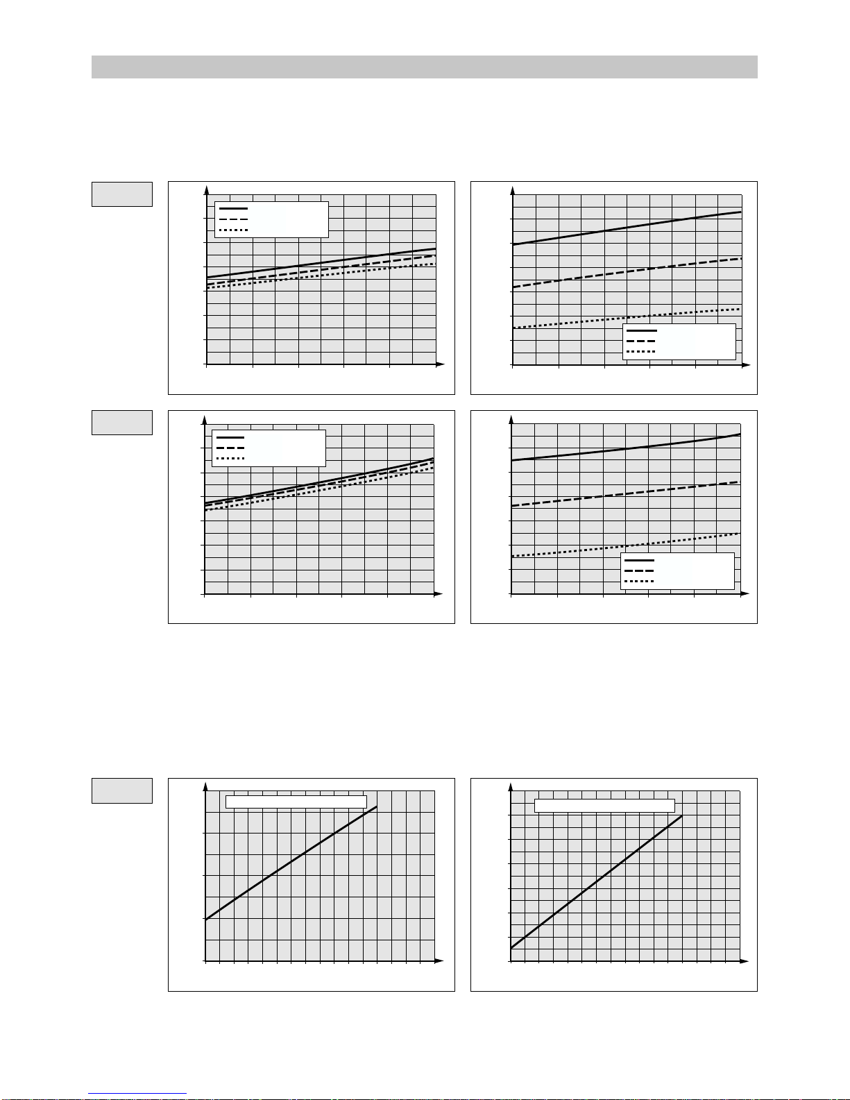
11.1.2 - HEATING MODE
HIGH PRESSURE
LOW PRESSURE
Inside temperature = 20°C
CP 188 R
CP 268 R
CP 188 R
Inside temperature = 20°C
Out. temp. = 43°C
Out. temp. = 35°C
Out. temp. = 19°C
Out. temp. = 43°C
Out. temp. = 35°C
Out. temp. = 19°C
Out. temp. = 43°C
Out. temp. = 35°C
Out. temp. = 19°C
Out. temp. = 43°C
Out. temp. = 35°C
Out. temp. = 19°C
11 - PRESSURE CURVES
11.1.1 - COOLING MODE
11.1 - R 22 MODELS
HIGH PRESSURE
LOW PRESSURE
Page 23

23
12
14
16
22
28
18
20
24
26
10
30
-824-6 -4 -2 0 2 4 6 8 10 12 14 16 18
20 22
1
2
3
6
7
4
5
0
-824-6 -4 -2 0 2 4 6 8 10 12 14 16 18
20 22
HIGH PRESSURE
LOW PRESSURE
11.2 - R 407 C MODELS (cooling only)
HIGH PRESSURE
LOW PRESSURE
High pressure (relative bar)
Outside wet bulb temperature (°C)
Low pressure (relative bar)
Outside wet bulb temperature (°C)
CPV 268 X
CP 268 R
Inside temperature = 20°C
Inside temperature = 20°C
14 16 18 20 22 24
11
13
15
17
19
21
23
25
14 16 18 20 22 24
3
4
5
6
High pressure (relative bar)
Inside wet bulb temperature (°C)
Low pressure (relative bar)
Inside wet bulb temperature (°C)
Out. temp. = 43°C
Out. temp. = 35°C
Out. temp. = 19°C
Out. temp. = 43°C
Out. temp. = 35°C
Out. temp. = 19°C
CPV 188 L
14 16 18 20 22 24
11
13
15
17
19
21
23
25
14 16 18 20 22 24
3
3.5
4
4.5
5
5.5
6
6.5
7
High pressure (relative bar)
Inside wet bulb temperature (°C)
Low pressure (relative bar)
Inside wet bulb temperature (°C)
Out. temp. = 43°C
Out. temp. = 35°C
Out. temp. = 19°C
Out. temp. = 43°C
Out. temp. = 35°C
Out. temp. = 19°C
Page 24

24
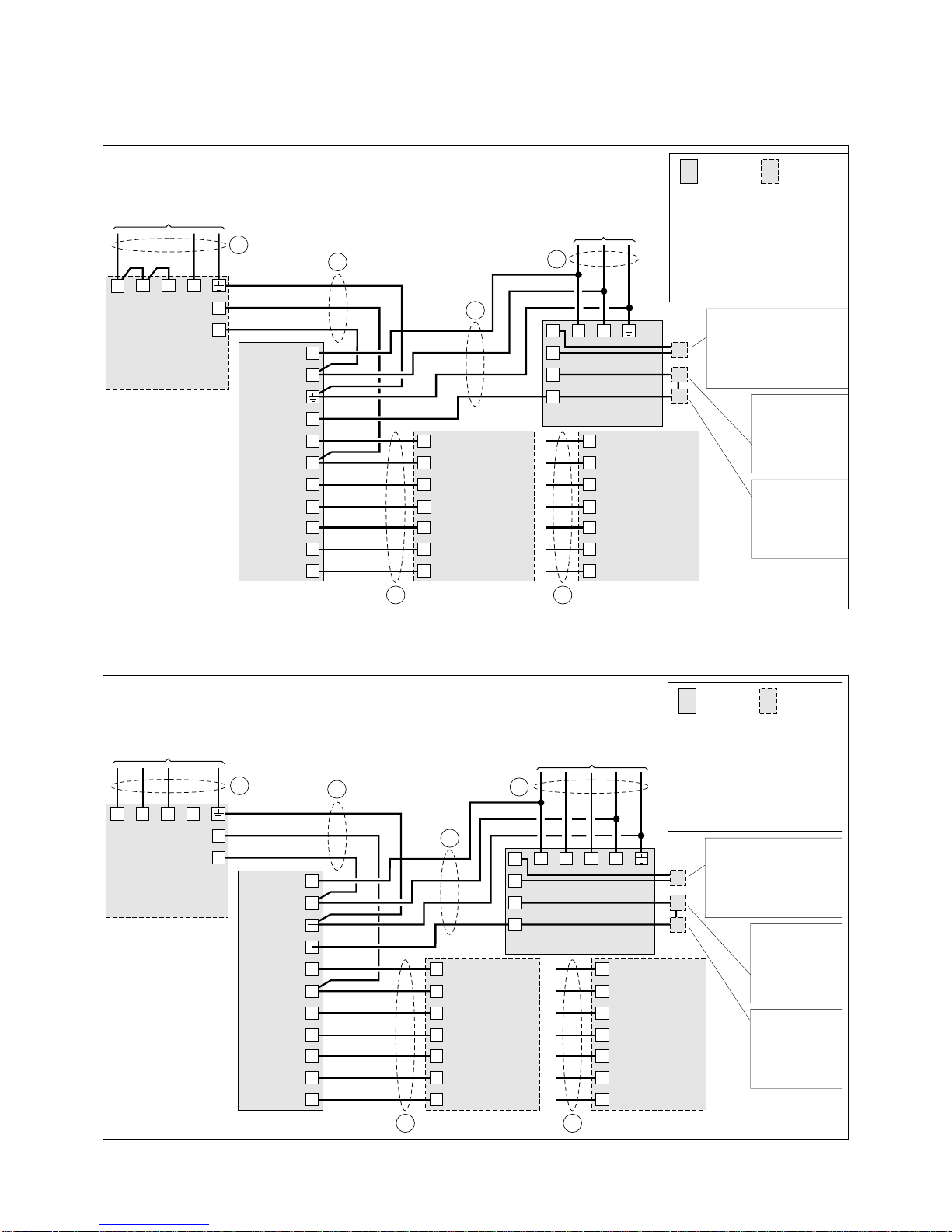
B
Bleu
Blue
Blu
Azul
Blau
Standard
Standard
Standard
Estándar
Standard
Accessoire
Accessory
Accessorio
Accesorio
Zubehör
V/J
Vert/Jaune
Green/Yellow
Verde/Giallo
Verde/Amarillo
Grn/Gelb
M
Marron
Brown
Marrone
Marrn
Braun
C
5
1
2
11
12
31
32
33
PA 188 C
230/1/50
4
6
Commande à distance
Remote control
Comando a distanza
Mando a distancia
Fernsteuerung
K 60 D 016 Z
2
6
N
3
5
4
1
V/J
M
B
Alimentation kit chauffage
Power heater kit
limentazione kit riscaldamento
A
limentacin kit de calefaccin
Stromversorgung der Heizung
400 V / 3 / 50 Hz
26
22
Kit chauffage
Electric heater kit
Kit riscaldamento
Kit de calefacción
Elektrisch Heizung
N
3 kW = K 60 C 653 T
6 kW = K 60 C 656 T
U
V W
1
4
L3 L2
GRV 180 L
400/3N/50
A
Alimentation gnrale
Mains supply
Alimentazione generale
Alimentacin elctrica
Stromversorgung
400 V / 3 N / 50 Hz
2
L1
N
Commande à distance
Remote control
Comando a distanza
Mando a distancia
Fernsteuerung
K 60 D 025 Z
6
2
1
N
22
21
20
H H
G
F
Commande à distance
Remote control
Comando a distanza
Mando a distancia
Fernsteuerung
K 60 D 016 Z
2
6
N
3
5
4
Commande à distance
Remote control
Comando a distanza
Mando a distancia
Fernsteuerung
K 60 D 025 Z
6
2
1
N
22
21
20
1
4
L N
GRV 180 L
230/1/50
A
C
5
1
2
11
12
31
32
33
PA 188 C
230/1/50
4
6
Alimentation gnrale
Mains supply
Alimentazione generale
Alimentacin elctrica
Stromversorgung
230 V / 1 / 50 Hz
Monter le pont livr avec le kit.
Connect the bridge with the wire included in the kit.
Montare il ponte consegnato con il kit.
Montar el puente suministrado con el kit.
Die mit der elektrischen Heizung mitgelieferte Brcke installieren.
1
2
H H
Standard
Standard
Standard
Estándar
Standard
Accessoire
Accessory
Accessorio
Accesorio
Zubehör
V/J
Vert/Jaune
Green/Yellow
Verde/Giallo
Verde/Amarillo
Grn/Gelb
M
Marron
Brown
Marrone
Marrn
Braun
B
Bleu
Blue
Blu
Azul
Blau
V/J
M
B
Alimentation kit chauffage
Power heater kit
Alimentazione kit riscaldamento
Alimentacin kit de calefaccin
Stromversorgung der Heizung
230 V / 1 / 50 Hz
Kit chauffage
Electric heater kit
Kit riscaldamento
Kit de calefacción
Elektrisch Heizung
U
V W N
3 kW = K 60 C 653 T
6 kW = K 60 C 656 T
26
22
G
F
*
*
230V/1/50Hz to CONNECTION CPV 188 L
400V/3N/50Hz to CONNECTION CPV 188 L
12 - ELECTRICAL CONNECTION DIAGRAMS
Page 25
25
Standard
Standard
Standard
Estándar
Standard
Accessoire
Accessory
Accessorio
Accesorio
Zubehör
V/J
Vert/Jaune
Green/Yellow
Verde/Giallo
Verde/Amarillo
Grn/Gelb
M
Marron
Brown
Marrone
Marrn
Braun
B
Bleu
Blue
Blu
Azul
Blau
Commande à distance
Remote control
Comando a distanza
Mando a distancia
Fernsteuerung
K 60 D 016 Z
2
6
N
3
5
4
Commande à distance
Remote control
Comando a distanza
Mando a distancia
Fernsteuerung
K 60 D 025 Z
6
2
1
N
22
21
20
U V
GRV 265 X
400/3N/50
A
C
5
1
11
12
31
32
33
PA 268 X
230/1/50
4
6
Alimentation gnrale
Mains supply
Alimentazione generale
Alimentacin elctrica
Stromversorgung
400 V / 3N / 50 Hz
V/J
M
B
1
2
5
3
4
Alimentation kit chauffage
Power heater kit
limentazione kit riscaldamento
limentacin kit de calefaccin
Stromversorgung der Heizung
400 V / 3 / 50 Hz
26
22
3 kW = K 60 C 653 T
6 kW = K 60 C 656 T
Kit chauffage
Electric heater kit
Kit riscaldamento
Kit de calefacción
Elektrisch Heizung
N
6
Rgulation toutes saisons
Head pressure control
Regolazione tutte le stagioni
Regulacin todas estacione
s
Drehzahlgeregelt
K 60 G 012 Z
Pressostat BP
LP pressure switch
Pressostato BP
Presstato BP
ND-Pressostat
K 60 G 094 Z
Pressostat HP
HP pressure switc
h
Pressostato AP
Presstato AP
HD-Pressostat
K 60 G 093 Z
U
V W
N
W
HH
BP
HP
G
F
Commande à distance
Remote control
Comando a distanza
Mando a distancia
Fernsteuerung
K 60 D 016 Z
2
6
N
3
5
4
Commande à distance
Remote control
Comando a distanza
Mando a distancia
Fernsteuerung
K 60 D 025 Z
6
2
1
N
22
21
20
1 N
GRV 265 X
230/1/50
A
C
1
11
12
31
32
33
PA 268 X
230/1/50
4
6
Alimentation gnrale
Mains supply
Alimentazione generale
Alimentacin elctrica
Stromversorgung
230 V / 1 / 50 Hz
V/J
M
B
1
2
5
3
4
Alimentation kit chauffage
Power heater kit
limentazione kit riscaldamento
limentacin kit de calefaccin
Stromversorgung der Heizung
230 V / 1 / 50 Hz
26
22
3 kW = K 60 C 653 T
6 kW = K 60 C 656 T
Kit chauffage
Electric heater kit
Kit riscaldamento
Kit de calefacción
Elektrisch Heizung
U
V W N
6
Standard
Standard
Standard
Estándar
Standard
Accessoire
Accessory
Accessorio
Accesorio
Zubehör
V/J
Vert/Jaune
Green/Yellow
Verde/Giallo
Verde/Amarillo
Grn/Gelb
M
Marron
Brown
Marrone
Marrn
Braun
B
Bleu
Blue
Blu
Azul
Blau
Rgulation toutes saisons
Head pressure control
Regolazione tutte le stagioni
Regulacin todas estaciones
Drehzahlgeregelt
K 60 G 012 Z
Pressostat BP
LP pressure switch
Pressostato BP
Presstato BP
ND-Pressostat
K 60 G 094 Z
Pressostat HP
HP pressure switch
Pressostato AP
Presstato AP
HD-Pressostat
K 60 G 093 Z
H H
BP
HP
F
G
Monter le pont livr avec le kit.
Connect the bridge with the wire included in the kit.
Montare il ponte consegnato con il kit.
Montar el puente suministrado con el kit.
Die mit der elektrischen Heizung mitgelieferte Brcke installieren
.
5
*
*
230V/1/50Hz to CONNECTION CPV 268 X
400V/3N/50Hz to CONNECTION CPV 268 X
Page 26

26
Standard
Standard
Standard
Estándar
Standard
Accessoire
Accessory
Accessorio
Accesorio
Zubehör
V/J
Vert/Jaune
Green/Yellow
Verde/Giallo
Verde/Amarillo
Grün/Gelb
M
Marron
Brown
Marrone
Marrón
Braun
B
Bleu
Blue
Blu
Azul
Blau
Commande à distance
Remote control
Comando a distanza
Mando a distancia
Fernsteuerung
C
3
2
1
13
15
PA 188 R
PA 268 R
230/1/50
V/J
M
B
Alimentation kit chauffage
Power heater kit
Alimentazione kit riscaldamento
Alimentación kit de calefacción
Stromversorgung der Heizung
230 V / 1 / 50 Hz
26
22
3 kW = K 60 C 653 T
6 kW = K 60 C 656 T
Kit chauffage
Electric heater kit
Kit riscaldamento
Kit de calefacción
Elektrisch Heizung
U
V W N
A
Alimentation générale
Mains supply
Alimentazione generale
Alimentación eléctrica
Stromversorgung
230 V / 1 / 50 Hz
2
N L
GR 188 R
GR 268 R
230/1/50
1
6
4
5
8
7
D
Sonde dégivrage
Defrost sensor
Sonda sbrinamento
Sonda desescarche
Enteisungssonde
4
3
2
1
7
6
5
9
8
4
3
2
1
7
6
5
10
9
8
10
14
12
11
17
16
18
E
Sonde à distance
Remote sensor
Sonda a distanza
Sonda a distancia
Externe Temperatursonde
K 60 D 028 Z
ou / or / o / o / oder
K 60 D 033 Z
Marche/Arrêt à distance (hors fourniture)
Remote On/Off (not supplied)
Avviamento/Arresto a distanza (non fornito)
Funcionamiento/Parada a distancia (no suministro)
Ein/Aus Ferngesteuert (nicht mitgeliefert)
Alarme (hors fourniture)
Alarm (not supplied)
Allarme (non fornito)
Alarma (no suministro)
Alarm (nicht mitgeliefert)
Carte électronique placée dans le coffret électrique
Electronic card inserted in the electric box
Scheda elettronica posta nel cofano elettrico
Tarjeta electrónica colocada en el armarion eléctrico
Elektronikkarte im Schaltkasten
G
F
6
4
5
Monter le pont livré avec le kit.
Connect the bridge with the wire included in the kit.
Montare il ponte consegnato con il kit.
Montar el puente suministrado con el kit.
Die mit der elektrischen Heizung mitgelieferte Brücke installieren
.
*
*
ou, or, o, o, oder 3
230V/1/50Hz to CONNECTION CP 188 R / 268 R
Page 27

27
Commande à distance
Remote control
Comando a distanza
Mando a distancia
Fernsteuerung
C
3
2
1
13
15
PA 268 R
230/1/50
V/J
M
B
Alimentation kit chauffage
Power heater kit
Alimentazione kit riscaldamento
Alimentación kit de calefacción
Stromversorgung der Heizung
400 V / 3 / 50 Hz
26
22
3 kW = K 60 C 653 T
6 kW = K 60 C 656 T
Kit chauffage
Electric heater kit
Kit riscaldamento
Kit de calefacción
Elektrisch Heizung
U
N
A
Alimentation générale
Mains supply
Alimentazione generale
Alimentación eléctrica
Stromversorgung
400 V / 3N / 50 Hz
2
N
GR 268 R
400/3N/50
1
6
4
5
8
7
D
Sonde dégivrage
Defrost sensor
Sonda sbrinamento
Sonda desescarche
Enteisungssonde
4
3
2
1
7
6
5
9
8
4
3
2
1
7
6
5
10
9
8
10
14
12
11
17
16
18
E
Sonde à distance
Remote sensor
Sonda a distanza
Sonda a distancia
Externe Temperatursonde
K 60 D 028 Z
ou / or / o / o / oder
K 60 D 033 Z
Marche/Arrêt à distance (hors fourniture)
Remote On/Off (not supplied)
Avviamento/Arresto a distanza (non fornito)
Funcionamiento/Parada a distancia (no suministro)
Ein/Aus Ferngesteuert (nicht mitgeliefert)
Alarme (hors fourniture)
Alarm (not supplied)
Allarme (non fornito)
Alarma (no suministro)
Alarm (nicht mitgeliefert)
Carte électronique placée dans le coffret électrique
Electronic card inserted in the electric box
Scheda elettronica posta nel cofano elettrico
Tarjeta electrónica colocada en el armarion eléctrico
Elektronikkarte im Schaltkasten
V W
L
1
L3L
2
Standard
Standard
Standard
Estándar
Standard
Accessoire
Accessory
Accessorio
Accesorio
Zubehör
V/J
Vert/Jaune
Green/Yellow
Verde/Giallo
Verde/Amarillo
Grün/Gelb
M
Marron
Brown
Marrone
Marrón
Braun
B
Bleu
Blue
Blu
Azul
Blau
6
4
5
F
G
400V/3N/50Hz to CONNECTION CP 268 R
Page 28
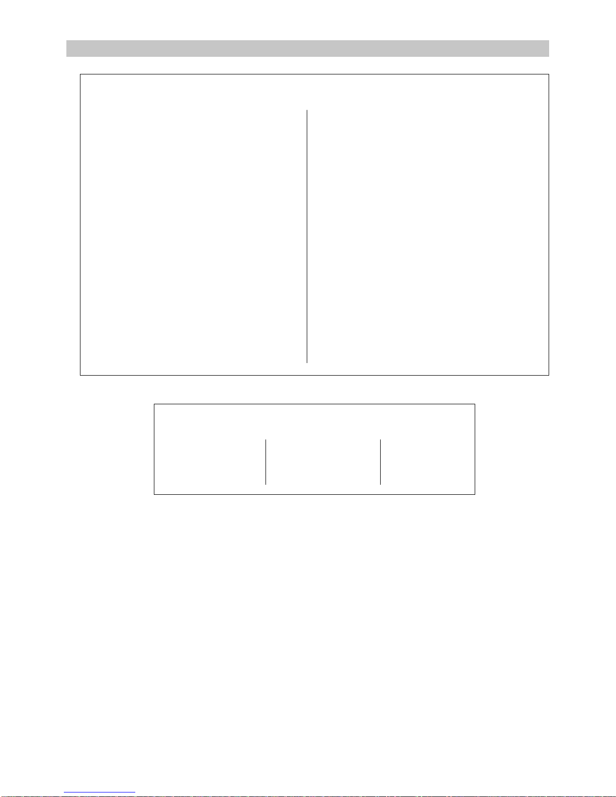
28
13 - WIRING DIAGRAMS
B Blue
G Grey
J Yellow
JV Yellow/Green
SYMBOLS OF COMPONENTS
A1 Control board
B1 Anti-frost thermostat
B2 Thermal safety
B3 Thermal safety
C1 Fan capacitor
C2 Compressor capacitor
C3 Filtration capacitor
C4 Starting capacitor
C5 Starting capacitor
CCH Crankcase heater
CM Compressor
EV1 Cycle reverse valve
F1 Control circuit fuse
F2 Internal safety compressor
FM Fan
K2 Compressor contactor
KA1 Auxiliary relay
KA2 Auxiliary relay
KM1 Fan contactor
KM2 Compressor contactor
KM3 Heating contactor
KM4 Heating contactor
NPR Phase sequence relay
PCB Electronic card
POW-CL Filter
PR1 Fan relay
Q1 Control circuit circuit-breaker
RO Crankcase heater
R1 Electric heater
R2 Electric heater
R3 Electric heater
R4 Electric heater
R5 Electric heater
R6 Electric heater
SD1 Defrosting sensor
SSR Electronic card
T Thermostat
TH1 Air temperature sensor
TH2 Exchanger air temperature sensor
TP Terminal board
TR Transformer
COLOURS OF THE WIRES
L Purple
M Brown
N Black
NW Black/White
O Orange
P Pink
R Red
W White
Page 29

29
10 05 665 - 00
PA 188 C / PA 268 X - 230/1/50
10 05 666 - 00
PA 188 R / PA 268 R - 230/1/50
1234567891011121314151617181920
A
B
C
D
E
F
G
H
I
J
K
L
M
ALIMENTATION 230V/1/50
POWER SUPPLY 230V/1/50
VENTILATION
FAN MOTOR
M1
C1
4
6
5
3
2
1
L
N
R
11
12
13
14
15
16
17
18
3849
10 11 13
14 15
12
765
112
2
3
3
44556677889
9
10
10
Ventilation / Fan
intérieure
indoor
extérieure
outdoor
Vanne
Valve
Compresseur
Compressor
Chauffage électrique
Electric heating
B1
KA1
G
T
KA2
1
2
B
M
M
R
PVLSMVMSGV
HS
G (PA 268)
N (PA 268)
R
W
W
KA2
O
KA1
Sonde à distance / Remote sensor
Sonde dégivrage / Defrost sensor
M/A à distance / Remote ON/OFF
Alarme / Alarm
Commande VENTILATION EXTERIEURE
OUTDOOR UNIT FAN control
Commande VANNE / VALVE Control
Commande COMPRESSEUR / COMPRESSOR Control
Commande CHAUFFAGE / HEATING Control
COMMANDE A DISTANCE
REMOTE CONTROL
CARTE DE CONTROLE
CONTROL CARD
A1
43
M (PA 188)
G (PA 188)
1234567891011121314151617181920
A
B
C
D
E
F
G
H
I
J
K
L
M
2
11
6
31
32
33
12
4
T
5
1
PE
XA
XA
XA
XA
XA
XA
XA
XA
XA
XA
XA
F1
B1
M1
C1
4A 250V
5x20
W
N (PA 268 ) G (PA 188 )
G (PA 268 ) M (PA 188)
R
N
N
3
4
PVLSMVMSGV
HS
1
~
W
M
W
M
ALIMENTATION 230V/1/50
POWER SUPPLY 230V/1/50
VENTILATION
FAN MOTOR
Commande COMPRESSEUR / COMPRESSOR Control
Commande CHAUFFAGE / HEATING Control
Page 30

30
GRV 180 L - 400/3N/50
1
2
4
L1
L2
L3
N
L3L2L1 N
CM
(C)T
R
S
JV
N
B
W
R
J
G
TSR 13
A
B
78
JV
WV U14
WU
R
W
M
P
JV
T
S
R
A
C
FM
W
B
R
M
G
G
JV
M
G
R
R
W
B
P
F2
CCH
NPR
TP
C1
P
M
N
PO2
2
TH2
(COIL)
N
N
2
11
SP
N
N
THC2
THC1
PO1
P
TH1
(AIR)
N
N
22
11
SP
G
G
THR2
THR1
PCB
FU1
P
W
W
P2
P1
SP
M
M
S2
S1
W
W
M
M
P
S
TR
JV
3
4
5
12
2
2
11
22
11
21
21
S
P
G
N
G
G
78
5
3
1
3
4
5
O
J
P
12
SSR
O
LL
R
PR1
W
KM2
S
R
S1 S2
R1 R3
JV
POW-CL
Connecteur 2P (vert)
Connector 2P (green)
Connecteur 2P (bleu)
Connector 2P (blue)
Connecteur 2P (blanc)
Connector 2P (white)
Connecteur 2P (rouge)
Connector 2P (red)
Connecteur 2P (jaune)
Connector 2P (yellow)
Unité intérieu re
Indoor unit
Alimentation 400/3N/50
Power supply 400/3N/50
CCH
GG
N
O
W
G
1
2
4
L
N
TP
JV
N
JV
JV
21
2121
S
TR
P
M
M
W
W
M
M
S
P
PCB
S2
S1
21
W
W
S
P
P2
P1
21
G
G
S
P
THR121THR2
N
N
TH1
PO1
FU1
543
P
R
21
N
N
S
P
THC121THC2
N
N
FU2
2
1
11
22
PS
N
G
N
G
N
PO2
L
O
J
P
8
N
10
KM2
24
6
G
CM
S
R
C
C2
W
N
JV
R
78
PR1
5
1
3
L
2
1
3
4
5
SSR
L
R
FM
C1
P
M
W
JV
JV
TH2
Unité intérieu re
Indoor unit
Alimentation 230/1/50
Power supply 230/1/50
Connecteur 2P (blanc)
Connector 2P (white)
Connecteur 2P (rouge)
Connector 2P (red)
Connecteur 2P (jaune)
Connector 2P (yellow)
Connecteur 2P (bleu)
Connector 2P (blue)
Connecteur 2P (vert)
Connector 2P (green)
GRV 180 L - 230/1/50
Page 31

31
10 05 458 - 03
GRV 265 X - 400/3N/50
M2
M2
M1
C1
C3
K2
K2
RO
3~
1~
312
S
R
C
JV
1
2
3
N
L
NW
L
N
11
12233
JV
BB
NMNW
U
V
W
N
5
3
4
6
T1
T2
T3
Raccordement PA
Connection PA
Alimentation 400/3N/50
Power supply 400/3N/50
10 05 457 - 06
GRV 265 X - 230/1/50
M2
M2
M1
K2
K2
RO
1~
1
~
NBM
S
R
C
JV
M
N
L
NW
L
N
MM
NMN
JV
B
BB
NM
M
N
NW
1
N
5
3
4
6
C1
C3
C2
Raccordement PA
Connection PA
Alimentation 230/1/50
Power supply 230/1/50
Page 32
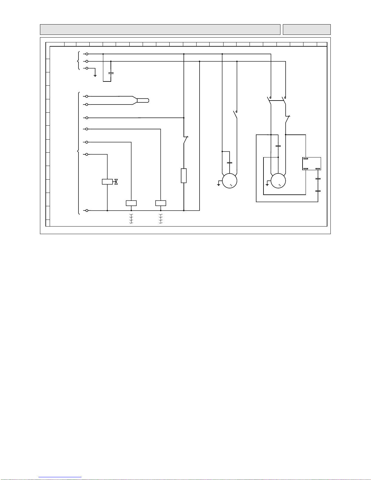
32
10 05 690 - 01
GR 188 R - 230/1/50
1
M1
M2
R
S
C
C3
W
PMW
G
N
W
R
KM2
F2
KM2
N
W
KM1
N
W
XA
L
XA
XA
N
N
W
N
XA
2
A
B
N
A1
A2
KM2
R1
KM1
EV1
5 6
3 4 3 4
1 2 1 2
- -
- -
(01-12)
(01-12) (01-16)
- -
(01-16 )
(01-16)
U
14
W
(01-6)
(01-8)
11
T
C1
C2
C5
C4
KA1
1
SD1
R
L1
2
3
M
L
K
J
I
H
G
F
E
D
C
B
A
123456789101112131415 1617181920
XA
XA
XA
1
7
8
R
XA
XA
XA
4
5
6
G
M
Unité intérieure
Indoor unit
Alimentation protégée
230V/1+T/50
Power supply
230V/1+Earth/50
Page 33

33
10 05 663 - 00
GR 268 R - 400/3N/50
1
M1
M2
C3
W
PM
G
NWR
KM2
R
N
W
KM1
1
R
B
N
XA
XA
XA
L1
L3
L2
XA
XA
N
B
R
N
W
N
B
Q1
5 A
123
4
XA
XA
XA
1
7
8
R
XA
XA
XA
4
5
6
G
W
N
XA
2
A1
A2
N
A
B
KM2
KM1
EV1
5 6
3 4 3 4
1 2 1 2
- -
- -
(01-12)
(01-12) (01-16)
- -
(01-16 )
(01-16)
2U4
W
V
(01-6) (01-8)
3
T
S
S
C
R
M2
C1
RNW
1
M
L
K
J
I
H
G
F
E
D
C
B
A
1234567891011121314151617181920
SD1
Raccordement compresseur
Compressor connection
Unité intérieure
Indoor unit
Alimentation protégée
230V/1+T/50
Power supply
230V/1+Earth/50
10 05 662 - 00
GR 268 R - 230/1/50
1
M1
M2
R
SC
C3
W
PM
G
NWR
KM2
B
N
KM1
1
R
B
N
XA
L
XA
XA
N
B
N
N
B
Q1
5 A
123
4
XA
XA
XA
1
7
8
R
XA
XA
XA
4
5
6
G
W
N
XA
2
A1
A2
N
A1
A2
KM2
KM1
EV1
5 6
3 4 3 4
1 2 1 2
- -
- -
(01-12)
(01-12) (01-16)
- -
(01-16 )
(01-16)
2U4
W
V
(01-6) (01-8)
3
T
S
S
C
R
M2
C1
C2
RNW
1
M
L
K
J
I
H
G
F
E
D
C
B
A
1234567891011121314151617181920
SD1
Raccordement compresseur
Compressor connection
Unité intérieure
Indoor unit
Alimentation protégée
230V/1+T/50
Power supply
230V/1+Earth/50
Page 34
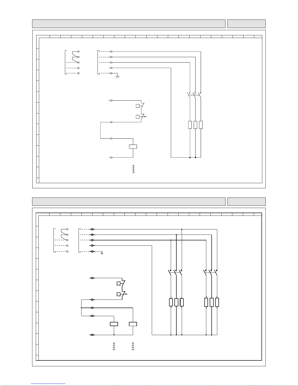
34
1234567891011121314151617181920
A
B
C
D
E
F
G
H
I
J
K
L
M
1 2
3 4
5 6
13 14
(01-16)
(01-16)
(01-16)
- -
1 2
3 4
5 6
13 14
(01-12)
(01-12)
(01-12)
- -
(01-9) (01-7)
XA
W
XA
V
XA
U
XA
N
XA
26
XA
22
XA
23
XA
24
XA
25
KM3
A1
A2
B3
T
B2
T
KM4
A1
A2
R1
KM4
12345
6
R2
R3
R4
KM3
12345
6
R5
R6
M
M
M
R
O
L
N
N
B R
WWW
WWW
XA
PE
Alimentation / Power supply
400/3/50
230/1/50
W
V
U
N
PE
10 05 667 - 00
KIT CHAUFFAGE ELECTRIQUE /
ELECTRIC HEATING KIT
- 6 kW - 230/1/50 - 400/3/50
10 05 678 - 00
KIT CHAUFFAGE ELECTRIQUE /
ELECTRIC HEATING KIT
- 3 kW - 230/1/50 - 400/3/50
1234567891011121314151617181920
A
B
C
D
E
F
G
H
I
J
K
L
M
1 2
3 4
5 6
13 14
(01-16)
(01-16)
(01-16)
- -
(01-9)
XA
W
M
O
O
WWW
L
N
BR
M
M
R
XA
V
XA
U
XA
N
XA
PE
XA
26
XA
22
XA
23
XA
25
KM3
A1
A2
B3
T
B2
T
R1
KM3
12345
6
R2
R3
Alimentation / Power supply
400/3/50
230/1/50
W
V
U
N
PE
Page 35

35
R.D. 28 Reyrieux BP 131 01601 Trévoux CEDEX France
Phone 33 4 74 00 92 92 - Fax 33 4 74 00 42 00
R.C.S. Bourg-en-Bresse B 759 200 728
Due to our policy of continuous development, our products are liable to modification without notice.
 Loading...