

Page 1

F
NOTICE D’UTILISATION • OPERATING INSTRUCTIONS
ISTRUZIONI D’USO • INSTRUCCIONES DE USO
BEDIENUNGSANLEITUNG
CAW INVERTER
GB
I
E
D
Unités terminales • Terminal units
Unità terminali • Unidades terminales
Endgeräte
37.4254.063.01 01/2015
Page 2

CONTENTS
NAME OF PARTS AND OPERATION SELECTOR SWITCH 3
INSTALLATION LOCATION 4
ELECTRICAL REQUIREMENTS 4
SAFETY INSTRUCTIONS 4
USING THE REMOTE CONTROL UNIT 4
REMOTE CONTROL UNIT 5
HOW TO SET THE PRESENT TIME 6
COOLING 6
HEATING 6
AUTOMATIC OPERATION 6
DOUBLING SPEED FUNCTION 6
DEHUMIDIFYING (DRY) 7
FAN ONLY 7
ADJUSTING THE FAN SPEED 7
ECONOMY MODE 7
HIGH POWER MODE 7
SETTING THE TIMER 7
SETTING THE 1 HOUR TIMER 8
SETTING THE HOLIDAY TIMER 8
ADJUSTING THE AIR FLOW DIRECTION 8
OPERATION WITHOUT THE REMOTE CONTROL UNIT 9
CARE AND CLEANING 9
TIPS FOR ENERGY SAVING 11
TROUBLESHOOTING 11
LEDS’ TABLE 12
GB
PRODUCT INFORMATION
If you have problems or questions concerning your Air
Conditioner, you will need the following information. Model
ALERT SYMBOLS
The following symbols used in this manual, alert you
to potentially dangerous conditions to users, service
personnel or the appliance:
and serial numbers are on the nameplate on the bottom
of the air conditioner.
Model No. .........................................................................
Serial No. ..........................................................................
Date of purchase ..............................................................
Dealer’s address ..............................................................
Phone number ...................................
This symbol refers to a hazard or unsafe practice which
can result in severe personal injury or death.
This symbol refers to a hazard or unsafe practice which can
result in personal injury or product or property damage.
WARNING
CAUTION
NOTE
This terminal unit is equipped with cooling, drying, heating and fan only functions.
Details on these functions are provided below; refer on these descriptions when using the terminal unit.
DECLARATION OF CONFORMITY
This product is marked as it satisfies Directives:
– Low voltage no. 2006/95/CE. (Standard: EN60335-2-40:2003 (incl. Corr.:2006) + A11:2004 + A12:2005 + A13:2012
+ A1:2006 + A2:2009 con EN 60335-1:2002 + A11:2004 + A1:2004 + A12:2006 + A2:2006 + A13:2008 + A14:2010
+ A15:2011).
– Electromagnetic compatibility no. 2004/108/CE, 92/31 EEC and 93/68 EEC. (Standard: EN55014-1 (2006) +
A1(2009) + A2(2011), EN 55014-2 (1997) + A1(2001) + A2 (2008), EN 61000-3-2 (2006) + A1(2009) + A2(2009),
EN 61000-3-3 (2008)
– RoHS2 no.2011/65/EU.
This declaration will become void in case of misuse and/or non observance though partial of manufacturer’s
installation and/or operating instructions.
2
Page 3

NAME OF PARTS AND OPERATION SELECTOR SWITCH
15
GB
12
14
13
10
3
2
1
1. Remote control unit.
2. Remote control sensor: Detects the room temperature
around the remote control unit, the air conditioner is
controlled accordingly.
3. Air outlet: Conditioned air is blown out of the air
conditioner through the air outlet.
Air intake: Air from the room is drawn into this section
4.
and passes through air filter which removes dust.
5. Remote control receiver: This section picks up infrared
signals from the remote control unit (Transmitter).
6. Operation selector (without remote control): Push
the button to walk through the OFF, COOL and HEAT
operation modes.
8. STANDBY lamp: This lamp lights up when the air
conditioner is connected to the power and ready to
receive the remote control command.
5
6
4
5
7 9 8
TIMER STBY
OPER
11
6
5
7 9 8
7. OPERATION lamp: This lamp lights up during
operation.
It blinks once to announce that the remote controlsignal
has been received and stored. It blinks continuously
during the protection modes (defrosting, etc.).
9. TIMER lamp: This lamp lights up when the system is
being controlled by the timer.
10. Air intake latch, on two sides.
11. Air filter.
12. Suspension brackets.
13. Refrigerant couplings.
14. Condensate drain connection.
15. Sensor: Detects the room temperature around the
unit; when the remote control unit is not active the air
conditioner will be set by the detected temperature.
WARNING
The OFF position does not disconnect the power. Use
the main power switch to turn off power completely.
INFORMATION FOR CORRECT DISPOSAL OF THE PRODUCT IN ACCORDANCE WITH THE EUROPEAN DIRECTIVE
2012/19/EU
At the end of its working life this equipment must not be disposed of as an household waste.
It must be taken to special local community waste collection centres or to a dealer providing this service.
Disposing of an electrical and electronic equipment separately avoids possible negative effects on the environment
and human health deriving from an inappropriate disposal and enables its components to be recovered and recycled
to obtain significant savings in energy and resources.
In order to underline the duty to dispose of this equipment separately, the product is marked with a crossed-out dustbin.
INFORMATION FOR CORRECT DISPOSAL OF THE BATTERY IN ACCORDANCE WITH THE EUROPEAN DIRECTIVE
2006/66/EC
Please replace battery when its electricity charge is used up: please do not eliminate this battery together with normal household
waste. It must be taken to special local community waste collection centres or to a dealer providing this service. Disposing of a
battery separately avoids possible negative effects on the environment and human health deriving from an inappropriate disposal
and enables its components to be recovered and recycled to obtain significant savings in energy and resources. In order to underline
the duty to dispose of this equipment separately, the battery is marked with a crossed-out dustbin.
NOTE
The blinking of OPERATION, TIMER and STANDBY
lamps, indicates that the operating mode selected
is not compatible with the unit. If this happen the air
conditioner does not operate until the correct mode
is selected.
3
Page 4

INSTALLATION LOCATION
l
We recommend this air conditioner to be installed
properly by qualified installation technicians in
accordance with the installation instructions
provided with the unit.
WARNING
l
Do not install this air conditioner where there are
fumes or flammable gases, or in an extremely humid
space such as a green house.
l
Do not install the air conditioner where excessively
high heat-generating objects are placed.
l
Do not install the air conditioner where the
atmosphere is extremely damp or humid (e.g.
greenhouse or laundry) it could be wetted by drops
of water (i.e. in laundries).
ELETRICAL REQUIREMENTS
l
Before installation, check that the voltage of the electric
supply in your home or office is the same as the voltage
shown on the nameplate.
l
All wiring must conform to the local electrical codes.
Consult your dealer or a qualified electrician for details.
l
Each unit must be properly grounded with a ground (or
earth) wire or through the supply wiring.
l
Wiring must be done by a qualified electrician.
SAFETY INSTRUCTIONS
l
Read this booklet carefully before using this air
conditioner. If you still have any difficulties or
problems, consult your dealer for help.
l
This air conditioner is designed to give you
comfortable room conditions. Use this only for its
intended purpose as described in this Instruction
Manual.
l
Insert two AAA alkaline batteries of 1,5 V-DC making
sure that point in the direction marked in the battery
compartment.The displayed time flashes.
Press the SEL TYPE button.
Remote controller is now ready for operation.
l
The batteries last about six months. Depending on how
much you use the remote control unit.
Remove the batteries if you do not use the remote
control unit for more than one month.
Replace the batteries when the remote control unit
lamp fails to light, or when the air conditioner does not
receive the remote control unit signals.
l
The batteries of the remote control contain polluted
substances exhausted batteries must be disposed
according to the laws in force.
HOW TO REMOVE BATTERIES
l Remove the lid.
l Press the battery toward the negative end and lift it out
by its positive end (as shown in the figure).
l Remove the other battery in the same way.
GB
WARNING
l
Never use or store gasoline or other flammable vapor or
liquid near the air conditioner. It is very dangerous.
l
Never install electrical equipment, which is not
protected with IPX1 protection (protection against
vertical water drop), under the unit.
l
The manufacturer assumes no responsabilities if the
safety regulations or local codes are not observed.
CAUTION
l
Never use the power main switch to start or stop the
air conditioner: always use the ON/OFF button on the
remote control unit or the selector switch on the unit.
l
Do not stick anything into the air outlet of the air
conditioner. This is dangerous because the fan is
rotating at high speed.
l
Do not let children play with the air conditioner.
l
Do not cool the room too much if babies or invalids
are present.
USING THE REMOTE CONTROL UNIT
HOW TO INSTALL BATTERIES
l Remove the lid in the rear part of the remote control
unit and check the settings of the dipswitch as shown
below:
TEMPERATURE SENSOR SELECTOR
l
Under normal conditions the room temperature is
detected and checked by the temperature sensor placed
in the remote controller (I FEEL icon displayed ).This
function is designed to provide a comfortable room
temperature by transmitting the temperature control
command from the location next to you. When using this
function, the remote, control should always be pointed
at the air conditioner, therefore it should be placed in
a position in which it is visible by the indoor unit (for
example, do not put it in a drawer).
l
It is possible to disable the remote controller room
sensor pressing the I FEEL button. In this case the I
FEEL icon on the remote controller display lights off and
the sensor placed in the air conditioner becomes active.
NOTE
The remote control unit transmits signals to the
indoor unit each time you press a key and at any
temperature change detected by the IFEEL sensor. In
case of troubles (low batteries, remote control placed
in a position not visible by the indoor unit,...) room
temperature control is automatically switched to the
sensor of the indoor unit. In this case, the temperature
around the remote control unit may differ from the
temperature detected in the air conditioner position.
SWITCHES
OPERATION WITH THE REMOTE CONTROL UNIT
When using the remote control unit, always point the unit
transmitter head directly at the air conditioner receiver.
HOW TO TURN ON THE AIR CONDITIONER
Press the ON/OFF button to turn the air conditioner on.
The operation lamp will light up, indicating the unit is in
operation.
4
Page 5

GB
REMOTE CONTROL UNIT
DISPLAY
Information is displayed when the remote controller is
switched on. If switched off, only the operating mode, the
room temperature and the clock are shown
Operation mode
Automatic
Cooling
Heating
Dehumidification
Fan
Economy
mode
Oscillation
Flap
HIGH POWER
mode
C
Fan speed
I FEEL mode is active
(remote controller sensor active)
Disables the temperature error that can not be
reached
Displayed when transmitting data
Timer modes
Clock
Automatic
High speed
Medium speed
Low speed
Room
temperature
Set point
temperature
MODE SELECTOR BUTTON
Press this button to modify the unit mode.
(cooling)
The unit makes the room cooler.
(dry)
The unit reduces the humidity in the room.
(automatic)
The unit makes the room cooler adjusting
the setpoint according to the perceived
temperature.
(fan)
The unit works only as a
circulation fan.
Press the button until no icon is
displayed, then adjust the type of
ventilation with the FAN button.
TEMPERATURE SETTING BUTTONS
- (cooler)
Press this button to decrease the set
temperature.
+ (warmer)
Press this button to increase the set
temperature.
SENSOR
A temperature
sensor inside the
remote control unit
detects the room
temperature.
TRANSMITTER
When you press
the buttons of the
remote control unit,
the mark
appears on the
display to transmit
the setting changes
to the receiver in the
unit.
C
MODE SELECTOR BUTTON
Press this button to modify the unit mode.
(heating)
The unit makes the room warmer.
(automatic)
The unit makes the room warmer adjusting the
setpoint according to the perceived temperature.
ON/OFF BUTTON
This button turns the unit ON and OFF.
FLAP BUTTON
Press this button in order to select the desired
function.
Fixed: six position
“FAN “ BUTTON (fan speed)
Fan speed is automatically
selected by the microcomputer.
High speed.
Medium speed.
Low speed.
ECONOMY MODE BUTTON
Press this button in order to select the
NIGHT/ECO mode.
“HIGH POWER” BUTTON
Press this button in order to select the
HIGH POWER mode.
CLOK AND TIMER SETTING BUTTON
Press this button in order to:
• set the clock
• set the ON/OFF timer
For details refer to paragraphs “SETTING
THE HOUR” and “SETTING THE TIMER”.
HOURS AND MINUTES SETTING
BUTTONS
With these buttons is possible to set the
clock and the timer. For details refer to
paragraphs “ SETTING THE HOUR” and
“SETTING THE TIMER”.
5
Continous oscillations
Automatically oscillations
IFEEL SENSOR SELECTOR
Press this button to modify the active setting
for room temperature detection (from remote
controller to unit and viceversa).
CLEAN BUTTON
Press this button to disable the error “Set
temperature can not be reached” (see
DIAGNOSTICS’ TABLE) and to set modbus
address (see section “MODBUS CONNECTION”.
TIMER SELECTION BUTTON
Press this button to select the type of timer to
activate. For details refer to paragraph
“SETTING
THE TIMER”.
Page 6

HOW TO SET THE PRESENT TIME
AUTOMATIC OPERATION
1. Press the button ST three times.
The time indication alone flashes.
2. Press the SET H button until the present time hour
is displayed. Press the SET M button until the
present time minutes are displayed. The display
will automatically stop flashing.
COOLING
NOTE
Verify that the unit is connected to the
main power and the STANDBY lamp is
light up.
1. Set the selector to COOL (symbol
on the display).
2. Press the +/- buttons (temperature
selection) to set the desired temperature
(the temperature range is between 32 °C
max. and 10 °C min.).
THE DISPLAY SHOWS THE
SELECTED TEMPERATURE.
C
1
2
3
1
1. Set the or selector to AUTO (symbol on
the display; also the symbol or remains
displayed).
2. Press the
+/- buttons (temperature selection)
to set the
desired temperature (the temperature range is between
32 °C max. and 10 °C min.).
THE DISPLAY SHOWS THE
SELECTED TEMPERATURE.
AFTER 5 SECONDS FROM THE
REQUIRED TEMPERATURE SETTING
GB
THE DISPLAY WILL SHOW THE ROOM
TEMPERATURE AGAIN.
2
When selecting “auto cooling” or “auto heating”
operation, the unit is set respectively in cooling or heating
mode adjusting the room temperature understood as
“perceived”. The perceived temperature depends on
the value of the room relative humidity, according to the
“humidex” index.
3. Press the FAN selector button to the setting you want.
EXAMPLE: if the sensors indicate a temperature of 30°C
and a relative humidity of 50%, the temperature really
perceived by the human body is 36°C and the unit will
adjust the temperature according to this last value.
AFTER 5 SECONDS FROM THE
REQUIRED TEMPERATURE SETTING
THE DISPLAY WILL SHOW THE ROOM
TEMPERATURE AGAIN.
3. Press the FAN button to select the fan speed.
HEATING
1. Set the selector to HEAT (symbol on the display).
2. Press the +/- buttons (temperature selection) to set the
desired temperature (the temperature range is between 32
°C max. and 10 °C min.).
THE DISPLAY SHOWS THE
SELECTED TEMPERATURE.
AFTER 5 SECONDS FROM THE
REQUIRED TEMPERATURE SETTING
THE DISPLAY WILL SHOW THE ROOM
TEMPERATURE AGAIN.
3. Press the FAN button to select the fan speed.
DOUBLING SPEED FUNCTION
This function allows to double the available fan speed,
slowing the fan automatically when the room temperature
is close to the set one.
To enable this function, follow the steps below:
1. Select the following settings on the remote control
unit:
• “Auto cooling” function
• Flap AUTO
• Set temperature 10°C
2. Simultaneously press and hold the I FEEL and FAN
buttons for at least 7 seconds.
3. Release the I FEEL and FAN buttons pointing the
remote control unit at the unit’s receiver. 3 beeps will
signal you that the function is active and the operation
led, when the unit is on, will flash with a frequency of
2 seconds ON, 2 seconds OFF.
4.
Select again the desired setting.
NOTE
For several minutes after the start of heating operation, the
indoor fan will stop until the indoor heat exchanger coil has
warmed up sufficiently. This is because the COLD DRAFT
PREVENTION SYSTEM is operating. During this period,
the STANDBY lamp remains lit.
H
H-
M
M-
L
L-
LL
LL-
1°C0 1,5°C 2°C
6
50rpm
∆T
Page 7

GB
DEHUMIDIFYING (DRY)
1. Set the button to DRY. The icon is displayed.
2. Press the
+/- buttons (temperature selection)
to set the
desired temperature (the temperature range is between
32 °C max. and 10 °C min.).
THE DISPLAY SHOWS THE
SELECTED TEMPERATURE.
AFTER 5 SECONDS FROM THE
REQUIRED TEMPERATURE SETTING
THE DISPLAY WILL SHOW THE ROOM
TEMPERATURE AGAIN.
NOTE
l
Use DRY operation when you want to reduce the humidity
in the room.
l
Once the room temperature reaches the set level, the unit
repeats the cycle of turning on and off automatically.
l
During DRY operation, the fan speed is automatically
set (Remote control lamp is ON) to prevent
overcooling.
l
Dry operation is not possible if the indoor temperature is
10 °C or less.
FAN ONLY
If you want to make air circulate without any temperature
control, press button until only the fan symbol
appears on the display.
NOTA
The fan is forced to the minimum speed and the setpoint
is increased/reduced automatically by 2,5°C in cooling/
heating respectively.
HIGH POWER MODE
When this mode is active the fan is forced to the maximum
speed and the setpoint is automatically adjusted to 32°C
in heating mode and 10°C in cooling mode.
NOTE
During the high power operation the room temperature
could not correspond to the set temperature.
SETTING THE TIMER
A) HOW TO SET THE ON TIME
1. Press the ST button once.
The ON and time indications flash.
2. Press the H button until the designed
hour is displayed.
Press the M button until the designed
minutes are displayed. The display
will change automatically back to
show the present time after 10 sec.
3. Press the ON/OFF button to start the
air conditioner.
4. Press the button to activate the
ON timer.
C
3
ADJUSTING THE FAN SPEED
AUTOMATIC
Simply set the FAN selector to the position.A
microcomputer automatically controls the fan speed when
the AUTO mode is selected. When the air conditioner
starts operating, in heating or cooling, the fan speed varies
(high - medium - low - very low) according to the thermal
load of the room.
NOTE
The automatic speed is not available in FAN ONLY mode.
MANUAL
If you want to manually adjust speed just set the FAN
selector as desired.
High speed Med. speed Low speed
ECONOMY MODE
l
This mode enables you to save energy.
1. Set the or selector to cool, dry or heat.
B) HOW TO SET THE OFF TIME
1. Press the ST button twice.
The OFF and time indications flash.
2. Press the H button until the designed
hour is displayed.
Press the M button until the designed
minutes are displayed. The display will
change automatically back to show
the present time after 10 sec.
3. Press the ON/OFF button to start the
air conditioner.
4. Press the button two times to
activate the OFF timer.
C) HOW TO SET A PROGRAM FOR
DAILY ON/OFF OPERATION (OR
VICEVERSA)
1. Set the timer ON/OFF as shown in A)
and B).
2. Press the ON/OFF button to start the
air conditioner.
3. Press three times the button to
activate the DAILY timer.
2
2
1
4
2. Press the button.
3. The mark appears on the display. Press the
button again to release the function.
NOTE
After timer setting, press ST button in order to check the
ON/OFF setting time.
7
Page 8
SETTING THE 1 HOUR TIMER
This function causes the unit to operate for one hour at the
set conditions, regardless of whether the unit is on or off.
TIMER SETTING PROCEDURE.
l
Press four times the button.The 1
HOUR TIMER mark will appear on the
display.
CANCELLATION PROCEDURE
l
Press the ON/OFF button to turn the air conditioner off.
l
Wait for the indoor unit to stop operating.
l
Press the ON/OFF button again to turn the air conditioner
on.
SETTING THE HOLIDAY TIMER
The Holiday Timer function allows you to activate the
indoor unit (either it is the only one of a monosplit system
or one unit of a multisplit system), with a dalay up to
99 days you can set for the Daily Timer, On Timer, Off
Timer functions (not available for 1 HOUR TIMER) already
explained in this manual.
With this function you can set the air conditioner to be
switched on again after a long week end, a holiday of one
week or more, ecc…
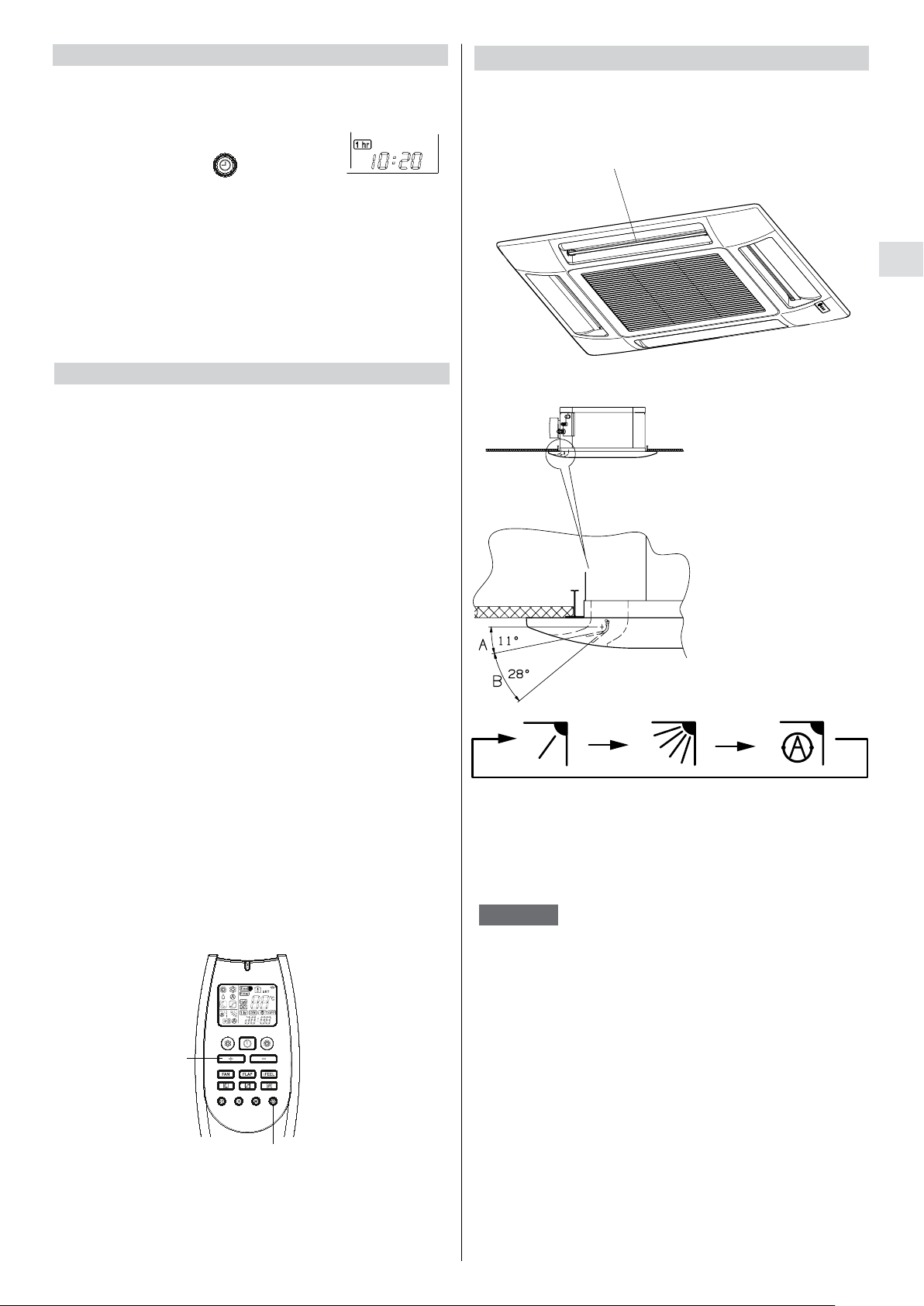
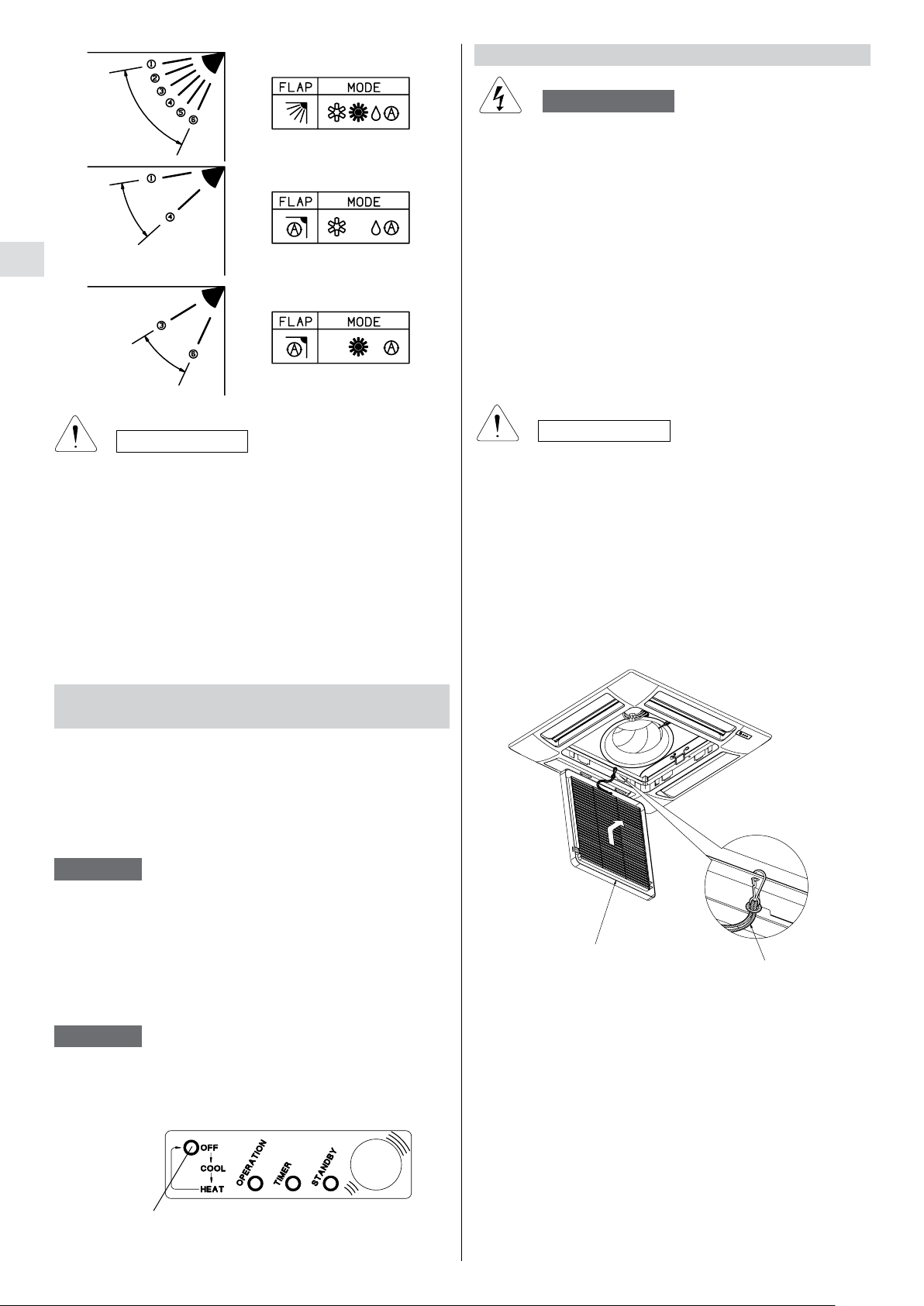
ADJUSTING THE AIR FLOW DIRECTION
You can adjust the air flow direction using the 4 flaps of
the grille frame. Chose the best position according to the
operation mode and the recommended flap position.
FLAPS
GB
HOW TO ADJUST THE FLAP DIRECTION
Zone «A»
for cooling and dehumidifyng
Zone «B»
for heating
To activate this function you have to follow the following
steps in order :
1. Keep pressed the button “TIMER SELECTION” of the
remote control unit (clock figure) for more than 6~7
seconds. In this way you enter the menu to select the
number of days of delay.
2. Select the desired timer (Daily Timer, On Timer,
Off Timer) pressing on the same button “TIMER
SELECTION”.
3. Set the desired number of days of delay using the
button “+” .
4. Keep pressed again the button “TIMER SELECTION”
for more than 6~7 seconds. You enter again the normal
menu of the remote control unit.
At this point, the symbol of the desired timer will flash
and the selected timer will be activated only after the set
number of delay days.
C
Fixed:
position
NOTES
six
Continous
oscillations
Automatically
oscillations
• The flap automatically closes when the unit
is off.
During heating operation, the fan is off and
•
the flap is in fixed position. Once the air
warms up, the flap position and fan speed
change according to the settings specified
with the remote control
.
3
1 - 2 - 4
8
Page 9
GB
CARE AND CLEANING
WARNING
l
Maintenance operations must be carried out by specially
trained personnel.
l
For safety, be sure to turn the air conditioner off and also
to disconnect the power before cleaning.
l
Do not pour water on the indoor unit to clean it. This will
damage the internal components and cause an electric
shock hazard.
CASING AND GRILLE
Clean the casing and grille of the indoor unit with a vacuum
cleaner brush, or wipe them with a clean, soft cloth.
If these parts are stained, use a clean cloth moistened with
a mild liquid detergent.
CAUTION
• Use the FLAP button on the remote control to adjust
the position of the flap. If you move the flap by hand,
the factual flap position and the flap position on the
remote control may no longer match. If this should
happen, shut off the unit, wait for the flap to close,
and then turn on the unit again; the flap position will
now be normal again.
• Do not have the flap pointed down during cooling
operation. Condensation may begin to form around
the air vent and drip down.
OPERATION WITHOUT THE REMOTE
CONTROL UNIT
If you have lost the remote control unit or it has troubles,
follow the steps below.
1. WHEN THE AIR CONDITIONER IS STOPPED
If you want to turn on the air conditioner push the
OPERATION selector with a pen to select the desired
mode (COOL or HEAT).
NOTE
The air conditioner will start in HIGH fan speed.
The temperature setting is 25°C for cooling mode and
21°C for heating mode.
CAUTION
l
Never use solvents, or harsh chemicals when cleaning
the indoor unit. Do not wipe the plastic casing using very
hot water.
l
Some metal edges and the vanes are sharp and may
cause injury if handled improperly; be especially careful
when you clean these parts.
The air intake grille can be removed in order to wash it
with water.
HOW TO REMOVE THE AIR INTAKE GRILLE
2. WHEN THE AIR CONDITIONER IS RUNNING
If you want to turn off the air conditioner push the
OPERATION selector with a pen until the OPERATION
lamp is turned off.
NOTE
Power failure during operation.
In the event of power failure, the unit will stop. When the
power is resumed, the unit will restart automatically after
3 minutes.
OPERATION
SELECTOR
GRILLE
STRING
1. Detach the safety string from the frame (remember to
attach it again after cleaning or maintenance).
2.
Open the air intake grille
, hold it on and pull it toward
you to detach the two guides.
3.
Clean the grille gently using a soft sponge, or the like.
Then dry it with care.
Neutral detergent may be used to remove stubborn
dirt. Then rinse thoroughly with water and dry it.
9
Page 10
AIR FILTER
The air filter should be cleaned at least once every
six months or more frequently; it depends on the real
operation conditions.
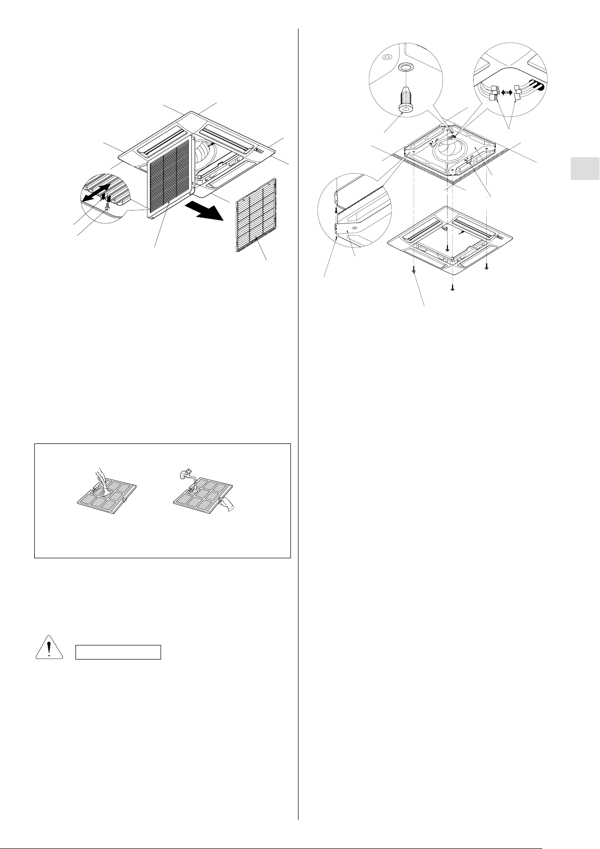
HOW TO REMOVE THE FILTER
HOW TO REMOVE THE CONDENSATE DRAIN PAN
LATCH
SCREW
AIR INTAKE GRILLE
AIR FILTER
1. Remove the screw on each side out of the latch using a
screwdriver.
2. Press on the two latches of the air intake grille with your
thumbs in the direction of the arrow to open the grille.
3. Open the air intake grille downward.
4. Remove the air filter from the air intake grille.
5. Use a vacuum cleaner to remove light dust. If there is
sticky dust on the filter, wash the filter in lukewarm,
soapy water, rinse it in clean water, and dry it.
3. Insert the filter correctly again inside the grille, close the
grille letting the latches slide toward the outside and fix
again the latch with the screw on both sides.
FILTER CLEANING
Use a vacuum cleaner to remove light dust. If there is
sticky dust on the filter, wash the filter in lukewarm,
soapy water, rinse it in clean water, and dry it.
RUBBER CORK
SUPPORT
PLATE (2)
SCREW (4)
SPECIAL SCREW (4)
1. Open the air intake grille.
2. Drain the condensate water into a bucket trough the
rubber cork that should be soon closed.
3. Remove the frame-grille assembly by loosening the four
special screws with washer; you can utilise the two clips
that fix the frame to the unit.
4. Disconnect the electrical connectors between the framegrille assembly and the unit.
5. Remove the four screws of the two support plates.
6. Grasp the two support plates, remove with care the
condensate drain pan and clean it inside, if necessary.
7. Once finished the maintenance, reassemble the pan,
aligning the side with the hole for condensate drain and
the side with the pump; insert the connectors of the unit
into the proper hole in the pan.
8.Fix again the four screws of the support plates and the
frame group aligning the corner from which the wires exit
and the corner with the connectors of the unit.
9.Mount the air intake grille along with the filter; be sure
that the safety string has been attached and that the
latch screw has been fixed on both sides.
CONNECTORS
CONDENSATE
DRAIN PAN
CLIPS (2)
GB
ADDITIONAL MAINTENANCE
The inspection or replacement of internal components
involve the removal of the condensate drain pan.
CAUTION
Some metal edges and the vanes of heat exchanger are
sharp and may cause injury if handled improperly; be
especially careful when you clean these parts.
WATER LEVEL ALARM
• Note: During normal operation, the condensate
pump is actuated at the same time as the main
exchanger valve.
• In case of abnormal backflow of water into the
condensate tank due to a faulty pump, a dirty
tank, or a plugged drain line,...), a safety contact
(floater) disconnects the remote control’s power
supply and causes the ventilation to shut down,
the control valve to close and activates the pump
on a permanent basis. In case of models with
remote control unit the operation lamp is blinking.
10
Page 11

TIPS FOR ENERGY SAVING
DO NOT:
l
Block the air intake and outlet of the unit.
If they are obstructed, the unit will not work well, and
may be damaged.
l
Let direct sunlight into the room. Use sunshades,
blind or curtain.
DO:
l
Always try to keep the air filter clean. A clogged filter
will impair the performance of the unit.
l
To prevent conditioned air from escaping, keep
windows, doors and any other openings closed.
l
The room temperature is above 10°C for cooling and
dehumidification mode.
TROUBLESHOOTING
WARNING
• The use of portable telephones near the air conditioner
may cause disturbance to its normal operation and must
be avoided. In case abnormal operation is noticed,
(OPR operation lamp lights (4) but the air conditioner
will not run) to restore normal operation turn-off electric
supply for 60 seconds at least, by disconnecting the
main switch or the wall plug, then start again the air
conditioner.
• If your air conditioner does not work properly, first check
the following points before requesting service.
If it still does not work properly, contact your dealer or
service centre.
Trouble: the terminal does not run at all.
Possible cause:
1. Power failure.
2. Leakage breaker tripped.
3. Line voltage is too low.
4. Operation button is OFF.
5. Batteries in remote control unit have run down.
Remedy:
1. Restore power.
2. Contact service centre.
3. Consult your electrician or dealer.
4. Press the button again.
5. Replace batteries.
Trouble: Poor cooling or heating performance.
Possible cause:
1. Dirty or clogged air filters.
2. Heat source or many people in room.
3. Doors and/or windows are open.
4. Obstacle near air intake or air discharge port.
5. The set temperature on the remote control unit is too
high.
Remedy:
1. Clean air filters to improve airflow.
2. Eliminate heat source if possible.
3. Shut them to keep the heat or cold out.
4. Remove it to ensure good airflow.
5. Set the right temperature on the remote control unit.
Trouble: Clicking sound is heard from the terminal.
Possible cause:
1. In heating or cooling operation, any plastic parts may
expand or shrink due to a sudden temperature change.
In this event, a clicking sound may occur.
Remedy:
1. This is normal, and the sound will disappear when an
even temperature is settled.
11GB12
Page 12

LEDS’ TABLE
LEGEND
= LED ON
= LED OFF
= flashing LED (0,1 second ON, 0,1 second OFF)
= flashing LED (2 seconds ON, 2 seconds OFF)
= flashing LED (7 seconds ON, 7 seconds OFF)
NORMAL OPERATION
LD1
STANDBY
Red
● ● ○
○ ● ○
○ ● ●
● ● ●
● ○ ○
OTHER COMBINATIONS See DIAGNOSTICS
DIAGNOSTICS
Damaged air sensor
Damaged coil sensor
Set temperature can not be reached
Wrong operating mode
Communication error (only for SLAVE on SACBUS)
Condensate level alarm
LD2
STANDBY
Green
Error
LD3
TIMER
Blue
Unit in heating mode waiting to warm (ICT < 32°C)
Unit in heating mode and thermo-off
Unit in heating mode with heat exchanger already hot (ICT > 32°C)
Unit in cooling mode
Unit in heating mode with heat exchanger already hot and active timer
Unit in cooling mode and active timer
Unit in heating mode, in thermo-off anche active timer
Unit off
LD1 (Stby) LD2 (Opr) LD3 (Timer)
○
LED’s status
○ ○
LIGHTS UP CONDITIONS
○
○
The system stops and the condensate
GB
Effects
The system stops
pump is activated
NOTES
• “Damaged sensor” means a situation in which the sensor is disconnected or short-circuited.
• The condensate level alarm is active only in cooling (COOL) and dehumidifying (DRY) mode.
• “Wrong operating mode” indicates that it is selected by remote control an operating mode not permitted by the system
conguration set during installation (for example, you select the heating mode, but the unit is set to “cooling only”).
• “Set temperature can not be reached” indicates that:
• the unit is in cooling mode, but the water temperature is above the set temperature for more than 10 minutes, so the
desired temperature can not be reached
or:
• the unit is in heating mode, but the water temperature is lower than the set temperature for more than 10 minutes,
so the desired temperature can not be reached.
• “Communication Error” indicates that the unit is set as SLAVE on SACBUS protocol, but which has lost communication
with the MASTER board for more than 30 seconds.
Page 13

Technibel is a trademark of NIBE ENERGY SYSTEM FRANCE
Z.I. Route départementale 28
01600 Reyrieux France
Tél. 33 4 74 00 92 92 - Fax 33 4 74 00 42 00
 Loading...