

Technibel CA250X5TAA, CA360X5TAA, GR250X5TAA, GR360X7TAA, GR250X7TAA Technical & Service Manual
...Page 1

TECHNICAL & SERVICE MANUAL
SPLIT SYSTEM AIR CONDITIONER
CA250X5TAA - GR250X5TAA
CA250X5TAA - GR250X7TAA
CA360X5TAA - GR360X7TAA
CA480X5TAA - GR480X7TAA
0.8180.112.1 05/01
Page 2

−
2
−
Table of Contents
1.SPECIFICATIONS…………………………………………………………………………… 3
1-1 Unit Specifications…………………………………………………………………….. 3
1-2 Major Component Specifications……………………………………………………. 7
(A) Indoor Unit……………………………………………………………………….... 7
(B) Outdoor Unit………………………………………………………………………. 9
1-3 Other Component Specifications……………………………………………………. 12
(A) Indoor Unit……………………………………………………………………….... 12
(B) Outdoor Unit………………………………………………………………………. 13
1-4 Dimensional Data……………………………………………………………………... 14
(A) Indoor Unit……………………………………………………………………….... 14
(B) Outdoor Unit………………………………………………………………………. 16
1-5 Refrigerant Flow Diagram……………………………………………………………. 18
1-6 Operating Range……………………………………………………………………… 20
1-7 Cooling Capacity………………………………………………………………………. 21
1-8 Noise Criterion Curves……………………………………………………………….. 25
1-9 Air Throw Distance Chart…………………………………………………………….. 27
2. PROCESSES AND FUNCTIONS……………………………………………………….… 28
2-1 Room Temperature Control………………………………………………………….. 28
2-2 Freeze Prevention (Cooling)……………………………………………………….… 29
2-3 Drain Pump Control…………………………………………………………………… 29
2-4 Outdoor Fan Control………………………………………………………………….. 30
3. ELECTRICAL DATA………………………………………………………………………... 31
3-1 Electrical Characteristics……………………………………………………………... 31
3-2 Electric Wiring Diagrams / Schematic Diagrams…………………………………... 33
(A) Indoor Unit……………………………………………………………………….... 33
(B) Outdoor Unit………………………………………………………………………. 35
4. SERVICE PROCEDURES………………………………………………………………….. 43
4-1 Troubleshooting……………………………………………………………………….. 43
4-2 A Sensor is Defective…………………………………………………………………. 54
4-3 Operation of Major Electrical parts………………………………………………….. 54
4-4 Checking the Electrical Components……………………………………………….. 55
Page 3

– 3 –
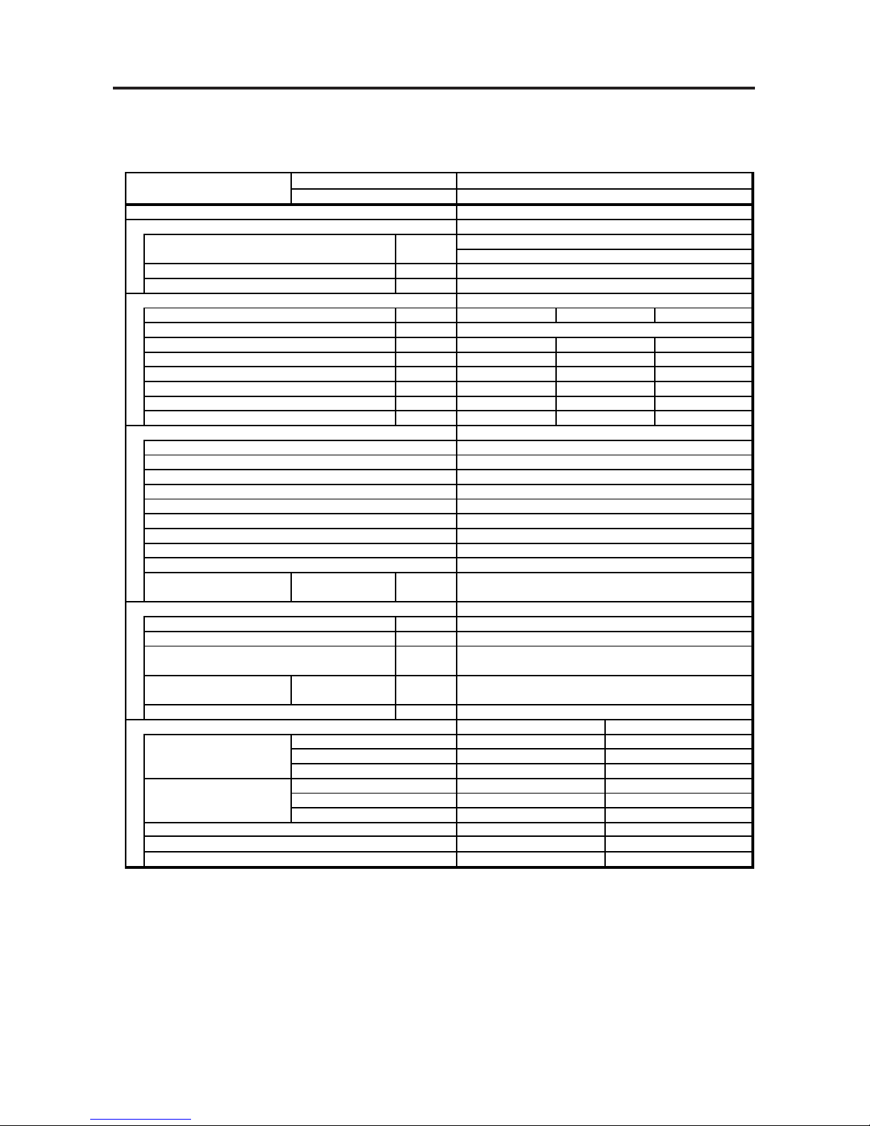
1.SPECIFICATIONS
MODEL No. Indoor Unit CA250X5TAA
Outdoor Unit GR250X5TAA
POWER SOURCE 220 - 230 - 240 V / 1 Phase / 50 Hz
PERFORMANCE Cooling
Capacity kW 7.3
BTU / h 25,000
Air circulation (Hi/Me/Lo) m3 / h 1,140/1,020/840
Moisture removal(High) Liters/ h 3.6
ELECTRICAL RATINGS
Voltage rating V 220 230 240
Available voltage range V 198 - 264
Running amperes* A 14.5 14.6 14.7
Max. running amperes** A 20.2 19.6 19.4
Power input kW 3.01 3.07 3.16
Power factor % 94.4 91.4 89.6
C.O.P W / W 2.43 2.38 2.31
Max. starting amperes A 69 72 75
FEATURES
Controls Microprocessor
Timer ON/OFF 24-hours & Program
Fan speeds Indoor/Outdoor 3 and Automatic control/ 2 (Auto)
Airflow direction (Indoor) Automatic (Remote control)
Air filter Washable, easy access
Remote controller (Accessory) RCS-5PN3E
Refrigerant control Capillary tube
Drain pump (drain connection) Max. head 25cm above drain connection (25A,OD32mm)
Compressor Rotary
Operation sound Indoor - Hi/Me/Lo dB - A 37 / 35 / 31
Outdoor - Hi dB - A 53
REFRIGERANT TUBING
Limit of tubing length m (ft.) 40 (131)
Limit of tubing length at shipment m (ft.) 15 (49)
Limit of elevation difference m (ft.) Outdoor unit is higher than indoor unit: 40 (131)
between the two units Outdoor unit is lower than indoor unit: 25 (82)
Refrigerant tube Narrow tube mm (in) 6.35 (1 / 4)
outer diameter Wide tube mm (in) 15.88 (5 / 8)
Refrigerant amount at shipment kg R22 - 2.4
DIMENSIONS & WEIGHT Indoor unit Outdoor unit
Unit dimensions Height mm (in) 328(12-29/32) 735(28-30/32)
Width mm (in) 860(33-27/32) 940(37)
Depth mm (in) 860(33-27/32) 340(13-12/32)
Package dimensions Height mm (in) 410(16-5/32) 826(32-17/32)
Width mm (in) 988(38-29/32) 1,016(40)
Depth mm (in) 988(38-29/32) 416(16-12/32)
Net weight kg (lb) 30(66) 68(150)
Shipping weight kg (lb) 47(104) 74(163)
Shipping volume m3 (Cu. ft.) 0.4(14.1) 0.349(12.3)
DATA SUBJECT TO CHANGE WITHOUT NOTICE
Cooling :
Rating conditions(*) : Indoor air temperature 27 °C DB / 19 °C WB, Outdoor air temperature 35 °C DB
1-1 Unit Specifications
Page 4

– 4 –
1.SPECIFICATIONS
MODEL No. Indoor Unit CA250X5TAA
Outdoor Unit GR250X7TAA
POWER SOURCE 380 - 400 - 415 V / 3N / 50 Hz
PERFORMANCE Cooling
Capacity kW 7.3
BTU / h 25,000
Air circulation (Hi/Me/Lo) m3 / h 1,140/1,020/840
Moisture removal(High) Liters/ h 3.6
ELECTRICAL RATINGS
Voltage rating V 380 400 415
Available voltage range V 342- 456
Running amperes* A 4.7 4.7 4.6
Max. running amperes** A 6 5.8 5.7
Power input kW 2.76 2.8 2.81
Power factor % 89.2 86 85
C.O.P W / W 2.64 2.61 2.6
Max. starting amperes A 27 29 30
FEATURES
Controls Microprocessor
Timer ON/OFF 24-hours & Program
Fan speeds Indoor/Outdoor 3 and Automatic control/ 2 (Auto)
Airflow direction (Indoor) Automatic (Remote control)
Air filter Washable, easy access
Remote controller (Accessory) RCS-5PN3E
Refrigerant control Capillary tube
Drain pump (drain connection) Max. head 25cm above drain connection (25A,OD32mm)
Compressor Rotary
Operation sound Indoor - Hi/Me/Lo dB - A 37 / 35 / 31
Outdoor - Hi dB - A 53
REFRIGERANT TUBING
Limit of tubing length m (ft.) 40 (131)
Limit of tubing length at shipment m (ft.) 15 (49)
Limit of elevation difference m (ft.) Outdoor unit is higher than indoor unit: 40 (131)
between the two units Outdoor unit is lower than indoor unit: 25 (82)
Refrigerant tube Narrow tube mm (in) 6.35 (1 / 4)
outer diameter Wide tube mm (in) 15.88 (5 / 8)
Refrigerant amount at shipment kg R22 - 2.4
DIMENSIONS & WEIGHT Indoor unit Outdoor unit
Unit dimensions Height mm (in) 328(12-29/32) 735(28-30/32)
Width mm (in) 860(33-27/32) 940(37)
Depth mm (in) 860(33-27/32) 340(13-12/32)
Package dimensions Height mm (in) 410(16-5/32) 826(32-17/32)
Width mm (in) 988(38-29/32) 1,016(40)
Depth mm (in) 988(38-29/32) 416(16-12/32)
Net weight kg (lb) 30(66) 68(150)
Shipping weight kg (lb) 47(104) 74(163)
Shipping volume m3 (Cu. ft.) 0.4(14.1) 0.349(12.3)
DATA SUBJECT TO CHANGE WITHOUT NOTICE
Cooling :
Rating conditions(*) : Indoor air temperature 27 °C DB / 19 °C WB, Outdoor air temperature 35 °C DB
1-1 Unit Specifications
Page 5
– 5 –
1.SPECIFICATIONS
MODEL No. Indoor Unit CA360X5TAA
Outdoor Unit GR360X7TAA
POWER SOURCE 380 - 400 - 415 V / 3N / 50 Hz
PERFORMANCE Cooling
Capacity kW 10.6
BTU / h 36,000
Air circulation (Hi/Me/Lo) m3 / h 1,920/1,680/1,320
Moisture removal(High) Liters/ h 4.7
ELECTRICAL RATINGS
Voltage rating V 380 400 415
Available voltage range V 342 - 456
Running amperes* A 5.2 5.1 5.1
Max. running amperes** A 6.7 6.5 6.4
Power input kW 3.07 3.11 3.15
Power factor % 89.7 88 85.9
C.O.P W / W 3.45 3.41 3.37
Max. starting amperes A 31 33 34
FEATURES
Controls Microprocessor
Timer ON/OFF 24-hours & Program
Fan speeds Indoor/Outdoor 3 and Automatic control/ 2 (Auto)
Airflow direction (Indoor) Automatic (Remote control)
Air filter Washable, easy access
Remote controller (Accessory) RCS-5PN3E
Refrigerant control Capillary tube
Drain pump (drain connection) Max. head 25cm above drain connection (25A,OD32mm)
Compressor Rotary
Operation sound Indoor - Hi/Me/Lo dB - A 43 / 40 / 36
Outdoor - Hi dB - A 54
REFRIGERANT TUBING
Limit of tubing length m (ft.) 50 (164)
Limit of tubing length at shipment m (ft.) 15 (49)
Limit of elevation difference m (ft.) Outdoor unit is higher than indoor unit: 50 (164)
between the two units Outdoor unit is lower than indoor unit: 30 (98)
Refrigerant tube Narrow tube mm (in) 9.52 (3 / 8)
outer diameter Wide tube mm (in) 19.05 (3 / 4)
Refrigerant amount at shipment kg R22 - 4.0
DIMENSIONS & WEIGHT Indoor unit Outdoor unit
Unit dimensions Height mm (in) 358(14-3/32) 1,235(48-20/32)
Width mm (in) 1,150(45-9/32) 940(37)
Depth mm (in) 860(33-27/32) 340(13-12/32)
Package dimensions Height mm (in) 440(17-10/32) 1,326(52-7/32)
Width mm (in) 1,278(50-10/32) 1,016(40)
Depth mm (in) 988(38-29/32) 416(16-12/32)
Net weight kg (lb) 38(84) 94(207)
Shipping weight kg (lb) 62(137) 101(223)
Shipping volume m
3
(Cu. ft.) 0.556(19.6) 0.56(19.8)
DATA SUBJECT TO CHANGE WITHOUT NOTICE
Cooling :
Rating conditions(*) : Indoor air temperature 27 °C DB / 19 °C WB, Outdoor air temperature 35 °C DB
1-1 Unit Specifications
Page 6

– 6 –
1.SPECIFICATIONS
MODEL No. Indoor Unit CA480X5TAA
Outdoor Unit GR480X7TAA
POWER SOURCE 380 - 400 - 415 V / 3N / 50 Hz
PERFORMANCE Cooling
Capacity kW 14
BTU / h 47,800
Air circulation (Hi/Me/Lo) m3 / h 1,920/1,680/1,320
Moisture removal(High) Liters/ h 7.4
ELECTRICAL RATINGS
Voltage rating V 380 400 415
Available voltage range V 342 - 456
Running amperes* A 8.4 8.5 8.9
Max. running amperes** A 10.3 9.9 9.5
Power input kW 4.7 4.76 4.86
Power factor % 85 80.8 76
C.O.P W / W 2.98 2.94 2.88
Max. starting amperes A 71 73 75
FEATURES
Controls Microprocessor
Timer ON/OFF 24-hours & Program
Fan speeds Indoor/Outdoor 3 and Automatic control/ 2 (Auto)
Airflow direction (Indoor) Automatic (Remote control)
Air filter Washable, easy access
Remote controller (Accessory) RCS-5PN3E
Refrigerant control Capillary tube
Drain pump (drain connection) Max. head 25cm above drain connection (25A,OD32mm)
Compressor Rotary
Operation sound Indoor - Hi/Me/Lo dB - A 43 / 40 / 36
Outdoor - Hi dB - A 56
REFRIGERANT TUBING
Limit of tubing length m (ft.) 50 (164)
Limit of tubing length at shipment m (ft.) 15 (49)
Limit of elevation difference m (ft.) Outdoor unit is higher than indoor unit: 50 (164)
between the two units Outdoor unit is lower than indoor unit: 30 (98)
Refrigerant tube Narrow tube mm (in) 9.52 (3 / 8)
outer diameter Wide tube mm (in) 19.05 (3 / 4)
Refrigerant amount at shipment kg R22 - 4.3
DIMENSIONS & WEIGHT Indoor unit Outdoor unit
Unit dimensions Height mm (in) 358(14-3/32) 1,235(48-20/32)
Width mm (in) 1,150(45-9/32) 940(37)
Depth mm (in) 860(33-27/32) 340(13-12/32)
Package dimensions Height mm (in) 440(17-10/32) 1,326(52-7/32)
Width mm (in) 1,278(50-10/32) 1,016(40)
Depth mm (in) 988(38-29/32) 416(16-12/32)
Net weight kg (lb) 38(84) 106(234)
Shipping weight kg (lb) 62(137) 113(249)
Shipping volume m3 (Cu. ft.) 0.556(19.6) 0.56(19.8)
DATA SUBJECT TO CHANGE WITHOUT NOTICE
Cooling :
Rating conditions(*) : Indoor air temperature 27 °C DB / 19 °C WB, Outdoor air temperature 35 °C DB
1-1 Unit Specifications
Page 7

– 7 –
1.SPECIFICATIONS
(A)Indoor Unit
MODEL No. CA250X5TAA
Source 220 - 230 - 240 V / 1 phase / 50 Hz
Remote controller (Accessory) RCS- 5PN3E
Controller P. C. B Ass'y CR - X363GS
Switch Ass'y SW - X363GS
Fan (Number … diameter) mm Turbo (1… ø 490)
Fan motor
Model … Nominal output W SFG6X - 41A5P … 40 W
Source 220 - 230 - 240 V / 1 phase / 50 Hz
No. of pole … r.p.m. (230 V, High) rpm 6 … 470
Coil resistance Ω BRN – WHT :114.0 , ORG–YEL : 66.4
(Ambient temperature 20 °C) WHT–VLT : 23.9 , WHT–PNK : 77.4
VLT –ORG : 12.4 , YEL–BLK : 82.1
Safety device
Operating temperature Open°C130±8 °C
Close°C79±15 °C
Run capacitor VAC , µF 440 V , 4 µF
Heat exchanger
Coil Aluminum plate fin / Copper tube
Rows … fin pitch mm 2 … 1.7
Face area m
2
0.295
Panel
Model No. PNR - X253GS
Indicator Lamp Ass'y IND - X253GS
Dew proof heater 240 V , 26 W
Auto louver motor M2LB24ZA12
Auto louver motor … Rated V, W, rpm. 240 VAC , 3 W , 2.5 rpm
Coil resistance (at 25 °C) Ω 15,620 Ω ± 15 %
1-2 Major Component Specifications
Page 8

– 8 –
1.SPECIFICATIONS
(A) Indoor Unit
MODEL No. CA360X5TAA CA480X5TAA
Source 220 - 230 - 240 V / 1 phase / 50 Hz
Remote controller (Accessory) RCS - 5PN3E
Controller P. C. B Ass'y CR - X363GS
Switch ass'y SW - X363GS
Fan (Number … diameter) mm Turbo (1… ø 490)
Fan motor
Model … Nominal output W SFG6X - 61A3P … 60 W
Source 220 - 230 - 240 V / 1 phase / 50 Hz
No. of pole … r.p.m. (230 V, High) rpm 6 … 530
Coil resistance Ω BRN – WHT : 71.1 , ORG–YEL : 22.7
(Ambient temperature 20 °C) WHT–VLT : 8.7 , VLT –PNK : 43.2
VLT –ORG : 13.3 , YEL–BLK : 54.32
Safety device
Operating temperature Open°C130±8 °C
Close°C79±15 °C
Run capacitor VAC , µF 440 V , 6 µF
Heat exchanger
Coil Aluminum plate fin / Copper tube
Rows … fin pitch mm 2 … 1.7
Face area m
2
0.479
Panel
Model No. PNR - X483GS
Indicator Lamp ass'y IND - X483GS
Dew proof heater 240 V , 31 W
Auto louver motor M2LB24ZA12
Auto louver motor … Rated V, W, rpm 240 VAC , 3 W , 2.5 rpm
Coil resistance (at 25 °C) Ω 15,620 Ω ± 15 %
Page 9

– 9 –
1.SPECIFICATIONS
(B) Outdoor Unit
MODEL No. GR250X5TAA
Source 220 - 230 - 240 V / 1 phase / 50 Hz
Compressor Rotary (Hermetic)
Model ... Code No. C - R221H5V
Nominal output W 2,200
Compressor oil cc 1,350
Coil resistance (at 25°C) Ω
C - R : 0.76, C - S :2.76
Refrigerant amount at shipment kg R22 - 2.4
Safety device Internal/OL - D24
Operating temperature Open °C 160±5/150±10
Close °C 87±9/63±10
Run capacitor V,µF 400V, 40
High pressure switch ACB - 1TB07
Set pressure OFF kg/cm
2
30
ON kg/cm
2
24 ± 2.0
Fan (Number…diameter (mm)) Propeller (1…ø 460)
Fan motor
Model…Nominal output W KFC6S - 91C5P…100 W
No. of pole ... rpm (230V, High) rpm 6...868
Coil resistance Ω BRN – WHT : 61.0
(Ambient temperature 20°C) YEL–PNK : 17.7
WHT–YEL : 64.3
Safety device Internal type
Operating temperature Open °C 130±8
Close °C 79±15
Run capacitor VAC, µF 440 V, 5 µF
Heat exchanger
Coil Aluminium plate fin / Copper tube
Rows ... fin pitch mm 2...2.0
Face area m
2
0.616
+ 2.0
+ 0.5
1-2 Major Component Specifications
Page 10

– 10 –
1.SPECIFICATIONS
(B) Outdoor Unit
MODEL No. GR250X7TAA
Source 380 - 400 - 415 V / 3 phase / 50 Hz
Compressor Rotary (Hermetic)
Model … Code No. C - R224H8S
Nominal output W 2,200
Compressor oil CC 1,350
Coil resistance (at 25°C) Ω R - S:5.54,S - T:5.54,T - R: 5.54
Refrigerant amount at shipment kg R22 - 2.4
Safety device Internal type External type
Overload relay models — FMSA - 1SZ607A
Operating temperature Open °C120±5—
Close °C98±11 —
Operating ampere (at 25°C) A — 6A, 110 %
Run capacitor V, µF—
High pressure switch ACB - 1TB07
Set pressure OFFkg/cm
2
30
ON kg/cm
2
24 ± 2.0
Fan Number … diameter mm Propeller (1 … ø 460)
Fan motor
Model … Nominal output W KFC6S - 91C5P … 100 W
No. of pole … rpm (230 V, High) rpm 6 … 868
Coil resistance Ω BRN – WHT : 61.0 , YEL–PNK : 17.7
(Ambient temperature 20°C)
WHT–YEL : 64.3
Safety device
Operating temperature Open °C130±8
Close °C79±15
Run capacitor VAC, µF 440V, 5 µF
Heat exchanger
Coil Aluminum plate fin / Copper tube
Rows … fin pitch mm 2 … 2.0
Face area m
2
0.616
+ 2.0
+ 0.5
Page 11

– 11 –
1.SPECIFICATIONS
(B) Outdoor Unit
MODEL No. GR360X7TAA GR480X7TAA
Source 380-400- 415 V / 3 phase / 50 Hz
Compressor Rotary (Hermetic) Scroll (Hermetic)
Model...Code No. C - R243H8T ZR61KC - TFD - 522
Nominal output W 2,400 3,750
Compressor oil cc 1,350 2,130
Coil resistance Ω T – R:5.54,R – S:5.54 T1 – T2:2.72,T2 – T3:2.72
(Ambient temperature 25°C ) S – T:5.54 T3 – T1:2.72
Refrigerant amount at shipment kg R 22 - 4.0 R 22 - 4.3
Safety devices Internal type External type Internal type External type
Overload relay models —
FMSA -1SZ607A
—
FMSA -1SZ607A
Operating temperature Open °C 120 ±5— 130—
Close °C 98 ± 11 — 61 —
Operating ampere (at 25°C) A — 6 A, 110 % — 10 A, 110 %
Run capacitor V, µF—
High pressure switch ACB - 1TB07
Set pressure OFF kg/cm
2
30
ON kg/cm
2
24 ± 2.0
Fan (Number...diameter) mm Propeller (2...ø460)
Fan motor
Model...Nominal output W KFC6S - 91C5PX2...100WX2
No. of pole...rpm (230 V, High) rpm 6...871
Coil resistance Ω BRN–WHT : 61.0
(Ambient temperature 20°C) WHT–YEL : 64.3
YEL–PNK : 17.7
Safety device
Operating temperature Open °C130±8
Close °C79±15
Run capacitor VAC, µF 440V,5 µF/440 V,5 µF
Heat exchanger
Coil Aluminum plate fin / Copper tube
Rows...fin pitch mm
2
2...2.0
Face area m
2
1.08
+ 2.0
+ 0.5
Page 12

– 12 –
1
1-3 Other Component Specifications
(A) Indoor Unit
CA250X5TAA CA360X5TAA CA480X5TAA
Power Transformer ATR – I75A
Rated Primary AC 230 V, 50 Hz
Secondary 10.6 V, 0.93 A
Capacity 9.85 VAC
Coil resistance WHT - WHT : 96.5 , BRN - BRN : 0.8 (at 20 °C)
Thermistor cut off temperature °C 150
Thermistor (Coil sensor) PBC - 41E - S26 PBC - 41E - S36
Coil resistance k –10 °C : 23.7 , 5 °C : 12.1
–5 °C : 18.8 , 10 °C : 9.7
0 °C : 15.0 , 15 °C : 8.0
Thermistor (Room or coil sensor) KTEC - 35 - S6
Coil resistance k 0 °C : 16.5 , 40 °C : 2.7
5 °C : 12.8 , 45 °C : 2.2
10 °C : 10.0 , 50 °C : 1.8
20 °C : 6.3 , 55 °C : 1.5
30 °C : 4.0 ,
Drain pump WP20SL - 21
Rated AC 230 V, 14.7 W
Float switch FS - 0218 - 103
Rated (Contact rated) AC 230 V, 50 W
Switch Ass'y SW - X363GS
Indicator Lamp Ass' IND - X253GS
Synchronized Motor M2LB24ZA12
1.SPECIFICATIONS
Page 13

– 13 –
1
(B) Outdoor Unit
MODEL No GR250X7TAA GR360X7TAA GR480X7TAA
Compressor Motor Magnetic Contactor FMSA - 1SZ607A
Coil rated AC 220 - 240 V, 50 Hz
Coil resistance (at 20°C) 828 (at 20 °C)
Contact rated V, A AC 440 V, 13 A
Thermal Relay
Contact rated V, A AC 220 V, 2.25 A
Rated ampere (90 / 120%) A 6 A, 110 % 6 A, 110 % 10 A, 110 %
Auxiliary relay HH62S / 085
Coil rated A AC 240 V, 50 Hz
Coil resistance kW 15.5 ± 20 %
Contact rated A AC 250 V, 10A
Relay RDR - S400
Rated voltage V AC 380 - 415 V, 3 phase, 50 Hz
Resistance (at 20°C) k R - T : 76.3
Thermostat (Coil sensor) YTB - S377
Operating Temperature °C 27.5 ± 1.5 OFF (High)
25.5 ON (Low)
Contact ratedAC 250 V, 1 A
MODEL No GR250X5TAA
Compressor Motor Mgnetic ContactorFMCA - 1SZ607
Coil rated AC 220 - 240 V, 50 Hz
Coil resistance (at 20°C) 828 ± 15 %
Contact rated V, A AC 440 V, 13 A
Auxiliary relay HH62S / 085
Coil rated AC 240 V, 50 Hz
Coil resistance (at 20°C) k 17.2
Contact rated V, A AC 220 V, 5 A
Thermostat (Coil sensor) YTB - S377
Operating Temperature °C 27.5 ± 1.5 OFF (High)
25.5 ON (Low)
Contact rated A AC 250 V, 1 A
+ 1.5
– 0.5
+ 1.5
– 0.5
1.SPECIFICATIONS
Page 14
– 14 –
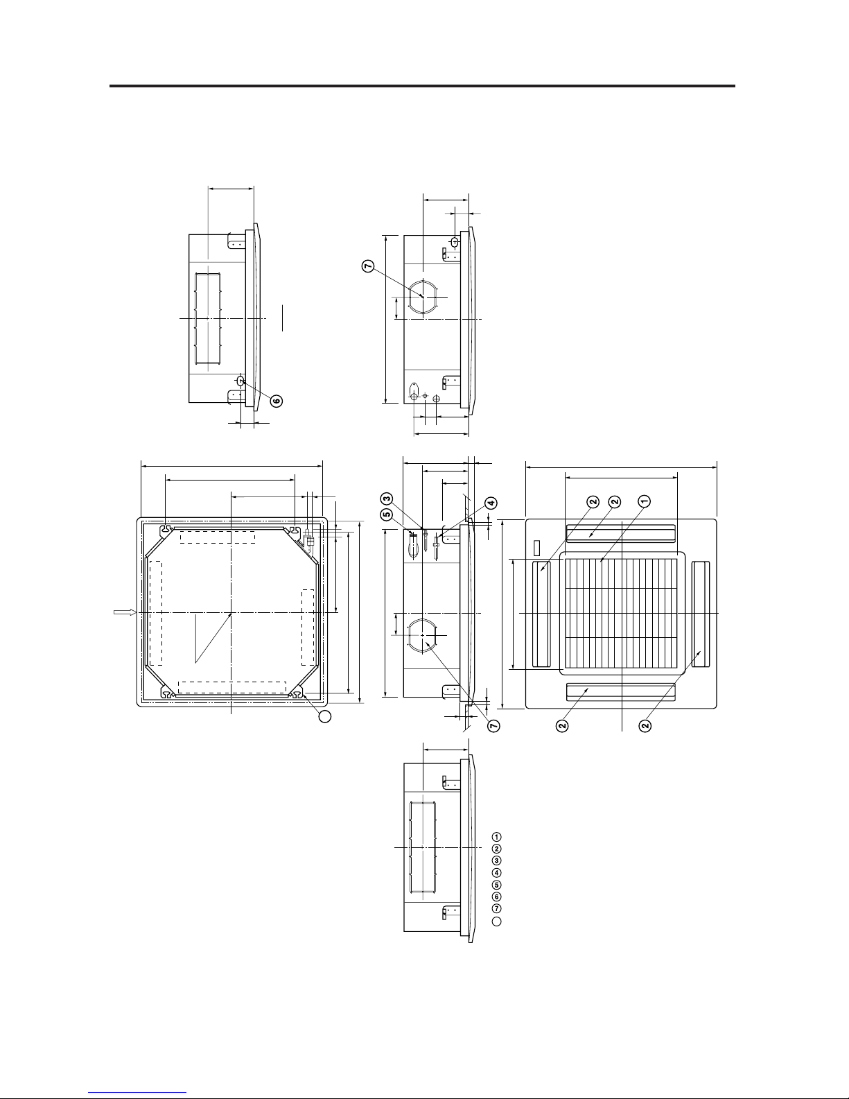
(A)Indoor Unit:CA250X5TAA
860
100
760
500
500
298 30
205
125
12
12
48
860
820 (Ceiling opening)
820 (Ceiling opening)
61
730 (Suspention bolt pitch)
Panel center
590 (Suspention bolt pitch)
345 35
Air intake grille
Air outlet
Refrigerant liquid line (ø 6.35)
Refrigerant gas line (ø 15.88)
Drain connection
Power supply entry
For discharge duct
Suspention bolt mounting
342 15
X-view
0410_X_S
207
100
205
61
760
50 150
255
207
8
8
1.SPECIFICATIONS
1-4Dimensional Data
Page 15

– 15 –
(A)Indoor Unit:CA360X5TAA, CA480X5TAA
1150
1050
790
500
328
30
218
125
860
1110 (Ceiling opening)
820 (Ceiling opening)
61
1020 (Suspention bolt pitch)
Panel center
590 (Suspention bolt pitch)
490 40
Air intake grille
Air outlet
Refrigerant liquid line (ø9.52)
(SPW-X303G56, SPW-X303GS56 ø6.35)
Refrigerant gas line (ø19.05)
(SPW-X303G56, SPW-X303GS56 ø15.88)
Drain connection
Power supply entry
For discharge duct
Suspension bolt mounting
X-view
0603_X_S
218
14535
210
60
760
70 165
285
210
100 100
8
8
342 15
12
48
12
1.SPECIFICATIONS
Page 16

– 16 –
(B) Outdoor Unit :GR250X5TAA
GR250X7TAA
400
380
20
340
20
110660170
735
280
307
940
Dimension : mm
Hole for anchor bolt (4-ø13)
Refrigerant tube joint (narrow tube)
Flare connection 1/4 in (6.35 mm)
Refrigerant tube joint (wide tube)
Flare connection 5/8 in (15.88 mm)
Refrigerant tubing inlet
Power supply inlet
0411_C_S
1.SPECIFICATIONS
1-4Dimensional Data
Page 17

– 17 –
(B) Outdoor Unit :GR360X7TAA
GR480X7TAA
400
380
20
340
20
110660170
1235
580
607
940
Dimension : mm
Hole for anchor bolt (4-ø13)
Refrigerant tube joint (narrow tube)
Flare connection 3/8 in (9.52 mm)
Refrigerant tube joint (wide tube)
Flare connection 3/4 in (19.05 mm)
Refrigerant tubing inlet
Power supply inlet
0412_C_S
1.SPECIFICATIONS
Page 18

– 18 –
Indoor Unit :CA250X5TAA
Outdoor Unit:GR250X5TAA
GR250X7TAA
Indoor Unit :CA360X5TAA Outdoor Unit:GR360X7TAA
O. D.
15.88 mm
(5/8")
Evaporator
Capillary
O. D.
6.35 mm
(1/4")
Condenser
Compressor
Accumulator
Capillary
Sub-condenser
Wide tube
service valve
Narrow tube
service valve
0664_X_S
Strainer
Strainer
HP
High
pressure
switch
O. D.
19.05 mm
(3/4")
Evaporator
Capillary
O. D.
9.52 mm
(3/8")
Condenser
HP
High
pressure
switch
Compressor
Accumulator
Capillary
Sub-condenser
Wide tube
service valve
0605_X_S
Narrow tube
service valve
Strainer
Strainer
1.SPECIFICATIONS
1-5Refrigerant Flow Diagram
Page 19

– 19 –
Indoor Unit :CA480X5TAA
Outdoor Unit:GR480X7TAA
Insulation of Regrigerant Tubing
IMPORTANT
To prevent heat loss and wet floors due to
dripping of condensation, both the wide and
narrow tubes must be well insulated with a
proper insulation material. The thickness of
the insulation should be a min. 8 mm.
After a tube has been
insulated, never try to bend
it into a narrow curve
because it can casue the
tube to break or crack.
Insulator
Thickness:
Min. 8mm
Narrow tube
Wide tube
0133_C_I
O. D.
19.05 mm
(3/4")
Evaporator
Capillary
O. D.
9.52 mm
(3/8")
Condenser
HP
High
pressure
switch
Compressor
Accumulator
Sub-condenser
Wide tube
service valve
0606_X_S
Narrow tube
service valve
Strainer
1.SPECIFICATIONS
Page 20

– 20–
Temperature Indoor air intake temp. Outdoor air intake temp.
Maximum 35°C DB / 22.5°C WB 52°C DB
Minimum 18°C DB / 14°C WB 19°C DB
1.SPECIFICATIONS
1-6Operating Range
Page 21

– 21 –
Indoor Unit :CA250X5TAA Outdoor Unit : GR250X7TAA
TC :Total Cooling Capacity (kW)
SHC:Sensible Heat Capacity (kW)
CI :Compressor Input (kW)
Rating conditions are
:Outdoor Ambient Temp. 35 °C DB
:Indoor Unit Entering Air Temp. 27 °C DB / 19 °C WB
RATING CAPACITY : 7.3 kW AIR FLOW RATE : 1140 m3/h
EVAPORATOR CONDENSER
ENT. TEMP. °C AMBIENT TEMP. C
WB DB 25 30 35 40 45 50
TC 7.37 7.03 6.67 6.26 5.81 5.34
CI 2.32 2.48 2.66 2.92 3.19 3.45
21 SHC 4.9 4.7 4.5 4.3 4.1 3.8
23 SHC 5.4 5.2 5 4.8 4.6 4.4
15 25 SHC 6 5.8 5.6 5.4 5.2 4.9
27 SHC 6.5 6.3 6.2 5.9 5.7 5.34
29 SHC 7.1 6.9 6.67 6.26 5.81 5.34
31 SHC 7.37 7.03 6.67 6.26 5.81 5.34
TC 7.61 7.31 6.96 6.59 6.18 5.75
CI 2.38 2.55 2.74 3 3.27 3.53
21 SHC 4.1 4 3.8 3.7 3.5 3.3
23 SHC 4.7 4.6 4.4 4.2 4 3.8
17 25 SHC 5.3 5.1 4.9 4.8 4.6 4.4
27 SHC 5.8 5.7 5.5 5.3 5.1 4.9
29 SHC 6.4 6.2 6.1 5.9 5.7 5.5
31 SHC 6.9 6.8 6.6 6.4 6.18 5.75
TC 7.88 7.6 #7.3 6.94 6.54 6.1
CI 2.45 2.63 2.82 3.09 3.36 3.63
21 SHC 3.4 3.3 3.2 3 2.8 2.7
23 SHC 4 3.9 3.7 3.6 3.4 3.2
19 25 SHC 4.6 4.4 4.3 4.1 4 3.8
27 SHC 5.1 5 4.9 4.7 4.5 4.3
29 SHC 5.7 5.5 5.4 5.3 5.1 4.9
31 SHC 6.2 6.1 6 5.8 5.6 5.4
TC 8.14 7.85 7.56 7.21 6.86 6.46
CI 2.52 2.7 2.9 3.18 3.45 3.73
23 SHC 3.3 3.2 3 2.9 2.8 2.6
21 25 SHC 3.8 3.7 3.6 3.5 3.3 3.2
27 SHC 4.4 4.3 4.2 4 3.9 3.7
29 SHC 5 4.8 4.7 4.6 4.4 4.3
31 SHC 5.5 5.4 5.3 5.1 5 4.8
TC 8.42 8.17 7.88 7.59 7.24 6.88
CI 2.59 2.77 2.98 3.26 3.54 3.82
23 25 SHC 3.1 3 2.9 2.8 2.7 2.6
27 SHC 3.7 3.6 3.5 3.4 3.2 3.1
29 SHC 4.2 4.2 4 3.9 3.8 3.7
31 SHC 4.8 4.7 4.6 4.5 4.4 4.2
TC 8.76 8.45 8.2 7.91 7.61 7.27
CI 2.67 2.86 3.03 3.34 3.64 3.93
25 27 SHC 3 2.9 2.8 2.7 2.6 2.5
29 SHC 3.6 3.4 3.4 3.3 3.2 3
31 SHC 4.1 4 3.9 3.8 3.7 3.6
1.SPECIFICATIONS
1-7Cooling Capacity
Page 22

– 22 –
Indoor Unit :CA250X5TAA Outdoor Unit : GR250X7TAA
TC :Total Cooling Capacity (kW)
SHC:Sensible Heat Capacity (kW)
CI :Compressor Input (kW)
Rating conditions are
:Outdoor Ambient Temp. 35 °C DB
:Indoor Unit Entering Air Temp. 27 °C DB / 19 °C WB
RATING CAPACITY : 7.3 kW AIR FLOW RATE : 1140 m3/h
EVAPORATOR CONDENSER
ENT. TEMP. °C AMBIENT TEMP. C
WB DB 25 30 35 40 45 50
TC 7.37 7.03 6.67 6.26 5.81 5.34
CI 2.03 2.17 2.33 2.5 2.67 2.84
21 SHC 4.9 4.7 4.5 4.3 4.1 3.8
23 SHC 5.4 5.2 5 4.8 4.6 4.4
15 25 SHC 6 5.8 5.6 5.4 5.2 4.9
27 SHC 6.5 6.3 6.2 5.9 5.7 5.34
29 SHC 7.1 6.9 6.67 6.26 5.81 5.34
31 SHC 7.37 7.03 6.67 6.26 5.81 5.34
TC 7.61 7.31 6.96 6.59 6.18 5.75
CI 2.08 2.23 2.4 2.57 2.74 2.91
21 SHC 4.1 4 3.8 3.7 3.5 3.3
23 SHC 4.7 4.6 4.4 4.2 4 3.8
17 25 SHC 5.3 5.1 4.9 4.8 4.6 4.4
27 SHC 5.8 5.7 5.5 5.3 5.1 4.9
29 SHC 6.4 6.2 6.1 5.9 5.7 5.5
31 SHC 6.9 6.8 6.6 6.4 6.18 5.75
TC 7.88 7.6 #7.3 6.94 6.54 6.1
CI 2.15 2.3 2.47 2.65 2.82 3
21 SHC 3.4 3.3 3.2 3 2.8 2.7
23 SHC 4 3.9 3.7 3.6 3.4 3.2
19 25 SHC 4.6 4.4 4.3 4.1 4 3.8
27 SHC 5.1 5 4.9 4.7 4.5 4.3
29 SHC 5.7 5.5 5.4 5.3 5.1 4.9
31 SHC 6.2 6.1 6 5.8 5.6 5.4
TC 8.14 7.85 7.56 7.21 6.86 6.46
CI 2.21 2.37 2.54 2.72 2.9 3.08
23 SHC 3.3 3.2 3 2.9 2.8 2.6
21 25 SHC 3.8 3.7 3.6 3.5 3.3 3.2
27 SHC 4.4 4.3 4.2 4 3.9 3.7
29 SHC 5 4.8 4.7 4.6 4.4 4.3
31 SHC 5.5 5.4 5.3 5.1 5 4.8
TC 8.42 8.17 7.88 7.59 7.24 6.88
CI 2.27 2.43 2.61 2.79 2.98 3.16
23 25 SHC 3.1 3 2.9 2.8 2.7 2.6
27 SHC 3.7 3.6 3.5 3.4 3.2 3.1
29 SHC 4.2 4.2 4 3.9 3.8 3.7
31 SHC 4.8 4.7 4.6 4.5 4.4 4.2
TC 8.76 8.45 8.2 7.91 7.61 7.27
CI 2.34 2.51 2.66 2.86 3.07 3.26
25 27 SHC 3 2.9 2.8 2.7 2.6 2.5
29 SHC 3.6 3.4 3.4 3.3 3.2 3
31 SHC 4.1 4 3.9 3.8 3.7 3.6
1.SPECIFICATIONS
Page 23

– 23 –
Indoor Unit :CA360X5TAA Outdoor Unit : GR360X7TAA
TC :Total Cooling Capacity (kW)
SHC:Sensible Heat Capacity (kW)
CI :Compressor Input (kW)
Rating conditions are
:Outdoor Ambient Temp. 35 °C DB
:Indoor Unit Entering Air Temp. 27 °C DB / 19 °C WB
RATING CAPACITY : 10.6 kW AIR FLOW RATE : 1920 m3/h
EVAPORATOR CONDENSER
ENT. TEMP. °C AMBIENT TEMP. C
WB DB 25 30 35 40 45 50
TC 10.7 10.21 9.69 9.08 8.44 7.76
CI 2.11 2.25 2.42 2.63 2.86 3.07
21 SHC 7.3 7 6.8 6.5 6.2 5.9
23 SHC 8.2 8 7.7 7.4 7.1 6.8
15 25 SHC 9.1 8.9 8.6 8.3 8 7.7
27 SHC 10.1 9.8 9.6 9.08 8.44 7.76
29 SHC 10.7 10.21 9.69 9.08 8.44 7.76
31 SHC 10.7 10.21 9.69 9.08 8.44 7.76
TC 11.06 10.61 10.11 9.57 8.98 8.34
CI 2.16 2.31 2.48 2.71 2.93 3.15
21 SHC 6.1 5.9 5.7 5.5 5.2 4.9
23 SHC 7.1 6.9 6.6 6.4 6.1 5.8
17 25 SHC 8 7.8 7.6 7.3 7.1 6.8
27 SHC 8.9 8.7 8.5 8.3 8 7.7
29 SHC 9.9 9.7 9.4 9.2 8.9 8.34
31 SHC 10.8 10.6 10.11 9.57 8.98 8.34
TC 11.45 11.03 #10.6 10.07 9.5 8.85
CI 2.23 2.39 2.56 2.79 3.01 3.24
21 SHC 5 4.8 4.6 4.4 4.2 3.9
23 SHC 5.9 5.7 5.6 5.3 5.1 4.8
19 25 SHC 6.9 6.7 6.5 6.3 6 5.8
27 SHC 7.8 7.6 7.4 7.2 7 6.7
29 SHC 8.7 8.5 8.4 8.1 7.9 7.6
31 SHC 9.7 9.5 9.3 9.1 8.8 8.6
TC 11.82 11.41 10.97 10.47 9.96 9.38
CI 2.29 2.45 2.63 2.86 3.1 3.33
23 SHC 4.8 4.6 4.4 4.2 4.1 3.8
21 25 SHC 5.7 5.5 5.4 5.2 5 4.8
27 SHC 6.6 6.5 6.3 6.1 5.9 5.7
29 SHC 7.6 7.4 7.2 7 6.8 6.6
31 SHC 8.5 8.3 8.2 8 7.8 7.6
TC 12.22 11.86 11.45 11.02 10.52 9.99
CI 2.35 2.52 2.7 2.94 3.17 3.41
23 25 SHC 4.6 4.4 4.3 4.1 3.9 3.8
27 SHC 5.5 5.4 5.2 5.1 4.9 4.7
29 SHC 6.4 6.3 6.1 6 5.8 5.6
31 SHC 7.4 7.2 7.1 6.9 6.7 6.6
TC 12.72 12.27 11.9 11.49 11.05 10.56
CI 2.43 2.6 2.75 3.01 3.27 3.51
25 27 SHC 4.4 4.2 4.1 4 3.8 3.7
29 SHC 5.3 5.1 5 4.9 4.7 4.6
31 SHC 6.2 6.1 6 5.8 5.7 5.5
1.SPECIFICATIONS
Page 24

– 24 –
Indoor Unit :CA480X5TAA Outdoor Unit : GR480X7TAA
TC :Total Cooling Capacity (kW)
SHC:Sensible Heat Capacity (kW)
CI :Compressor Input (kW)
Rating conditions are
:Outdoor Ambient Temp. 35 °C DB
:Indoor Unit Entering Air Temp. 27 °C DB / 19 °C WB
RATING CAPACITY : 14 kW AIR FLOW RATE : 1920 m3/h
EVAPORATOR CONDENSER
ENT. TEMP. °C AMBIENT TEMP. C
WB DB 25 30 35 40 45 50
TC 14.13 13.48 12.8 12 11.14 10.25
CI 3.43 3.67 3.94 4.34 4.76 5.17
21 SHC 9.1 8.8 8.4 8 7.5 7
23 SHC 10.1 9.7 9.3 8.9 8.4 8
15 25 SHC 11 10.6 10.2 9.8 9.4 8.9
27 SHC 11.9 11.6 11.2 10.8 10.3 9.8
29 SHC 12.9 12.5 12.1 11.7 11.14 10.25
31 SHC 13.8 13.4 12.8 12 11.14 10.25
TC 14.6 14.01 13.36 12.64 11.86 11.02
CI 3.52 3.77 4.04 4.46 4.88 5.29
21 SHC 7.9 7.6 7.3 6.9 6.5 6.1
23 SHC 8.8 8.5 8.2 7.8 7.5 7.1
17 25 SHC 9.8 9.5 9.1 8.8 8.4 8
27 SHC 10.7 10.4 10.1 9.7 9.3 8.9
29 SHC 11.6 11.3 11 10.6 10.3 9.9
31 SHC 12.6 12.3 11.9 11.6 11.2 10.8
TC 15.12 14.57 #14 13.3 12.54 11.69
CI 3.63 3.89 4.17 4.59 5.02 5.44
21 SHC 6.7 6.4 6.2 5.8 5.5 5.1
23 SHC 7.6 7.4 7.1 6.8 6.4 6
19 25 SHC 8.6 8.3 8 7.7 7.3 7
27 SHC 9.5 9.2 8.9 8.6 8.3 7.9
29 SHC 10.4 10.2 9.9 9.6 9.2 8.8
31 SHC 11.4 11.1 10.8 10.5 10.1 9.8
TC 15.61 15.06 14.49 13.83 13.16 12.39
CI 3.73 3.99 4.29 4.72 5.15 5.58
23 SHC 6.4 6.1 5.9 5.6 5.3 5
21 25 SHC 7.3 7.1 6.8 6.5 6.3 5.9
27 SHC 8.2 8 7.7 7.5 7.2 6.9
29 SHC 9.2 8.9 8.7 8.4 8.1 7.8
31 SHC 10.1 9.9 9.6 9.3 9 8.7
TC 16.14 15.67 15.12 14.56 13.89 13.19
CI 3.83 4.1 4.4 4.84 5.28 5.72
23 25 SHC 6.1 5.9 5.7 5.4 5.2 4.9
27 SHC 7 6.8 6.6 6.4 6.1 5.8
29 SHC 7.9 7.7 7.5 7.3 7 6.8
31 SHC 8.9 8.7 8.5 8.2 8 7.7
TC 16.8 16.21 15.72 15.18 14.59 13.94
CI 3.95 4.23 4.49 4.96 5.43 5.88
25 27 SHC 5.8 5.6 5.4 5.2 5 4.8
29 SHC 6.7 6.5 6.3 6.1 5.9 5.7
31 SHC 7.7 7.4 7.3 7.1 6.9 6.6
1.SPECIFICATIONS
Page 25

– 25 –
60
50
40
30
20
10
OCTAVE BAND SOUND PRESSURE LEVEL, dB
(0 dB = 0.0002 µbar)
63 125 250 500 1000200040008000
APPROXIMATE
THRESHOLD OF
HEARING FOR
CONTINUOUS
NOISE
BAND CENTER FREQUENCIES, Hz
NC-20
NC-40
NC-50
NC-30
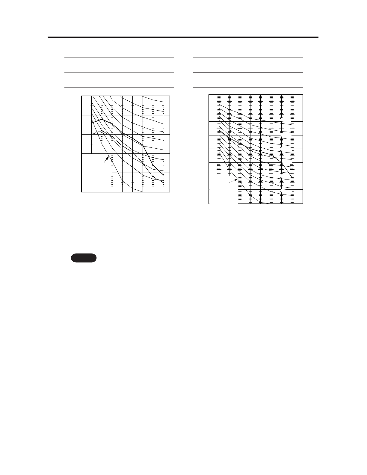
MODEL :GR250X5TAA
:GR250X7TAA
SOUND LEVEL:53dB(A), NC45
CONDITION :Distance1m,Height1m
SOURCE :220 - 230 - 240 V, 1Phase, 50Hz
: 380 - 400 - 415 V, 3Phase, 50Hz
MODEL :CA250X5TAA
SOUND LEVEL:HIGH37dB(A),NC30
LOW 31dB(A),NC22
CONDITION :Distance1 m,Under the unit1.5 m
SOURCE :220 - 230 - 240V,1Phase,50Hz
REMARKS:1.Value obtained in the actual place where the unit is installed may be slightly higher than
the values shown in this graph because of the conditions of operation, the structure of
the building, the background noise and other factors.
2.The test results were obtained from an anechoic room.
NOTE To evaluate “Noise level” the maximum number of the measured OCTAVE BAND
SOUND PRESSURE LEVEL is used. Read the number on each BAND CENTER
FREQUENCIES (horizontal axis) ranging from 63Hz to 8000Hz and select the maximum
value (vertical axis) among them.
90
80
70
60
50
40
30
20
10
60 125
250
500
100020004000
8000
APPROXIMATE
THRESHOLD OF
CONTINUOUS
NOISE
NC-70
NC-50
NC-60
NC-40
NC-30
NC-20
OCTAVE BAND SOUND PRESSURE LEVEL, dB
(0dB=0.0002 µbar)
BAND CENTER FREQUENCIES, Hz
60
50
40
30
20
10
OCTAVE BAND SOUND PRESSURE LEVEL, dB
(0dB=0.0002 µbar)
63 125 250 500 1000200040008000
APPROXIMATE
THRESHOLD OF
HEARING FOR
CONTINUOUS
NOISE
BAND CENTER FREQUENCIES, Hz
NC-20
NC-40
NC-50
NC-30
MODEL :CA360X5TAA
SOUND LEVEL:HIGH43dB(A),NC36
LOW 36dB(A), NC24
CONDITION :Distance1 m,Under the unit1.5 m
SOURCE :220 - 230 - 240V,1Phase,50Hz
90
80
70
60
50
40
30
20
10
60 125
250
500
100020004000
8000
APPROXIMATE
THRESHOLD OF
CONTINUOUS
NOISE
NC-70
NC-50
NC-60
NC-40
NC-30
NC-20
OCTAVE BAND SOUND PRESSURE LEVEL, dB
(0dB=0.0002 µbar)
BAND CENTER FREQUENCIES, Hz
MODEL : GR360X7TAA
SOUND LEVEL:54dB(A), NC45
CONDITION :Distance1 m,Height1 m
SOURCE : 380 - 400 - 415 V, 3Phase, 50Hz
1.SPECIFICATIONS
1-8Noise Criterion Curves
Page 26
– 26 –
REMARKS:1.Value obtained in the actual place where the unit is installed may be slightly higher than
the values shown in this graph because of the conditions of operation, the structure of
the building, the background noise and other factors.
2.The test results were obtained from an anechoic room.
NOTE To evaluate “Noise level” the maximum number of the measured OCTAVE BAND
SOUND PRESSURE LEVEL is used. Read the number on each BAND CENTER
FREQUENCIES (horizontal axis) ranging from 63Hz to 8000Hz and select the maximum
value (vertical axis) among them.
MODEL :CA480X5TAA
SOUND LEVEL:HIGH43dB(A),NC36
LOW 36dB(A),NC24
CONDITION :Distance1m,Under the unit1.5 m
SOURCE :220 - 230 - 240V,1Phase, 50Hz
MODEL :GR480X7TAA
SOUND LEVEL:56dB(A), NC47
CONDITION :Distance1 m,Height1 m
SOURCE :380 - 400 - 415 V,3Phase, 50Hz
60
50
40
30
20
10
OCTAVE BAND SOUND PRESSURE LEVEL, dB
(0dB=0.0002 µbar)
63 125 250 500 1000200040008000
APPROXIMATE
THRESHOLD OF
HEARING FOR
CONTINUOUS
NOISE
BAND CENTER FREQUENCIES, Hz
NC-20
NC-40
NC-50
NC-30
90
80
70
60
50
40
30
20
10
63 125 250 500 1000200040008000
BAND CENTER FREQUENCIES, Hz
APPROXIMATE
THRESHOLD OF
HEARING FOR
CONTINUOUS
NOISE
NC-70
NC-50
NC-20
NC-60
NC-40
NC-30
OCTAVE BAND SOUND PRESSURE LEVEL, dB
(0dB=0.0002 µbar)
1.SPECIFICATIONS
Page 27

– 27 –
MODEL : CA250X5TAA
0123456
0
1
2
3
4
HORIZONTAL DISTANCE (m)
AXIS AIR VELOCITY (m/s)
VERTICAL DISTANCE (m)
AXIS AIR VELOCITY
FAN SPEED
COOLING
ROOM AIR TEMP.
LOUVER ANGLE
HIGH
27˚
30˚
: COOLING
: 0.3 m/s
0659_X_S
MODEL : CA360X5TAA
CA480X5TAA
0123456
0
1
2
3
4
HORIZONTAL DISTANCE (m)
AXIS AIR VELOCITY (m/s)
VERTICAL DISTANCE (m)
AXIS AIR VELOCITY
FAN SPEED
COOLING
ROOM AIR TEMP.
LOUVER ANGLE
HIGH
27˚
30˚
: COOLING
: 0.3 m/s
0661_X_S
1.SPECIFICATIONS
1-9 Air Throw Distance Chart
Page 28
– 28 –
2
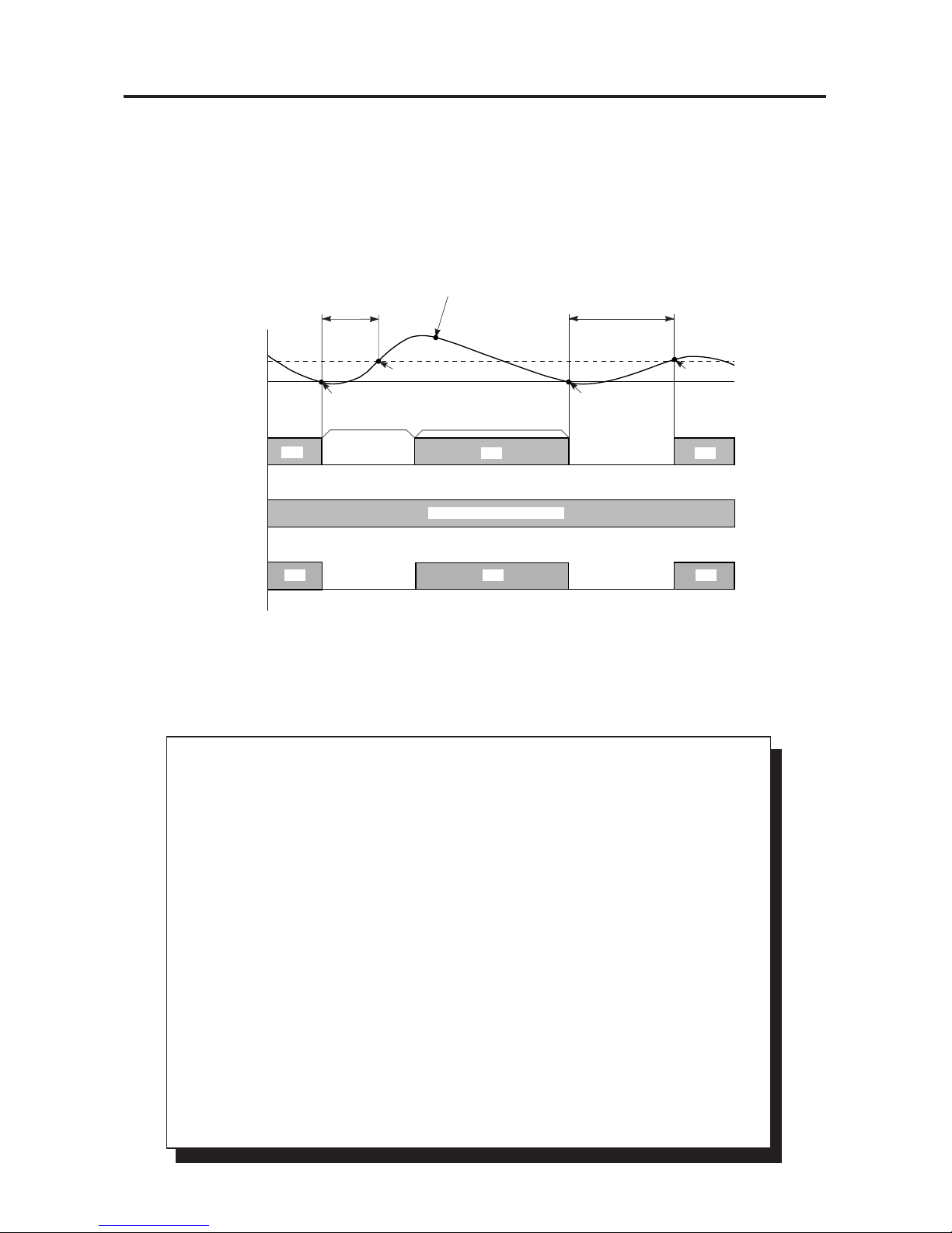
2-1 Room T emperature Control
The Unit adjusts room temperature by turning the outdoor unit’s compressor ON and OFF.
This process is controlled by the thermostat located in the remote control unit.
The figures on this and the next pages show how each part of the system performs when
the room temperature changes and the thermostat activates the compressor to start
(thermo ON) or stop (thermo OFF). Fig. 6 shows about the cooling cycle.
Fig. 6
THERMO ON
ROOM TEMPERATURE
THERMO ON
S. T.+0.5°C
SET TEMP. T°C
(S.T.)
COMPRESSOR
OFF
OFF
WITHIN 3 MINUTE
MORE THAN
5 MINUTES
ON
ON ON
0607_X_S
OFF OFF
INDOOR FAN
OUTDOOR FAN
SET SPEED (MANUAL)
THERMO OFF
3 MINUTES
THERMO OFF
MORE THAN 3 MINUTES
ON ON
ON
Chart Summary and Explanations
❑ Once the compressor starts, it keeps running for 5 minutes.
❑ Once the compressor stops, it will not start running again for 3 minutes.
❑ If you change the operation mode during the cooling cycle, the control circuit stops the
compressor for 3 minutes.
❑ For 5 minutes after the compressor is first turned on, and for 3 minutes after it is turned off,
the compressor is not controlled by the room sensor.
❑ Thermo ON: When room temperature rises 0.5°C above the set temperature T˚,
(T˚+0.5 °C):
Compressor ➞ ON
❑ Thermo OFF: When the room temperature is equal to or below the set temperature T˚:
Compressor ➞ OFF
❑ In case of wireless remote control model (GS type).
• The remote control unit sends the temperature signal to the air conditioner regularly at 3
minute intervals. If the signal from the remote control unit stops for more than 10 minutes
due to the damage of the remote control unit or other trouble, the air conditioner will
switch to the temperature sensor which is built in the indoor unit and control the room
temperature. In these cases, the temperature around the remote contorl unit may differ
from the temperature detected at the air conditioner’s position.
• If the remote control is located near a heat source, such as a space heater or in direct
sunlight, press the A/C SENSOR button to switch to the sensor in the indoor unit.
2.PROCESSES AND FUNCTIONS
Page 29

– 29 –
2
2-2 Freeze Prevention
Freeze Prevention keeps the indoor heat exchange coil from freezing. Freezing reduces
the efficiency of the unit, and frost buildup on the coil blocks cool air circulation from the
indoor unit’s fan.
Fig. 7
2-3 Drain Pump Control
Drain pump operates when compressor starts to operate or when Float Switch turns off.
COMPRESSOR
OUTDOOR FAN
INDOOR FAN
OFF
OFF OFF
OFF
INDOOR COIL
TEMPERATURE
MORE THAN 10 MINUTES
FREEZE
PREVENTION
6 MINUTES 10 MINUTES
FREEZE
PREVENTION
6 MINUTES
(THERMO OFF)
(THERMO ON)
–1°C
ON
ON
ON
ON
ON
ON
0608_X_S
SET SPEED
Fig. 8
ON
ON
ON
ON
ON
ON
ON
ON
ON
ON
SET SPEED
OFF
OFF
OFF
OFF
OFF
OFF
FLOAT SWITCH
ON: low water level
OFF: high water level
COMPRESSOR
DRAIN PUMP
OUTDOOR FAN
INDOOR FAN
20 MINUTES
0609_X_S
2.PROCESSES AND FUNCTIONS
Page 30

– 30 –
2
2-4 Outdoor Fan Control
• In low outdoor temperature, the outdoor fan is set automatically from HIGH to LOW to
prevent the indoor heat exchanger from freezing.
• When the outdoor temperature falls below 25.5°C, the outdoor fan is set from HIGH to
LOW automatically. When the outdoor temperature rises to 27.5°C, the outdoor fan is
set from LOW to HIGH automatically.
2.PROCESSES AND FUNCTIONS
Page 31

– 31 –
3.ELECTRICAL DATA
Indoor Unit Outdoor Unit
Complete Unit
Fan Motor Fan Motor Compressor
Performance at 220 - 240 V / 1 phase / 50 Hz 220 - 240 V / 1 phase / 50 Hz
Rating conditions
A 0.60 / 0.63 0.75 / 0.78 13.32 / 13.74 14.67 / 15.15
kW 0.13 / 0.15 0.17 / 0.19 2.76 / 2.82 3.06/ 3.16
Full load conditions
A 0.60 / 0.63 0.75 / 0.78 18.87/18.03 20.22 / 19.44
kW 0.13 / 0.15 0.17 / 0.19 3.92/ 3.93 4.22 / 4.27
Starting amperes A 1 / 1 1 / 1 67 / 73 69 / 75
Rating Conditions :Indoor Air Temperature 27 °C DB / 19 °C WB
Outdoor Air Temperature35 °C DB
Full Load Conditions:Indoor Air Temperature 35 °C DB / 22.5 °C WB
Outdoor Air Temperature52 °C DB
Indoor model : CA250X5TAA /Outdoor model : GR250X5TAA
Indoor model : CA250X5TAA /Outdoor model : GR250X7TAA
Indoor Unit Outdoor Unit
Complete Unit
Fan Motor Fan Motor Compressor
Performance at 220 - 240 V / 1 phase / 50 Hz 380 - 415 V / 3 phase / 50 Hz
Rating conditions
A 0.60 / 0.63 0.75 / 0.78 4.32 / 4.20 4.74 / 4.62
kW 0.13 / 0.15 0.17 / 0.19 2.46 / 2.47 2.76/ 2.81
Full load conditions
A 0.60 / 0.63 0.75 / 0.78 5.52/5.22 5.95 / 5.65
kW 0.13 / 0.15 0.17 / 0.19 3.27/ 3.26 3.56 / 3.59
Starting amperes A 1 / 1 1 / 1 25 / 28 27 / 30
Indoor model : CA360X5TAA /Outdoor model : GR360X7TAA
Indoor Unit Outdoor Unit
Complete Unit
Fan Motor Fan Motor Compressor
Performance at 220 - 240 V / 1 phase / 50 Hz 380 - 415 V / 3 phase / 50 Hz
Rating conditions
A 0.92 / 0.93 1.51 / 1.56 4.46 / 4.37 5.21 / 5.11
kW 0.20 / 0.22 0.33 / 0.37 2.54 / 2.56 3.07 / 3.15
Full load conditions
A 0.92 / 0.93 1.51 / 1.56 5.96 / 5.64 6.72 / 6.41
kW 0.20 / 0.22 0.33 / 0.37 3.53 / 3.51 4.06 / 4.10
Starting amperes A 2 / 2 3 / 3 27 / 30 31 / 34
3-1 Electrical characteristics
Page 32

– 32 –
3.ELECTRICAL DATA
Indoor model : CA480X5TAA /Outdoor model : GR480X7TAA
Indoor Unit Outdoor Unit
Complete Unit
Fan Motor Fan Motor Compressor
Performance at 220 - 240 V / 1 phase / 50 Hz 380 - 415 V / 3 phase / 50 Hz
Rating conditions
A 0.92 / 0.93 1.51 / 1.56 7.66 / 8.19 8.37 / 8.86
kW 0.20 / 0.22 0.33 / 0.37 4.17 / 4.27 4.70 / 4.86
Full load conditions
A 0.92 / 0.93 1.51 / 1.56 10.18 / 10.07 10.93 / 10.81
kW 0.20 / 0.22 0.33 / 0.37 5.87 / 5.88 6.40 / 6.48
Starting amperes A 2 / 2 3 / 3 66 / 70 71 / 75
Rating Conditions :Indoor Air Temperature 27 °C DB / 19 °C WB
Outdoor Air Temperature35 °C DB
Full Load Conditions:Indoor Air Temperature 35 °C DB / 22.5 °C WB
Outdoor Air Temperature52 °C DB
Page 33

– 33 –
TH1 (Coil)
31
DP
DPH
Connector
9P(WHT)
31
FS
21
31
31
31
3175315
213
213
1234
1SP234
123456789
1
P
S
23456789
1
To Outdoor Unit
Power Supply
Terminal Plate(4P)
Connector
4P(WHT)
• Electric Wiring Diagram
2 3 4
GRN/YEL
GRN/YEL
GRN/YEL
GRN/YEL
Earth
Terminal
Earth
Terminal
Earth
Terminal
YEL
ORG
VLT
WHT
GRY
GRY
PNK
BRN
BLK
YEL
WHT
GRY
BLK
BLK
GRY
WHT
YEL
BLK
BLK
FMI
LM
Controller (CR-X363GS)
E
2P(RED)
TH1
TH2 (Room)
21
BLK
BLK
2P(YEL)
TH2 DPH
3P(RED)LM3P(GRN)
21
TR
PS
21
2P(WHT)
PRY
2P(WHT)
SEC
3P(BLU)DP3P(RED)
FS
3P(WHT)
49FMI
FM
COM
5P(WHT)
SUP
BLK
BLK
BLK
BLK
WHT
WHT
RED
WHT
BRN
BRN
BRN
7P(WHT)
MHL
7P(WHT)3P(WHT)
71
71
IND Lamp
Assy
Switch
Assy
RED
ORG
BRN
C
ORG
VLT
WHT
GRY
GRY
PNK
BRN
BRN
(A) Indoor Unit
CA250X5TAA, CA360X5TAA, CA480X5TAA
3.ELECTRICAL DATA
3-2 Electric Wiring Diagrams / Schematic Diagrams
Page 34

– 34 –
• Schematic Diagram
2
1
3
1
3
1
2
IND
3
1
2
717
1
SW
TR
Coil
TH1
2
1
Room
TH2
FS
CR-X363GS
Controller
1
3
5
F
2
1
2
1
3
DP
DPH
RY2
RY1
RY3
RY4
RY5
3
4
LM
1
3
RY3
4P-1
4P-4
1
4P-2
RY5
FMI
C
12
1
735
456
RY1
RY2 RY2
HLM
3
2
1
1
18
3
49FMI
9
RY4
RY4
Symbols Description
FMI
49FMI
C
F
DP
DPH
LM
TR
RY1-RY5
FS
TH1
TH2
Indoor Fan Motor
Indoor Motor Thermal Protector
Capacitor
Fuse
Drain Pump
Dew Proof Heater
Auto Louver Motor
Power Transformer
Auxiliary Relay
Float Switch
Thermistor (Indoor Coil)
Room Thermistor
Symbols Description
CR-X363GS
IND
SW
Indoor Controller
Indicator Lamp Assy
Switch Assy
Terminal Plate
Connector
Terminal
CA250X5TAA, CA360X5TAA, CA480X5TAA
3.ELECTRICAL DATA
Page 35

– 35 –
CM
FM
C1
C2
YEL
WHT
GRY
BRN
PNK
45
452323
1
1
Connector
6P (WHT)
Connector 2P (WHT) 63PH
313213
14
TWSVR
UAB
OLR
PS
Earth
Terminal
C
R
S
GRN/YEL GRN/YEL
GRN/YEL
52C
5
7
8
13
Relay
121
2
6
24
1Y
Power Supply
50Hz 1ø 220 V To Indoor Unit
Terminal
Plate
1
2
4
L
N
WHT
PNK
WHT
PNK
WHT
WHT
RED
BRN
RED
WHT
BLK
WHT
BLU
RED
RED
WHT
• Electric Wiring Diagram
W 854-2-5268-461-00-1 (AE425SCE)
P
S
C
HL
23S
YEL
WHT
GRY
BRN
PNK
RED
RED
(B) Outdoor Unit
GR250X5TAA
3.ELECTRICAL DATA
3-2 Electric Wiring Diagrams / Schematic Diagrams
Page 36

– 36 –
1
2
1Y 52C
4
1
2
N
L
S
V
R
U
1Y
C1
63PH
C2
52C
OLR
23S
FM
CM
LH
C
45
123
W
T
52C
• Schematic Diagram
Symbols Description
CM
FM
52C
63PH
23S
C1, 2
OLR
1Y
Compressor motor
Fan Motor
Compressor Motor Magnetic Contactor
High Pressure Switch
Fan Speedcontrol Thermostat
Capacitor
Overload relay
Auxiliary Relay
Connector
Terminal Plate
GR250X5TAA
3.ELECTRICAL DATA
Page 37

– 37 –
CM
FM
C
YEL
WHT
GRY
BRN
PNK
YEL
WHT
GRY
BRN
PNK
45
45
23
23
1
1
Connector
6P (WHT)
P
S
Connector 2P (WHT) 63PH
313213
14
TWSVR
U
642
A
B
95
9651C
C
PS
HL
23S
49C
Earth
Terminal
R
S
T
GRN/YEL GRN/YEL
GRN/YEL
52C
46
35
8
Relay
S
BATR
C
7
121
2
1Y
47C
Power Supply
50Hz 3ø 380 V / 415 V To Indoor Unit
Terminal
Plate
1
2
4
5
6
7
8
L1
L2
L3
N
PNK
BRN
ORG
WHT
WHT
PNK
PNK
BLU
RED
PNK
YEL
RED
WHT
BLU
ORG
RED
WHT
WHT
BLU
RED
RED
GRY
WHT
ORG
• Electric Wiring Diagram
GR250X7TAA
3.ELECTRICAL DATA
Page 38

– 38 –
1
2
1
AB
S
T
R
C
47C
49C
2
4
52C
1Y
47C
5
6
7
8
L1
L2
L3
N
C
FM
LH
63PH
C
23S
45
123
52C
51C
• Schematic Diagram
Symbols Description
CM
FM
52C
51C
49C
47C
63PH
23S
C
1Y
Compressor motor
Fan Motor
Compressor Motor Magnetic Contactor
Compressor Motor Overcurrent Relay
Compressor Motor Thermal Protector
Negative Phase Relay
High Pressure Switch
Fan Speedcontrol Thermostat
Capacitor
Auxiliary Relay
Connector
Terminal Plate
13
14
5
95
96
51C
52C
1Y
3
CM
GR250X7TAA
3.ELECTRICAL DATA
Page 39

– 39 –
CM
FM1
C1
YEL
WHT
GRY
BRN
PNK
YEL
WHT
GRY
BRN
PNK
45
452323
1
1
Connector
6P (WHT)
Connector 2P (WHT) 63PH
313213
14
TWSVR
U
642
A
B
95
9651C
PS
49C
Earth
Terminal
R
S
T
GRN/YEL GRN/YEL
GRN/YEL
GRN/YEL
52C
46
35
8
Relay
Relay
S
BATR
C
7
121
2
2Y
47C
Power Supply
50Hz 3ø 380 V / 415 V To Indoor Unit
Terminal
Plate
1
2
4
5
6
7
8
L1
L2
L3
N
PNK
BRN
ORG
WHT
WHT
PNK
PNK
BLU
RED
PNK
YEL
RED
WHT
BLU
ORG
GRY
RED
WHT
BLU
RED
RED
GRY
WHT
ORG
ORG
• Electric Wiring Diagram
P
S
FM2
C2
YEL
WHT
GRY
BRN
PNK
YEL
WHT
GRY
BRN
PNK
45
452323
1
1
Connector
6P (WHT)
P
S
3
8
7
14
5
1Y
2
6
C
H
L
23S
WHT
ORG
WHT
VLT
WHT
WHT
GR360X7TAA
3.ELECTRICAL DATA
Page 40

– 40 –
1
2
1
C1
FM1
31
5
54
123
AB
S
T
R
C
47C
49C
H
2
4
52C
1Y
2Y
47C
5
6
7
8
L1
L2
L3
N
C2
FM2
42
L
23S
63PH
C
6
54
123
52C
51C
• Schematic Diagram
Symbols Description
CM
FM1, 2
52C
51C
49C
47C
63PH
23S
C1, 2
1Y, 2Y
Compressor motor
Fan Motor
Compressor Motor Magnetic Contactor
Compressor Motor Overcurrent Relay
Compressor Motor Thermal Protector
Negative Phase Relay
High Pressure Switch
Fan Speedcontrol Thermostat
Capacitor
Auxiliary Relay
Connector
Terminal Plate
13
14
5
95
96
51C
52C
2Y
3
CM
GR360X7TAA
3.ELECTRICAL DATA
Page 41

– 41 –
CM
FM1
C1
YEL
WHT
GRY
BRN
PNK
YEL
WHT
GRY
BRN
PNK
45
452323
1
1
Connector
6P (WHT)
Connector 2P (WHT) 63PH
313213
14
TWSVR
U
642
A
B
95
9651C
PS
Earth
Terminal
T1
T2
T3
GRN/YEL GRN/YEL
GRN/YEL
GRN/YEL
52C
46
35
8
Relay
Relay
S
BATR
C
7
121
2
2Y
47C
Power Supply
50Hz 3ø 380 V / 415 V To Indoor Unit
Terminal
Plate
1
2
4
5
6
7
8
L1
L2
L3
N
PNK
PNK
BRN
ORG
WHT
WHT
PNK
PNK
BLU
RED
PNK
RED
WHT
BLU
GRY
RED
WHT
BLU
RED
RED
GRY
WHT
ORG
ORG
YEL
• Electric Wiring Diagram
P
S
FM2
C2
YEL
WHT
GRY
BRN
PNK
YEL
WHT
GRY
BRN
PNK
45
452323
1
1
Connector
6P (WHT)
P
S
3
8
7
14
5
1Y
2
6
C
H
L
23S
WHT
ORG
WHT
VLT
WHT
WHT
GR480X7TAA
3.ELECTRICAL DATA
Page 42

– 42 –
1
2
1
C1
FM1
31
5
54
123
AB
S
T
R
C
47C
H
2
4
52C
1Y
2Y
47C
5
6
7
8
L1
L2
L3
N
C2
FM2
42
L
23S
63PH
C
6
54
123
52C
51C
• Schematic Diagram
Symbols Description
CM
FM1, 2
52C
51C
47C
63PH
23S
C1, 2
1Y, 2Y
Compressor motor
Fan Motor
Compressor Motor Magnetic Contactor
Compressor Motor Overcurrent Relay
Negative Phase Relay
High Pressure Switch
Fan Speedcontrol Thermostat
Capacitor
Auxiliary Relay
Connector
Terminal Plate
13
14
5
95
96
51C
52C
2Y
3
CM
GR480X7TAA
3.ELECTRICAL DATA
Page 43

– 43 –
4
4-1 Trobleshooting
(1) Check before and after Troubleshooting
Many problems may happen because of wiring or power supply problems, so you should
check these areas first. Problems here can cause false results in some of the other tests,
and so should be corrected first.
11
11
1. Check power supply wiring
(a) Single-phase
❑ Check that power supply wires are correctly connected to terminal No.
1 through No. 4 on the 4P terminal plate in the indoor unit and L and N
on the 6P terminal in the outdoor unit.
(b) 3-phase
❑ Check that power supply wires are correctly connected to terminal No.
1 through No. 4 on the 4P terminal plate in the indoor unit and L1
through L3 and N on the 8P terminal in the outdoor unit.
22
22
2. Check inter-unit wiring
❑ Check that inter-unit control wiring (AC 220 - 240 V Line voltage) is
correctly connected between the indoor unit and outdoor unit.
33
33
3. Check power supply
❑ Check that voltage is within the specified range (±10% of the rating).
❑ Check that power is being supplied.
If the following troubleshooting must be done with power being supplied,
be careful not to thouch any uninsulated live part that can cause
ELECTRIC SHOCK.
44
44
4. Check the lead wires and connectors in indoor and outdoor units.
❑ Check that the sheath of lead wires is not damaged.
❑ Check that the lead wires are firmly connected at the terminal plate.
❑ Check that the wiring is correct.
55
55
5 Reference
• Condition of general cooling operation (Thermo. ON)
SWEEP..................ON
Indoor fan speed....HIGH
Single-phase outdoor unit
3-phase outdoor unit
1
2
4
1
2
4
L
N
Indoor Unit Outdoor Unit
Ground
Ground
B
A
0611_X_S
L
N
Power supply
Inter-Unit
Wiring
(Line voltage)
Fig. 16
1
2
4
1
2
4
L1
N
Indoor Unit Outdoor Unit
Power supply
Inter-Unit
Wiring
(Line voltage)
Ground
Ground
B
A
0612_X_S
L1
L2
L2
L3
L3
N
4.SERVICE PROCEDURES
Page 44

– 44 –
4
(2) Air conditioner does not operate
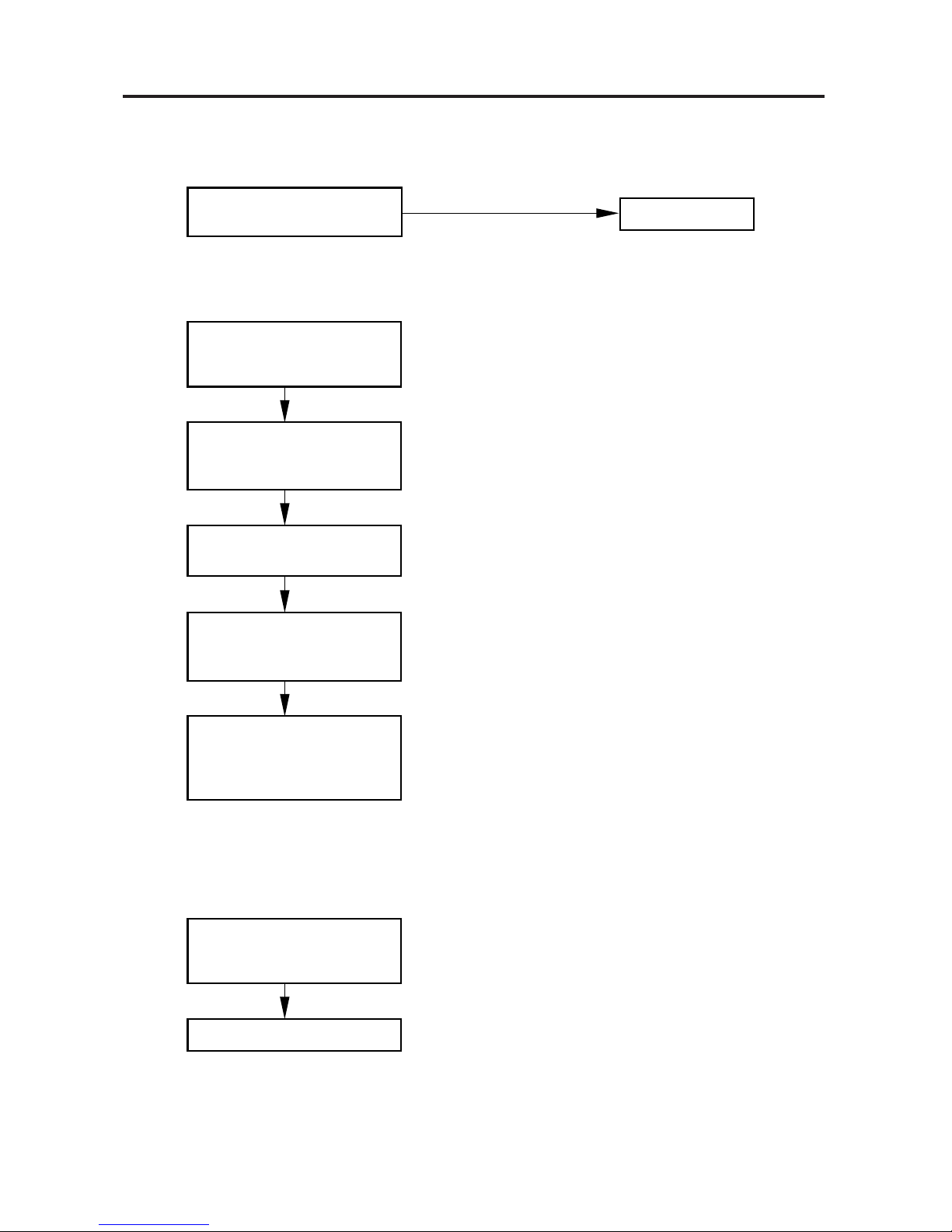
11
11
1 Circuit breaker trips (or fuse blows).
(a) When the circuit breaker is set to ON, it is tripped soon.
• There is a possibility of ground fault.
• Check insulation resistance.
If resistance value is 1MΩ or less, it is a defect of insulation.
1
2
3
(Example)
*Set the circuit breaker to OFF.
Remove power supply cords
from the terminal plate in
the outdoor unit.
• Check insulation resistance
of power supply cords.
OK
NO
NO Insulation of
outdoor unit
is defective.
Execute
rewiring.
Remove interunit power line
from the terminal plate in
the outdoor unit.
• Check insulation resistance
of outdoor unit.
OK
Remove interunit power line
from the terminal plate in
the indoor unit.
• Check insulation resistance
of indoor unit.
OK
Interunit power lines are
defective.
NO
Insulation of
outdoor unit
is defective.
• Check insulation
resistance of
electrical parts
in the outdoor unit.
• Check insulation
resistance of
electrical parts
in the outdoor unit.
Execute
rewiring.
0613_X_S
+
+
+
+
+
+
1
3
2
Circuit
breaker
Outdoor
unit
5 1
6 2
3
4
Indoor
unit
1
2
3
4
Power
supply
cords
Interunit
power line
L
N
Earth
+
+
+
+
+
+
+
+
1
3
2
Circuit
breaker
Indoor
unit
1
2
Power
supply
cords
Interunit
power line
L1
L2
L3
N
Earth
4
+
+
+
+
4
Outdoor
unit
5 1
6
7 2
4
3
84
3
4.SERVICE PROCEDURES
Page 45

– 45 –
4
(b)
Circuit breaker trips in several minutes after turning the air conditioner on.
• There is a possibility of short circuit.
22
22
2 Neither indoor unit nor outdoor unit runs.
A. Power is not supplied
0615_X_S
• Check power supply.
Is power being supplied
to outdoor unit ?
Circuit breaker
is tripped.
Power failure.
Reset the breaker.
Wait for recovery
or consult power
supply company.
NO
B. Check remote control unit.
0616_X_S
• Try to run both indoor and
outdoor units with another
remote control unit.
Refer to item C.
NO
The other remote control
unit is defective.
OK
• Check capacity of circuit
breaker.
NO
• Check resistance of
outdoor fan motor winding.
0614_X_S
Is capacity of circuit
breaker sufficient ?
• Check resistance of
compressor motor winding.
Replace it with a
suitable one.
(= larger capacity)
4.SERVICE PROCEDURES
Page 46

– 46 –
4
C. Check “Operation selector” switch in the indoor unit.
: In case of wireless remote control unit
D. Check compressor motor protectors.
a) High pressure switch (63PH)
b)Compressor motor overcurrent relay (51C)
0618_X_S
• Check high pressure switch.
Does high pressure switch
actuate ? (63PH)
YES
YES
Clean heat exchanger coil
or remove obstacles.
• Is outdoor heat exchanger
coil dirty or are there
obstacles near air suction
inlet of outdoor unit ?
• Check if outdoor fan rotates.
Refer to “Only outdoor fan
does not run.”
NO
Disconnect the socket from 2P (WHT) connector.
Check the continuity between No.1 and No.2 poles
of the socket.
0617_X_S
• Has “Operation selector”
switch been set to ON
position ?
YES
Set “Operation selector”
switch to ON.
NO
But neither unit runs.
Switch Ass’y or P.C.B.
Ass’y in the indoor unit
is defective.
IND. LAMP Ass’y or P.C.B.
Ass’y in the indoor unit
is defective.
0619_X_S
• Check compressor motor
overcurrent relay. (51C)
Does it actuate ?
YES
NO
YES
Consult power supply company
and restore voltage to
normal value.
• Check power supply voltage.
Is voltage 90% or less of
rated voltage ?
• Following causes may be considered.
Locked rotor of compressor.
Overcharged refrigerant.
Air shortage of outdoor unit ventilation.
Obstacles in front of outdoor unit.
NO
Refer to “CHECKING ELECTRICAL COMPONENTS
(Electro magnetic contactor)”.
90% or more of
rated voltage.
4.SERVICE PROCEDURES
Page 47

– 47 –
4
E. Check. auxiliary relay. (1Y or 2Y)
0620_X_S
• Check coil resistance of
auxiliary relay.
(1Y or 2Y)
F. Check indoor fan motor thermal protector (49FMI)
• Disconnect the socket from 9P (WHT) connector.
• Check the continuity
between No. 8 and No.9
poles of the 9P socket.
The thermal protector (49FMI)
is operated.
No continuity.
0621_X_S
• Check fan rotation.
Rotate the fan gently once
or twice by hand.
Check fan casing
for foreign matter
on the inside.
Remove foreign
matter or repair.
Repair or replace.
Fan cannot
be rotated.
OK
• Check fan motor capacitor.
Fan motor burnout
or foreign matter
in bearing.
G. Check fuse on the P.C.B. Ass’y in the indoor unit.
0622_X_S
• Check fuse on the P.C.B.
Ass'y in the indoor unit
for continuity.
• Check transformer. (TR)
• Check resistance of indoor
fan motor winding.
(FMI)
• Check resistance of louver
motor winding. (LM)
When the fuse blows.
OK
OK
OK
• Check resistance of drain
pump winding. (DP)
• Check coil of compressor
motor magnetic contactor.
(52C)
• P.C.B. Ass'y is defective.
OK
OK
OK
• Check resistance of dew
proof heater. (DPH)
4.SERVICE PROCEDURES
Page 48
– 48 –
4
(3) Outdoor unit does not run.
A. Check COOL/FAN selector switch in the remote control unit.
0623_X_S
• Is COOL/FAN selector switch
set to COOL ?
NO
Set to COOL.
B. Check set temperature.
0624_X_S
Try to lower set
temperature by Temperature
setting button “COOLER”.
• Set “Operation selector”
switch to TEST in the
indoor unit.
YES
Outdoor unit runs.
Is room temperature too
low ?
NO
• Try to run both indoor and
outdoor units with another
remote control unit.
OK
The other remote control
unit is defective.
(Room sensor in the remote
control unit is defective.)
C. Outdoor unit is abnormal.
a) Check power supply wiring
0625_X_S
• Check negative phase relay.
(47C)
Dose it operate ?
Rewire power supply cords.
NO
4.SERVICE PROCEDURES
Page 49

– 49 –
4
b) Check compressor motor thermal protector (49C)
0628_X_S
• Check voltage between
terminals No.2 and No.4 at
terminal plate.
• Check P.C.B. Ass’y.
No voltage appears.
P.C.B. Ass’y is defective.
D. Check indoor unit P.C.B.
E. Check float switch.
• Refer to “2-3 Drain Pump Control”
0629_X_S
Is drainage prevented from
flowing ?
• Check drain hose.
YES
• Check float switch (FS).
NO (Wait for 20 minutes.)
0626_X_S
Is temperature of compressor
abnormally high ?
Refrigerant gas shortage.
YES
NO
Compressor is defective.
Charge refrigerant gas.
• Check compressor motor
thermal protector. (49C)
0627_X_S
• Check compressor motor
magnetic contactor.
(52C)
(Only outdoor fan does not run.)
4.SERVICE PROCEDURES
Page 50

– 50 –
4
(4) Indoor unit does not run.
(Indoor fan and louver motor do not run.
0630_X_S
P.C.B. Ass’y is defective.
(5) Some part does not operate.
(1) Indoor fan does not run.
• Check resistance of fan
motor winding.
• Check fan motor capacitor.
OK
Relay RY1 or RY2 on the
P.C.B. Ass’y is defective.
• Check fan rotation.
Rotate the fan gently once
or twice by hand.
0631_X_S
Check fan casing
for foreign matter
on the inside.
Remove foreign
matter or repair.
Repair or replace.
Fan cannot
be rotated.
Fan motor burnout
or foreign matter
in bearing.
OK
(2) Louver motor does not run.
• Check resistance of
louver motor winding.
P.C.B. Ass’y or remote
control unit is defective.
OK
0632_X_S
4.SERVICE PROCEDURES
Page 51

– 51 –
4
(6) Outdoor fan does not run.
• Check resistance of fan
motor winding.
• Check fan motor capacitor
OK
• Check continuity between
terminals on the compressor
motor magnetic contactor.
• Check fan rotation.
Rotate the fan gently once
or twice by hand.
0633_X_S
• Check fan casing
for foreign matter
on the inside.
Remove foreign
matter or repair.
Repair or replace.
Fan cannot
be rotated.
• Fan motor burnout
or foreign matter
in bearing.
GR360X7TAA and GR480X7TAA
(8) Compressor does not run.
• Check compressor motor capacitor.
Refer to
4-4
0635_X_S
• Check resistance of compressor motor winding.
• Check compressor motor overload relay.
(Only SPW-C253G5, SPW-C253G5/M)
OK
OK
OK
NG
NG
NG
Refer to
4-4
Refer to
4-4
Refer to 4-4
NG
Replace magnetic
contactor.
• Check continuity between terminals R-U, and
then S-V on the magnetic contactor.
OK
(7) Outdoor fan speed is not switched from High to Low even when the outdoor
temperature falls below 25.5°C.
• Check the thermostat (23S).
• Check coil resistance of
the auxiliary relay.
(1Y)
0634_X_S
4.SERVICE PROCEDURES
Page 52

– 52 –
4
(9) Poor cooling
Check installation position
of remote control unit.
• Does cool air from air condi tioner reach remote control
unit directly ?
• Is wide tube between indoor unit
and outdoor unit insulated ?
0636_X_S
• Measure temperatures of suction
and discharge air of indoor unit.
Change installation
position of remote
control unit.
Insulate wide tube and
then execute taping with
narrow tube.
YES
NO
Possibility of
refrigerant
shortage.
Charge
refrigerant
(R22).
Temperature
difference
is small.
YES
• Check clogging of air
filter.
Temperature difference between
suction and discharge air is
large enough (Approx. 10 deg. or more).
Clean filter.
Air filter is clogged.
Set fan speed to either
HIGH or MEDIUM.
• Is fan speed set to LOW ?
Reduce cooling load or
replace the unit with
higher cooling capacity.
• Review cooling load estimate,
if performance of air conditioner
is normal.
YES
4.SERVICE PROCEDURES
Page 53

– 53 –
4
(10) Excessive cooling.
• The set temperature is too low.
• Is the remote control unit installed
at a place where it can
detect the room temperature
properly ?
0637_X_S
Set the temperature to
higher value using
temperature setting
button of the remote
control unit.
Change installation
position of the remote
control unit.
YES
NO
4.SERVICE PROCEDURES
Page 54

– 54 –
4
4-2 A Sensor is Defective.
11
11
1 Indoor (heat exchanger) coil temp. Sensor is defective.
(a) Open (=No continuity in sensor)
Compressor and outdoor fan repeat ON for 10 minutes and OFF for 6 minutes
when sensor opens.
(b) Short
“Freeze Prevention” does not operate when dehumidified water is frozen on the
indoor coil.
22
22
2 Room temp. Sensor (in the remote control unit) is defective.
(a) Open (=No continuity in sensor)
Neither outdoor fan nor compressor runs.
(b) Short
Outdoor fan and compressor do not stop. — Excessive cooling.
4-3 Operation of Major Electrical Parts
(Function)
Operation
Indoor unit and Remote Control unit
Oudoor unit
Freeze prevention
Manual
Energy
saver
Night
setback
Timer
(set)
Fan
Operation Mode
Sweep
Stop
Indicator lamps
Thermo. ON VV V V V
Thermo. OFF VV V
Thermo. ON VV V VV V
Thermo. OFF VV V
Thermo. ON VV V VV V
Thermo. OFF VV V
ON Timer V
OFF Timer VVV VV V
VV V
VV
Cool VV* V* VV* V*
Fan VV
Cool VV* V* VV* V*
Fan VV
NOTE V* Refer to Cooling Mode.
Cool
Timer
Sweep
Cool
-ing
Fan
Flap
Night setback
Energy saver
Room
Temp.
Fan Compressor
4.SERVICE PROCEDURES
Page 55

– 55 –
4
4-4 Checking the Electrical Components
(1) Measurement of Insulation
Resistance
• The electrical insulation is acceptable when the
resistance exceeds 1 MΩ.
1 Power Supply Wires
Clamp the earthed wire of the Power Supply wires
with a lead clip of the insulation resistance tester and
measure the resistance by placing a probe on either
of the power wires. (Fig. 42)
Then measure the resistance between the earthed
wire and the other power wires. (Fig. 42)
2 Indoor Unit
Clamp an aluminum plate fin or copper tube with the
lead clip of the insulation resistance tester and
measure the resistance by placing a probe on the
terminal plate (Fig. 43)
3 Outdoor Unit
Measure the resistance by placing a probe on the
terminal plate in the same manner as explained
above 2. (Fig. 43)
4 Measurement of Insulation Resistance for
Electrical parts
• Disconnect the connector of the desired electric
part from terminal plate, P.C.B. Ass’y, etc. (Fig. 44)
• Similarly, disconnect the lead wires from
compressor, capacitor, etc. (Fig. 45)
• Measure the resistance in the same manner as
illustrated on the right.
Refer to Electrical Wiring Diagram.
NOTE
If the probe does not enter the hole because the
hole is too narrow, use a probe with a thinner pin.
Fig. 42
Fig. 43
Fig. 44
Fig. 45
Copper
tube or
metallic part
Clip
Insulation
tester
Probe
Terminal plate
0639_X_S
Copper
tube or
metallic part
Clip
Insulation
tester
Probe
0640_X_S
From fan motor,
compressor and other
parts.
Clip
Probe
Insulation
tester
Metallic
part
0641_X_S
Earthed wire
Clip
Probe
Insulation
tester
0638_X_S
4.SERVICE PROCEDURES
Page 56

– 56 –
4
(2) Checking the Protective Devices
• Disconnect the connector, which consists of P (plug) and S (socket) when you want to
check the protective device.
• Then check continuity among plug’s (and/or socket’s) terminal as in Fig. 46.
• Normality of the protective device can be judged by the following table.
The Protective Device is proved normal if there is a continuity between terminals.
1 Indoor fan motor thermal protector (49FI) . . . . . . Indoor unit
• Disconnect the connector which leads to the indoor fan motor (FMI).
• Check the socket’s terminals.
2 Compressor motor thermal protector (49C) . . . . . . Outdoor unit
• Disconnect both the connectors in the outdoor unit.
• Check terminal between the plug and socket.
3 Outdoor fan motor thermal protector (49FO) . . . . . . Outdoor unit
• Disconnect both the connector which leads to the outdoor fan motor (FMO).
• Check socket’s terminal.
Fig. 46
Ω
socket
Multimeter
0642_X_S
4.SERVICE PROCEDURES
Page 57

– 57 –
4
Fig. 47
Multimeter
Fan motor
Capacitor
0643_X_S
(3) Checking the Electrical Parts
1 Power transformer (TR1) ................. Indoor unit *Measure the coil resistance.
• Primary 220-240 V; Measure the resistance between two WHT lead wire
terminals of socket connected to power transformer.
• Secondary 10.6V ; Measure the resistance between two BRN lead wires.
Refer to “1–3–(A) Other component specifications”.
2 Indoor fan motor (FMI) ............... Indoor unit *Measure the coil resistance.
• Measure the resistance between each terminal of the socket connected to
the indoor fan motor.
Refer to “1–2–(A) Major component specifications”.
3 Outdoor fan motor (FMO) ........... Outdoor unit *Measure the coil resistance.
• Measure the resistance in the same manner as explained above 2.
Refer to “1–2–(B) Major component specifications”.
4 Fan motor capacitor ............ Both in indoor and outdoor unit
• Remove the lead wires from the capacitor terminals,
and then place a probe on the capacitor terminals as
shown in Fig. 47. Observe the deflection of the pointer,
setting the resistance measuring range of the multimeter
to the maximum value.
• The capacitor is “acceptable” if the pointer bounces to a
great extent and then gradually returns to its original
position.
NOTE
The range of deflection and the deflection time differ according to
the capacity of the capacitor.
4.SERVICE PROCEDURES
Page 58

– 58 –
4
5 Fuse on indoor P.C.B. Ass’y
• Remove the P.C.B. Ass’y from the electrical component box. Then pull out the
fuse from the P.C.B. Ass’y. (Fig. 48)
• The check for continuity of the fuse by using the multimeter. (Fig. 49)
Having continuity is acceptable.
(4) Thermistor Characteristic Curve
1 Room temp. sensor 1 Coil sensor
Fuses
Indoor P.C.B. Ass’y
0644_X_S
Fuse
0645_X_S
(PBC-41E)(KTEC-35)
Resistance (kn )
10 15 20 25 30 35 40
10
9
8
7
6
5
4
3
2
1
Temperature (°C)
0374_M_I
–20 –15 –10 –5 0 5 10 15 20
0
5
10
15
20
25
30
35
40
Temperature (°C)
Resistance (kn )
0375_M_I
Fig. 48
Fig. 49
4.SERVICE PROCEDURES
 Loading...