


TEK3-BSW BOX PC PRODUCT MANUAL
(TEK3-BSW)
VER. 1.00
April 15, 2019

TEK3-BSW HARDWARE MANUAL – VER 1.00 APR 15 2019
Page 2 of 37
REVISION HISTORY
Revision
Date
Originator
Notes
1.00
April 15, 2019
TechNexion
First public release

TEK3-BSW HARDWARE MANUAL – VER 1.00 APR 15 2019
Page 3 of 37
TABLE OF CONTENTS
1. Introduction ............................................................................................................................................... 5
1.1. General Care and Maintenance ......................................................................................................... 5
2. TEK3-BSW Product Overview .................................................................................................................. 6
2.1. Functional Block Diagram .................................................................................................................. 6
2.2. Dimensions ......................................................................................................................................... 7
2.3. External Connectors ........................................................................................................................... 8
2.4. Internal Board Connectors ................................................................................................................. 9
2.4.1. Galvanic Isolated (TEK3-xxxxx-Rxx-Lxxx-xxx-xxxx-XG21-xxxx-xxxx) ........................................ 9
2.4.2. Non-Galvanic Isolated (TEK3-xxxxx-Rxx-Lxxx-xxx-xxxx-XS21-xxxx-xxxx) ............................... 10
2.4.3. Board View Without the Power, I/O Expansion and SO-DIMM Modules .................................. 11
3. External Connectors ................................................................................................................................ 12
3.1. USB Host Connectors ...................................................................................................................... 12
3.2. HDMI (High Definition Multi-Media Interface) Connector ................................................................. 12
3.3. miniDP (Mini DisplayPort) Connector ............................................................................................... 12
3.4. USB OTG (Type-C) Connector ........................................................................................................ 13
3.5. Gigabit Ethernet Interface (LAN1/LAN2) .......................................................................................... 13
3.6. Audio Connectors ............................................................................................................................. 14
3.7. Power Input Connector ..................................................................................................................... 14
3.8. PWR Button ...................................................................................................................................... 14
3.9. RST Button ....................................................................................................................................... 14
3.10. Micro-SIM Connector...................................................................................................................... 14
3.11. MicroSD Connector ........................................................................................................................ 15
3.12. LED Light Indicators ....................................................................................................................... 15
3.13. Antenna Holes ................................................................................................................................ 15
3.14. Galvanic Isolated Connectors (TEK3-xxxxx-Rxx-Lxxx-xxx-xxxx-XG21-xxxx-xxxx) (optional) ....... 16
3.14.1. Galvanic Isolated Digital I/O Connectors (GPIO1/GPIO2) (optional) ...................................... 17
3.14.2. Galvanic Isolated Serial Port (RS-XXX) (optional) .................................................................. 18
3.15. Non-Galvanic Isolated Connectors (TEK3-xxxxx-Rxx-Lxxx-xxx-xxxx-XS21-xxxx-xxxx) (optional) 19
3.15.1. Non-Galvanic Isolated Digital I/O Connectors (GPIO1/GPIO2) (optional) .............................. 20
3.15.2. Non-Galvanic Isolated Serial Port (RS-XXX) (optional)........................................................... 21
4. Internal Connectors and Expansion Options .......................................................................................... 22
4.1. CMOS Jumper .................................................................................................................................. 22
4.2. RTC Battery Connector .................................................................................................................... 23
4.3. SO-DIMM DDR3L Slot...................................................................................................................... 23
4.4. M.2 KEY-E Slot ................................................................................................................................. 23
4.5. M.2 KEY-B Slot ................................................................................................................................. 23

TEK3-BSW HARDWARE MANUAL – VER 1.00 APR 15 2019
Page 4 of 37
5. BIOS Setup ............................................................................................................................................. 24
5.1. Entering and Exiting BIOS ................................................................................................................ 24
5.2. BIOS Setup Screens Overview ........................................................................................................ 24
5.2.1. Main ........................................................................................................................................... 25
5.2.2. Chipset ....................................................................................................................................... 26
5.2.3. Advanced ................................................................................................................................... 27
5.2.4. Boot ............................................................................................................................................ 30
5.2.5. Security ...................................................................................................................................... 31
5.2.6. Save & Exit ................................................................................................................................ 32
6. Mounting.................................................................................................................................................. 33
6.1. Surface Mounting ............................................................................................................................. 33
6.2. DIN Mounting .................................................................................................................................... 33
7. Ordering Information ............................................................................................................................... 34
7.1. Custom Part Number Rule ............................................................................................................... 34
7.2. Standard Package Contents ............................................................................................................ 35
8. Important Notice ...................................................................................................................................... 36
9. Disclaimer ............................................................................................................................................... 37

TEK3-BSW HARDWARE MANUAL – VER 1.00 APR 15 2019
Page 5 of 37
1. Introduction
1.1. General Care and Maintenance
Your device is a product of superior design and craftsmanship and should be treated with care.
The following suggestions will help you.
• Keep the device dry. Precipitation, humidity, and all types of liquids or moisture can contain
minerals that will corrode electronic circuits. If your device does get wet, allow it to dry completely.
• Do not use or store the device in dusty or dirty areas. Its parts and electronic components can be
damaged.
• Do not store the device in hot areas. High temperatures can shorten the life of electronic devices,
damage batteries, and warp or melt certain plastics.
• Do not store the device in cold areas. When the device returns to its normal temperature,
moisture can form inside the device and damage electronic circuit boards.
• Do not open the device while power is on. Otherwise electrical shock may result.
• Do not drop, knock, or shake the device. Rough handling can break internal circuit boards and
fine mechanics.
• Do not use harsh chemicals, cleaning solvents, or strong detergents to clean the device.
• Do not paint the device. Paint can clog the parts and prevent proper operation.
• Unauthorized modifications or attachments could damage the device and may violate regulations
governing radio devices.
These suggestions apply equally to your device, battery, charger, or any enhancement. If any device is
not working properly, take it to the nearest authorized service facility for service.
Regulatory information
Disposal of Waste Equipment by Users in Private Household in the European Union
This symbol on the product or on its packaging indicates that this product must not be
disposed of with your other household waste. Instead, it is your responsibility to dispose
of your waste equipment by handing it over to a designated collection point for the
recycling of waste electrical and electronic equipment. The separate collection and
recycling of your waste equipment at the time of disposal will help to conserve natural
resources and ensure that it is recycled in a manner that protects human health and the
environment. For more information about where you can drop off your waste equipment
for recycling, please contact your local city office, your household waste disposal service or the shop
where you purchased the product.
We hereby declare that the product is in compliance with the essential requirements and
other relevant provisions of European Directive 1999/5/EC (radio equipment and
telecommunications terminal equipment Directive).

TEK3-BSW HARDWARE MANUAL – VER 1.00 APR 15 2019
Page 6 of 37
2. TEK3-BSW Product Overview
2.1. Functional Block Diagram

TEK3-BSW HARDWARE MANUAL – VER 1.00 APR 15 2019
Page 7 of 37
2.2. Dimensions
The following figure shows the TEK3-BSW dimensions (unit: mm):

TEK3-BSW HARDWARE MANUAL – VER 1.00 APR 15 2019
Page 8 of 37
2.3. External Connectors
The TEK3-BSW has a number of external connectors.
Front view:
1 3 4 5 6 7 8 9
2
10 11 12 13 14
Rear view:
15 16 17 18 19 20 21 22
23 24 25 26
External Connectors:
No.
Description
No.
Description
1
USB Host connector
14
RS-XXX (Serial Port) connector (optional)
2
USB Host connector
15
Power button
3
HDMI connector
16
Reset button
4
miniDP connector
17
Micro-SIM cardslot
5
USB OTG (Type-C) connector
18
MicroSD cardslot
6
LAN2 RJ45 connector
19
LED Light 1 indicator
7
3.5mm jack Line out
20
LED Light 2 indicator
8
3.5mm jack Line in
21
LED Light 3 indicator
9
3.5mm jack Mic in
22
LED Light 4 indicator
10
Power Input connector
23
Antenna hole
11
LAN1 RJ45 connector
24
Antenna hole
12
GPIO1 connector (optional)
25
Antenna hole
13
GPIO2 connector (optional)
26
Antenna hole

TEK3-BSW HARDWARE MANUAL – VER 1.00 APR 15 2019
Page 9 of 37
2.4. Internal Board Connectors
The TEK3-BSW has several connectors, switches and internal expansion options.
2.4.1. Galvanic Isolated (TEK3-xxxxx-Rxx-Lxxx-xxx-xxxx-XG21-xxxx-xxxx)
Rear view (opened device) with the galvanic isolated I/0 Expansion and Power Expansion modules:
A B C
D
I/O Expansion Module Power Expansion
E Module
No.
Description
No.
Description
A
CMOS jumper
D*
SW1 DIP switch
B
RTC Battery connector
E*
SW3 Terminator Resistor DIP switch
C
SO-DIMM DDR3L slot
NOTE: Items marked with * are available on the galvanic isolated I/O Expansion module
(TXB-I2-GS2-GG8) (optional).

TEK3-BSW HARDWARE MANUAL – VER 1.00 APR 15 2019
Page 10 of 37
2.4.2. Non-Galvanic Isolated (TEK3-xxxxx-Rxx-Lxxx-xxx-xxxx-XS21-xxxx-xxxx)
Rear view (opened device) with the non-galvanic isolated I/0 Expansion and Power Expansion modules:
A B C
I/O Expansion Module Power Expansion
Module
No.
Description
No.
Description
A
CMOS jumper
C
SO-DIMM DDR3L slot
B
RTC Battery connector

TEK3-BSW HARDWARE MANUAL – VER 1.00 APR 15 2019
Page 11 of 37
2.4.3. Board View Without the Power, I/O Expansion and SO-DIMM Modules
Rear view (opened device) without the I/O Expansion and Power Expansion modules:
A B C
F* G*
E*
D*
Internal Connectors and Switches:
No.
Description
No.
Description
A
CMOS jumper
E*
M.2 KEY-B slot (SATA + USB 2.0)
B
RTC Battery connector
F*
I/O Expansion module connector
C
SO-DIMM DDR3L slot
G*
Power Expansion module connector
D*
M.2 KEY-E slot (PCIe + USB 2.0)
NOTE: Items marked with * are accessible only after removing the I/O Expansion and Power Expansion
modules.

TEK3-BSW HARDWARE MANUAL – VER 1.00 APR 15 2019
Page 12 of 37
3. External Connectors
3.1. USB Host Connectors
The TEK3-BSW has two USB 3.0 Host connectors (USB 2.0 and USB 3.0 signals) to connect to a USB
peripheral such as a keyboard, mouse, USB storage device or USB hub.
3.2. HDMI (High Definition Multi-Media Interface) Connector
The HDMI interface available on the TEK3-BSW is based on Intel HD Graphics engine integrated into the
Intel Braswell processor and can be configured to support a secondary display.
The HDMI supports the following standards & features:
• High-Definition Multimedia Interface Specification, Version 1.4b
• Digital Visual Interface, Revision 1.0
• HDMI Compliance Test Specification, Version 1.4b
• Support for up to 720p at 100Hz and 720i at 200Hz or 1080p at 60Hz and 1080i/720i at 120Hz
HDTV display resolutions and up to QXGA graphic display resolutions.
• Support for 4k x 2k and 3D video formats
• Support for up to 16-bit Deep Color modes
3.3. miniDP (Mini DisplayPort) Connector
The miniDP interface available on the TEK3-BSW is based on Intel HD Graphics engine integrated into
the Intel Braswell processor and can be configured to support a secondary display.
The miniDP supports the following standards & features:
• DisplayPort 1.1a
• DisplayPort Content Protection
• High-bandwidth Digital Content Protection
• Refresh rate up to 240 FPS for 1080p at 24 bpp
• Support for up to 4k x 2k and 3D video formats
• Support for up to 48 bpp Color Depth

TEK3-BSW HARDWARE MANUAL – VER 1.00 APR 15 2019
Page 13 of 37
3.4. USB OTG (Type-C) Connector
The TEK3-BSW has one USB OTG Type-C connector (USB 2.0 and USB 3.0 signals) that can be used to
connect a host computer to the unit for programming and update purposes.
Pin # Signal
Description
Pin # Signal
Description
A1
GND
Ground
B1
GND
Ground
A2
TX1+
SS differential pair #1 signal
B2
TX2+
SS differential pair #3 signal
A3
TX1-
B3
TX2-
A4
VBUS
5V Universal Serial Bus Power
B4
VBUS
5V Universal Serial Bus Power
A5
CC1
OTG detection signal port 1
B5
CC2
OTG detection signal port 2
A6
USB_D+
USB differential pair signal
port 1
B6
USB_D+
USB differential pair signal
port 2
A7
USB_D-
B7
USB_D-
A8
SBU1
Sideband use port 1
B8
SBU1
Sideband use port 2
A9
VBUS
5V Universal Serial Bus Power
B9
VBUS
5V Universal Serial Bus Power
A10
RX2-
SS differential pair #4 signal
B10
RX1-
SS differential pair #2 signal
A11
RX2+
B11
RX1+
A12
GND
Ground
B12
GND
Ground
3.5. Gigabit Ethernet Interface (LAN1/LAN2)
The TEK3-BSW comes with two Gigabit Ethernet RJ45 connectors. LAN1 connector can support 802.3at
Power over Ethernet functionality if configured with the PoE power option (TEK3-xxxxx-Rxx-LPOE-xxxxxxx-xxxx-xxxx-xxxx) by connecting it to an 802.3at compliant PoE switch or power injector.
LAN1 / LAN2:
Pin #
1000 Mbps
100 Mbps
10 Mbps
1
MDI0+
Transmit Data+
Transmit Data+
2
MDI0-
Transmit Data-
Transmit Data-
3
MDI1+
Receive Data+
Receive Data+
4
MDI2+
5
MDI2-
6
MDI1-
Receive Data-
Receive Data-
7
MDI3+
8
MDI3-

TEK3-BSW HARDWARE MANUAL – VER 1.00 APR 15 2019
Page 14 of 37
3.6. Audio Connectors
The TEK3-BSW has three external 3.5mm stereo audio jacks.
Color Code
Signal
Description
Green
L/R Line out
Audio output
Blue
L/R Line in
Audio input
Pink
Mic in
Microphone input
3.7. Power Input Connector
The TEK3-BSW can be powered either over the DC INPUT connector or PoE (optional) over the RJ45
LAN1 port.
NOTE: Do not power the unit by DC input when you apply power over the Power over Ethernet (RJ45)!
Pin #
Signal
Description
1
GND
Ground
2
VCC
DC Voltage input (12V/24V/8~36VDC)
Header on TEK3-BSW: Molex 43045-0200 (2-pin Micro-Fit 3.0).
Cable receptacle: Molex 43025-0200 (2-pin Micro-Fit 3.0) plug with crimp contact Molex 43030-0007.
3.8. PWR Button
The TEK3-BSW features a “PWR” button for system power on. System is turned on when button is
pressed, and the Power LED Light indicator lit. If the system hangs, depressing the button for 5 seconds
powers down the system.
3.9. RST Button
The TEK3-BSW features a “RST” button for system reset.
3.10. Micro-SIM Connector
The TEK3-BSW features an external Micro-SIM cardslot for use by 3G/4G/LTE wireless module.
NOTE: This cardslot can be only used by a M.2 KEY-B 3G/4G/LTE module installed into the 3G/LTE
connector. The 3G/LTE connector can be found at location “E” in chapter 4. Internal Connectors and
Expansion Options of this manual. No M.2 KEY-B 3G/LTE module is included in this device (must be
purchased separately, not sold by TechNexion).

TEK3-BSW HARDWARE MANUAL – VER 1.00 APR 15 2019
Page 15 of 37
3.11. MicroSD Connector
The TEK3-BSW features a standard microSD cardslot which is connected to the Intel processor (Atom
x5-E8000 / Pentium N3710) integrated “Ultra Secured Digital Host Controller” (uSDHC).
The following main features are supported by uSDHC:
• Compatible with the MMC System Specification version 4.2/4.3/4.4/4.41/5.0.
• Conforms to the SD Host Controller Standard Specification version 3.0.
• Compatible with the SD Memory Card Specification version 3.0 and supports the “Extended
Capacity SD Memory Card”.
• Compatible with the SDIO Card Specification version 3.0.
• Supports 1-bit / 4-bit SD and SDIO modes
The MMC/SD/SDIO host controller can support a single MMC / SD / SDIO card or device.
3.12. LED Light Indicators
The TEK3-BSW has four programmable LED Light indicators.
LED #
Color
PCB Location
Registered Address
1
Green
LED-D12
0xFED8C400_BIT1 (Memory)
2
Green
LED-D11
0x99_BIT7 (SIO)
3
Green
LED-D10
0x81_BIT0 (SIO)
4
Green
LED-D9
0xE1_BIT4 (SIO)
LED Light 4 indicator is set as Power LED during manufacturing. The Power LED Light indicator is lit,
when the system is powered on.
LED #
Color
Power on
Power off
4
Green
ON
OFF
3.13. Antenna Holes
There are four antenna holes available (on the rear side). They come fitted with breakaway metal tabs. In
order to utilize them, the tabs must be removed by carefully using pincers or pliers.

TEK3-BSW HARDWARE MANUAL – VER 1.00 APR 15 2019
Page 16 of 37
3.14. Galvanic Isolated Connectors (TEK3-xxxxx-Rxx-Lxxx-xxx-xxxx-XG21-xxxxxxxx) (optional)
This product is available with three optional connectors: GPIO1, GPIO2, and RS-XXX that can be ordered
in either galvanic isolated or non-galvanic isolated versions. The TEK3-xxxxx-Rxx-Lxxx-xxx-xxxx-XG21xxxx-xxxx has three optional galvanic isolated connectors: GPIO1, GPIO2, and RS-XXX.
Top view of the galvanic isolated I/0 Expansion module (TXB-I2-GS2-GG8):
B
A
No.
Description
No.
Description
A
SW1 DIP switch
B
SW3 Terminator Resistor DIP switch

TEK3-BSW HARDWARE MANUAL – VER 1.00 APR 15 2019
Page 17 of 37
3.14.1. Galvanic Isolated Digital I/O Connectors (GPIO1/GPIO2) (optional)
The galvanic isolated GPIO Expansion headers have the following pinout:
GPIO1:
Pin # Signal
Description
Voltage
Curr
ent
Max.
Interfa
ce
Source
Control
ler
SIO
Pin #
Min.
Typ.
Max.
1
GPIO1A
DIG_IN1
4.75V
5V
5.25V
300
mA
LPC
Fintek
F81804
GPIO12
2
GPIO1B
DIG_IN2
4.75V
5V
5.25V
300
mA
LPC
Fintek
F81804
GPIO17
3
GND_DIO
Ground for digital
I/O
4
GND
Common Ground
5
GPIO1C
DIG_OUT5
11.21
V
11.8V
12.39
V
125
mA
LPC
Fintek
F81804
GPIO91
6
GPIO1D
DIG_OUT6
11.21
V
11.8V
12.39
V
125
mA
LPC
Fintek
F81804
GPIO94
7
VCC_DIO
Supply input for
digital I/O
5V
12.39
V
300
mA
8
VCC
Supply output
11.4V
12V
12.6V
300
mA
GPIO2:
Pin # Signal
Description
Voltage
Curr
ent
Max.
Interfa
ce
Source
Control
ler
SIO
Pin #
Min.
Typ.
Max.
1
GPIO2A
DIG_IN1
4.75V
5V
5.25V
300
mA
LPC
Fintek
F81804
GPIO93
2
GPIO2B
DIG_IN2
4.75V
5V
5.25V
300
mA
LPC
Fintek
F81804
GPIO16
3
GND_DIO
Ground for digital
I/O
4
GND
Common Ground
5
GPIO2C
DIG_OUT5
11.21
V
11.8V
12.39
V
125
mA
LPC
Fintek
F81804
GPIO92
6
GPIO2D
DIG_OUT6
11.21
V
11.8V
12.39
V
125
mA
LPC
Fintek
F81804
GPIO15
7
VCC_DIO
Supply input for
digital I/O
5V
12.39
V
300
mA
8
VCC
Supply output
11.4V
12V
12.6V
300
mA
Header on TEK3-BSW: Molex 43045-0800 (8-pin Micro-Fit 3.0).
Cable receptacle: Molex 43025-0800 (8-pin Micro-Fit 3.0) plug with crimp contact Molex 43030-0007.

TEK3-BSW HARDWARE MANUAL – VER 1.00 APR 15 2019
Page 18 of 37
3.14.2. Galvanic Isolated Serial Port (RS-XXX) (optional)
The dual 4-wire galvanic isolated serial port can be configured as follows: the primary serial port can only
be used as a standard RS-232. The secondary port can be configured either as RS-232, or RS-422 or
RS-485. This serial port is set by default as RS-232. Setting the TEK3-BSW in other mode will require to
open the device and adjust the internal SW1 DIP and SW3 Terminator Resistor DIP switch settings on
the TEP I/O Expansion board. The SW1 DIP switch can be found at location “A” and SW3 DIP switch at
location “B” in chapter 3.14. Galvanic Isolated Connectors (TEK3-xxxxx-Rxx-Lxxx-xxx-xxxx-XG21-xxxx-
xxxx) (optional) of this manual.
SW1:
Pin #
RS-232 (default)
RS-422
RS-485
1-8
ON
OFF
OFF
2-7
OFF
ON
OFF
3-6
OFF
OFF
ON
4-5 - -
-
SW3:
Pin #
ON
OFF
1-8
Enable RS-485 Terminator Resistor
Disable RS-485 Terminator Resistor
2-7
Enable RS-422 Terminator Resistor
Disable RS-422 Terminator Resistor
3-6 - -
4-5 - -
RS-232 + RS-232 (default setup):
Pin #
Signal
Description
Device
1
GND
Ground
2 SERIAL1A_TXD
Port#1A Transmit data (output)
COM1
3
SERIAL1A_RXD
Port#1A Receive data (input)
COM1
4
SERIAL1A_RTS
Port#1A Request-to-send (output)
COM1
5
SERIAL1A_CTS
Port#1A Clear-to-send (input)
COM1
6
GND
Ground
7 SERIAL1B_TXD
Port#1B Transmit data (output)
COM2
8
SERIAL1B_RXD
Port#1B Receive data (input)
COM2
9
SERIAL1B_RTS
Port#1B Request-to-send (output)
COM2
10
SERIAL1B_CTS
Port#1B Clear-to-send (input)
COM2

TEK3-BSW HARDWARE MANUAL – VER 1.00 APR 15 2019
Page 19 of 37
RS-232 + RS-422:
Pin #
Signal
Description
Device
1~5
SERIAL1A
Identical as above
COM1
6
GND
Ground
7 SERIAL1B_TXD+
RS-422 Transmit positive data signal (output)
COM2
8
SERIAL1B_RXD-
RS-422 Receive negative data signal (input)
COM2
9
SERIAL1B_RXD+
RS-422 Receive positive data signal (input)
COM2
10
SERIAL1B_TXD-
RS-422 Transmit negative data signal (output)
COM2
RS-232 + RS-485:
Pin #
Signal
Description
Device
1~5
SERIAL1A
Identical as above
COM1
6
GND
Ground
7 SERIAL1B+
RS-485 positive data signal
COM2
8
NC 9 NC
10
SERIAL1B-
RS-485 negative data signal
COM2
Header on TEK3-BSW: Molex 43045-1000 (10-pin Micro-Fit 3.0).
Cable receptacle: Molex 43025-1000 (10-pin Micro-Fit 3.0) plug with crimp contact Molex 43030-0007.
3.15. Non-Galvanic Isolated Connectors (TEK3-xxxxx-Rxx-Lxxx-xxx-xxxx-XS21xxxx-xxxx) (optional)
This product is available with three optional connectors: GPIO1, GPIO2, and RS-XXX that can be ordered
in either galvanic isolated or non-galvanic isolated versions. The TEK3-xxxxx-Rxx-Lxxx-xxx-xxxx-XS21xxxx-xxxx has three optional non-galvanic isolated connectors: GPIO1, GPIO2, and RS-XXX.
Top view of the non-galvanic isolated I/0 Expansion module (TXB-I2-S2-G8):

TEK3-BSW HARDWARE MANUAL – VER 1.00 APR 15 2019
Page 20 of 37
3.15.1. Non-Galvanic Isolated Digital I/O Connectors (GPIO1/GPIO2) (optional)
The non-galvanic isolated GPIO Expansion headers have the following pinout:
GPIO1:
Pin # Signal
Description
Voltage
Curr
ent
Max.
Interfa
ce
Source
Control
ler
SIO
Pin #
Min.
Typ.
Max.
1
GPIO1A
DIG_IN1/OUT1
3.14V
3.3V
3.46V
12
mA
LPC
Fintek
F81804
GPIO12
2
GPIO1B
DIG_IN2/OUT2
3.14V
3.3V
3.46V
12
mA
LPC
Fintek
F81804
GPIO17
3
NC
4
GND
Common Ground
5
GPIO1C
DIG_IN5/OUT5
3.14V
3.3V
3.46V
12
mA
LPC
Fintek
F81804
GPIO91
6
GPIO1D
DIG_IN6/OUT6
3.14V
3.3V
3.46V
12
mA
LPC
Fintek
F81804
GPIO94
7
NC
8
VCC
Supply output
11.4V
12V
12.6V
300
mA
GPIO2:
Pin # Signal
Description
Voltage
Curr
ent
Max.
Interfa
ce
Source
Control
ler
SIO
Pin #
Min.
Typ.
Max.
1
GPIO2A
DIG_IN1/OUT1
3.14V
3.3V
3.6V
12
mA
LPC
Fintek
F81804
GPIO93
2
GPIO2B
DIG_IN2/OUT2
3.14V
3.3V
3.6V
12
mA
LPC
Fintek
F81804
GPIO16
3
NC
4
GND
Common Ground
5
GPIO2C
DIG_IN5/OUT5
3.14V
3.3V
3.6V
12
mA
LPC
Fintek
F81804
GPIO92
6
GPIO2D
DIG_IN6/OUT6
3.14V
3.3V
3.6V
12
mA
LPC
Fintek
F81804
GPIO15
7
NC
8
VCC
Supply output
11.4V
12V
12.6V
300
mA
Header on TEK3-BSW: Molex 43045-0800 (8-pin Micro-Fit 3.0).
Cable receptacle: Molex 43025-0800 (8-pin Micro-Fit 3.0) plug with crimp contact Molex 43030-0007.

TEK3-BSW HARDWARE MANUAL – VER 1.00 APR 15 2019
Page 21 of 37
3.15.2. Non-Galvanic Isolated Serial Port (RS-XXX) (optional)
The dual 4-wire non-galvanic isolated serial port are configured as follows: the primary and the secondary
serial port can only be used as a standard RS-232.
RS-232 + RS-232:
Pin #
Signal
Description
Device
1
GND
Ground
2 SERIAL1A_TXD
Port#1A Transmit data (output)
COM1
3
SERIAL1A_RXD
Port#1A Receive data (input)
COM1
4
SERIAL1A_RTS
Port#1A Request-to-send (output)
COM1
5
SERIAL1A_CTS
Port#1A Clear-to-send (input)
COM1
6
GND
Ground
7 SERIAL1B_TXD
Port#1B Transmit data (output)
COM2
8
SERIAL1B_RXD
Port#1B Receive data (input)
COM2
9
SERIAL1B_RTS
Port#1B Request-to-send (output)
COM2
10
SERIAL1B_CTS
Port#1B Clear-to-send (input)
COM2
Header on TEK3-BSW: Molex 43045-1000 (10-pin Micro-Fit 3.0).
Cable receptacle: Molex 43025-1000 (10-pin Micro-Fit 3.0) plug with crimp contact Molex 43030-0007.

TEK3-BSW HARDWARE MANUAL – VER 1.00 APR 15 2019
Page 22 of 37
4. Internal Connectors and Expansion Options
Rear view (opened device) without the I/O Expansion and Power Expansion modules:
A B C
F* G*
E*
D*
Internal Connectors and Switches:
No.
Description
No.
Description
A
CMOS jumper
E*
M.2 KEY-B slot (SATA + USB 2.0)
B
RTC Battery connector
F*
I/O Expansion module connector
C
SO-DIMM DDR3L slot
G*
Power Expansion module connector
D*
M.2 KEY-E slot (PCIe + USB 2.0)
NOTE: Items marked with * are accessible only after removing the I/O Expansion and Power Expansion
modules.
4.1. CMOS Jumper
To clear CMOS settings please turn the system off and disconnect the RTC battery (Marked B).
Pin #
Description
1-2
Default CMOS jumper settings
2-3
Clear CMOS jumper settings
Then short Pin #2 and Pin #3 of the 3-pin JCMOS1 header (Marked A) for 60 seconds, after which the
CMOS will be restored to default factory settings. Restore default CMOS jumper settings before turning
on the power. Reconnect the RTC battery (Marked B).

TEK3-BSW HARDWARE MANUAL – VER 1.00 APR 15 2019
Page 23 of 37
4.2. RTC Battery Connector
The TEK3-BSW features an internal RTC backup battery connector (Marked B).
Pin #
Signal
Description
1
RTC_VCC
3V (connect to standard CR2032 battery)
2
GND
Ground
Header on TEK3-BSW: Molex 53047-0210 (1.25mm Pitch PicoBlade Wire-to-Board Header).
Cable receptacle: Molex 051021-8602 (1.25mm Pitch PicoBlade Wire-to-Wire and Wire-to-Board Housing)
plug with crimp contact Molex 50058-8000.
Battery P/N: KTS BCR2032H14.0AM1XB.
4.3. SO-DIMM DDR3L Slot
The TEK3-BSW has one SO-DIMM DDR3L memory slot (Marked C).
4.4. M.2 KEY-E Slot
The TEK3-BSW has one internal M.2 KEY-E connector: WIFI/BT (Marked D). M.2 WIFI/BT connector
supports PCIe and USB 2.0 signals. Only M.2 cards in the industry-standard M.2 KEY-E 2230 (22 x 30
mm) form factor are supported.
NOTE: M.2 WIFI/BT connector can be only used by a M.2 KEY-E Wi-Fi / Bluetooth module installed into
the M.2 KEY-E connector (Marked D).
4.5. M.2 KEY-B Slot
The TEK3-BSW has one internal M.2 KEY-B connector: LTE 3G/SATA (Marked E). M.2 LTE 3G/SATA
connector supports USB 2.0 and SATA 3.0 signals. Either M.2 3G/LTE cards in the industry-standard M.2
KEY-B 3042 (30 x 42 mm) or M.2 SATA cards in the industry-standard M.2 KEY-B 2242 (22 x 42 mm)
form factor are supported.
NOTE: No M.2 KEY-B 3G/LTE module is included in this device (must be purchased separately, not sold
by TechNexion).

TEK3-BSW HARDWARE MANUAL – VER 1.00 APR 15 2019
Page 24 of 37
5. BIOS Setup
The BIOS (Basic Input / Output System) firmware comes pre-installed on the TEK3-BSW. The AMI UEFI
BIOS is a non-volatile firmware used to perform hardware initialization during the booting process and
provides a basic level of communication between the processor and peripherals. The BIOS setup
program includes menus for configuring settings and enabling features of the TEK3-BSW.
NOTE: BIOS options listed here are for reference only. This section may reflect only the BIOS version
corresponding to initial release and may differ from that of the purchased system.
5.1. Entering and Exiting BIOS
Enter BIOS setup by selecting DEL key when the system is powered on and the POST (Power On Self
Test) message is displayed. Exit BIOS setup by selecting ESC key.
5.2. BIOS Setup Screens Overview
When BIOS is started, the main BIOS setup utility top-level screen appears. This screen provides six toplevel menu options across the top of the screen. The menu bar on top of the screen has the following
main items:
Item
#
Screen Name
Description
1
Main
Contain basic system information
2
Chipset
View the configuration of system chipsets
3
Advanced
Access advanced configuration options
4
Boot
Configure the boot device priority
5
Security
Set or change the administrator and user passwords
6
Save & Exit
Contain save and exit options
The highlighted item on the menu bar displays the specific items for that menu. Use the left and right
arrow keys to select the different menu options. As you select each menu option, the top-level screen for
that menu option appears. To select an option on a top-level screen, use the up and down arrow keys to
scroll up and down the options presented. To display the submenu, select the item and press ENTER key.
On sub-screens that only provide configuration information and cannot be modified, press the ESC key to
exit the screen.

TEK3-BSW HARDWARE MANUAL – VER 1.00 APR 15 2019
Page 25 of 37
5.2.1. Main
By default, the Main screen appears when you enter the BIOS setup program. Main screen contains
basic system information, including BIOS version, processor, memory, and date/time.

TEK3-BSW HARDWARE MANUAL – VER 1.00 APR 15 2019
Page 26 of 37
5.2.2. Chipset
The Chipset screens contain North Bridge and South Bridge configuration options.

TEK3-BSW HARDWARE MANUAL – VER 1.00 APR 15 2019
Page 27 of 37
5.2.3. Advanced
The BIOS Advanced screens provide detailed configuration information for the OS, POST Watchdog
Timer, SATA, eMMC, SDIO, Super IO, GPIO PORT, LED control and other system information.
NOTE: Setting incorrect or conflicting values in Advanced BIOS setup may cause system malfunction or
inability to boot. Section 4.1. CMOS Jumper provides instruction on clearing the CMOS and restoring
default factory settings. The CMOS jumper can be found at location “A” chapter 4. Internal Connectors
and Expansion Options of this manual.
OS Config
Screen Name
Options
Description
OS Config
Default
Default: Windows 8 / Windows 10
Legacy System
Legacy System: Windows 7
Yocto Linux
Yocto Linux: Yocto Braswell

TEK3-BSW HARDWARE MANUAL – VER 1.00 APR 15 2019
Page 28 of 37
Super IO Configuration
Screen Name
Options
Description
Serial Port X
Configuration
Enable
Enable or Disable Serial Port (COM)
Disable
Change Settings
Auto
IO=3F8h; IRQ=4;
Select an optimal setting for Super IO Device
IO=3F8h;
IRQ=3,4,5,6,7,9,10,11,12;
IO=2F8h;
IRQ=3,4,5,6,7,9,10,11,12;
IO=3E8h;
IRQ=3,4,5,6,7,9,10,11,12;
IO=2E8h;
IRQ=3,4,5,6,7,9,10,11,12;
GPIO PORT Config
Screen Name
Options
Description
GPIO PORT Config
GPIOXX Mode Select
Select input or output mode
GPIOXX Value
Input Mode: Display input value
Output Mode: Select output value
GPIO Control Address (TEK3-xxxxx-Rxx-Lxxx-xxx-xxxx-XG21-xxxx-xxxx)
Write IO port 0x2E -> 0x87
Write IO port 0x2E -> 0x87
Write IO port 0x2E -> 0x07
Write IO port 0x2F -> 0x06
Write IO port 0x2E -> 0xE0
Write IO port 0x2E -> 0xE1
Write IO port 0x2F -> // 0 : Output 0, 1 : Output 1 when in Output mode
BIT5 = GPIO15
Write IO port 0x2E -> 0x99
Write IO port 0x2F -> // 0 : Output 0, 1 : Output 1 when in Output mode
BIT1 = GPIO91
BIT2 = GPIO92
BIT4 = GPIO94
Write IO port 0x2E -> 0xAA
GPIO Control Address (TEK3-xxxxx-Rxx-Lxxx-xxx-xxxx-XS21-xxxx-xxxx)
Write IO port 0x2E -> 0x87
Write IO port 0x2E -> 0x87
Write IO port 0x2E -> 0x07
Write IO port 0x2F -> 0x06
Write IO port 0x2E -> 0xE0
Write IO port 0x2F -> // 0 : Input mode, 1 : Output mode
BIT2 = GPIO12
BIT5 = GPIO15

TEK3-BSW HARDWARE MANUAL – VER 1.00 APR 15 2019
Page 29 of 37
BIT6 = GPIO16
BIT7 = GPIO17
Write IO port 0x2E -> 0xE1
Write IO port 0x2F -> // 0 : Output 0, 1 : Output 1 when in Output mode
BIT2 = GPIO12
BIT5 = GPIO15
BIT6 = GPIO16
BIT7 = GPIO17
Write IO port 0x2E -> 0x98
Write IO port 0x2F -> // 0 : Input mode, 1 : Output mode
BIT1 = GPIO91
BIT2 = GPIO92
BIT3 = GPIO93
BIT4 = GPIO94
Write IO port 0x2E -> 0x99
Write IO port 0x2F -> // 0 : Output 0, 1 : Output 1 when in Output mode
BIT1 = GPIO91
BIT2 = GPIO92
BIT3 = GPIO93
BIT4 = GPIO94
Write IO port 0x2E -> 0xAA
LED Control
Screen Name
Options
Description
LED Control
LED-D9 Enable/Disable
Select
LED-D9 Power LED Enable/Disable Select
LED-D10 Output Value
Select
LED Output Value Select: High or Low
LED-D11 Output Value
Select
LED-D12 Output Value
Select
Write IO port 0x2E -> 0x87
Write IO port 0x2E -> 0x87
Write IO port 0x2E -> 0x07
Write IO port 0x2F -> 0x06
Write IO port 0x2E -> 0xE1
Write IO port 0x2F -> BIT4 // LED-D9 -> 0 : OFF, 1 : ON
Write IO port 0x2E -> 0x81
Write IO port 0x2F -> BIT0 // LED-D10 -> 0 : OFF, 1 : ON
Write IO port 0x2E -> 0x99
Write IO port 0x2F -> BIT7 // LED-D11 -> 0 : OFF, 1 : ON
Write IO port 0x2E -> 0xAA
Write memory address 0xFED8C400 -> BIT1 // LED-D12 -> 0 : OFF, 1 : ON

TEK3-BSW HARDWARE MANUAL – VER 1.00 APR 15 2019
Page 30 of 37
5.2.4. Boot
The Boot screens contain device priority boot options.
Restore AC Power Loss
Screen Name
Options
Description
Restore AC Power Loss
Power Off
Select AC power state when power is reapplied after a power failure
Power On
Last State
Boot Option Priorities
Screen Name
Options
Description
Boot Option Priorities
Boot Option #1
Sets the system boot order
Boot Option #2
Boot Option #3

TEK3-BSW HARDWARE MANUAL – VER 1.00 APR 15 2019
Page 31 of 37
5.2.5. Security
The Security screens contain the administrator and user passwords settings.
TEK3-BSW HARDWARE MANUAL – VER 1.00 APR 15 2019
Page 32 of 37
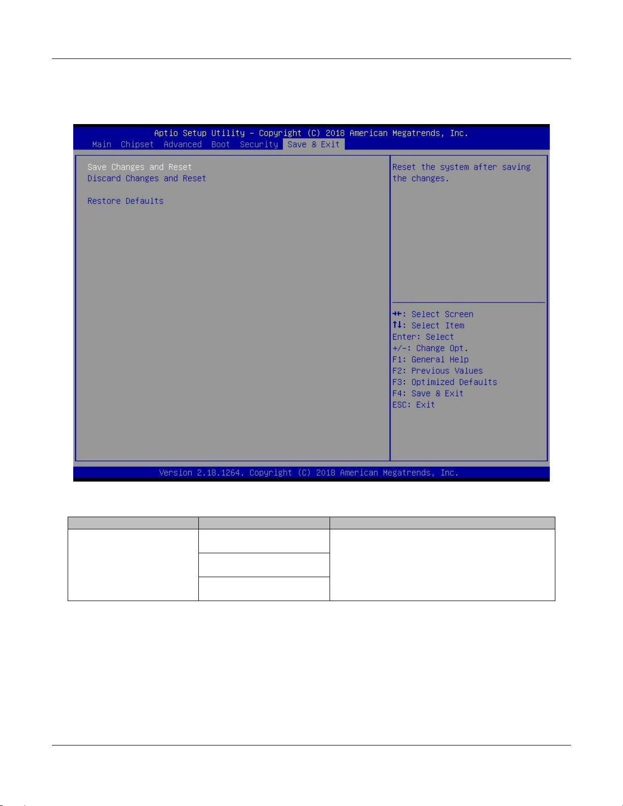
5.2.6. Save & Exit
The Save & Exit screens contain save and exit options.
Save & Exit
Screen Name
Options
Description
Save & Exit
Save Changes and Reset
Save changes and exit, discard changes and
exit, or discard changes
Discard Changes and
Reset
Restore Deaults

TEK3-BSW HARDWARE MANUAL – VER 1.00 APR 15 2019
Page 33 of 37
6. Mounting
This section describes the mounting procedures for the TEK3-BSW. The material in area of the mounting
must provide sufficient strength for safe mounting of this device.
6.1. Surface Mounting
There are 4 mounting holes (M5) on the front side of the device required for surface mounting. Four M4 or
M5 screws with at least 8mm head-to-tip length are required to secure this device to the surface.
Top view:
1 2
3 4
6.2. DIN Mounting
The device can be mounted on a DIN rail by using a DIN-rail bracket. There are four mounting holes (M3)
on the rear side of the device required for DIN bracket mounting (30mm DIN rail standard). Secure the
DIN bracket to the back of this device by using two M3 screws with at least 5mm head-to-tip length.
Bottom view:
1
2 3
4

TEK3-BSW HARDWARE MANUAL – VER 1.00 APR 15 2019
Page 34 of 37
7. Ordering Information
The TEK3-BSW is available in several configurations. Please contact your TechNexion sales contact
window or distributor for options and availability details.
7.1. Custom Part Number Rule
The TEK3-BSW can be ordered in custom tailored configuration to meet special application requirements
and conditions according to the following custom part number creation rules.
Custom part numbers carry minimum order quantities (MOQ). Please connect with your TechNexion
distributor or account manager for conditions and availability. Part number format:
TEK3-xxxxx-Rxx-Lxxx-xxx-xxxx-xxxx-xxxx-xxxx
Interface
Code
Description
Processor
E8000
Intel Atom x5-E8000
N3710
Intel Pentium N3710
Memory
R20
2GB SO-DIMM DDR3L
R40
4GB SO-DIMM DDR3L
R80
8GB SO-DIMM DDR3L
Power Expansion
L112
TXR-P1-12V-LAN1 (12V 3A)
L130
TXR-P1-1030V-LAN1 (8-36V 5A)
LPOE
TXR-P1-12V-POE1 (12V 3A) or (PoE 802.3at)
Storage eMMC
- - E32
eMMC 32GB (default)
E64
eMMC 64GB
Storage M.2 SSD
- - M064
M.2 SSD 64GB
M128
M.2 SSD 128GB
I/O Expansion
- - XS21
2x RS-232 + 8x GPIO
XG21
2x RS-232 + 8x GPIO (Galvanic Isolated)
Wi-Fi / Bluetooth
- - 9377
Qualcomm QCA9377 802.11a/b/g/n/ac (2.4 + 5GHz) + Bluetooth 5
Custom ID
XXXX
Custom Part number ID for customized software loader and special
component (BOM)

TEK3-BSW HARDWARE MANUAL – VER 1.00 APR 15 2019
Page 35 of 37
7.2. Standard Package Contents
Item
Partnumber
Description
1
TEK3-BSW
Fanless box PC computing system with Intel Braswell CPU
2
Accessoires
2x screw (M3) for M.2 card
1x rubber feet pad set
1x DC power latch cable (2-pin Micro-Fit 3.0)
NOTE: Pack contents might vary depending on your ordered configuration.

TEK3-BSW HARDWARE MANUAL – VER 1.00 APR 15 2019
Page 36 of 37
8. Important Notice
TechNexion reserve the right to make corrections, modifications, enhancements, improvements, and
other changes to its products and services at any time and to discontinue any product or service without
notice. Customers should obtain the latest relevant information before placing orders and should verify
that such information is current and complete. All products are sold subject to TechNexion terms and
conditions of sale supplied at the time of order acknowledgment.
TechNexion warrants performance of its hardware products to the specifications applicable at the time of
sale in accordance with TechNexion standard warranty. Testing and other quality control techniques are
used to the extent TechNexion deems necessary to support this warranty. Except where mandated by
government requirements, testing of all parameters of each product is not necessarily performed.
TechNexion assumes no liability for applications assistance or customer product design. Customers are
responsible for their products and applications using TechNexion components. To minimize the risks
associated with customer products and applications, customers should provide adequate design and
operating safeguards.
TechNexion does not warrant or represent that any license, either express or implied, is granted under
any TechNexion patent right, copyright, mask work right, or other TechNexion intellectual property right
relating to any combination, machine, or process in which TechNexion products or services are used.
Information published by TechNexion regarding third-party products or services does not constitute a
license from TechNexion to use such products or services or a warranty or endorsement thereof. Use of
such information may require a license from a third party under the patents or other intellectual property
of the third party, or a license from TechNexion under the patents or other intellectual property of
TechNexion.
TechNexion products are not authorized for use in safety-critical applications (such as life support) where
a failure of the TechNexion product would reasonably be expected to cause severe personal injury or
death, unless officers of the parties have executed an agreement specifically governing such use. Buyers
represent that they have all necessary expertise in the safety and regulatory ramifications of their
applications and acknowledge and agree that they are solely responsible for all legal, regulatory and
safety-related requirements concerning their products and any use of TechNexion products in such
safety-critical applications, notwithstanding any applications-related information or support that may be
provided by TechNexion. Further, Buyers must fully indemnify TechNexion and its representatives against
any damages arising out of the use of TechNexion products in such safety-critical applications.
TechNexion products are neither designed nor intended for use in military/aerospace applications or
environments unless the TechNexion products are specifically designated by TechNexion as military
grade or "enhanced plastic." Only products designated by TechNexion as military-grade meet military
specifications. Buyers acknowledge and agree that any such use of TechNexion products which
TechNexion has not designated as military-grade is solely at the Buyer's risk, and that they are solely
responsible for compliance with all legal and regulatory requirements in connection with such use.
TechNexion products are neither designed nor intended for use in automotive applications or
environments unless the specific TechNexion products are designated by TechNexion as compliant with
ISO/TS 16949 requirements. Buyers acknowledge and agree that, if they use any non-designated
products in automotive applications, TechNexion will not be responsible for any failure to meet such
requirements.

TEK3-BSW HARDWARE MANUAL – VER 1.00 APR 15 2019
Page 37 of 37
9. Disclaimer
© 2001-2019 TechNexion Ltd.
All Rights Reserved. No part of this document may be photocopied, reproduced, stored in a retrieval
system, or transmitted, in any form or by any means whether, electronic, mechanical, or otherwise without
the prior written permission of TechNexion Ltd.
No warranty of accuracy is given concerning the contents of the information contained in this publication.
To the extent permitted by law no liability (including liability to any person by reason of negligence) will be
accepted by TechNexion Ltd., its subsidiaries or employees for any direct or indirect loss or damage
caused by omissions from or inaccuracies in this document.
TechNexion Ltd. reserves the right to change details in this publication without notice.
Product and company names herein may be the trademarks of their respective owners.
TechNexion Ltd.
16F-5, No. 736, Zhongzheng Road,
ZhongHe District, 23511, New Taipei City, Taiwan
Phone : +886-2-82273585
Fax : +886-2-82273590
E-mail : sales@technexion.com
Web : https://www.technexion.com/
 Loading...