

Page 1
Your best partner for better driving
Update Date
2014.09.18
Model
QPI-BM09-1402-011
Firmware Date
BMW09CIC
Technetronix
Page 2
Warning
When installing the main unit, do not remove or alter existing
vehicle fasteners, including nuts, bolts, screw, clips, and fittings.
Never detach, move or alter existing vehicle wiring, including
electrical grounds and straps. Alteration of existing vehicle
components may make vehicle unsafe to operate. Should be
no any electronic devices or magnetic pole around installation
place.
Air bags are vital part of a safety system. Never install main unit
in a way which will alter air bag wiring or interfere with air bag
deployment. Air bags must function properly in the event of an
accident.
Before installing, check the location of pipe, tank, electrical
cables and others.
Read and follow the instruction manual.
Wiring location must not interfere driving, get in or out from car.
Use electrical tape to insulate the ends of all wires, even if they
are not used. Proper insulation prevents arcs, shocks and fires.
When installation is complete, test all vehicle electrical systems
to ensure they operate correctly, including lights, horn, brake
lights, and emergency flashers.
According to our sales policy, any problems caused by user’s
mistake, careless can not be guaranteed.
Caution
All steps of installation should be done by well-trained specialist.
During installation ignition key should be taken off and after all
installation finish connect power cable with interface for the last
step.
Do not install the main unit in places where it ma be exposed to
dew condensation (around the air conditioning hose, etc), or in
locations where it may come in contact with water, high levels of
moisture, dust or oily smoke
Install wiring in a manner in which cables will not come in contact
with metal parts. The wiring may be damaged by contact with
metal parts, resulting in fire and shocks. Avoid all contact with hot
surfaces when wiring the main unit. High temperatures may
damage wiring, causing shorts, arcing and fires.
Kindly check all parts are in the box, when receiving the product, if
anything missing, inform to the supplier or manufacturer.
Warning / Caution
Page 3
Table of Contents
1. Specifications
1.1 Main Specifications
1.2 Features
1.3 System Diagram
1.4 Components
1.5 Exterior
2. Installation
2.1 Installation Diagram
2.2 Installation
3. Settings
3.1 DIP Switch
3.2 Remote Control
3.3 Car Model and Navi Model
3.4 Factory Mode
3.5 DVD, DTV I-DRIVE input
3.6 Original Button Usage
3.7 Rear Camera
3.8 Rear Parking Guidelines
3.9 OSD
4. Trouble Shooting
4
5
6
7
9
10
11
13
14
15
16
19
21
22
24
25
27
Page 4

1. Specifications
1.1 Main Specifications
4
1. Compatibility
Most of brand-new cars coming with CIC Navigation
Computer System including BMW 5 series
2. Product composition
Multimedia Interface * 1ea
3. MULTIMEDIA INTERFACE input spec.
3 * A/V input (external video input)
1 * CVBS input (rear camera source input)
1 * RGB input (navigation system & HDMI)
1 * LCD input (car system input)
4. MULTIMEDIA INTERFACE output spec.
1 * LCD output
5. POWER spec.
input power : 8VDC ~ 18VDC
consumption power : 5 WATT
6. Switch input mode
- Input video skip function : able to select whether to
use the respective input video sources or not via DIP
switch.
- Able to change input modes via the remote control.
- Able to detect rear camera via CAN or rear lamp
cable.
- Able to change modes via an OEM Button
Page 5

1. Specifications
1.2 Features
5
Able to control NAVI, DVD, DTV function via Multimedia
Touch GUI
Able to adjust external image (DVD, NAVI) display on
screen
Improved Screen Display (user-oriented interface)
Mode change through original button
Provide power cables to connect with rear camera
Dynamic PAS(Parking assistance system)
Page 6
1. Specifications
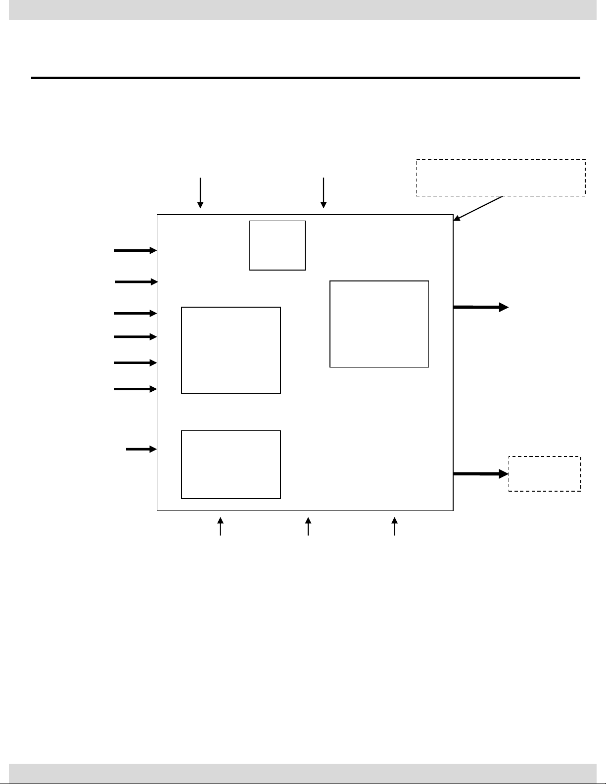
1.3 System Diagram
6
DISPLAY
A/V 1
NAVIGATION Input
(Analog RGB)
CVBS
(Rear camera)
Car Screen Input
(CAR MAIN BOARD)
A/V 2
A/V 3
VIDEO
CIRCUIT
VIDEO MUX
MCU
Power Input
(+8VDC ~ +18VDC)
POWER
CIRCUIT
Dip S/W
A/V OUT
HEADREST
MONITOR
Remote control
Switch for source toggle
OEM Button (Can Signal)
Car Installation
OEM LCD
Rear Camera Power
(+9VDC)
HDMI Input
(RGB-IN2)
Page 7
1. Specifications
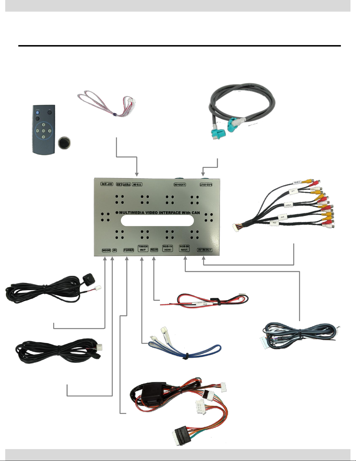
1.4 Components
A/V cable * 1EA
Mode cable * 1EA
IR cable * 1EA
R-CAM POWER cable * 1EA
(HARETC0002)
(HAVCAB0002)
Remote control * 1ea
(REMOTE0001)
(HARETC0001)
(HIRCAB0002)
TOUCH OUT cable * 1ea
(HTOUCH0004)
TOUCH IN cable * 1ea
(HTOUCH0009)
RGB cable * 1ea
(HRGBCA0013)
7
LCD cable * 1ea
(HLCDCA0005)
Modified POWER cable * 1EA
(HPOWER0012) , (HPOWER0021)
BMW09CIC
Page 8
1. Specifications
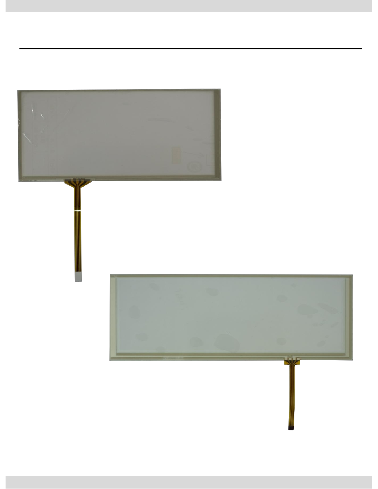
1.4 Components
8
6.5” Touch Panel
(TOUPAN0003)
8.8” Touch Panel
(TOULCD0011)
Page 9
1. Specifications
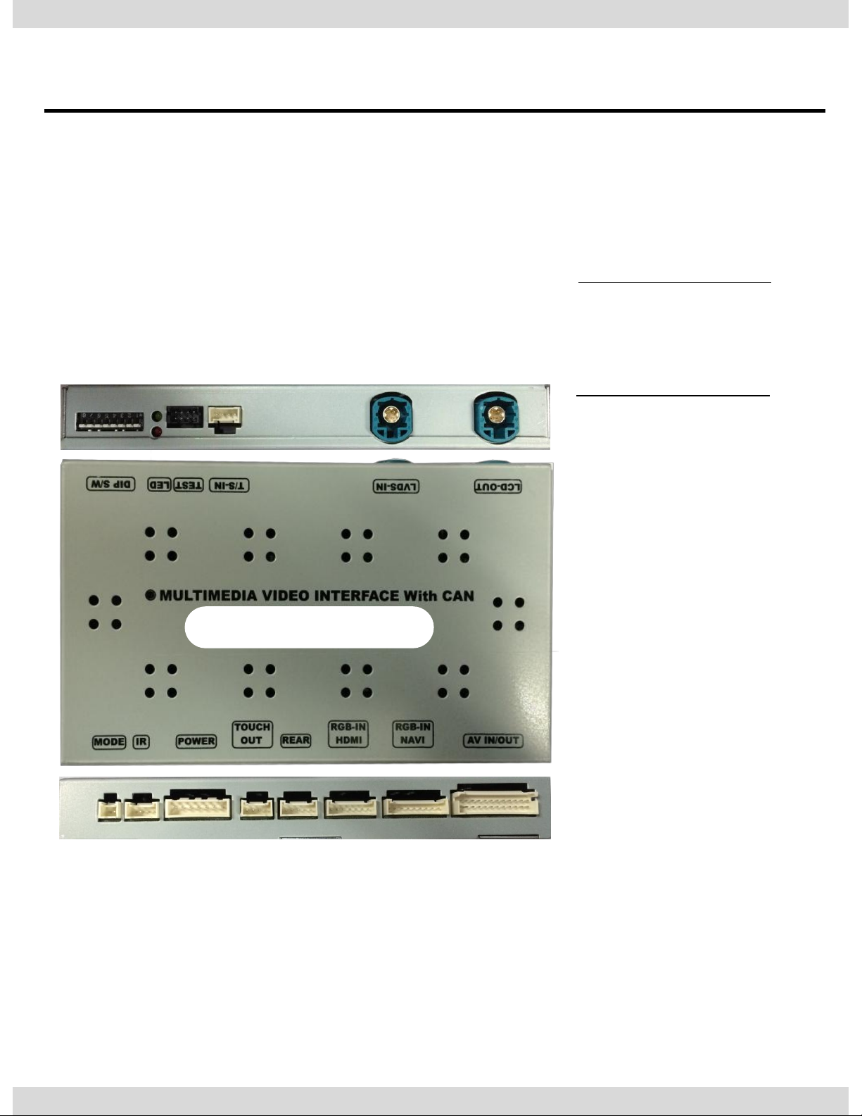
1.5 Exterior
① ⑥ ⑦ ⑧
⑨ ⑩ ⑪ ⑫
① MODE
② IR
③ POWER
④ TOUCH OUT
⑤ REAR
⑥ RGB-IN HDMI
⑦ RGB-IN NAVI
⑧ AV IN/OUT
⑨ LCD-OUT
⑪ T/S-IN
Dimension
Width 150.4mm
Length 99.4mm
Height 2.3.2mm
⑬
⑩ LCD-IN
② ③ ④ ⑤
⑫ TEST
⑬ LED
9
⑭
⑬ DIP S/W
BMW09CIC
Page 10
2. Installation
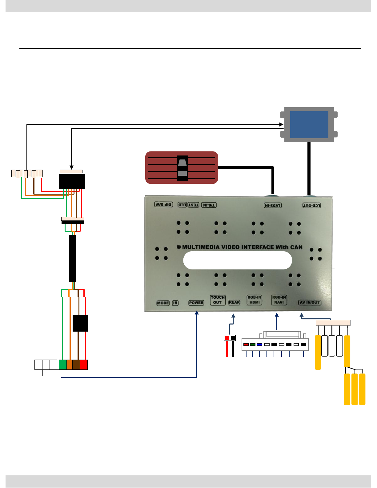
2.1 Installation Diagram
10
Offered
LCD Cable
Original
Monitor
AV1
AV2
AV3
REAR C
Audio L
Audio R
AV/OUT
Video
REAR (12V OUT)
GND
B DATA (blue) SYNC
GND
IR-DTV
NAVI-VS
IR-NAVI
IR-DVD
R DATA (red) G DATA (green)
Original LCD Cable
GND
ACC
CAN
CAN
Noise filter
Box
Connecting the original POWER & CAN cable to this part.
Connecting this to the spot which the original POWER & CAN cable was connected.
Control Box
BMW09CIC
Page 11
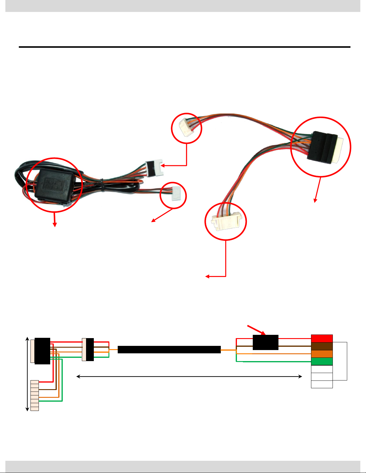
2. Installation
2.2 Installation / Connection of Power cable
11
NOISE FILTER BOX
This has to be connected
to the spot located at the
back of the monitor which
the original power & CAN
cable originally connected.
The original
power& CAN
cable has to be
connected to this
part.
Approximately 1M
GND
ACC
CAN(L)
CAN(H)
Noise
filter box
약 15cm
Connection to the interface
Connect
Page 12
Page 13
2. Installation
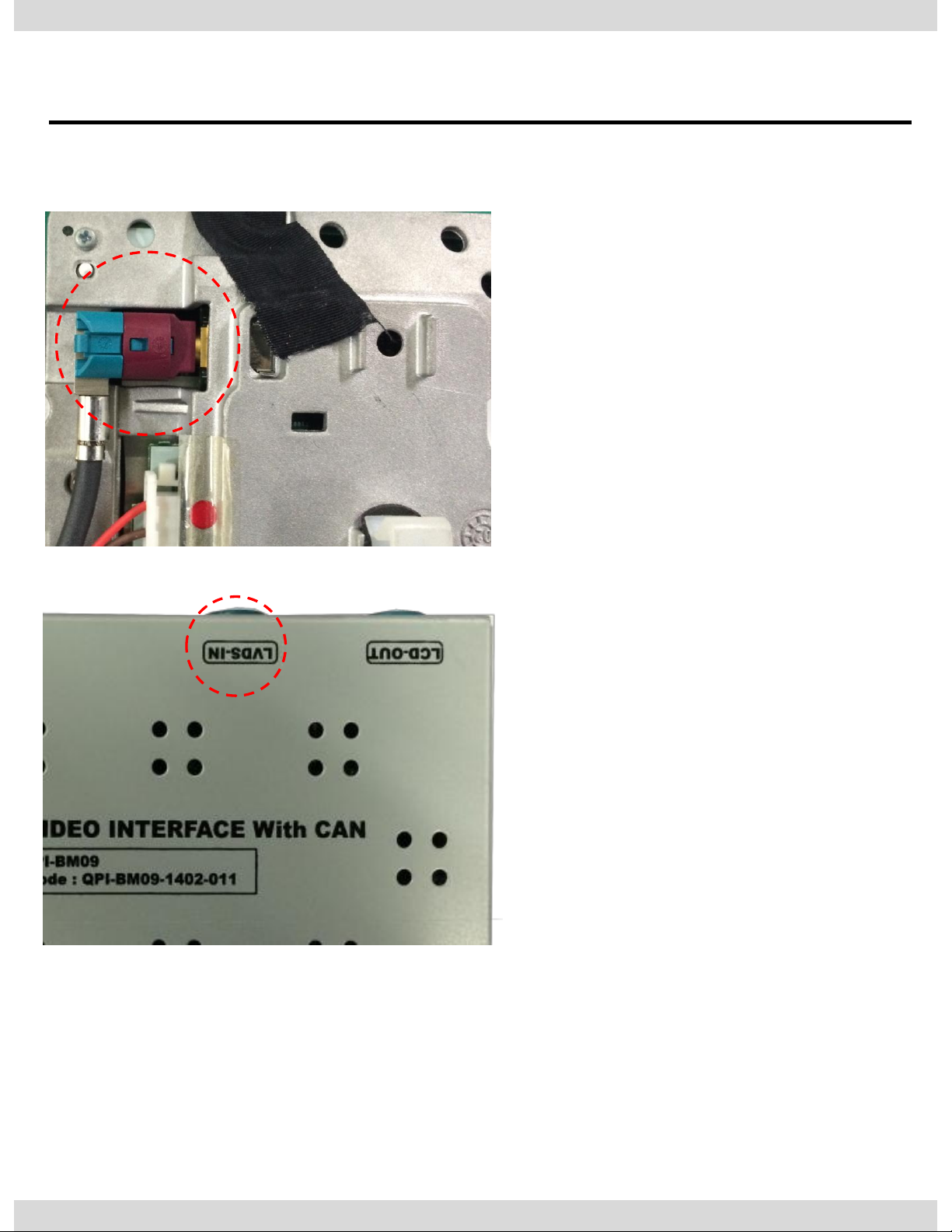
2.2 Installation / Monitor and Interface connection
① See left picture, Remove
original LCD cable from
monitor and connect with
provided LCD cable.
② Connect the original LCD
cable with LCD-IN on the
interface.
※ Precaution : Do not connect power cable with accessory
power, connect with backside of command or cigar jack.
12
Page 14
3. Settings
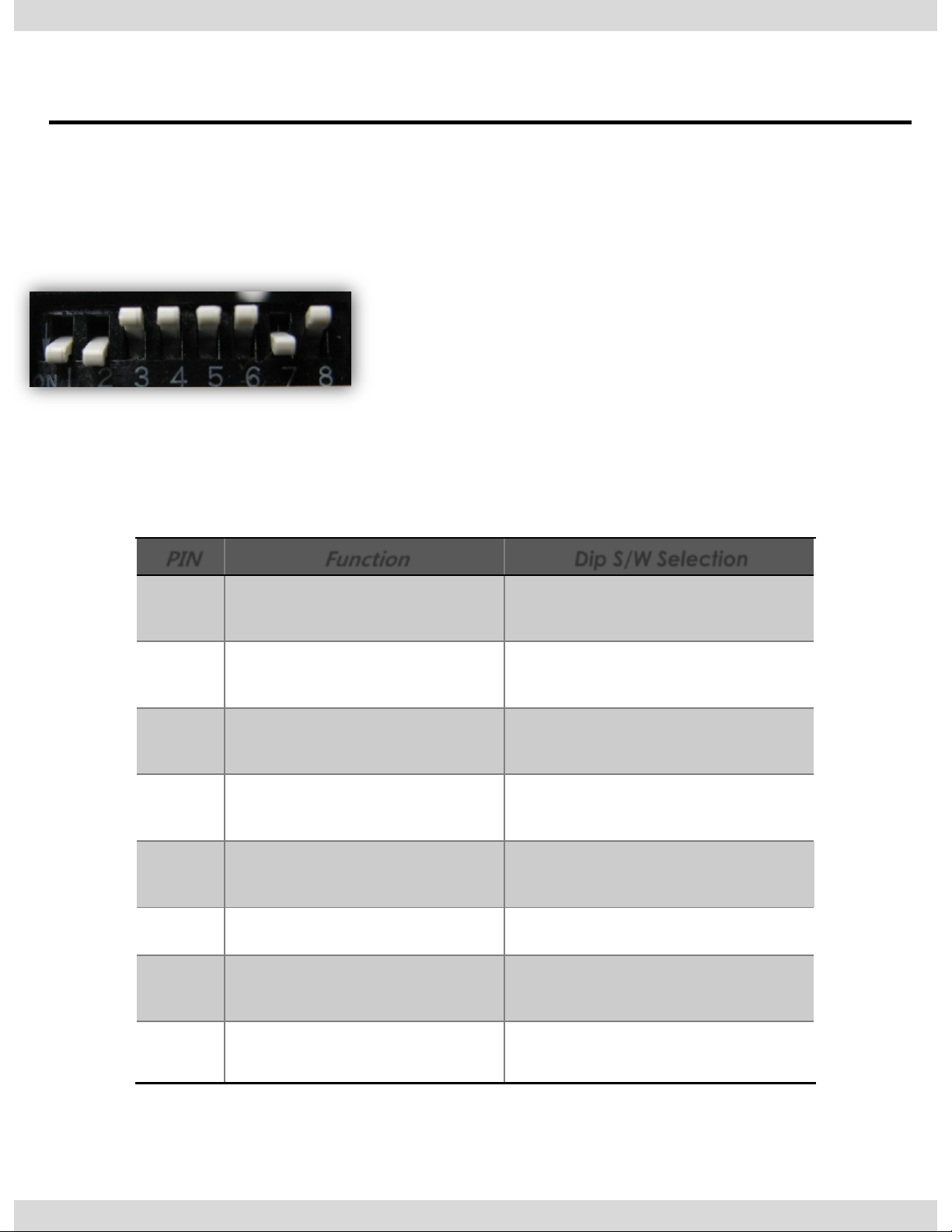
3.1 DIP Switch
PIN
Function
Dip S/W Selection
1
Displaying RGB input
ON : RGB mode skip
OFF : RGB mode display
2
Displaying A/V 1
ON : A/V 1 mode skip
OFF : A/V1 mode display
3
Displaying A/V 2
ON : A/V 2 mode skip
OFF : A/V2 mode display
4
Displaying A/V 3
ON : A/V 3 mode skip
OFF : A/V3 mode display
5
Setup of monitor size
ON : 7.2 inch
OFF : 10.2 inch
6
Select MINI model
ON : Select MINI car
7
Setup of rear camera use
ON : CVBS4
OFF : MAIN
8
Setting up display image
ON : By MUX (ON:DEFAULT)
OFF : By Relay
※ ON : DOWN / OFF : UP
Default : DIP S/W 8 OFF
※ Example DIP S/W usage
- Use input mode : A/V2, A/V3
- Use original navigation
- External rear camera
▷DIP S/W : 1,2 ON (Hide INPUT MODE)
▷DIP S/W : 3 OFF (A/V2 display)
▷DIP S/W : 4 OFF (A/V3 display)
▷DIP S/W : 5,6 OFF
▷DIP S/W : 7 ON (display external rear cam)
▷DIP S/W : 8 OFF
13
※ Please make sure to disconnect the power cable of the interface and reconnect
the power cable again to apply the dip switch setting whenever changing DIP switch.
Otherwise, DIP switch setting will not be applied.
Page 15
3. Settings
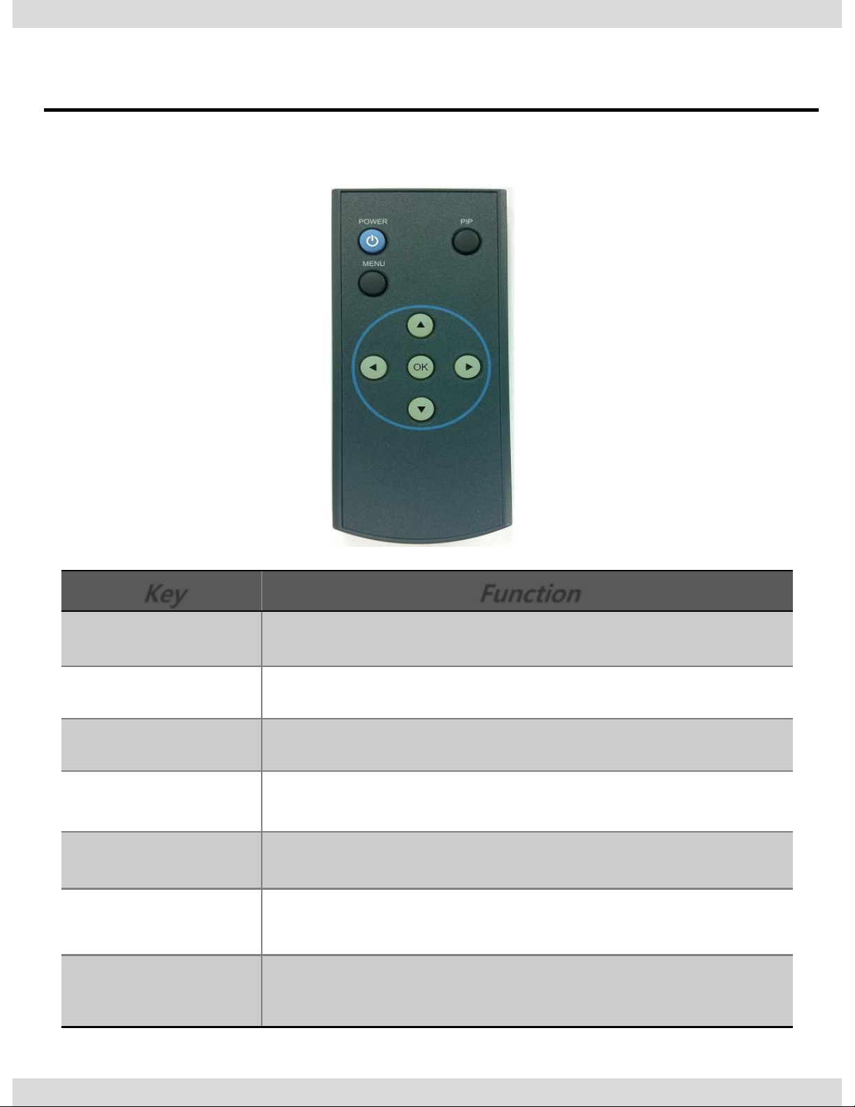
3.2 Remote Control
Key
Function
POWER & PIP Unavailable
MENU Activating OSD menu
OK Making a selection, changing image display
▲ Moving upward
▼
Moving downward
◀
Moving leftward
(If you press this button 2 seconds long, you can access the factory
mode.)
▶
Moving rightward
(If you press this button 2 seconds long, you can reset all the
data about user environment.)
14
Page 16
3. Settings
3.3 Car Model and Navi Model
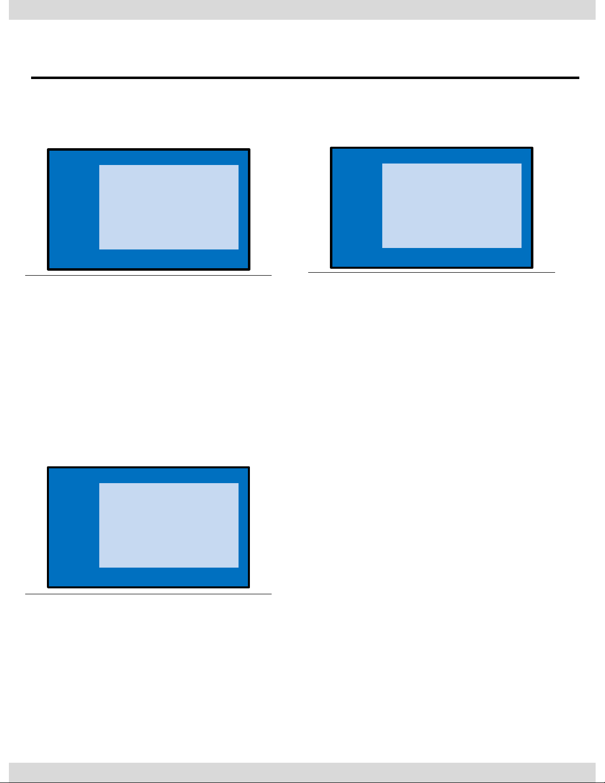
IMAGE
Adjust navigation position and size
H-POSITION : Move display horizontally
V-POSITION : Move display vertically
H-SIZE : Adjust navi size horizontally
UTIL1 - CAR MODEL
Selecting model of the car
F10 : 5 Series 2009~2012
E90 : No use
* Set pin#5 of DIP switch to the
right size of the monitor after
selecting model of the car.
(Refer to page9.)
UTIL1 – NAVI MODEL
Select of the navigation Model
DEFAULT
PAPAGO(WVGA)
NAVIST OEM(WVGA)
GN-3000(WVGA)
ICUBE(WVGA)
NAV-506TP(WVGA)
MYVI(WVGA)
WP9200(WVGA)
HDMI(WVGA)
GI-8000N 3D(WVGA)
GI-5000A(WVGA)
A-CLASS(WVGA)
KD-900(WVGA)
PAPAGO(WQVGA)
LS-901(WQVGA)
* Go into FACTORY/ UTIL1 (as
shown right) and adjust the
position and the size of the
navigation after setting the
definition of the navigation
FACTORY mode – Press ◀ button 2 seconds long on the remote control.
Setup for car model
Setup for navigation
15
IMAGE
PARK
UTIL1
UTIL2
INFO
NAVI MODEL
CAR MODEL
AVOUT SELECT
HDMI SKIP
FACTORY RESET
Menu of FACTORY
MENU to Return SEL to Select/Save
IMAGE
PARK
UTIL1
UTIL2
INFO
NAVI MODEL
CAR MODEL
AVOUT SELECT
HDMI SKIP
FACTORY RESET
Menu of FACTORY
MENU to Return SEL to Select/Save
IMAGE
PARK
UTIL
INFO
H-POSITION
V-POSITION
H-SIZE(NAVI)
Menu of FACTORY
MENU to Return SEL to Select/Save
Page 17
3. Settings
3.4 FACTORY Mode
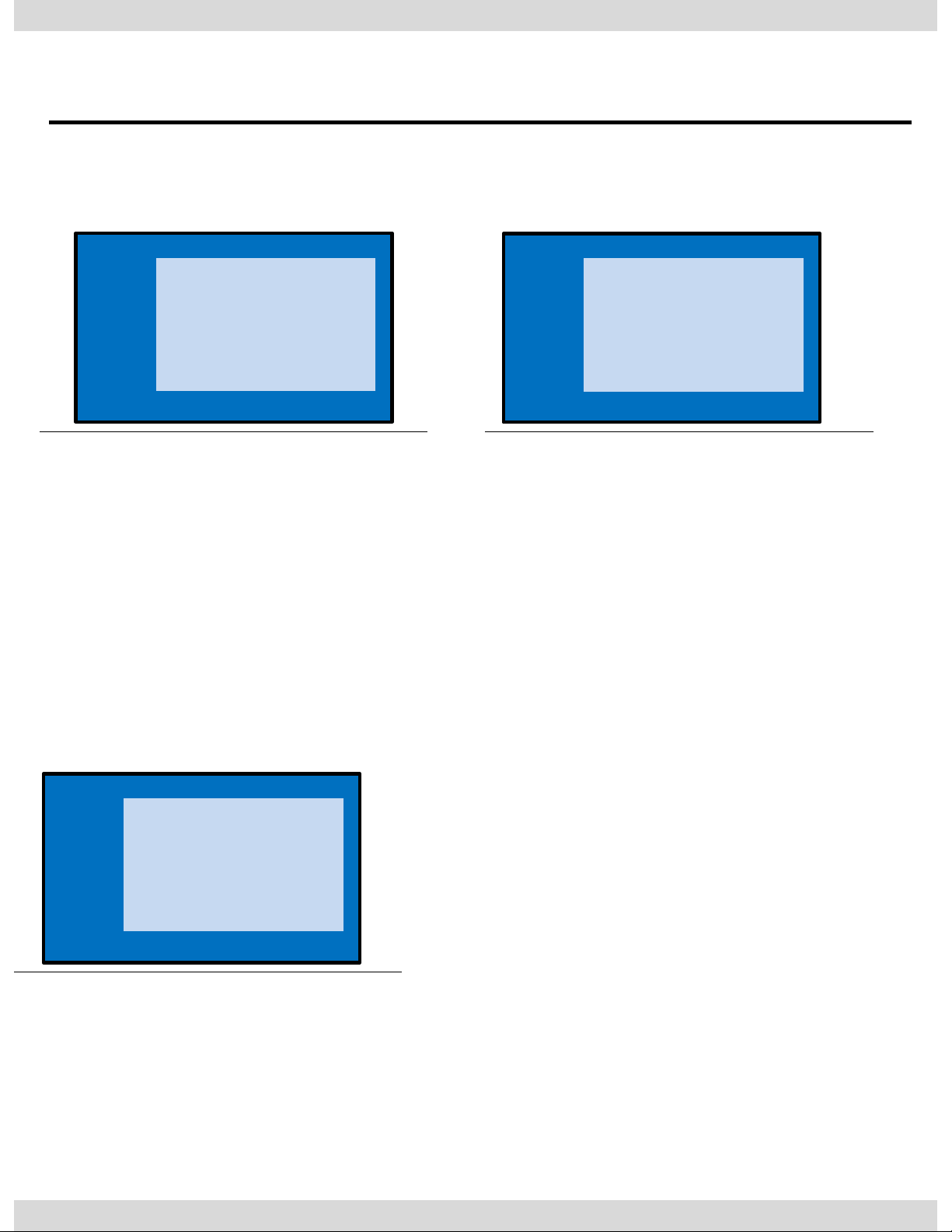
UTIL1 – AVOUT SELECT
Selecting background sound After
returning navigation or original
mode
DEFAULT : Selecting AV sound just
before changing navigation or
original mode from the AV mode
AV 1~3 : Sound of the selected
AV source 1~3
FACTORY mode – Press ◀ button 2 seconds long on the remote control.
16
IMAGE
PARK
UTIL1
UTIL2
INFO
NAVI MODEL
CAR MODEL
AVOUT SELECT
HDMI SKIP
FACTORY RESET
Menu of FACTORY
MENU to Return SEL to Select/Save
IMAGE
PARK
UTIL1
UTIL2
INFO
NAVI MODEL
CAR MODEL
AVOUT SELECT
HDMI SKIP
FACTORY RESET
Menu of FACTORY
MENU to Return SEL to Select/Save
IMAGE
PARK
UTIL1
UTIL2
INFO
NAVI MODEL
CAR MODEL
AVOUT SELECT
HDMI SKIP
FACTORY RESET
Menu of FACTORY
MENU to Return SEL to Select/Save
UTIL1 – HDMI SKIP
Selecting the use of HDMI mode
ON / OFF
UTIL1 - FACTORY RESET
- Reset
※ Long press the ▶ button
Page 18
3. Settings
3.4 FACTORY Mode
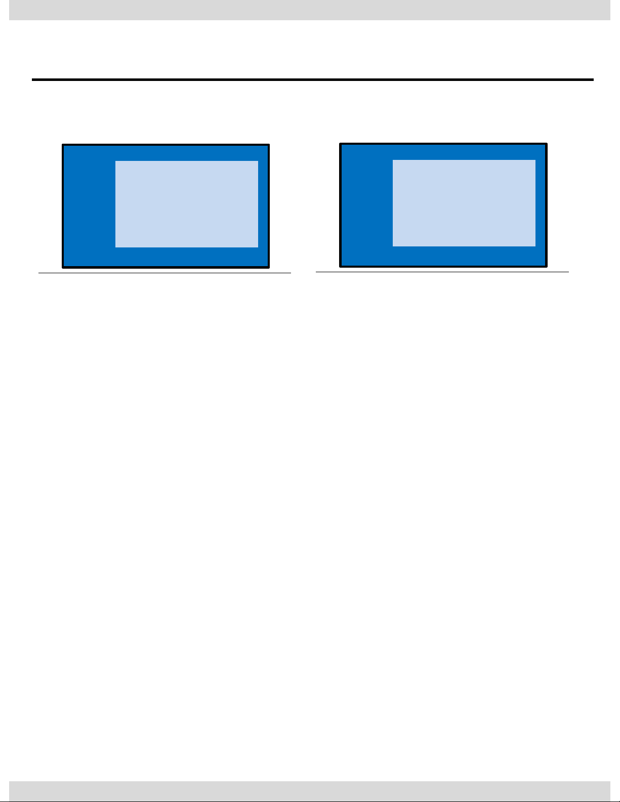
UTIL2 - I_DRV CONTROL
Selecting whether to use I_DRV
function or not
ON / OFF
A/V1 : Control DVD Remote control
UI
A/V2 : Control DTV Remote control
UI
UTIL2 - I_DRV REMOTE
Choose DTV and DVD model
to be control I_DRV function
• Select DVD model: Setting on
AV1 Mode
• Select DTV model : Setting on
A/V2 mode
FACTORY mode – Press ◀ button 2 seconds long on the remote control.
17
IMAGE
PARK
UTIL1
UTIL2
INFO
I-DRV REMOTE
I-DRV CONTROL
IR MEMORY
HANDLE KEY
MEMORY KEY
CALIBRATE
Menu of FACTORY
MENU to Return SEL to Select/Save
IMAGE
PARK
UTIL1
UTIL2
INFO
I-DRV REMOTE
I-DRV CONTROL
IR MEMORY
HANDLE KEY
MEMORY KEY
CALIBRATE
Menu of FACTORY
MENU to Return SEL to Select/Save
Page 19

3. Settings
3.4 FACTORY Mode
FACTORY mode – Press ◀ button 2 seconds long on the remote control.
UTIL2 – HANDLE KEY
Whether to use voice button
on handle for mode change
ON / OFF
UTIL2 – IR MEMORY
To register DVD, DTV remote control,
the remote control value must be
registered and can be control with
I-Drive
DVD(A/V1), DTV(A/V2)
※ To use this function, in UTIL2I_DRV REMOTE select USER mode
(Connect IR of DVD / DTV to
Remote control.
UTIL2 – MEMORY KEY
Wheter to use car audio
button #8 (mode change +
aux change)
ON / OFF
UTIL2 – CALIBRATE
Touch Calibration
YES / NO
18
IMAGE
PARK
UTIL1
UTIL2
INFO
I-DRV REMOTE
I-DRV CONTROL
IR MEMORY
HANDLE KEY
MEMORY KEY
CALIBRATE
Menu of FACTORY
MENU to Return SEL to Select/Save
IMAGE
PARK
UTIL1
UTIL2
INFO
I-DRV REMOTE
I-DRV CONTROL
IR MEMORY
HANDLE KEY
MEMORY KEY
CALIBRATE
Menu of FACTORY
MENU to Return SEL to Select/Save
IMAGE
PARK
UTIL1
UTIL2
INFO
I-DRV REMOTE
I-DRV CONTROL
IR MEMORY
HANDLE KEY
MEMORY KEY
CALIBRATE
Menu of FACTORY
MENU to Return SEL to Select/Save
IMAGE
PARK
UTIL1
UTIL2
INFO
I-DRV REMOTE
I-DRV CONTROL
IR MEMORY
HANDLE KEY
MEMORY KEY
CALIBRATE
Menu of FACTORY
MENU to Return SEL to Select/Save
Page 20
3. Settings
3.5 DVD, DTV IR MEMORY input
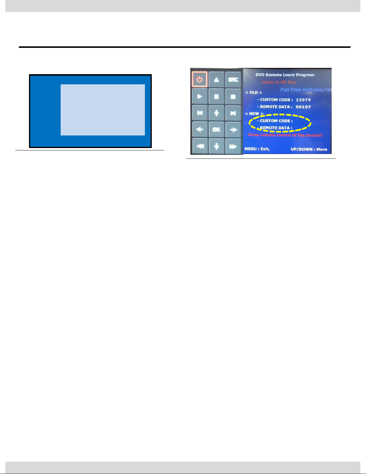
① First of all, press ◀ button on
remote controller 2 seconds
long or press
UP→DOWN→UP→MENU
button in order to access
Factory mode. Choose IR
MEMORY on UTIL2.
In IR MEMORY, you can choose
AV source of DTV and DVD you
want to use.
② Picture above shows DVD
remote control button value
input, select menu you want
to save. (To register DVD
remote control button value,
select IR MEMORY – DTV and
follow below instructions.
Example)
a. After select OK button on
OSD menu, press intended IDrive button
b. Indicated part above will
flicker, and press POWER on
DVD remote control.
(continue to next page)
What is IR-MEMORY Mode?
Is to allow I-Drive and touch screen to control other DVD or DTV
(besides the existing,; for example : SANYO, NECVOX) by register
remote control value.
19
IMAGE
PARK
UTIL1
UTIL2
INFO
I-DRV REMOTE
I-DRV CONTROL
IR MEMORY
HANDLE KEY
MEMORY KEY
CALIBRATE
Menu of FACTORY
MENU to Return SEL to Select/Save
Page 21
3. Settings
3.5 DVD, DTV I-DRIVE input
example) continued..
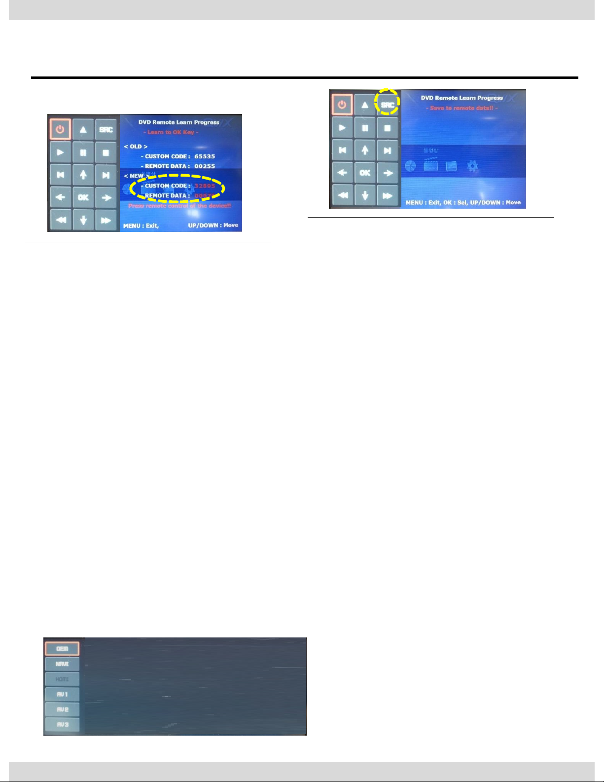
c. The values that you
registered will appear as
green text in the marked
area on pressing the button.
And the values will be saved
automatically.
d. Register remain buttons’
value in OSD menu like the
above-mentioned.
③ After register, select “SRC”
button in OSD menu. Then you
can see confirmation window
as shown above. At the
moment,
(If data is saved, DVD TYPE and
DTV TYPE will be changed to
“USER” automatically.)
If you see “SUCCESS” on screen,
the data is saved clearly and
you can control DVD via touch
screen. BUT, you MUST change
the option in FACTORY-UTIL2I_DRV REMOTE to “USER”.
※ When touch the screen, you can control DVD, DTV using remote control UI
via touch screen or I-Drive
(6.5” monitor – Touch the middle of the screen,
8.8”, 10.2” monitor – Touch the left side of the screen)
※ If touch the screen in DVD(A/V1), DTV(A/V2) mode, Can see remote control UI
If touch the screen in RGB(HDMI), A/V3 mode, Can see mode switching UI
- If you want to see mode switching UI in DVD, DTV mode, Select “SRC” button
20
Page 22
3. Settings
3.6 Original Button Usage
21
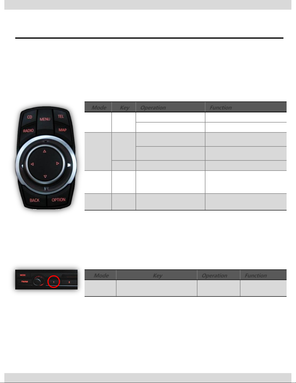
I-Drive Button(All models)
Hot Key Function
Mode
Key
Operation
Function
All
modes
MENU
Long Press
Mode change
Short Press
back to original image
DMB
△
Long Press
Scan Channel
Short Press
Channel up
▽
Short Press
Channel down
AV1
AV2
AV3
▽
Long press
Operate PIP Function
Reverse
Mode
▽
Long press
Operate PIP Function
Mode
Key
Operation
Function
All
Modes
# 8 button located beside
Radio button
Short Press
Switch modes
Page 23
3. Settings
3.7 Rear Camera
22
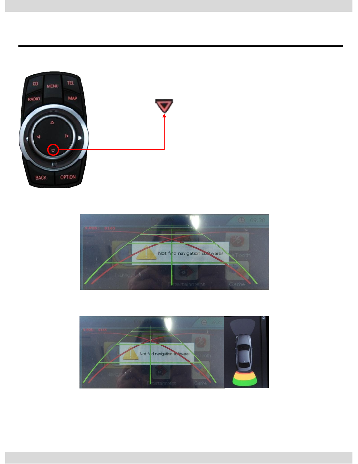
Setting up the screen option of Rear Image
5 Series(F10) : Long Press I-Drive to set up
<Full Image of Rear Camera>
<Rear Camera +PDC >
Page 24
3. Settings
3.7 Rear Camera
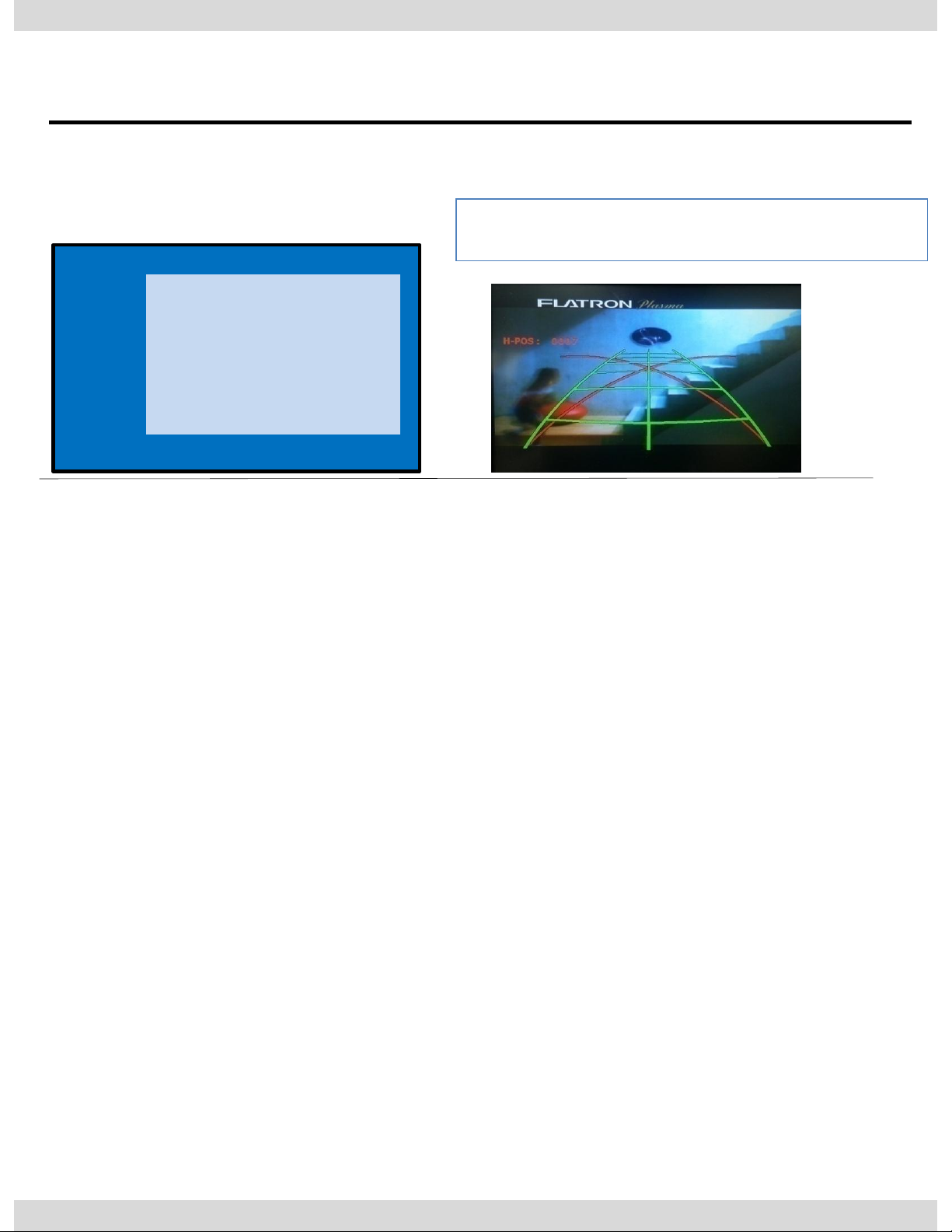
PARK
PAS TYPE : Selecting Type of parking guide line
- NOT USED : Not use Parking guide line
- PAS ON : Selecting Dynamic Parking guide line
- PAS OFF : Selecting fixed Parking guide line
PAS SETUP : Adjusting the position of the parking guide line (available in PARK SETUP->
V-POSITION, H-POSITION)
REAR TYPE : Choose rear camera recognition
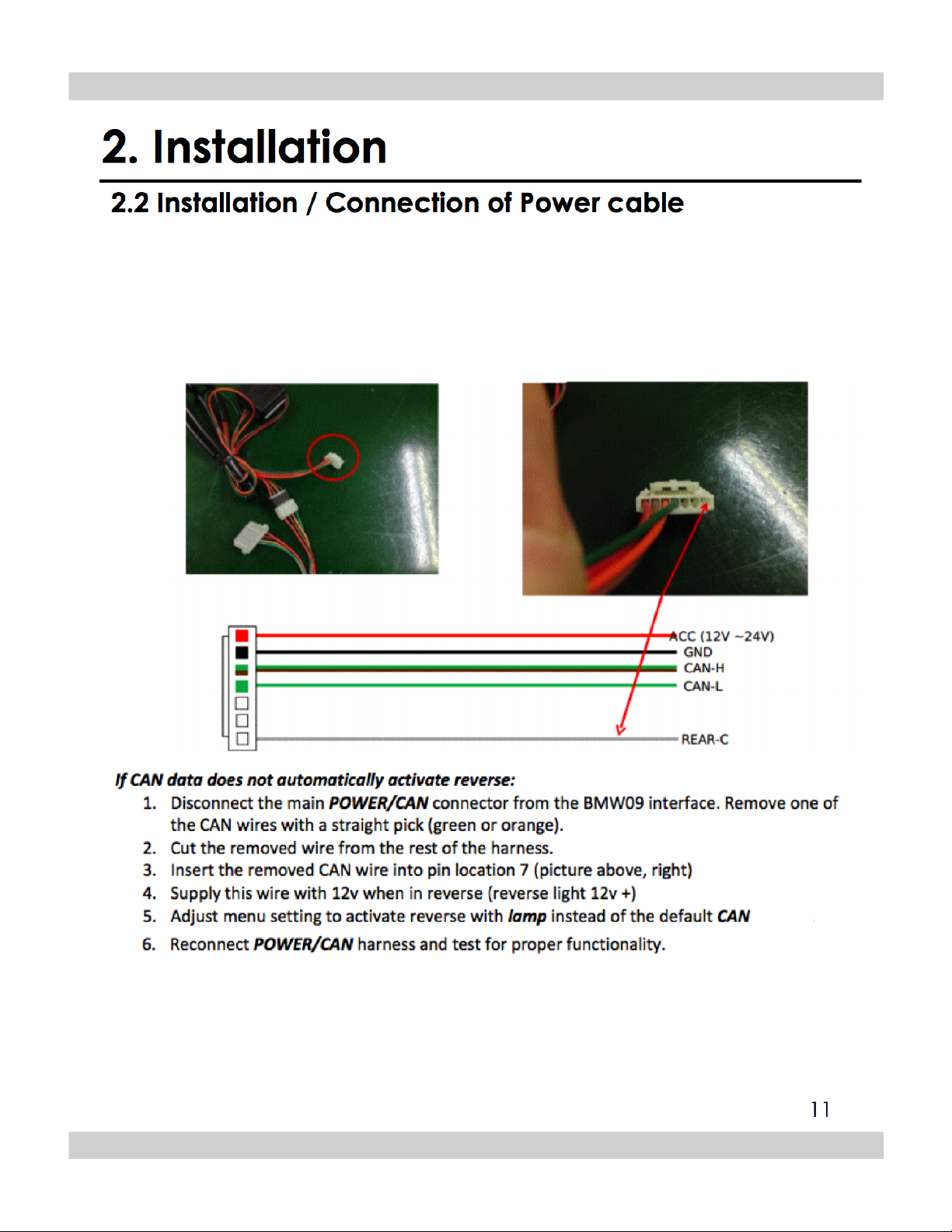
* LAMP - Detecting the rear view camera via rear lamp (Installer must connect
“Rear-C” cable of the power cable to the rear lamp of the car.)
*CAN - Detecting the rear view camera by CAN signal (Installer must connect
“CAN” cable of the power cable to the “CAN” cable of the car.)
SAFE ENABLE : If your car is connected with CAN cable and it is in ”ON” state, you can
NOT watch DVD or A/V except original image or navigation while
driving. At that time the screen use only main and navigation(default :
OFF)
CAMERA TYPE : When PDC mode, Selecting screen ratio
* OEM CAM : The car has original camera and install external camera
* EXT. CAM : The car doesn’t have original camera and install external camera
a. If you want to get to the FACTORY mode, set the gear as rear state and press “LEFT”
button 2 seconds long on the remote control or the keypad. (as shown left top)
FACTORY mode – Press ◀ button 2 seconds long on the remote control.
※After installing rear camera : DIP S/W #7
must be put down (ON). Refer to page 9.
23
IMAGE
PARK
UTIL1
UTIL2
INFO
PAS TYPE
PAS SETUP
REAR TYPE
SAFE ENABLE
RADAR ENABLE
Menu of FACTORY
MENU to Return SEL to Select/Save
Page 25
3. Settings
3.8 Parking guide Lines
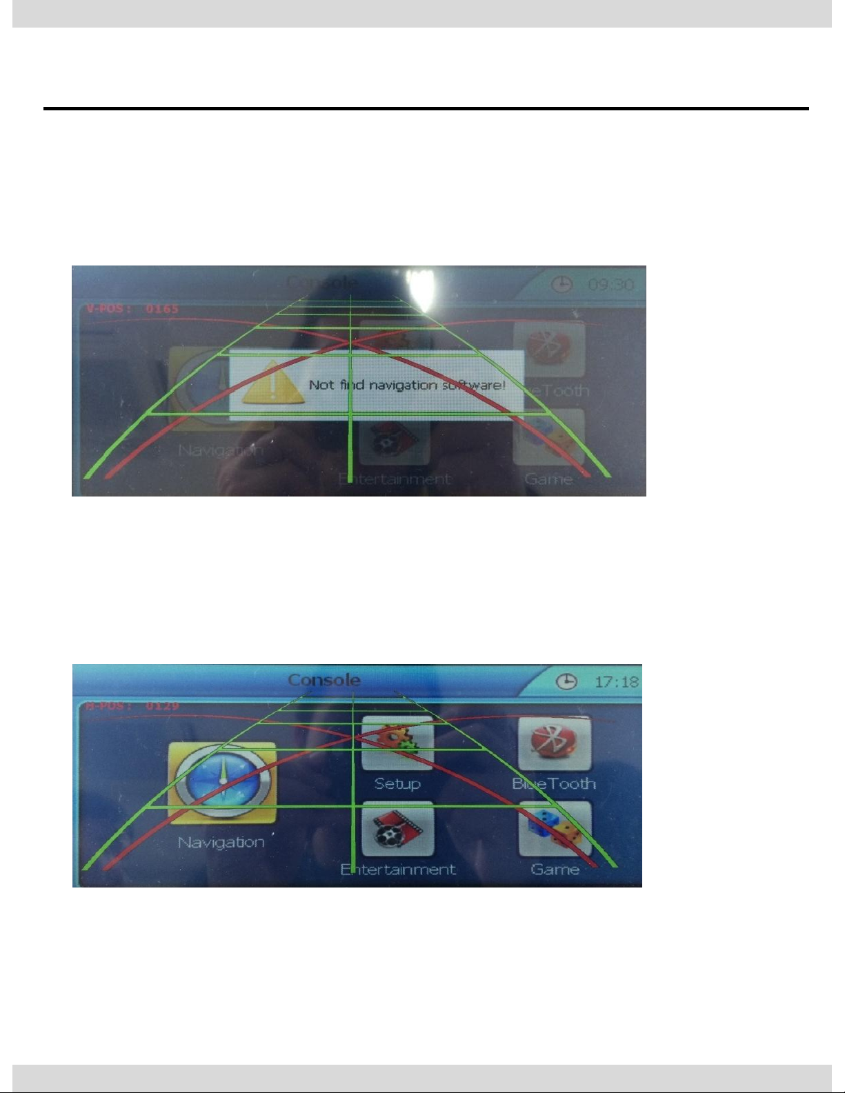
H-POS
V-POS
24
In H-POSITION, use ◁, ▷ on remote control, to adjust parking
guideline left and right.
Go to Factory Menu, choose PAS SETUP, by using OK button change
H-POS → V-POS
In V-POSITION use △, ▽on remote control, to adjust parking
guideline up and down.
Page 26
3. Settings
3.9 OSD (On Screen Display) / Analog RGB Mode
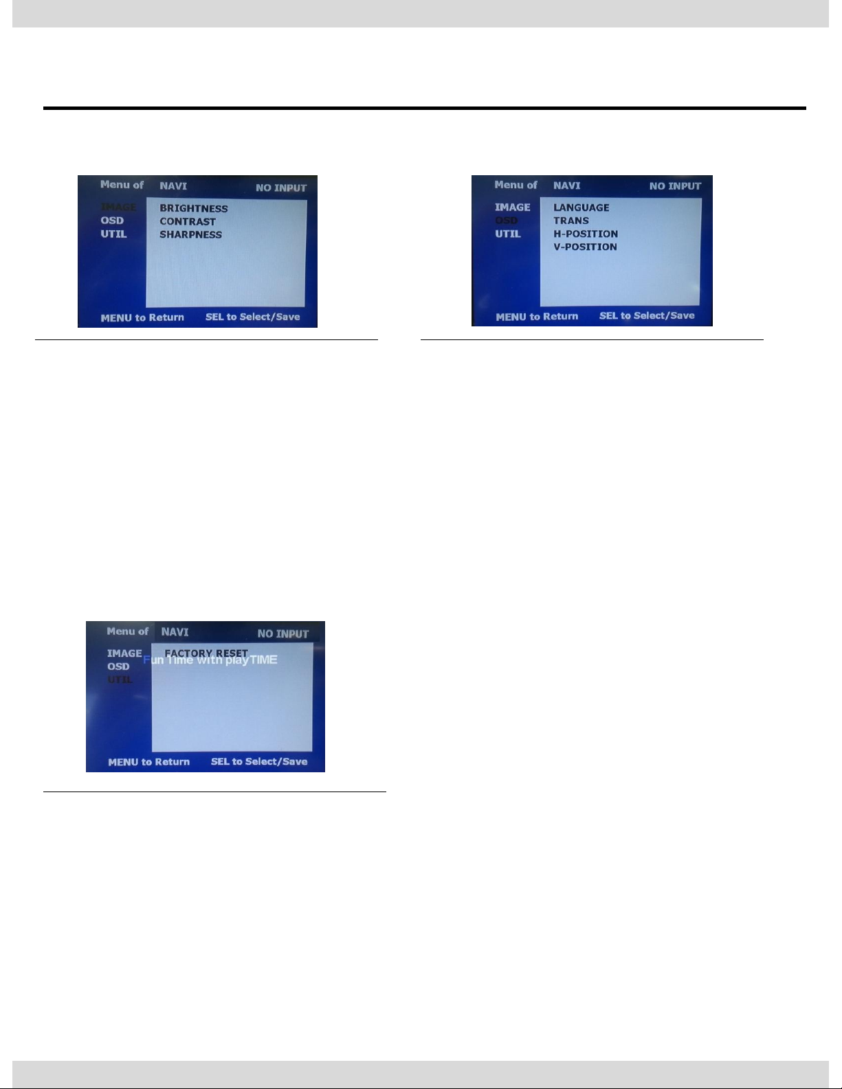
OSD
*LANGUAGE : Set OSD language
(only support English and Chinese)
* TRANS : Adjust OSD transparency
*H-POSITION : Move OSD horizontally
* V-POSITION : Move OSD vertically
IMAGE
* BRIGHTNESS
* CONTRAST
* SHARPNESS
UTIL
* FACTORY RESET
: Factory reset only for OSD function
(unable reset video position)
25
Page 27
3. Settings
3.9 OSD (On Screen Display) / Video Mode
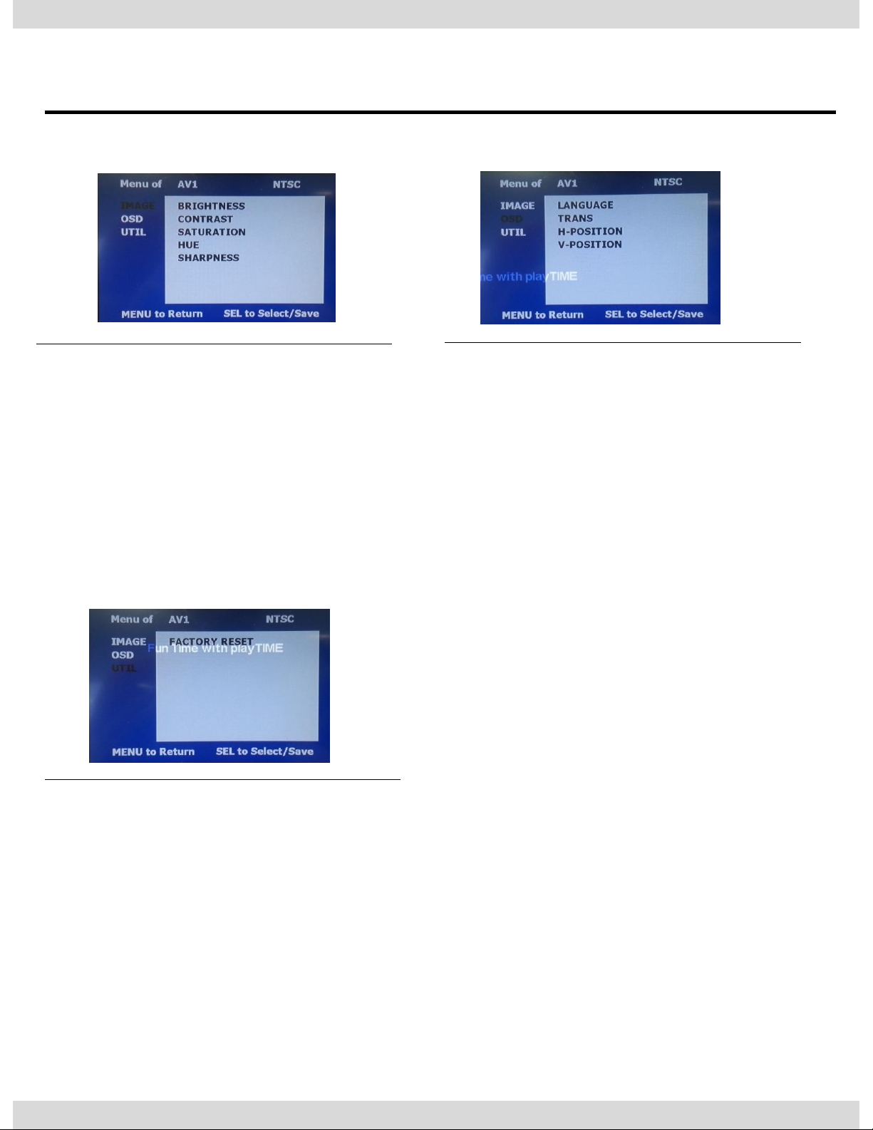
IMAGE
* BRIGHTNESS
* CONTRAST
* SATURATION
* HUE
* SHARPNESS
OSD
* LANGUAGE : Set OSD language
(only support English and Chinese)
* TRANS : Adjust OSD transparency
* H_POSITION : Move OSD horizontally
* V_POSITION : Move OSD vertically
UTIL
* FACTORY RESET
: Factory reset only for OSD function
(unable reset video position)
26
Page 28

4. Trouble Shooting
Q. I cannot change mode
A. Check connection of Ground cable and IR Cable.
Check LED lamp is on, if not check connection of POWER cable.
Q. All I got on the screen is black.
A. .Check second LED lamp of the interface is on, if not, check A/V sources
connected are working well.
(Second lamp indicates AV sources connected works well.) Check
interface connection has been done well.
Q. Displayed image color is not proper (too dark or unsuitable color)
A. Try to select “INITIAL” in OSD menu, if it does not work, inform to
manufacturer.
Q. I cannot watch the rear camera on the screen
A. Set the DIP switch #7 as state “ON”.
Q. Set mode not appear
A. Check DIP Switch.
Q. OEM image is not displayed.
A. Check interface’s LCD In/Out cable connection. If the status keeps on,
inform to manufacturer.
Q. Screen only displays white color.
A. Check LCD out cable is connected well, if this status keeps, inform to
manufacturer.
Q. Show PIP function via handle button, and original screen appear half only.
A. This is not because of faulty interface, please check original monitor split
function settings.
Q. After connect CAN cable, set gear “P”, video doesn’t appear.
A. Go to “FACTORY MODE”and check “UTIL-Rear Select”. Change
“LAMP”settings to “CAN” with remote control.
※ LAMP : In case of connecting “Rear-C” wire of Power Cable to Rear
Lamp in vehicle.
27
Page 29

RM #404 4TH FLOOR, B-DONG,
WOORIMLIONSVALLY, 371-28, GASAN-DONG,
GEUMCHEON-GU, SEOUL, KOREA.
TEL : 82-2-868-3627~9 | FAX : 82-2-2026-5987
Technetronix
 Loading...