

Page 1

BK MIKRO 5-RL
Tool Monitoring System
Technical Documentation - North American Edition
Revision 2.0
Released: April, 1997
553 Industrial Dr. Hartland, WI 53029 262-367-8665 fax 262-367-0208
web-site www.techna-tool.com email [email protected]
Page 2

Contents
Contents
1. DESCRIPTION......................................................................................................................................3
2. SYSTEM COMPONENTS .......................................................................................................................4
2.1. CONTROL UNIT......................................................................................................................................4
2.1.1. Characteristic Properties ................................................................................................................4
2.1.2. Technical Data..............................................................................................................................5
2.1.3. Scanner Socket............................................................................................................................5
2.1.4. Screw Terminals ...........................................................................................................................6
2.1.4.1. Power Supply.........................................................................................................................7
2.1.4.2. Control Inputs.........................................................................................................................8
2.1.4.3. Relay Outputs ........................................................................................................................8
2.1.5. Light -Emitting Diodes ....................................................................................................................8
2.1.6. Toggle Switches............................................................................................................................9
2.1.6.1. Switch "MODE 1" ...................................................................................................................9
2.1.6.2. Switch "MODE 2" ..................................................................................................................9
2.1.6.3. "Normally Open Contact/Normally Closed Contact" Switch .........................................................9
2.1.6.4. "Decel" Switch........................................................................................................................9
2.1.7. Notes on Technical Safety ...........................................................................................................10
NO ISOLATION FROM DC POWER SUPPLY.......................................................................................................... 10
2.2. SCANNER TK 5.................................................................................................................................... 11
2.2.1. Characteristic Properties ..............................................................................................................11
2.2.2. Technical Data............................................................................................................................ 12
2.3. CONNECTION CABLE............................................................................................................................. 12
3. FUNCTION.......................................................................................................................................... 13
3.1. TEACH-IN............................................................................................................................................ 13
3.2. START............................................................................................................................................... 13
3.3. SCANNING TIMES.................................................................................................................................. 14
3.4. STATUS INDICATION.............................................................................................................................. 14
3.4.1. Yellow LED................................................................................................................................. 14
3.4.2. Red/Green LED........................................................................................................................... 14
3.5. DEFLECTION OF WAND.......................................................................................................................... 14
4. INSTALLATION NOTES ......................................................................................................................15
4.1. CONTROL VOLTAGE CONNECTION............................................................................................................ 15
4.2. ELECTRICAL INTERFERENCE PREVENTION................................................................................................... 16
Appendix A Model 5 Manufacturing and Techna-Tool Part Numbers............................................................ 16
BK MIKRO 5-RL Page 1
Page 3

Contents
© Copyright 1997, Techna-Tool Inc., Hartland, Wisconsin, and MSC Tuttlingen GMBH i.Gr., Tuttlingen,
Germany.
The information in this document is subject to change without notice.
Page 2 BK MIKRO 5-RL
Page 4

Description
1. Description
BK MIKRO 5-RL is a tool monitoring system customized for simultaneous scanning of two tools.
The complete BK MIKRO 5-RL system comprises
• a control unit,
• a sensing head (scanner),
• a connection cable.
Principle of Operation
The system will monitor the presence of two particular tools. The monitoring system will first
determine the exact position of the tools by a "teach-in" cycle. This cycle is followed by sensormode, during which the sensing wand will be moved to the positions "just learned", and a comparison
takes place.
All output to the machine will be via two relay contacts, configurable as normally closed or normally
open. For machine control, the "O.K." relay, the "K.O." relay, or both may be used.
The zero position of the wand will be calculated during the "teach-in" cycle from the positions of the
two objects to be scanned. Starting from this position, any desired scanning angle can be
implemented.
Further features enabling customized system configuration include:
• Automatic detection of zero position (point of reference between scanning positions), or manually
established rest position.
• Relay contacts switch-selectable as normally open or normally closed.
• Two settings of controlled acceleration and deceleration.
• Detection of cable breaks.
BK MIKRO 5-RL Page 3
Page 5
System Components
2. System Components
2.1. Control Unit
+ –
Com LernStart
DC 24 V
Scanner
1 2
k.o.
AC 230 V
L1 N
AC 230 V
L1 N
Supply Voltage
(optional))
AC 120 V
L1 N
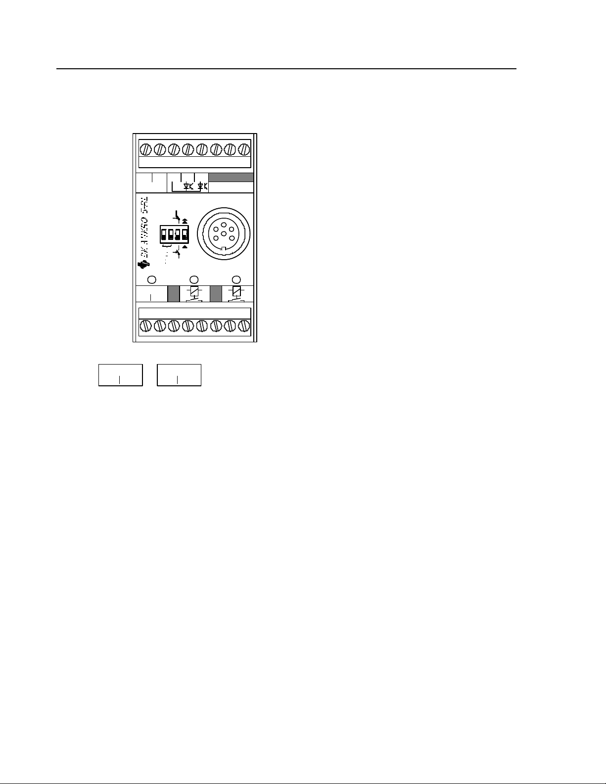
2.1.1. Characteristic Properties
The BK MIKRO 5 system control unit is housed in an insulating material housing. On its front panel,
the control unit is fitted with screw terminals to connect all machine inputs and outputs, supply
voltage, and the scanner.
Note:
The unit is available in three different models for three different supply voltages:
24 VDC, 120 VAC, 230 VAC.
Sensing Head Socket
o.k.
Page 4 BK MIKRO 5-RL
Page 6
System Components
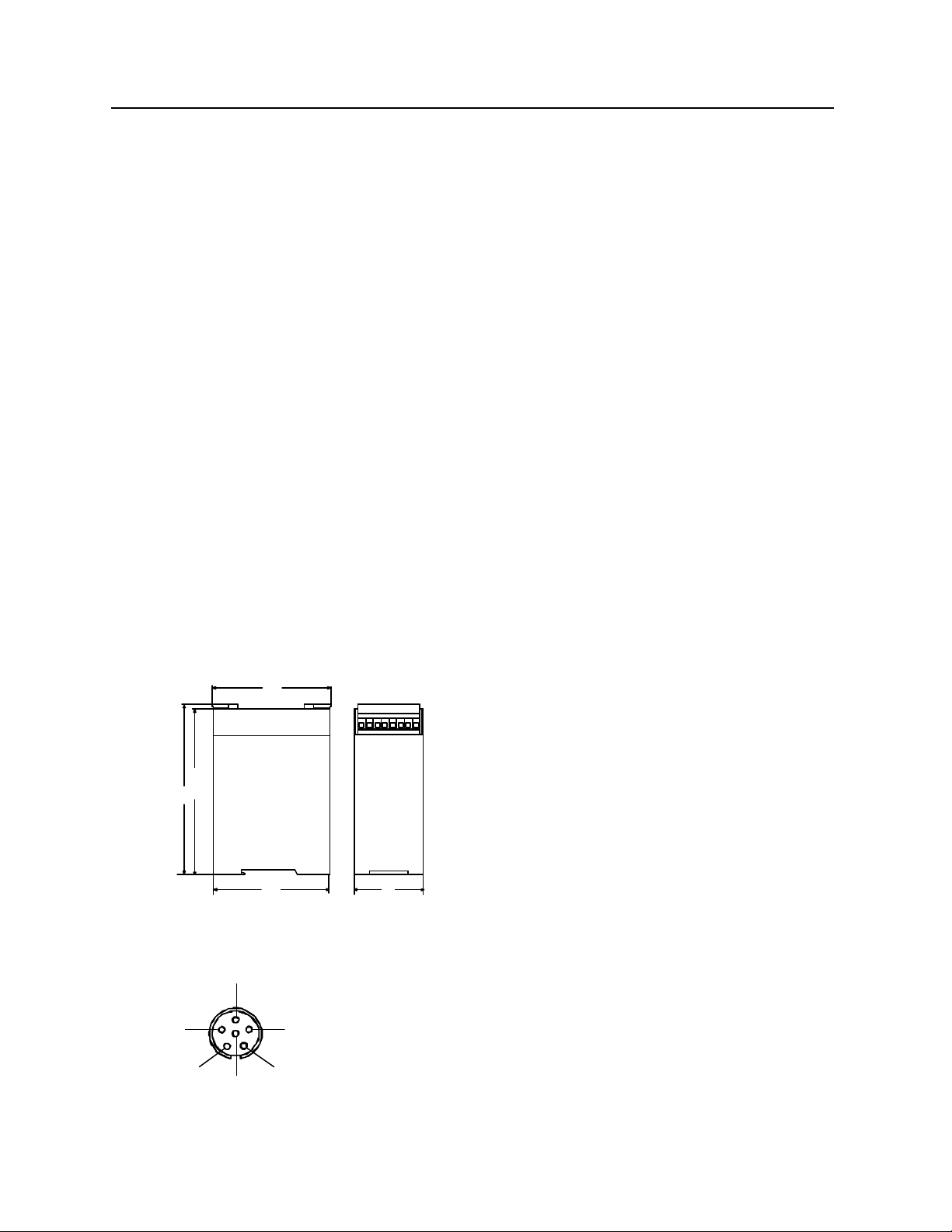
2.1.2. Technical Data
Housing........................................Insulated Material Housing, Protection Class II
Protection Type .............................IP 20
Dimensions (W x H x D) ................45 mm x 75 mm x 107.5 mm
Case Mountings ............................DIN Rail, 35 mm, to DIN EN 50022
Power Supply Voltage....................Depending on Model:
24 VDC
120 VAC
230 VAC
Power Consumption.......................6 VA max.
Control Voltage .............................24 VDC (internal/external)
Inputs...........................................Galvanically Isolated
Switched Outputs ..........................2 x 250 VAC / 30 VDC
Making/Breaking Capacity..............500 VA / 60 W (max.)
10 mA min. at 10 V
Operational Life of Relay ................5 x 107 switching cycles
Connections..................................- Scanner socket to DIN 45322, 6 pins
- plug-in screw terminals for connecting
- power supply
- control inputs
- relay outputs
- scanner
Temperature Range .......................0°C to +50°C
78
75
2.1.3. Scanner Socket
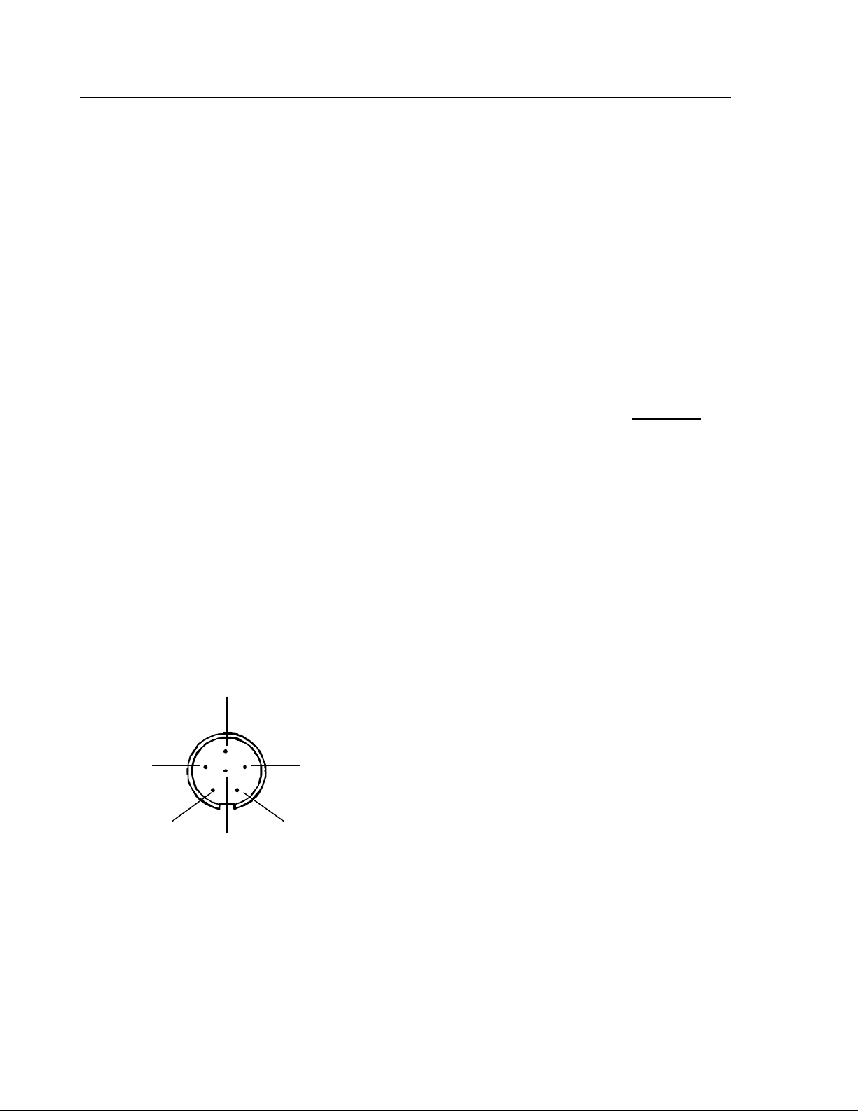
For connecting scanner TK5, a 6 pin socket to DIN 45322 is fitted on the control unit front panel.
3
2
1
5
6
45
Note:
Using a different scanner may damage and/or destroy
4
scanner and control unit.
BK MIKRO 5-RL Page 5
Page 7
System Components
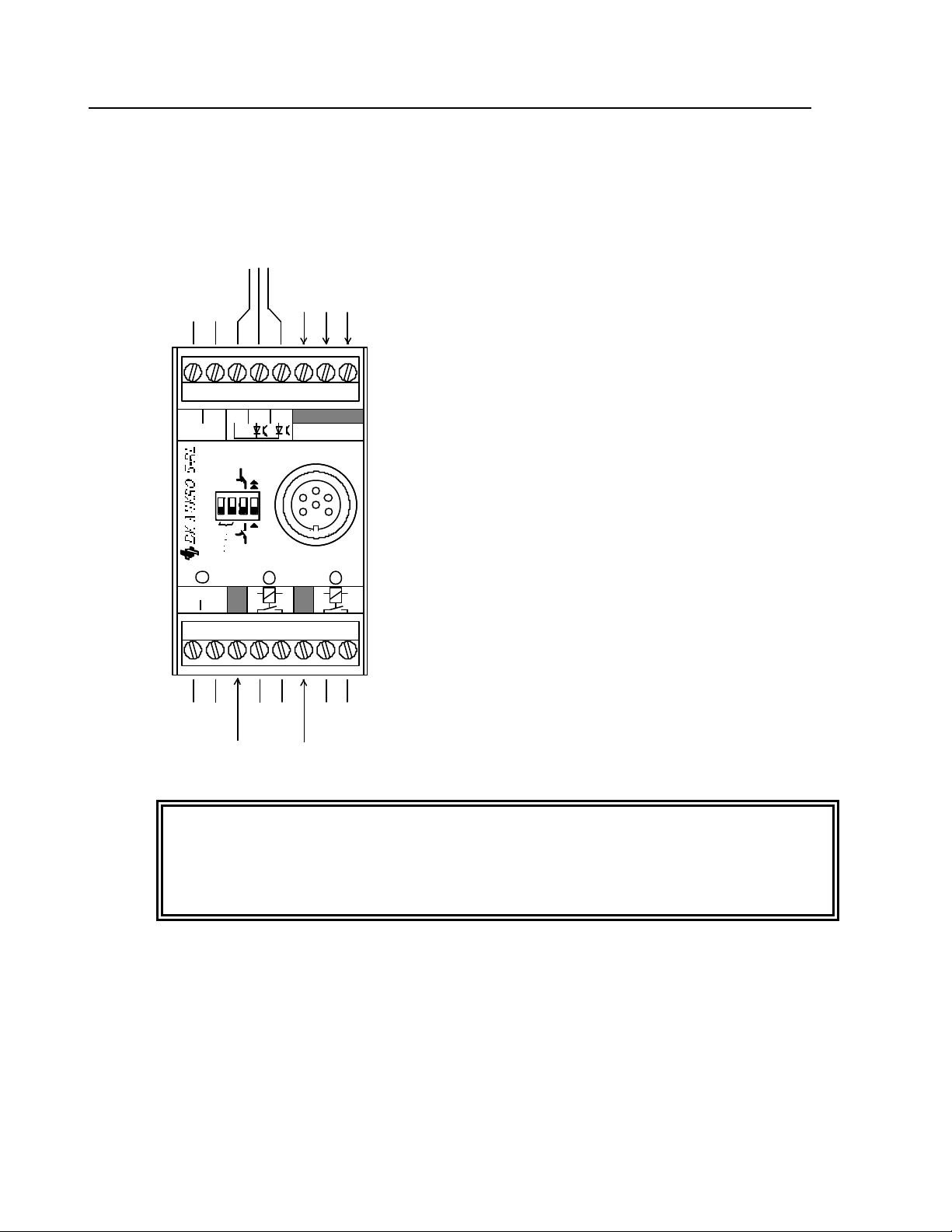
2.1.4. Screw Terminals
The screw terminals have been arranged on two plug-in terminal blocks. These blocks are keyed so
that they cannot be accidentally plugged into the wrong socket. When in operation, plastic caps
cover the screws in the front. Wires to be connected are routed from the top or bottom of the unit.
Power supply, control inputs, relay outputs, and the scanner are all connected via these screw
terminals.
Control Inputs
Power
Supply
DC 24 V
+ –
DC 24 V
Com LernStart
1 2
These Terminals
must not be wired up!
Scanner
o.k.
"o.k."-
Relay
AC 230 V
L1 N
Power
Supply
e.g. AC 230 V
k.o.
"k.o."-
Relay
These terminals must not be wired up !
Note:
These plugs may only be inserted or removed when the power supply has been
disconnected.
Unmarked terminals must not be connected.
Page 6 BK MIKRO 5-RL
Page 8

System Components
2.1.4.1. Power Supply
"24 VDC" Model
• Terminal "+" 24 VDC
Supply Voltage Input 24 VDC ± 20%
Input Current 0.25 A max .
• Terminal "–" 24 VDC
Reference potential of 24 VDC supply voltage.
"120 VAC" and "230 VAC" Models
Depending on the specific model, the unit will be supplied preconfigured for "120 VAC" or
"230 VAC". The relevant version will be marked on the unit type plate next to the supply connections
on the front panel.
• Terminals "L1" and “N”
Supply Voltage Input, depending on model:
120 VAC (I
230 VAC (I
• Terminal "+" 24 VDC
= 0.05 A) or
max
= 0.025 A)
max
Control voltage output for controlling inputs "Start" and "Learn,” 24 VDC (16 V ... 32 V) unregulated.
The control voltage meets the requirements for an extra low function potential with safe
disconnection.
Output Current 0.1 A max.
If an external control voltage is applied, this terminal is not connected.
• Terminal "–" 24 VDC
When using the internal control voltage, this terminal must be connected to the control inputs
terminal "Com".
If an external control voltage is applied, this terminal is not connected.
Note:
Alternatively, "120 VAC" and "230 VAC" models may also be supplied with 24 VDC. In this case,
terminals "L1" and "N" must not be connected. Terminals "+24 V" and "–24 V" are to be connected
as described above for "24 VDC" model.
BK MIKRO 5-RL Page 7
Page 9
System Components
2.1.4.2. Control Inputs
• "Com" Terminal
Reference potential for control inputs
• "Start" Terminal
An input level of +24 VDC will trigger a "sensing" cycle.
The input current is approximately 5 mA; pulses lasting less than 6 ms will be disregarded.
• "Lern" Terminal
An input level of +24 VDC will trigger a "learning" cycle (the "teach-in").
The input current is approximately 5 mA; pulses lasting less than 6 ms will be disregarded.
The position stored during the learning cycle will remain stored even after the unit has been
switched off. Therefore, a new "teach-in" session is required only when your tool geometry
changes, or the scanner is changed.
2.1.4.3. Relay Outputs
The terminals have been designed as dry relay contacts. By switch selection, they may be configured
as either normally open or normally closed. (Note that when using the relays as normally closed, the
contacts will be open when there is no power to the unit.) The contacts have been designed for 250 V
and protected against inductive switch-off peaks of up to 19 W (2 ms).
Maximum switching power is 500 VA.
Maximum switching current may not exceed 2 A.
• "K.O." Relay Terminals
These two terminals are used to indicate a fault message (K.O.).
• "O.K." Relay Terminals
These two terminals are used to indicate a good cycle (O.K.).
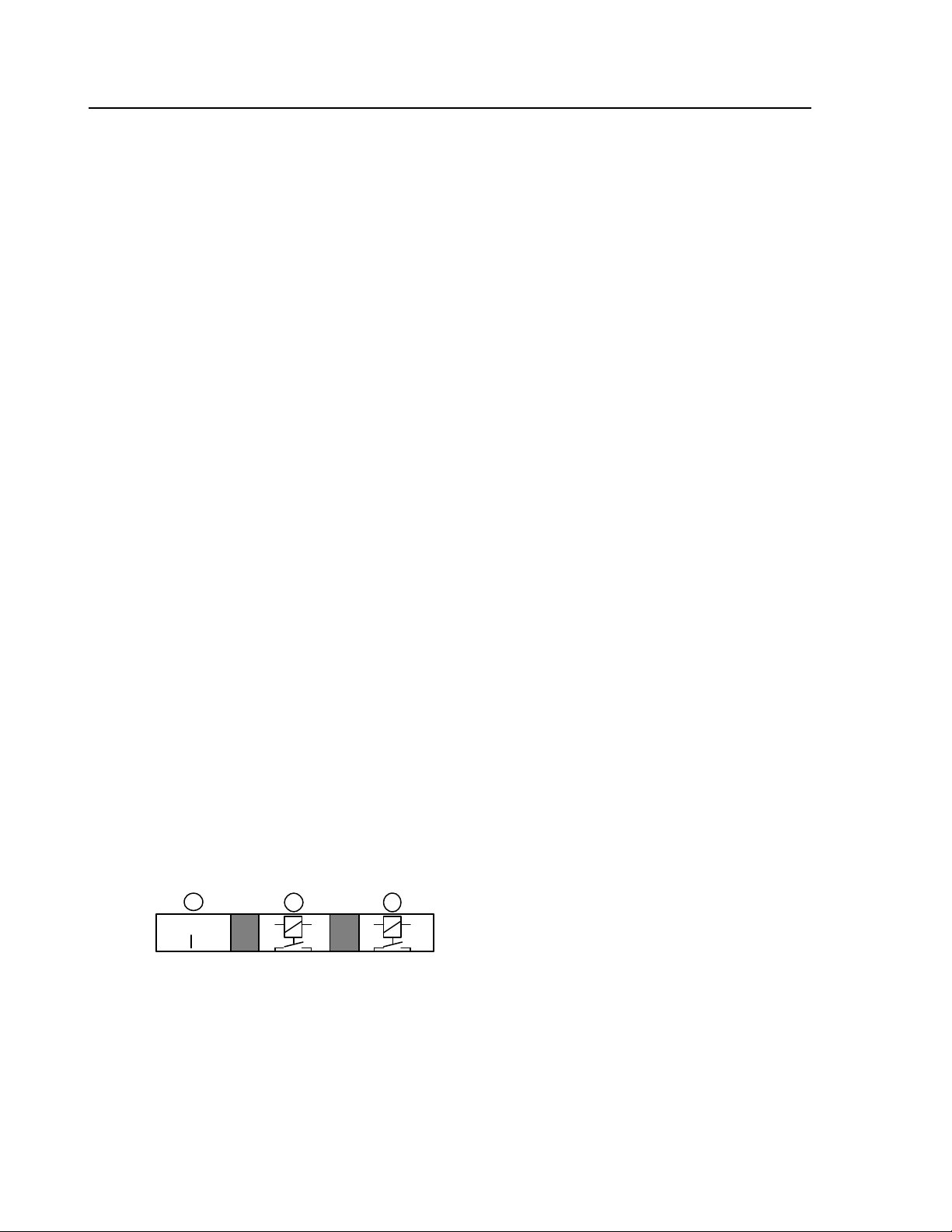
2.1.5. Light-Emitting Diodes
Three light -emitting diodes on the front panel inform users about the current status of their BK MIKRO
5-RL monitoring system:
AC 230 V
L1 N
o.k.k.o.
• Power Supply / Status
yellow LED to indicate supply voltage or status
• "K.O." Relay
red LED to indicate fault message
• "O.K." Relay
green LED to indicate no fault message
Page 8 BK MIKRO 5-RL
Page 10
System Components
Normally Open Contact
Normally Closed Contact
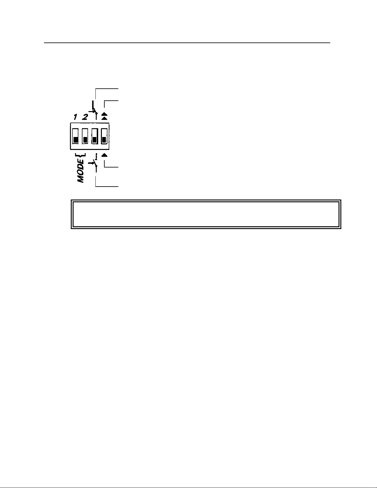
2.1.6. Toggle Switches
Using the four toggle switches arranged next to each other on the control unit front panel, the following
functions may be set.
Relay as
Cancel Decel
Normal Decel
Relay as
Note - Setup on Delivery:
All switches are toggled downwards.
2.1.6.1. Switch "MODE 1"
The “MODE 1” switch determines how the home position is located. With the switch in the “off” or
“down” position, the unit will automatically set the home position as being halfway between the two
tool positions. If the switch is in the “on” or “up” position, the unit will use the position that the wand
is in when the learn cycle is initiated as its home position.
2.1.6.2. Switch "MODE 2"
The switch “MODE 2” has been reserved for future new features, and does not have any function at
this time.
2.1.6.3. "Normally Open Contact/Normally Closed Contact" Switch
The "Normally Open Contact/Normally Closed Contact" switch determines the mode of operation for
the two output relays.
2.1.6.4. "Decel" Switch
BK MIKRO 5-RL Page 9
The "Decel" switch determines whether the scanner will slow down while in its scanning range.
Note:
For normal tool detection applications, this switch should be in the “Normal Decel” position, as the
normal deceleration of the unit is designed to protect the unit from wear and tear.
Page 11

System Components
2.1.7. Notes on Technical Safety
The control unit comprises the following circuits, all isolated from each other:
K.O. Output (2 terminals) safely isolated from all other circuits
O.K. Output (2 terminals) safely isolated from all other circuits
AC power supply (L1, N) safely isolated from all other circuits
DC power supply safely isolated from K.O. output, O.K. output,
(+24 V, –24 V and AC power supply
simply isolated from control inputs
no isolation from scanner connections
Control Inputs safely isolated from K.O. output, O.K. output,
(Com, Start, Lern) and AC power supply
simply isolated from DC power supply and
scanner connections
Scanner Connections safely isolated from K.O. output, O.K. output,
and AC power supply
simply isolated from control inputs
no isolation from DC power supply
Page 10 BK MIKRO 5-RL
Page 12
System Components
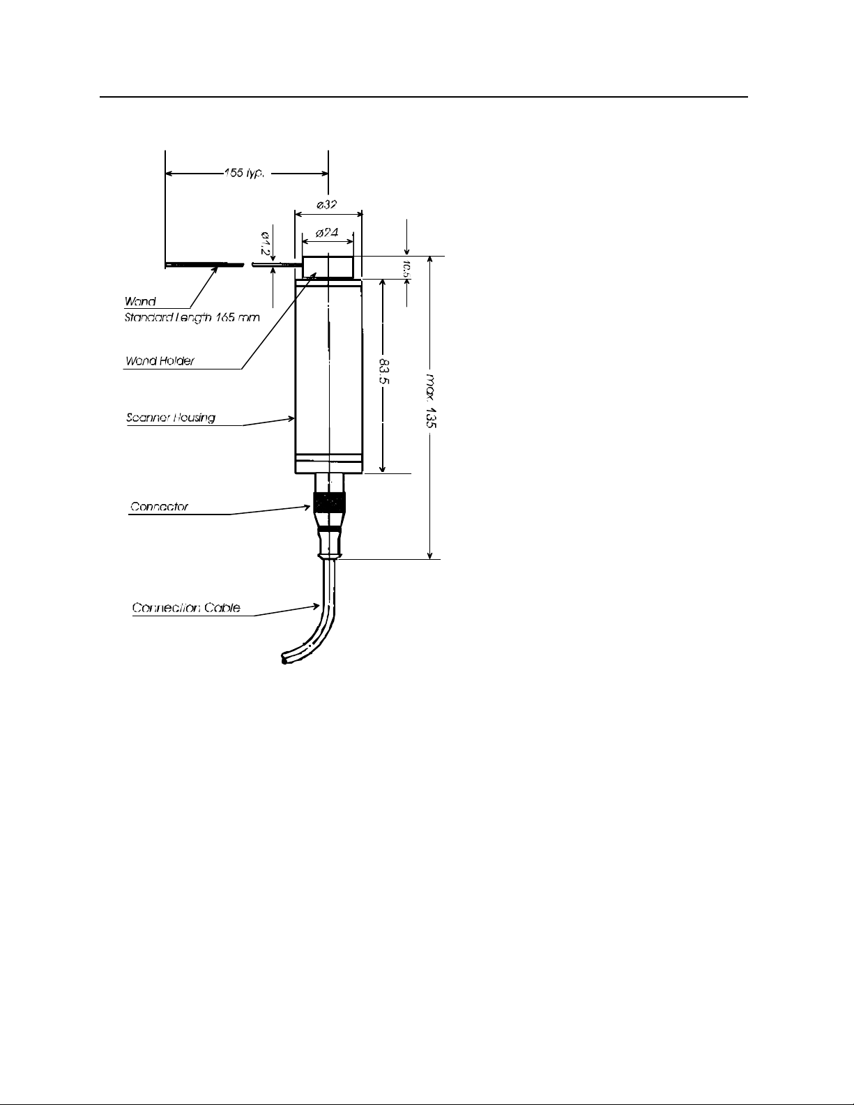
2.2. Scanner TK 5
Note: A right angle cable connector
is available for applications with
limited clearance behind the
scanner.
2.2.1. Characteristic Properties
The scanner housing is cylindrical and smooth, thus permitting easy installation, e.g. using a collet
chuck. The scanner is designed for easy access for servicing and changing the wand.
Aligning the scanner is easy and requires no additional instruments or aids. The wand is to be
positioned at random between the two objects to be monitored. Its "teach-in" cycle will determine the
respective positions of these objects, calculate zero position as the center between the two tools and
move the wand into this position.
Note:
Using scanner TK 5 with a different control unit than BK MIKRO 5-RL may damage and/or destroy
scanner and control unit.
Your wand is a wearing part!
BK MIKRO 5-RL Page 11
Page 13
System Components
br
Each contact with a rotating object will cause corresponding wear on the wand. This may even lead to
the metal wand breaking. Due to the injury hazard this causes, users should exercise particular
caution within any BK MIKRO 5-RL rotating area.
2.2.2. Technical Data
Housing........................................ Anodized Aluminum
Protection Type............................. IP 67
Wand Length ................................165 mm (standard)
Scanning Angle............................. ± 180°
Control Unit Connection................. Connector, M12x1, 6 pins
Temperature Range....................... 0°C to +80°C
Sensing Cycles .............................> 10 million with normal decel
Option: Wand Holder for Small Chips
If BK MIKRO 5 is used to monitor manufacturing processes where materials with small chips are
processed (e.g. cast iron, diecast aluminum, brass), we recommend the use of our specially designed
wand holder for this purpose.
2.3. Connection Cable
Control unit and scanner are connected by a 6-wire PUR-cable:
• connector to DIN 45322 at the control unit end
• molded plug at the scanner end
• length 5 m, can be extended to a maximum length of approximately 25 m.
Pin Configuration (at the control unit end)
3 gn
1 wh white
2 br brown
4
ye
2
3 gn green
4 ye yellow
5
gr
6 pi
1
wh
5 gr gray
6 pi pink
If this plug needs to be removed during fitting, please ensure that this pin configuration is followed on
reassembly.
Note:
To avoid unnecessarily reducing the operational life of this cable, it should not be subject to more than
a minimum amount of movement during operating cycles.
Page 12 BK MIKRO 5-RL
Page 14

Function
3. Function
3.1. Teach-in
The "teach-in" cycle will be started by an active input signal on the "Learn" terminal. Both relay
outputs for "O.K." and "K.O." will become inactive. The wand will first travel in clockwise direction.
If a tool is detected, its position will be stored. The wand will then travel in counter-clockwise
direction to determine the position of the second tool. The position of this second tool will also be
stored.
• Using both positions, the system will calculate the new zero position for the wand, which is the
mathematical center of the two learned positions (if switch “MODE 1” is down), or the location of the
wand at the beginning of the teach-in cycle (if switch “MODE 1” is up). Finally, the wand will move
into its newly calculated zero position. In addition, the "O.K." relay will be activated and indicated on
the "O.K." LED.
• In the event of a faulty learning action, the "K.O." relay will activate, the "K.O." LED lights up. The
wand will return into its old position. Subsequent starts will be ignored.
Note:
A position learned during "teach-in" will remain stored, even after removal of power to
the unit.
Ensure that tool geometry (layout and dimensions) at "teach-in" corresponds to the
geometry used during monitoring in the "Start" mode.
3.2. Start
A "Start" cycle will be triggered by an active input signal on the "Start" terminal. Both relay outputs for
"O.K." and "K.O." will become inactive.
The wand will travel to the previously "learned" positions of the objects to check for their presence. In
so doing, the wand will first travel in a clockwise direction.
• If both tools are in their "correct" positions, the "O.K." relay will be activated. Angle tolerance for a
no fault message (O.K.) is +10° in relation to the learned position.
• If one of the two tools is not detected, i.e. either it is missing or there is an obstacle within the wand
rotating area, the "K.O." relay will be activated.
In addition, the light -emitting diodes on the control unit will indicate the result.
BK MIKRO 5-RL Page 13
Page 15

Function
3.3. Scanning Times
Depending on the length of the path to be traveled, different scanning times will result. Several test
series produced the following typical results:
Angle Measuring Time Scanning Time
± 15° 300 ms 300 ms
± 180° 1200 ms 1200 ms
This shows: Scanning time = measuring time
3.4. Status Indication
3.4.1. Yellow LED
Fast Flashing = Self-Test
After power-up, the system will carry out a self-test indicated by fast flashing of this yellow LED.
Steady Illumina tion = Ready to Operate
Following its self-test, the system is ready to operate. The LED stops flashing and remains steady.
Slow Flashing = Motor Fault / Cable Break
The system has detected a motor fault or cable break. Outputs will be switched inactive, the unit will
remain in its present state, indicated by slow flashing of this yellow LED.
3.4.2. Red/Green LED
Steady Illumination = Indication following Scanning Cycle
The red LED indicates a fault message.
The green LED indicates a no fault message.
3.5. Deflection of Wand
Rotation angles will be detected by scanner encoder pulses. These pulses are derived from the
rotation of the motor. For scanning, a metal needle (wand) is used which, depending on the scanning
force, can be deflec ted. As the scanner motor is still turning when the end of this wand has already
come to a stop, differences between the set and actual rotation ranges will result.
For all speeds, wand deflection is compensated to a range of less than 10°. Deflection will depend,
however, on wand length.
Page 14 BK MIKRO 5-RL
Page 16
Installation Notes
4. Installation Notes
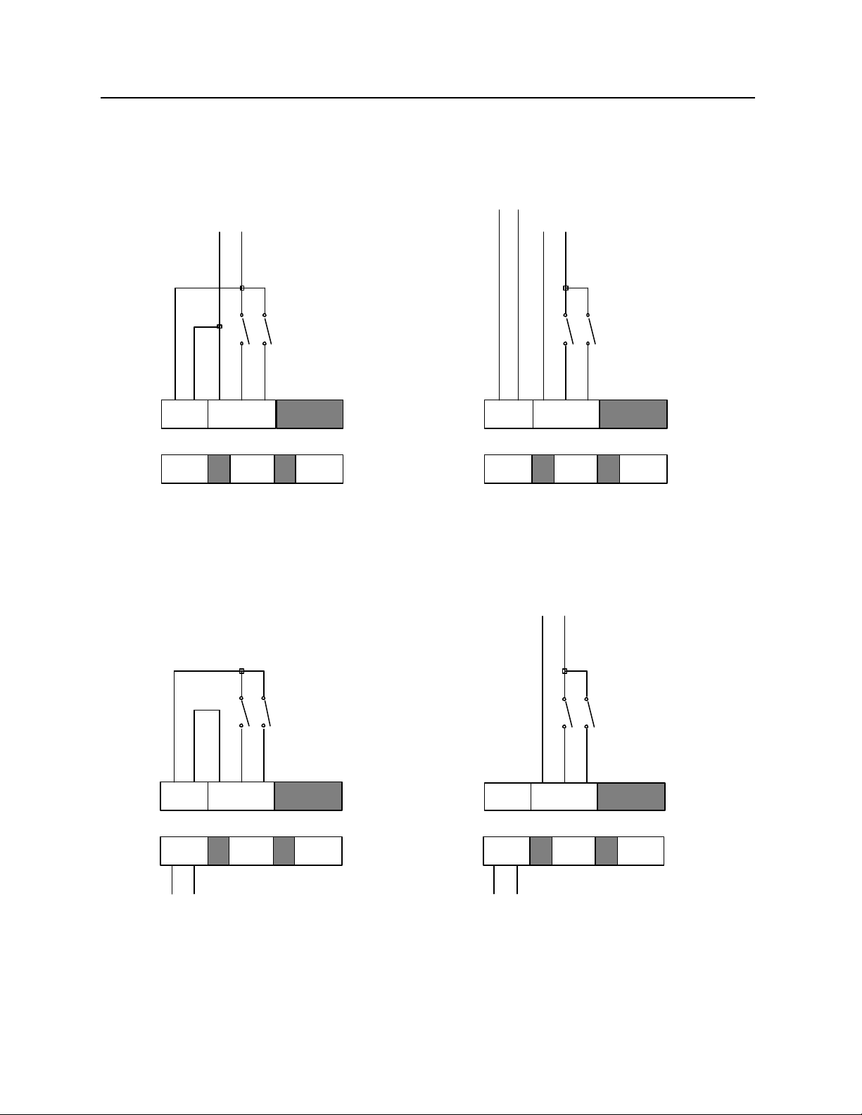
4.1. Control Voltage Connection
Power Supply
Control Voltage
GND DC 24 V
Power Supply
GND24 V
Control Voltage
GND DC 24 V
Start Learn
+ –
DC 24 V
Com Start Lern
k.o.
C NO/NC
o.k.
C NO/NC
BK MIKRO 5-RL
DC 24 V
common power and control voltage supply
Start Learn
Start
+ –
Com Start Lern
DC 24 V
k.o.
C NO/NC
BK MIKRO 5-RL
DC 24 V
separate control voltage
Control Voltage
ext.
ext.
GND
DC 24 V
Start Learn
Learn
o.k.
C NO/NC
+ –
Com Start Lern
DC 24 V
AC 120 V
AC 230 V
L1 N
Power Supply
k.o.
C NO/NC
BK MIKRO 5-RL
AC 230 V (AC 120 V)
internal control voltage
o.k.
C NO/NC
+ –
DC 24 V
AC 120 V
AC 230 V
Power Supply
L1 N
Com Start Lern
k.o.
C NO/NC
BK MIKRO 5-RL
AC 230 V (AC 120 V)
external control voltage
o.k.
C NO/NC
BK MIKRO 5-RL Page 15
Page 17

Installation Notes
4.2. Electrical Interference Prevention
All inputs are opto-decoupled and thus maximally protected against interference voltage peaks, as
caused, for example, by inductive sources.
Relay outputs are protected by varistors against inductive interference voltage peaks. Depending on
the type of load used, further interference suppression measures may be necessary.
To ensure optimum operational safety, suppression measures, if required, must be taken at the
source, i.e. directly where interference is caused.
Possible additional noise filters:
• RC combination (included in the contactor suppliers' product ranges)
• Varistors
• Diodes
Appendix A
Model 5 Manufacturing and Techna -Tool Part Numbers
COMPLETE SYSTEMS:
BK5 110 AC Volt System BK5110S
(Includes BK5SC, BK5110, BK5C5 and BKMB)
BK5 24 DC Volt System BK524S
(Includes BK5SC, BK524, BK5C5 and BKMB)
COMPONENTS:
Model # Description
Scanner: BK5SC Scanner (TK5K.xx)
Controller: BK5110 110 Volt AC (8.0502.xx, 6304202)
Note: BK5110 works with 110 or 24V
BK524 24 Volt AC (8.0503.xx, 6304207)
Cable: BK5C5 5 meter length
Bracket: BKMB Mounting Bracket
50mm sq. (2" Square)
ACCESSORIES
Cables: BK5C5R 5 meter length w/ rt. angle
**BK5C10 10 meter length cable
**BK5C15 15 meter length cable
**BK5C20 20 meter length cable
** Right angle connectors are available.
Extension Cables - (must be used with cable BK5C5 or BK5C5R above)
BK5EC5 5 meter length
BK5EC10 10 meter length
BK5EC15 15 meter length
Mounting Bracket: BKMB 50 mm sq. (2 inch sq.)
Delivery: 1-5 systems normally from stock / 6 or more 2-4 weeks
Page 16 BK MIKRO 5-RL
 Loading...