

Page 1
FM TRANSMITTER
Page 2

Introduction
You’ve already unpacked it, haven’t you? You’ve unpacked it and plugged it in
and turned it on and fiddled with the knobs. No? Okay, good. Please take a few
minutes to read the manual and familiarize yourself with your new Technalogix
FM power amplifier or transmitter.
We believe that this user manual, the Quickstart package (Final Inspection
Report, Wiring Hookup, and Block Diagram), and of course our equipment,
should be everything you need to get on the air with a superb audio signal. We
understand that a capable and confident user will get the most out of our product
and we have made every attempt to educate readers of all technical levels. If
there is something that is not clear, or you require further information, please do
not hesitate to contact us and we’ll be glad to help out.
Technalogix Ltd.
#4, 8021 Edgar Industrial Place
Red Deer, Alberta, Canada
T4P 3R3
Phone: 403.347.5400
Fax: 403.347.7444
URL: www.technalogix.ca
Email: [email protected]
All information that is specific to your unit is contained within the Quickstart
package (Final Inspection Report, Wiring Hookup, and Block Diagram) included
in the shipped equipment container. This Quickstart package summarizes
performance specifications, provides wiring hookup details, and outlines specific
components found in the system.
We truly appreciate that you have chosen us as your RF equipment supplier.
Happy transmission!
Last Revised:
14-Mar-2014
Page 3

General Safeguards
This section is written as a general guide to keep all five fingers on your hand
and is intended for those having previous knowledge and experience with these
kinds of equipment. It is not intended to contain a complete statement of all
safety precautions, which should be observed by personnel using this or other
electronic equipment.
Documentation
Read, retain and follow instructions before operating the equipment. There is a
lot of useful information in the manual, and besides, we spent a lot of time writing
it!
Environment
To reduce the risk of fire or electric shock, do not expose this equipment to rain,
moisture, or rye and sodas at the company Christmas party. Refer all servicing to
qualified service personnel.
Servicing
Do not attempt to service this equipment yourself as opening or removing covers
can result in a warm tingly feeling and will void the warranty. Refer all servicing
to qualified service personnel.
1
2
3
4
5
6
Safeguards
Warranty
Terms and
Operation
Principle of
Installation
Operation
Control System
7
RF Components
8
Power Supply
9
Maintenance
10
Troubleshooting
Page 4

Safety and First Aid
Personnel engaged in the installation, operation, maintenance, or servicing of
electronic equipment are exposed to the hazard of high voltage. It is imperative
that all safety regulations and precautions are consistently observed. Knowledge
of first aid procedures is recommended. The following information is presented
as a reference only. The user should ensure that they are trained in proper first
aid and the necessary precautions, which may not be contained in this manual,
are followed.
At all times, avoid placing any part of the body in series between ground and
circuit points, whether power is on or off.
Dangerous voltage may be present in equipment even though power is off.
Do not open the cabinet. Refer servicing to qualified service personnel.
It is the duty of all personnel to be prepared to give adequate emergency first
aid treatment and thereby prevent avoidable loss of life.
There are three principle degrees of burns, recognizable as follows:
a first-degree burn reddens the skin.
a second-degree burn blisters the skin.
a third degree burn chars the flesh and frequently places the victim in a
state of shock accompanied by respiratory paralysis.
Respiratory paralysis can cause death by suffocation within seconds. It is
imperative that the approved methods of artificial respiration are initiated
immediately and continue until the victim’s breathing is normal.
A muscular spasm of unconsciousness may render the victim unable to break
free of the electric power. If this is the case, turn the power off immediately.
Do not touch the victim or you may share the same predicament!
If the power cannot be turned off immediately, very carefully loop a dry rope,
article of clothing, length of strong cloth or a rolled-up newspaper around the
victim and pull the victim free of the power source. Carefully avoid touching
the victim or clothing.
Once free of the power source, the victim must be placed in a reclining
position and covered with a blanket or newspapers to keep warm. At the first
opportunity, enlist help in summoning a doctor. If a doctor cannot be
summoned, transport the victim to the doctor or a hospital. Be sure the victim
is kept well covered and warm while awaiting professional treatment.
1
2
3
4
5
6
7
8
9
10
Safeguards
Warranty
Terms and
Operation
Principle of
Installation
Operation
Control System
RF Components
Power Supply
Maintenance
Troubleshooting
Page 5

Operating Safeguards
Load Impedance
It is a known fact that our FM equipment enjoys 50-ohm load impedances. So
much so, that it is imperative you maintain 50-ohm impedances throughout your
system. In return, your equipment will provide you with maximum power transfer
to the antenna and decreased reflected power heading back towards the
amplifier pallets, reducing the amount of magic smoke that gets let out of the
equipment. Before anything is turned on, ensure that there is a 50-ohm path from
the output of each stage to the input of the next, all the way to the antenna.
Operating Warnings
Our FM equipment is designed to reliably generate a specific RF output power
level. Failing to adhere to overdriven amplifier, high reflected power, and high
temperature, and other warnings can decrease the reliability of your system, and
frankly, makes our repair department busy and grumpy. If you need to transmit to
a little larger coverage, you are better off increasing antenna gain, and more
importantly, antenna height above average terrain. On FM broadcast
frequencies, insufficient antenna height puts an upper limit on your range,
regardless of power levels, as the distance from your antenna to the radio
horizon is limited.
1
2
3
4
5
6
Safeguards
Warranty
Terms and
Operation
Principle of
Installation
Operation
7
8
9
10
Control System
RF Components
Power Supply
Maintenance
Troubleshooting
Page 6

Terms of Sale
Sales by Technalogix Ltd. (“Seller”) are made only on terms which are contained
in this policy. Seller hereby gives notice of its objection to any different/additional
terms and conditions. All sales are expressly conditional upon Buyers’ assent to
the terms and conditions set forth below. These terms and conditions may be
modified/ supplemented only by written document signed by authorized
representative of the Seller. These terms and conditions supersede any prior
and/or contemporaneous agreements/correspondence between Buyer and
Seller. Any order received and accepted by Seller shall be construed as
acceptance of Seller’s offer to sell its products to the Buyer in accordance with
terms and conditions of sale set forth herein. No waiver, whether express or
implied, by Seller of any of the terms or conditions hereof shall be deemed a
continuing waiver or trade custom between parties, but shall apply solely to the
instance to which the waiver is directed.
Ordering Information
All orders must be in writing and/or accompanied by a Purchase Order. A
minimum down payment is required with all orders. No orders are considered an
order until the payment has been made.
Pricing Policy
All prices are FOB shipping point and prices do not include freight, handling, and
insurance. All prices published/quoted by Seller may be changed at any time
without notice. Unless otherwise specified, written quotations expire 30 days from
date issued and subject to change/termination by notice during this period.
Taxes
Prices for all products do not include any sales, use, excise or other taxes. Buyer
agrees to pay all applicable taxes, duties and other fees on product and services
ordered. If Buyer claims an exemption from any tax, Buyer shall submit to Seller
the appropriate exemption certificates.
Shipping
Shipping is the responsibility of the Buyer. This includes all freight, customs and
brokerage charges, duties, and insurance.
1
2
3
4
5
6
7
8
9
10
Safeguards
Warranty
Terms and
Operation
Principle of
Installation
Operation
Control System
RF Components
Power Supply
Maintenance
Troubleshooting
Page 7

Terms of Payment
Seller will provide credit terms to Buyer at its discretion. Such terms are subject
to change at all times. If credit is provided, Seller will invoice Buyer on the date
the product is ordered. Such invoices will be due and payable net thirty (30) days
from the date of invoice, subject to credit is not established or maintained, terms
shall be net cash on or prior to the Delivery Date. Seller reserves the right, at its
sole discretion at any time to revoke any credit previously extended. Past due
accounts shall be charged two percent (2%) per month, or the highest rate
permitted by Alberta law, whichever is less, and will be added to the outstanding
balance. In the event Buyer defaults on the payment, Buyer shall be liable for all
collection costs, including reasonable attorney’s fees and costs. Non-payment of
past due accounts will result in a lien against parts and all subsequent
assemblies or products that our components are in. Goods remain the property of
Seller until invoice is paid in full.
Changes and Cancellation
Purchase orders that have been accepted by Seller may not be changed/
cancelled, in whole or part, without written Seller consent. All changes must be
included in change order reflecting purchase order and submitted to the Seller.
All other changes will not be accepted/acknowledged. Changes may affect
delivery dates. Expenses incurred because of changes shall be charged to
Buyer. Buyer will be liable for Seller’s costs incurred, plus a reasonable profit, for
the portion of work terminated, in accordance with generally accepted accounting
principles, together with cancellation charges. Orders for standard product may
be changed by Buyer, with no penalty to Buyer, provided that Buyer provides
Seller notification at least 30 days prior to scheduled ship date. Order changes
received within 30 days of scheduled ship date may be subject to an order
change charge; a schedule detailing these charges will be forwarded to Buyer
when Buyer’s change order is acknowledged. In no event can any aspect of the
order be changed after the product shipment has occurred. Custom orders may
be cancelled by Buyer, provided that Buyer pays Seller for completed work
allocated to Buyer’s order at time of termination of the work at selling price and all
costs for work-in-progress and costs resulting from cancellation and reasonable
profit therein. Specific cancellation charges dependent on the type of custom
product ordered. A schedule detailing these charges will be forwarded to Buyer
when Buyer’s cancellation fee of up to 100% of the order, depending on the
stage of completion of the order at the date the cancellation or revised is
accepted.
1
2
3
4
5
6
7
8
9
Safeguards
Warranty
Terms and
Operation
Principle of
Installation
Operation
Control System
RF Components
Power Supply
Maintenance
10
Troubleshooting
Page 8

Custom Products Policy
Custom items are not returnable. Items other than “off the shelf” products are
considered custom and are products/materials which have been altered,
1
Safeguards
amended and customized to your order, and not resalable.
Returns
2
Warranty
Terms and
Product return without written authorization by Seller will not be accepted.
Returns accepted only with a valid Return Material Authorization (RMA). To
receive authorization for product return, call Seller. There is a standard 25%
restocking cost assessed on most returns. All returned products (non-repair)
3
Operation
Principle of
must be unused, and in original condition. No refund/credit given for damaged
products. We do not accept postage-due/ C.O.D. packages at any time.
Excusable Delay
4
Installation
Seller shall not be liable for any loss or damage resulting from any delay in
delivery or failure to deliver which is due to any cause beyond Seller’s control,
including, without limitation, acts of nature, unavailability of supplies or sources of
5
Operation
energy, riots, wars, fires, floods, epidemics, lockouts, strikes and slowdowns,
delays in delivery by supplies, or acts or omissions of the Buyer. The Buyer shall
be liable for stage charges, including but not limited to all third party costs and
expenses incurred by Seller, in holding or storing products for the Buyer or at the
Buyer’s request.
6
Control System
Assignment
7
Buyer shall not assign any duties nor assign any order or any interest therein
RF Components
without written consent of the Seller. Any such actual or attempted assignment
shall entitle Seller to cancel the order upon written notice to the Buyer.
Installation
8
Power Supply
Seller assumes no obligation to install any product sold to place any products in
working order at Buyer’s premises and not responsible for freight damage.
9
Maintenance
Validity of Separate Clauses
10
If any provisions of this agreement shall be held invalid, illegal, or unenforceable,
the validity, legality or enforceability of the remaining provisions shall not be
Troubleshooting
affected or impaired thereby.
Page 9

Warranty
Technalogix products have been completely tested and found to meet
specifications and be in proper operating condition. Technalogix-manufactured
products are warranted to be free from defects in materials and workmanship for
a period of two years from the date of shipment. Products sold through, but not
directly manufactured by Technalogix, carry the original manufacturer’s warranty.
Seller will not be liable for damages of whatever nature arising out of or in
connection with the equipment or its use thereof. Technalogix does not assume
responsibility for injury or damage resulting from the practices of untrained or
unqualified personnel in the handling of this equipment and does not include
misuse, neglect or accident, incorrect wiring and/or improper installation,
unauthorized repairs, modifications or use in violation of instructions issued by
Seller, incidental or consequential damages as a result of any defect, reshipment
cost or insurance of the unit or replacement units or parts, acts of nature,
damages due to AC or DC power supplied by customer to power the equipment
(see installation recommendation for surge protection), or acts of terrorism. Seller
agrees, at our option, to remedy warranted defects or furnish a new part in
exchange for any part of unit which, under normal installation, use and service,
becomes defective. The user pays for transportation costs to and from repair
facility. If you require on-site service, the cost to you will be $800.00 US per 8hour day plus air fare, meals, and transportation charges for personnel and
equipment.
1
2
3
4
5
Safeguards
Warranty
Terms and
Operation
Principle of
Installation
Operation
6
7
8
9
10
Control System
RF Components
Power Supply
Maintenance
Troubleshooting
Page 10

Principle of Operation
The internal FM exciter found inside FM transmitter enclosures accepts analog,
digital or MPX audio signals and modulates them onto an FM carrier. The analog
signal can be either mono or stereo (both included as standard), while the digital
inputs are accepted on AES3, S/PDIF optical (Toslink), or S/PDIF coaxial inputs.
Also included on the Exciter circuit board are amplifier stages to increase the
modulated level from a few dBm up to several watts.
The RF power amplifier is designed to take a modulated FM carrier from the
Exciter (typically less than 30-watts depending on transmitter power level), and
amplifies the carrier to a level that is suitable for transmission through an
antenna, cavity, or alternative load. The power amplifier feeds this load through
an inline wattmeter and transmission line. For broadcast and over-the-air
amplifier systems, the pattern of the antenna then dictates the range and
coverage area.
The amplification is accomplished by one or many amplifier pallets internal to the
power amplifier system. If there is more than one amplifier pallet stage, then the
first pallet acts as a driver feeding Intermediate Power Amplifiers (IPAs) and/or
final stage pallets. If multiple final pallets are required, then a splitter and
combiner are also required before and after the final stages.
Technalogix manufactures FM amplifiers and transmission systems suitable for
88.0 to 108.0 MHz. Custom frequencies are available upon request if you require
carriers outside this range, including audio for VHF applications and other unique
requirements.
The RF amplifiers utilize readily available RF components wherever possible,
thus enhancing the serviceability of the equipment. The amplifier modules are
stable for high reliability and long service life and feature ultra linear amplification
and individual channel RF output filtering, unless ordered otherwise.
The Block Diagram is included with the Quickstart package to illustrate the
specific component flow of the RF amplifier system and to provide specific
configuration and model information.
1
2
3
4
5
6
7
8
Safeguards
Warranty
Terms and
Operation
Principle of
Installation
Operation
Control System
RF Components
Power Supply
9
Maintenance
10
Troubleshooting
Page 11

Installation
This section contains installation recommendations, unpacking, inspection, and
installation instructions for the power amplifier or transmitter. We are sure that
you are chomping at the bit to install your new system, so we recommend that
you read the following sections very carefully.
Building Recommendations
The quality of the building is of great importance if you are to expect long life and
continued performance from the power amplifier or transmitter. The building must
be clean, dry, temperature controlled and secure. Don’t forget to allow space in
the building for any additional racks to house test equipment, a workbench area,
line regulating transformers, ladders, equipment and parts storage, first aid kit,
emergency generator if used, as well as heating and cooling devices that may be
unique to your installation. A beer fridge is optional. A sloping roof will tend to
develop leaks less rapidly. The building should be well roofed with good material.
The cooling load will be lowered with reflective or light colored roofing material.
Electrical Service Recommendations
Technalogix recommends that a qualified, licensed local electrician be consulted
for the required electrical service. We suggest local electricians because:
The personnel knows the local codes
The personnel can be on site readily
You are apt to get better overall support if you give what business you can
to local suppliers
Technalogix recommends that proper AC line conditioning and surge
suppression be provided on the primary AC input to the power amplifier or
transmitter. If DC is used as a source, a DC-DC converter is recommended to
provide isolation between the supply and the load. All electrical service should
be installed with your national electrical code in your area, any applicable
provincial or state codes, and good engineering practice. Special consideration
should be given to lightning protection of all systems in view of the vulnerability of
many sites to lightning. Lightning arrestors are recommended in the service
entrance. Gas Discharge Tubes (GDT) may help in preventing lightning, which
was forecast for another day, from creating a bad day. Straight and short grounds
are recommended. The electrical serviced must be well grounded. Do not
connect the unit to an open delta primary power supply, as voltage fluctuations
could harm the unit. Branch your circuits. Do not allow your lights, your
workbench plugs, and your transmitting or translating equipment to operate on
one circuit breaker. Each amplifier or transmitter should have its own circuit
breaker, so a failure in one does not shut off the whole installation.
1
2
3
4
5
6
7
8
9
10
Safeguards
Warranty
Terms and
Operation
Principle of
Installation
Operation
Control System
RF Components
Power Supply
Maintenance
Troubleshooting
Page 12

Antenna and Tower Recommendations (if applicable)
Your preliminary engineering workgroup should establish your antenna and tower
requirements, if applicable, both for receiving and transmitting antennas.
Construction of sturdy, high quality antenna/tower systems will pay off in terms of
coverage of your service area, the overall quality and saleability of your radiated
signal, and reduced maintenance expenses. Technalogix provides complete
turnkey antenna systems if needed. If your site is serving as a translator, your
receiving antenna should be in line of sight to the originating station all year
round. The foliage will change with season. Transmitting antennas can enhance
or seriously impair the amplifier or transmitter output.
The selection, routing, and length of coaxial cable are extremely important in the
installation. If there is a 3 dB line loss in the cable between your unit’s output and
the transmitting antenna, the unit will only deliver half power. Buy the best cable
you can obtain, route it via the shortest way to the antenna, and keep it straight.
Do not form it into sharp bends on its way. Do not use any more cable fittings for
the installation than absolutely necessary. All cautions here apply equally to all
coaxial cables in the system - input and output.
Pay attention to radial ice accumulation when designing the transmission system.
It is not uncommon for at least an inch of ice to build up on a tower or antenna in
some locations. This in turn significantly increases the weight, cross section, and
wind loading of the system, not to mention creating issues from reflective power.
Attaching the transmission line to the tower is crucial to maintain a safe and
reliable operation. Nylon wire ties and electrical tape will breakdown in the
sunlight and ultimately fail, creating a potentially dangerous situation. It is
important to use proper clamps and hoisting grips and also ensure that the
transmission line is grounded to the tower in several locations. When high
currents flow through the tower in the event of lightning strikes, some of that
current will flow through the outer conductors of the transmission lines. Due to
the resistance difference between the steel tower and copper transmission line, a
significant voltage can be developed, often resulting in arcing between the outer
jacket and outer conductor, thus pitting the conductor.
Preventative maintenance is crucial in ensuring that safety is maintained.
Specifically, check that transmission line grounds are tight and are not missing
any hardware. Frequently inspect support clamps or spring hangers. Consider
investing in an ice break, if you haven’t already done so, as shards of falling ice
can damage the transmission line – and if it is going to happen, it will happen at
an important time. Check the tower light photocells and conduit.
1
2
3
4
5
6
7
8
9
10
Safeguards
Warranty
Terms and
Operation
Principle of
Installation
Operation
Control System
RF Components
Power Supply
Maintenance
Troubleshooting
Page 13

The better-known tower manufacturers offer complete technical and safety
documentation with their towers. Be sure that you have this information as it
regards wind loading, guying, etc. The best-designed antenna system will
function poorly if shortcuts and compromises are used during installation. Follow
the manufacturer’s instructions exactly, along with any engineering data prepared
for the site. Be absolutely safe and certain about this aspect as human lives may
be at stake.
Shelter Security
The FCC requires that the equipment be secure from entry or control by
unauthorized persons, and that any hazardous voltages or other dangers
(including most tower bases) be protected by locks or fences as necessary to
protect personnel and prevent unauthorized tampering or operation. Security of
the building further implies that it be secure from wildlife. Use sturdy construction
materials, including sheet metal if necessary. Holes around conduit, cable, and
other similar entry points should be stuffed with steel wool and caulked to prevent
entry of wildlife. Other features of security for your shelter may include its location
with respect to the prevailing wind conditions. Locations leeward of some natural
topographical feature will prevent wind damage and snowdrifts. Check the soil
runoff conditions that may slow or hasten wind or water erosion and other
concerns that may be unique to your location.
1
2
3
4
5
Safeguards
Warranty
Terms and
Operation
Principle of
Installation
Operation
Heating and Cooling Requirements
The environment’s temperature will contribute greatly to the length of the power
amplifier’s or transmitter’s life. Technalogix recommends that the building’s
filtered air intake must have capacity for all air-flow in the building plus an
additional 20%. Keep the intake below the roofline to avoid intake of solar heated
air. Please ensure that the intake and exhaust areas are on the same side of the
building to avoid pressure differentials during windy conditions. Also, do not
position intake near exhaust’s preheated air. If air conditioning is required to cool
the shelter, discuss the situation with a qualified HVAC technician. Under
average conditions, 12,000 BTUs will cool approximately 500 square feet to a
comfortable level.
The fans internal to the enclosures help cool the components. The specific fan
voltages and part numbers are listed in the Block Diagram included with the
Quickstart package.
6
Control System
7
RF Components
8
Power Supply
9
Maintenance
10
Troubleshooting
Page 14

Unpacking and Inspection
Check the outside of the container. Carefully open the container and remove the
power amplifier or transmitter and any accessories. Retain all packing material
that can be reassembled in the event that the equipment must be returned to the
factory.
Exercise care in handling equipment during inspection to prevent
damage due to rough or careless handling.
Visually inspect the enclosure of the power amplifier or transmitter for damage
that may have occurred during shipment. Check for evidence of water damage,
bent or warped chassis, loose screws or nuts, or extraneous packing material in
connectors or fan failures. Inspect all connectors for bent connector pins. If the
equipment is damaged, a claim should be filed with the carrier once the extent of
the damage is assessed. Technalogix cannot stress too strongly the importance
of immediate careful inspection of the equipment and subsequent immediate
filing of the necessary claims against the carrier if necessary. If possible, inspect
the equipment in the presence of the delivery person. If the equipment is
damaged, the carrier is your first area of recourse. If the equipment is damaged
and must be returned to the factory, phone for a return authorization number.
Claims for loss or damage may not be withheld from any payment to
Technalogix, nor may any payment due be withheld pending the outcome
thereof. Technalogix cannot guarantee the carrier’s performance.
1
2
3
4
5
6
Safeguards
Warranty
Terms and
Operation
Principle of
Installation
Operation
Control System
7
RF Components
8
Power Supply
9
Maintenance
10
Troubleshooting
Page 15
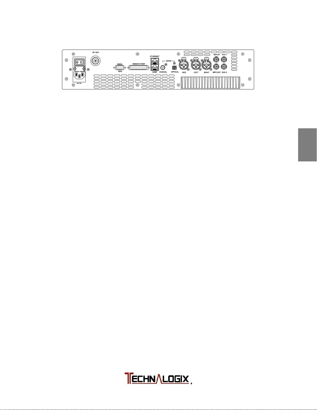
Panel Connections
AC IN: Single phase AC input to feed internal AC/DC switching power supplies.
Check with factory as not all power supplies are universal 110/220V.
RF OUT: FM modulated RF carrier output (N female or 7-16 DIN female)
RBDS/RDS: Configuration and control of RBDS/RDS encoder in transmitter
accomplished through RS232 (female) connector.
REMOTE PORT: Parallel parameter interface (DB25 female)
ETHERNET: Remote control and monitoring via Ethernet (RJ45 jack)
SNMP: Simple Network Management Protocol (SNMP) remote control and
monitoring (RJ45)
S/PDIF COAX: Digital audio input, Sony/Phillips Digital Interface, coaxial (RCA female)
S/PDIF OPTICAL: Digital audio input, Sony/Phillips Digital Interface, optical (Toslink female)
AES (digital): Digital audio input, AES/EBU professional audio interface (XLR female)
LEFT (analog): Analog audio input, left channel, (XLR female)
RIGHT (analog): Analog audio input, right channel, (XLR female). For Mono operation,
use the Right input.
MPX IN: External MPX input. Used when external stereo encoders or processors
present. (BNC female)
MPX OUT: MPX output signal from exciter. Used for external processing. (BNC
female)
SCA1/SCA2: Input connection from SCA generator or source, intended for 60 to 99
kHz. Typically modulated to 10%, or 7.5 kHz deviation.
1
2
3
4
5
6
7
8
9
10
Safeguards
Warranty
Terms and
Operation
Principle of
Installation
Operation
Control System
RF Components
Power Supply
Maintenance
Troubleshooting
Page 16

Initial Hook Up
1. Ensure that the antenna has been swept and, ideally, has a return loss of
greater than 20dB (VSWR = 1.2:1). This should be done before connecting
the antenna cable to the system’s output. The power amplifier’s control
system allows the user to change the VSWR trip point up to a maximum level
of 1.8:1, unless a custom VSWR protection system has been requested.
Strive for the lowest possible return loss to maximize transmission distance
and improve operating performance. Unless requested otherwise at the time
of purchase, VSWR levels between the trip point set by the user and 1.8:1 (or
custom VSWR trip point) will cause a fold back in power. VSWR levels past
1.8:1 (or custom VSWR trip point) will cause the system to shut down or fold
back with attenuation to avoid damage.
2. Place the amplifier in its permanent location near a receptacle supplying the
required AC or DC mains voltage.
3. Place an appropriate AC or DC power line protector, conditioner, and/or surge
suppressor across the supply line. This small investment is highly
recommended to protect the equipment from power surges and spikes (not
covered by warranty).
4. Install a lightning surge arrestor or Gas Discharge Tube (GDT) on the coax
near the antenna to protect the amplifier. This small investment is highly
recommended to protect the equipment from lightning (not covered by
warranty).
5. Connect the transmitting antenna cable to the RF OUT female connector on
the PA enclosure’s RF output. On units that have a separate filter or
filter/power supply enclosure after the power amplifier enclosure, ensure to
connect the transmitting antenna cable on the last enclosure in the chain to
the RF Out and connect the RF coaxial between the power amplifier and the
second enclosure in the chain. The system must be loaded into a 50-ohm
load before any power is turned on for over-the-air systems. The Wiring
Hookup is included in the Quickstart package included in shipping and
visually summarizes the aforementioned information.
1
2
3
4
5
6
7
8
Safeguards
Warranty
Terms and
Operation
Principle of
Installation
Operation
Control System
RF Components
Power Supply
9
Maintenance
10
Troubleshooting
Page 17

6. Connect the desired audio source connection, analog mono or stereo, digital
audio, or MPX. Subcarrier signals can be connected to the SCA1 or SCA2
BNC connectors.
7. Connect additional control/monitoring cables if desired. SNMP or Ethernet
should be connected to the lower RJ45 on the back panel. Remote port
connections are made to the DB25 connector and the internal RDS in
controlled by RS232 on the DB9 connector.
At this stage, the system is set up and ready to do a preliminary start up, as
outlined in the “Operating Procedure” section.
1
2
3
4
Safeguards
Warranty
Terms and
Operation
Principle of
Installation
5
Operation
6
Control System
7
RF Components
8
Power Supply
9
Maintenance
10
Troubleshooting
Page 18
Operating Procedure
Assuming the previous installation instructions have been completed and
cautions noted, and the power amplifier is ready to receive a properly modulated
RF signal, proceed with the following steps to place the system in operation. The
power amplifier has been factory aligned for a specific frequency (per system
specification), signal levels and optimum performance.
IT IS HIGHLY RECOMMENDED THAT YOU RUN YOUR SYSTEM INTO A
DUMMY LOAD BEFORE INSTALLING TO MAKE SURE THERE ARE NO
DAMAGES CAUSED IN SHIPPING AND THE UNIT IS RUNNING PROPERLY
1. Verify that all control and RF cables are tight and properly seated in or on the
mating connector.
2. Plug in the desired audio source: analog (left and right for stereo), digital or
MPX. For mono audio use the Right XLR input.
3. With the power amplifier loaded into the antenna, cavity, alternative load, or
dummy load power up the amplifier by turning on power supply either via the
ON/OFF switch on the back of the power amplifier.
4. Verify that the power amplifier fans are all on. The power amplifier fans are
powered via DC voltage so this is an indication that the power supply is
started and running. There may be fans installed in the filter or power supply
enclosures, if applicable.
5. The internal soft start circuitry will turn the bias voltages off until the power
supply to the amplifier pallets is fully stable. The front display indicates when
the soft start is running with either a displayed message when an LCD option
is installed or via maximum attenuation when a touch screen option is
installed. Once complete, the Forward and Reflected Power, Power Supply,
and Temperature readings will appear on the display. Deviation is shown on
the FM screen.
6. Adjust RF output power on the power amplifier to about 10% of rated forward
power. The output power level is adjusted from the power amplifier’s RF
Levels screen. Then turn the carrier on, the Carrier On/Off is in the top right
corner of the touch display on all screens. If the unit contains more than one
final amplifier pallet (illustrated in your Block Diagram included in the
Quickstart package), ensure that the final pallet currents on the multiple finals
all match within 10% of each other. With multiple finals, the final pallet
currents should always match within this range under all operating conditions.
Front panel readings will vary slightly upon turn on. Steady state parameters
can be taken after approximately one hour.
1
2
3
4
5
6
7
8
9
10
Safeguards
Warranty
Terms and
Operation
Principle of
Installation
Operation
Control System
RF Components
Power Supply
Maintenance
Troubleshooting
Page 19
7. Ideally, the RFL Power should read zero. However, should a high VSWR be
detected, the system will automatically fold back. Under normal conditions, a
well installed and setup system should indicate RFL power less than 3% of
FWD power.
8. Adjust RF output power on the power amplifier to desired level. The output
power level can be adjusted from the power amplifier’s RF Levels screen.
Keep in mind that the system will fold back or shut down (depending on
severity) should the forward RF output power level exceed the trip overdrive
point.
Pease note that 100% should be the maximum FWD power. Typically,
customers run the systems at 90% to avoid occasional AC power line spikes
or transients from tripping the shutdowns. The difference of 10% will provide a
marginal difference in range (tower height will have a much more significant
effect on range in the case of over-the-air) or cavity excitation.
9. Verify that the power supply reads correctly (see supplied final inspection
sheet for factory settings of power supply levels) on the display of the power
amplifier. You should see no more than 3% fluctuations in DC supply voltage,
and even less with a properly conditioned AC source to the power supply.
10. Look at the transmitted output using suitable test equipment. If the output
quality is unsatisfactory, check the input signals, connections to the antenna
system, antenna and transmission line VSWR, and the physical condition of
the antenna.
11. Select the appropriate input from the FM Controls screen on the front panel.
12. Adjust the attenuation for the input if needed from the Audio Levels screen on
the front panel. Check the modulation level on the main RF Display or FM
display on the front panel.
13. After warm up, compare the temperature of the equipment from the front
display to the temperature recorded in the final inspection sheet, included in
shipping. Assuming ambient temperatures are close (our factory is typically
around 18 to 25˚C), your temperature reading should be very close to the
factory reading. Use your temperature measurement as a method to monitor
fan performance (though on higher power units, fan current is also
monitored). A fan failure or air blockage will show an increase in temperature,
assuming ambient temperature is not varying.
1
2
3
4
5
6
7
8
9
10
Safeguards
Warranty
Terms and
Operation
Principle of
Installation
Operation
Control System
RF Components
Power Supply
Maintenance
Troubleshooting
Page 20

For FM broadcast applications, if the quality of transmission is unsatisfactory, the
difficulty is often with the receiving antenna or with obstructions in the path
between the amplifier/antenna and receiver. There is also a troubleshooting
section located later in this manual.
At this time, Technalogix recommends that you document your measurements to
use as a reference over time. The measurements can be made either from the
front display, or remotely via the Remote Port (DB25), Ethernet (lower RJ45), or
SNMP (lower RJ45), whose operation is explained in the Monitor and Control
System sections.
1
2
3
4
Safeguards
Warranty
Terms and
Operation
Principle of
Installation
5
Operation
6
Control System
7
RF Components
8
Power Supply
9
Maintenance
10
Troubleshooting
Page 21

Monitor and Control System
Control System Overview
The control system is used for a variety of functions, the most important of which
is ensuring that the amplifier or transmitter continues to operate in a safe manner.
The control system also allows the user to monitor and control the amplifier or
transmitter from both the front panel and remotely through the parallel port,
Ethernet, or SNMP access port.
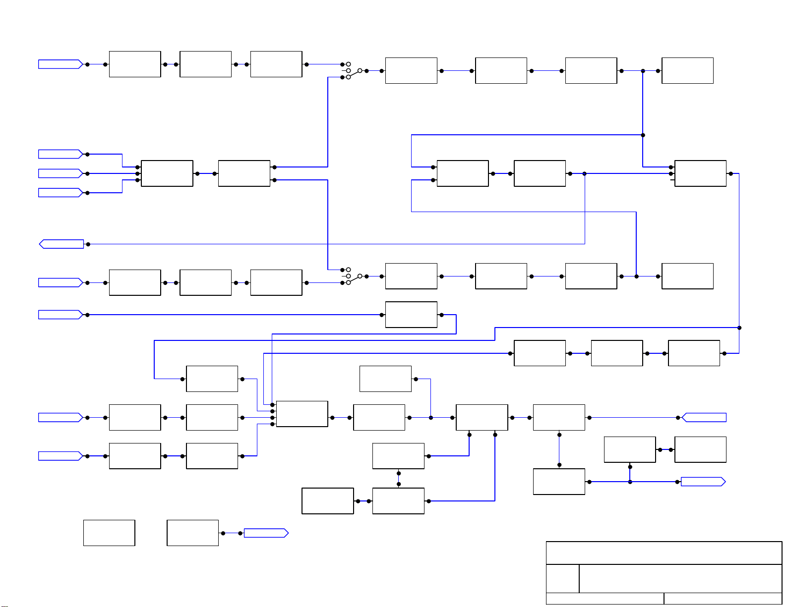
The control system is comprised of three modules. These modules work together
to provide all the functions of the control system and include: Display Interface,
Exciter (in the case of a transmitter), and Temperature Sensor modules. The
operation of each module is outlined in the following sections and illustrated in
the following block diagram. Multiple revisions of the modules may be included.
Specific revision numbers of the modules are listed on the Final Inspection
Report included in the Quickstart Package and also in the Versions screen if the
touchscreen option was ordered.
1
2
3
4
Safeguards
Warranty
Terms and
Operation
Principle of
Installation
5
Operation
6
Control System
7
RF Components
8
Power Supply
9
Maintenance
10
Troubleshooting
Page 22
FILTERRHT/MONO
I/P
TERM.
BALUN
LEVEL
PRE-
EMPHASIS
RIGHT
FILTER
METER/
DETECTION
AES3
S/PDIF
COAX
S/PDIF
OPTICAL
MPX samp
LEFT
MPX IN
SCA1
FILTER
DIG. AUDIO
RECEIVER
I/P
TERM.
LEVEL
LEVELFILTER
STEREO
DAC
BALUN
AUDIO
MIXER
DEVIATION
METER
LIMITER
LEVEL
LEVEL
STEREO
ENCODER
PRE-
EMPHASIS
VCO
MONO
FILTER
LEFT
RDS
LEVEL
RF AMP RF LEVEL
INT MPX
FILTER
GENERATOR
DETECTION
RDS
via RF transistor
voltage control
SWITCH
METER/
PILOT
DECODER
SCA2/WB
POWER
SUPPLY
LEVELFILTER
INTERFACE/
CONTROL
CANbus
LOOP
FILTER
PFDREFERENCE
LOW PASS
FILTER
DUAL DIR.
COUPLER
AGC
RF OUT
Technalogix Ltd. - A.Sivacoe
Rev ID
1.01 FM Exciter Block Diagram
Date: March 14, 2014 Page: 1 of 1
Page 23
Display Interface Module
REV 1.02 (ASY 016)
Touchscreen Option
The primary function of the Display Interface module is, as the name suggests,
providing the display and user interface for the control system. This circuit board
is mounted behind the front panel of the power amplifier enclosure(s) in the
amplifier system, near the 4.3” touchscreen or OLED display. All switch/settings
and user interface is handled through the resistive touchscreen. The touchscreen
on the front panel is connected to the Display Interface PCB through a cable.
These components provide the user with the ability to monitor the following
power amplifier or transmitter parameters from the front panel:
• Forward (incident) power at the power amplifier or transmitter output.
• Reflected (reverse) power at the power amplifier or transmitter output.
• DC voltage of the power amplifier’s or transmitter’s power supply.
• DC current in the power amplifier or transmitter.
• Temperature of the heat sink of the power amplifier or transmitter.
• The time since the amplifier or transmitter was last shut down.
• History of faults and events.
• Indication if there is attenuation added to the front end of the power
amplifier or transmitter indicating fold back in RF power (indicates amount
of attenuation).
• Settings to change the VSWR trip point shutdown between 1.1:1 and
1.8:1.
• Settings to change the RF power units between % power (maximum of
110%) or watts.
• Summary of PCB modules and assembly numbers specific to the power
amplifier or transmitter.
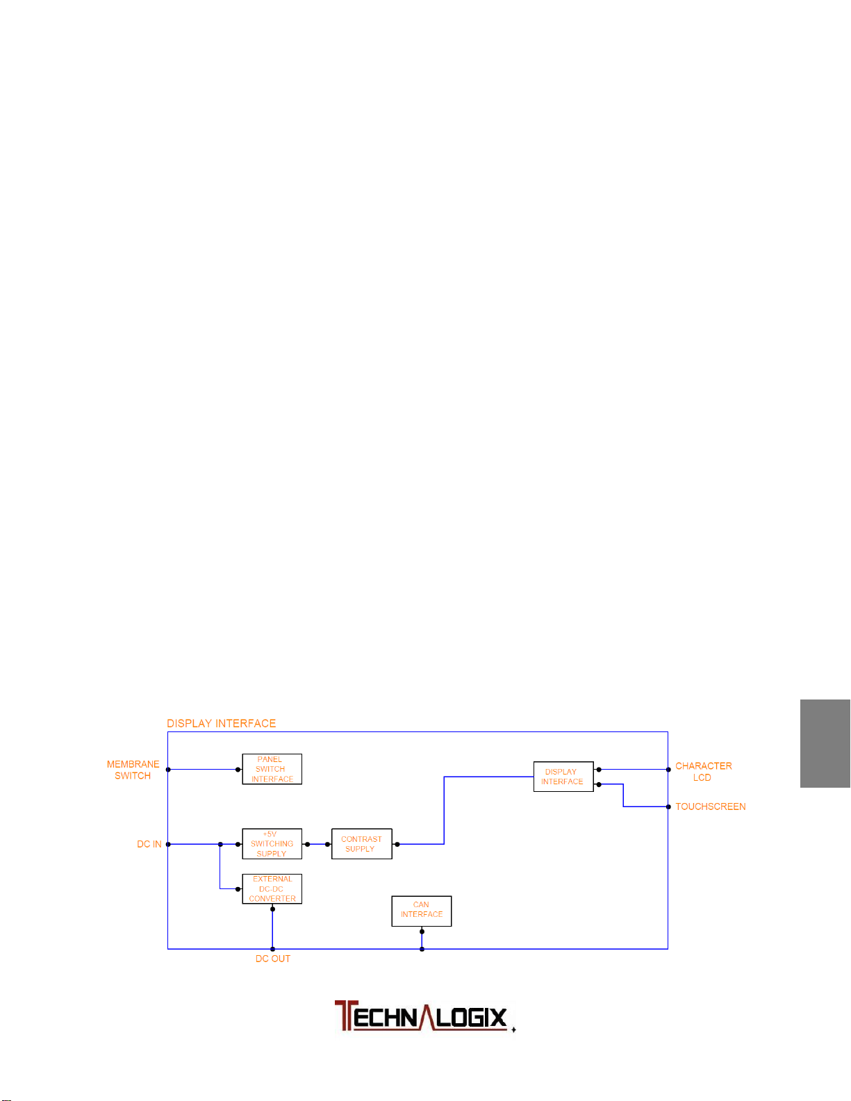
A block diagram of the Display Interface PCB follows:
1
2
3
4
5
6
7
8
9
Safeguards
Warranty
Terms and
Operation
Principle of
Installation
Operation
Control System
RF Components
Power Supply
Maintenance
10
Troubleshooting
Page 24

The hardware of the Display Interface module is based around microcontroller
(U101). This part interfaces directly with the touchscreen to provide output and
receive input from the user. It also communicates with the RF board (and DC
Distribution Module, if installed) over a Controller Area Network (CAN) bus. This
communication is facilitated by U103, and passes through a CAT5 cable attached
to connector J104 and J105. The communication link with the RF module allows
the Display Interface Module to receive information about the forward power,
reflected power, and temperature of the amplifier/transmitter, as well as relay
commands from the user to the rest of the system. If the DC Distribution Module
is installed (on higher power systems with multiple pallets), then the Display
Interface receives DC currents from the DC Distribution via the same CAN bus.
Other elements of the Display Interface module are also controlled by the
microcontroller. A buzzer (BZ101) and software status LED (D101), which flashes
when the software / microcontroller is running, are all controlled through a buffer
(U102). DC supply enters through connector J103, which powers the PCB and
also the optional DC-DC converter (based around U111), if populated. The PCB
voltage is regulated at +5V by U106 and associated circuitry. The touchscreen
interfaces to the Display Interface via connector J107.
The fuses on the Display Interface are all resettable. F102 protects the +5V line
while F101 protects the DC-DC converter, if installed.
1
2
3
4
5
Safeguards
Warranty
Terms and
Operation
Principle of
Installation
Operation
6
7
8
9
10
Control System
RF Components
Power Supply
Maintenance
Troubleshooting
Page 25
Main Screens
From each of the two main screens, the RF and the FM main screen, all of the
system’s main parameters can be viewed at a quick glance. To toggle between
these two screens, simply touch:
or
For the Main RF and Main FM screen, there are three common components
between each screen:
Level Bars: The four level bars show real time system performance and
help illustrate any transient changes that occur. Some of the
units of measure can be adjusted in Settings Menu
described later in this section.
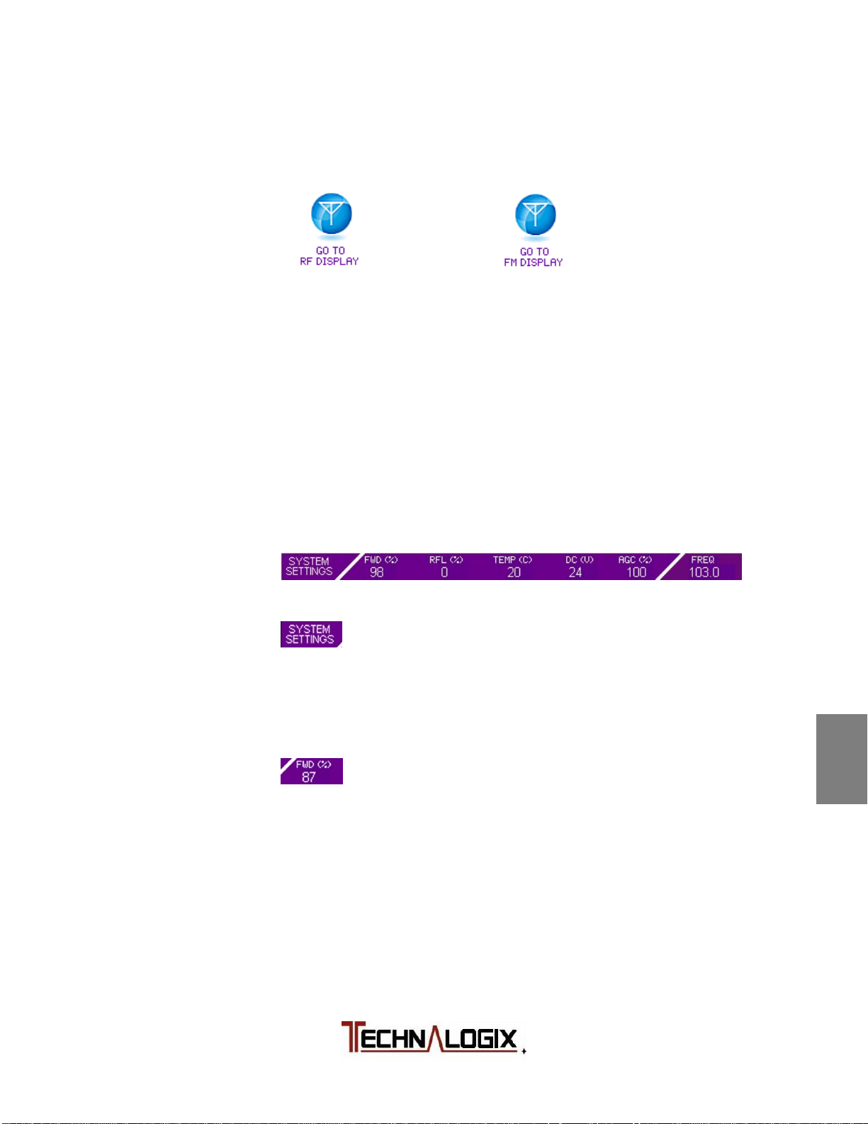
Summary Bar: The summary bar at the bottom of the screen will stay in
place no matter what screen is being viewed to allow for an
operating summary at any time, as described below:
Toggles between Main Screens and Menu Screen for
settings. The menu screen has additional settings and
monitoring over the Main Screen, and is illustrated in the
next section.
Forward RF power level in % or watts. Mimics data from
level bar. Overdrive protection starts at 110% where the
power amplifier/transmitter folds back power by adding
attenuation to the input until a safe level obtained. System
continually checks power level and tries to bring RF power
level back to where it was when fault occurred. If overdrive
occurs, a warning is displayed in red text near the top of the
touchscreen and the event recorder logs the event.
1
2
3
4
5
6
7
8
9
10
Safeguards
Warranty
Terms and
Operation
Principle of
Installation
Operation
Control System
RF Components
Power Supply
Maintenance
Troubleshooting
Page 26

Reflected RF power level in % or watts. Mimics data from
level bar. The VSWR fault occurs when the measured
1
Safeguards
VSWR of system exceeds the user-defined VSWR trip point
found in the RF Levels Menu (described later in section). If
VSWR exceeds the shutdown level, but is below 1.8:1 (or a
custom VSWR protection point), then attenuation is added to
2
Warranty
Terms and
the amplifier/transmitter input until a safe level is reached. If
the measured VSWR exceeds 1.8:1 (or a custom VSWR trip
point, then the RF carrier is turned off to protect the
amplifier/transmitter chain. Then the system will continually
check to see if it is safe to come back on. This scheme helps
3
Operation
Principle of
ensure that the system stays on air as long as possible
before doing a complete shutdown. If high reflected occurs, a
warning is displayed in red text near the top of the
touchscreen and the event recorder logs the event.
4
Installation
Temperature from sensor mounted on heat sink surface.
Shutdown trip point is factory set at a predetermined level to
5
Operation
keep the amplifier/transmitter pallets safe. Should a fan fail
inside the power amplifier/transmitter enclosure, or air
conditioning fails inside the broadcast facility causing the
temperature to exceed the trip point, the control system will
lower forward RF power until a safe level of measured
6
Control System
temperature is achieved. The system will continually try and
bring the RF power back to the same level when the fault
occurred if it is safe to do so, a warning is displayed in red
7
text near the top of the touchscreen, and the event recorder
logs the event.
RF Components
RF output power is determined largely in part by the amount
of attenuation that the control system places on the input of
8
Power Supply
the power amplifier/transmitter. Whether a fault occurs and
attenuation gets added or the user requests a change in RF
power level via the web/SNMP/Remote Port interface, the
attenuation section of the summary bar conveys important
9
Maintenance
operating information. If the user requests a change in
forward power level via the web interface, SNMP monitoring
and control, or simply via the Remote Port connector on the
10
back of the enclosure, and an asterisk (*) is placed next to
the attenuation value in the summary bar. This informs the
Troubleshooting
user whether or not the attenuation was added due to a fault
or simply because it was requested.
Page 27
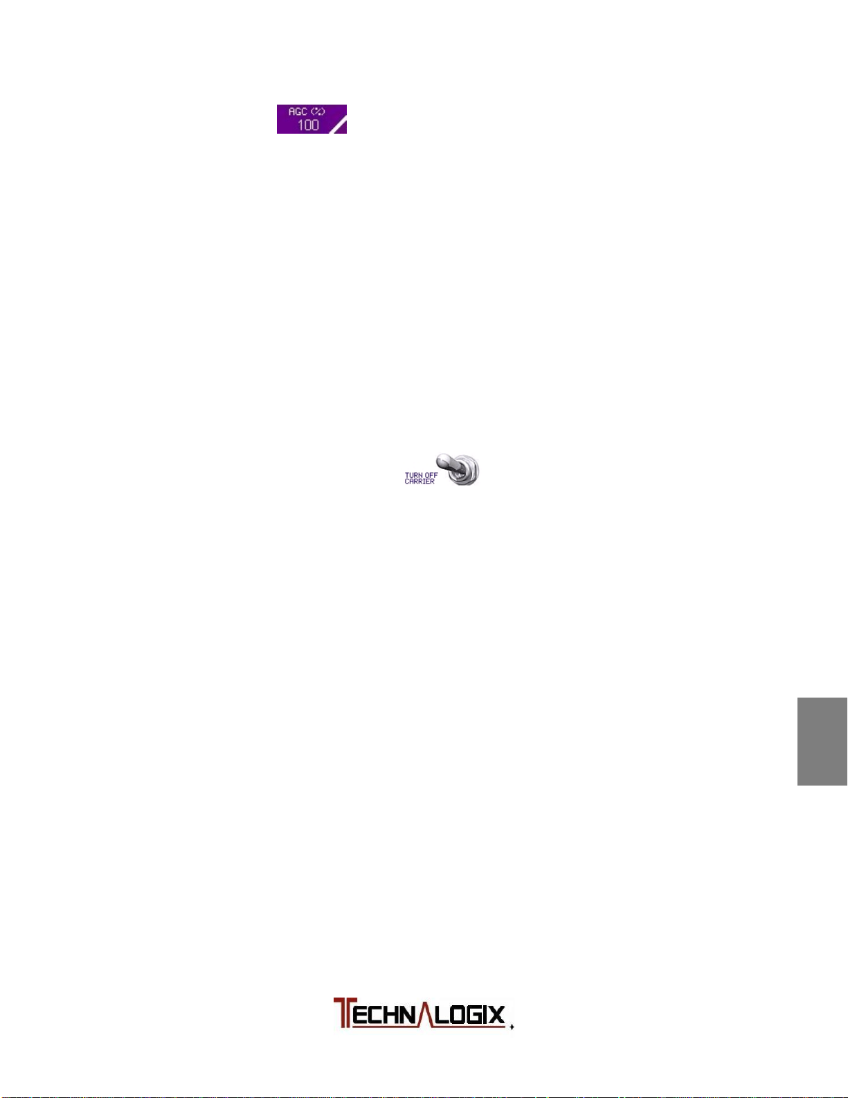
The AGC sets the desired output power level. This is set on
the RF Levels screen where it can be increased or
decreased by +-1% or +-10% increments. The current AGC
setting is shown in the RF Levels screen and on the bottom
banner. The display can be changed to show in Watts rather
than percent but the step size for setting the AGC will still be
in increments of 1 or 10%.
Carrier Switch: From any screen, the FM amplifier or transmitter carrier can
be turned on or off to facilitate adjustments, settings, and
testing/troubleshooting. To toggle carrier states, simply touch
the switch icon:
The same result occurs by turning on or off the system via
the web or SNMP interface, or through controlling of the
Remote Port. A quick beep from the on-board buzzer
signifies that the response has been taken. The power
supplies and fan will remain active while the carrier is turned
off via this switch.
If additional screens, details, and settings are required, several additional
screens can be accessed through the SYSTEM SETTINGS button described
later in this section.
1
2
3
4
5
6
7
8
Safeguards
Warranty
Terms and
Operation
Principle of
Installation
Operation
Control System
RF Components
Power Supply
9
Maintenance
10
Troubleshooting
Page 28
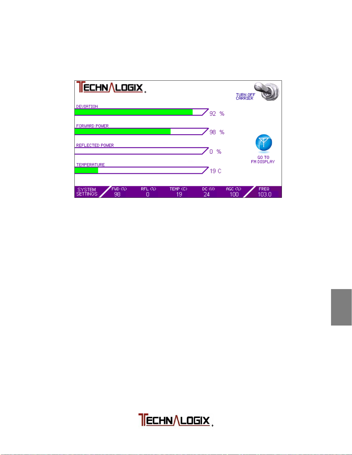
Main RF Screen
The Main RF Screen summarizes key parameters for the RF carrier of the FM
signal, as illustrated below:
FORWARD POWER: This is the power heading out of the power amplifier or
transmitter to the antenna or load, measured in watts or scaled percentage,
depending on how the units are set in the Settings Screen).
REFLECTED POWER: This is the power coming back in to the power amplifier
or transmitter from the antenna or load, measured in watts or scaled percentage,
depending on how the units are set in the Settings Screen). As there is no
internal circulator or isolator installed within the enclosure, it is important to
minimize VSWR with a good quality antenna installed using proper broadcast
techniques. Ice build-up on the antenna and damages to 50 ohm transmission
line can also generate damaging reflected power.
TEMPERATURE: The temperature is measured on top of the heatsink near the
final transistors and displayed here. User can toggle between Celsius and
Fahrenheit from the Settings Screen. In the event that this temperature exceeds
the factory set trip point, the RF carrier level will fold back to protect the unit.
Common causes for high temperatures can include failed internal fans or air
conditioning in the broadcast facility or a blocked fan.
DC VOLTAGE: The switching power supply DC output voltage is displayed here.
If additional screens, details, and settings are required, several additional
screens can be accessed through the SYSTEM SETTINGS button described
later in this section.
1
2
3
4
5
6
7
8
9
10
Safeguards
Warranty
Terms and
Operation
Principle of
Installation
Operation
Control System
RF Components
Power Supply
Maintenance
Troubleshooting
Page 29
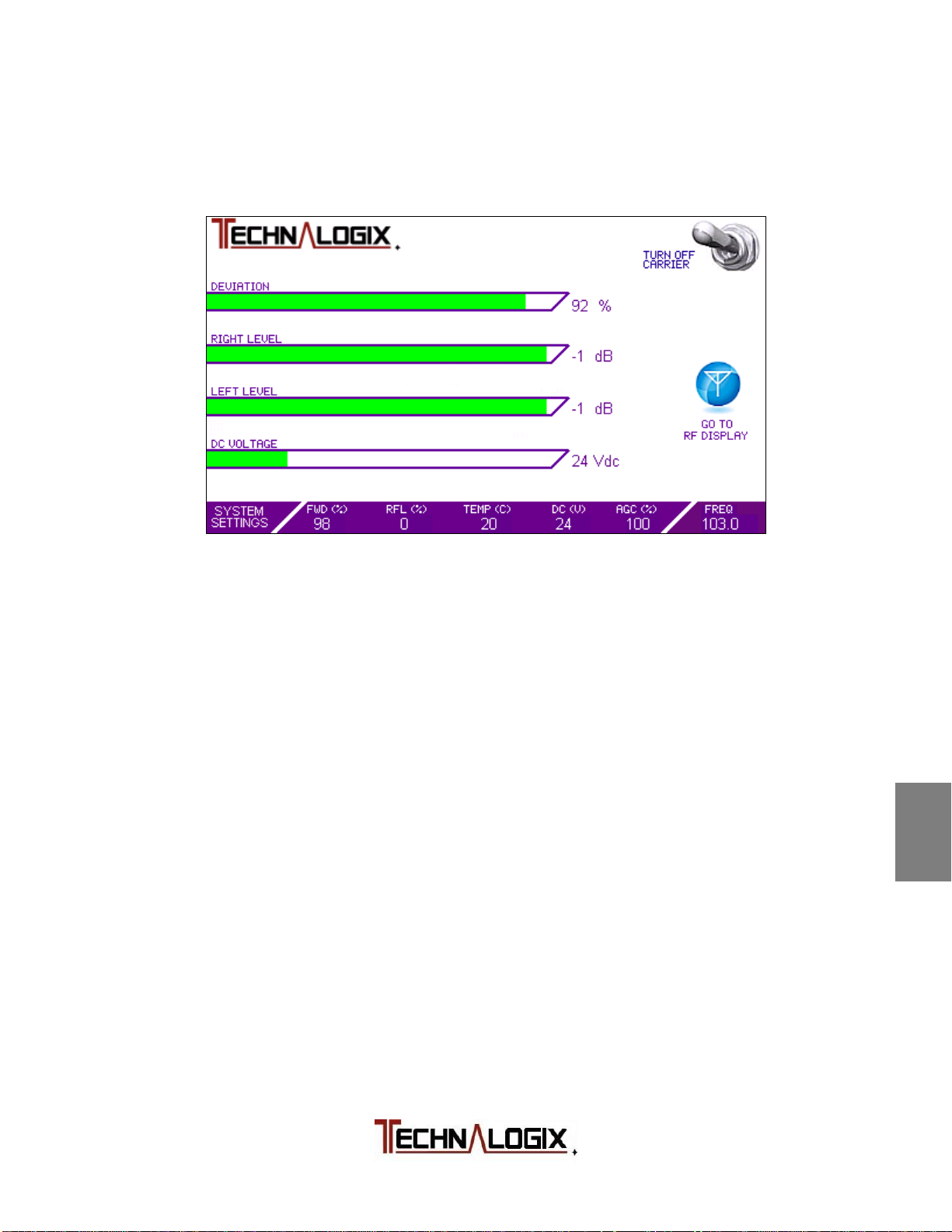
Main FM Screen
The Main FM Screen summarizes key parameters for the audio that resides on
the RF carrier of the FM signal, as illustrated below:
DEVIATION: The maximum frequency excursion from the carrier center
frequency is illustrated on this level bar. Typical maximum deviation, required by
Industry Canada or FCC, is 75 kHz to avoid bleeding into adjacent channel
bands of 200kHz bandwidths. 100% represents a full 75 kHz deviation.
RIGHT LEVEL: Right level bar represents the audio level on the right audio input
channel.
LEFT LEVEL: Left level bar represents the audio evel on the left audio input
channel.
DC VOLTAGE: The switching power supply DC output voltage is displayed here.
If additional screens, details, and settings are required, several additional
screens can be accessed through the SYSTEM SETTINGS button described
later in this section.
1
2
3
4
5
6
7
8
9
Safeguards
Warranty
Terms and
Operation
Principle of
Installation
Operation
Control System
RF Components
Power Supply
Maintenance
10
Troubleshooting
Page 30
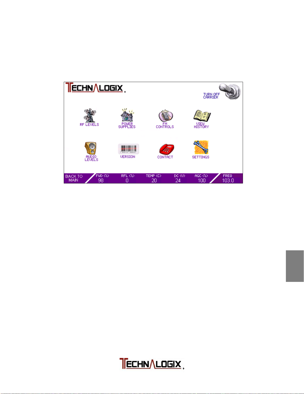
Menu Screen
The menu screen allows the user to dive into further details of the power amplifier
or transmitter operation. Pressing the BACK TO MAIN button will toggle between
the Main Screens and the Menu Screen. The Menu Screen is shown below:
Each of the menu icons on the Menu Screen allow the user to take additional
readings or make settings that are not provided from the Main RF and FM
Screens. Any changes to settings will be stored in non-volatile memory.
While the user is in the sub menu screens (anything besides the Main Screens),
full monitoring and protection is taking place. This means that as a user makes a
change to a setting or parameter that jeopardizes the power amplifier or
transmitter, the control system will provide protection, display the fault in red text
near the top of the touchscreen, and stay in the current menu.
The individual menu screens will now be covered.
1
2
3
4
5
6
7
8
Safeguards
Warranty
Terms and
Operation
Principle of
Installation
Operation
Control System
RF Components
Power Supply
9
Maintenance
10
Troubleshooting
Page 31
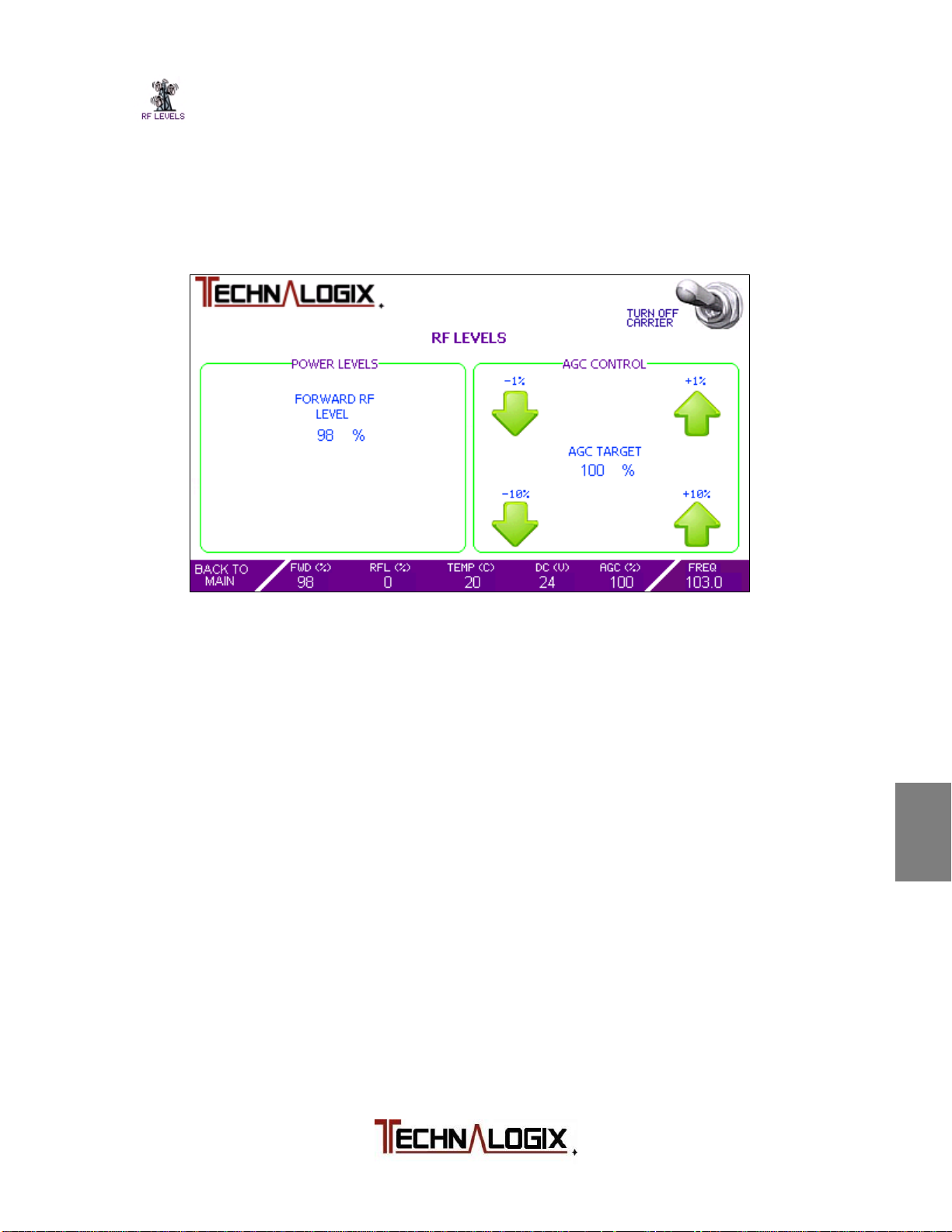
RF Levels Screen
This screen allows the user to change settings to the RF levels, including the
Forward RF level (the reflected (VSWR) trip point is changed from the Settings
screen. From the RF Levels screen, the user can also toggle between AGC and
Manual mode. The RF Levels Screen is displayed below:
To adjust Forward RF Level:
Press the up or down arrows (in either 1 or 10% increments or decrements) until
the desired Forward RF level is reached. If the adjusted level exceeds 110%, the
protection will kick in and the system will fold back the RF power to a safe level.
There may be a residual amount of Forward RF power even at 0% setting, but it
should be insignificant.
1
2
3
4
5
6
7
8
Safeguards
Warranty
Terms and
Operation
Principle of
Installation
Operation
Control System
RF Components
Power Supply
9
Maintenance
10
Troubleshooting
Page 32
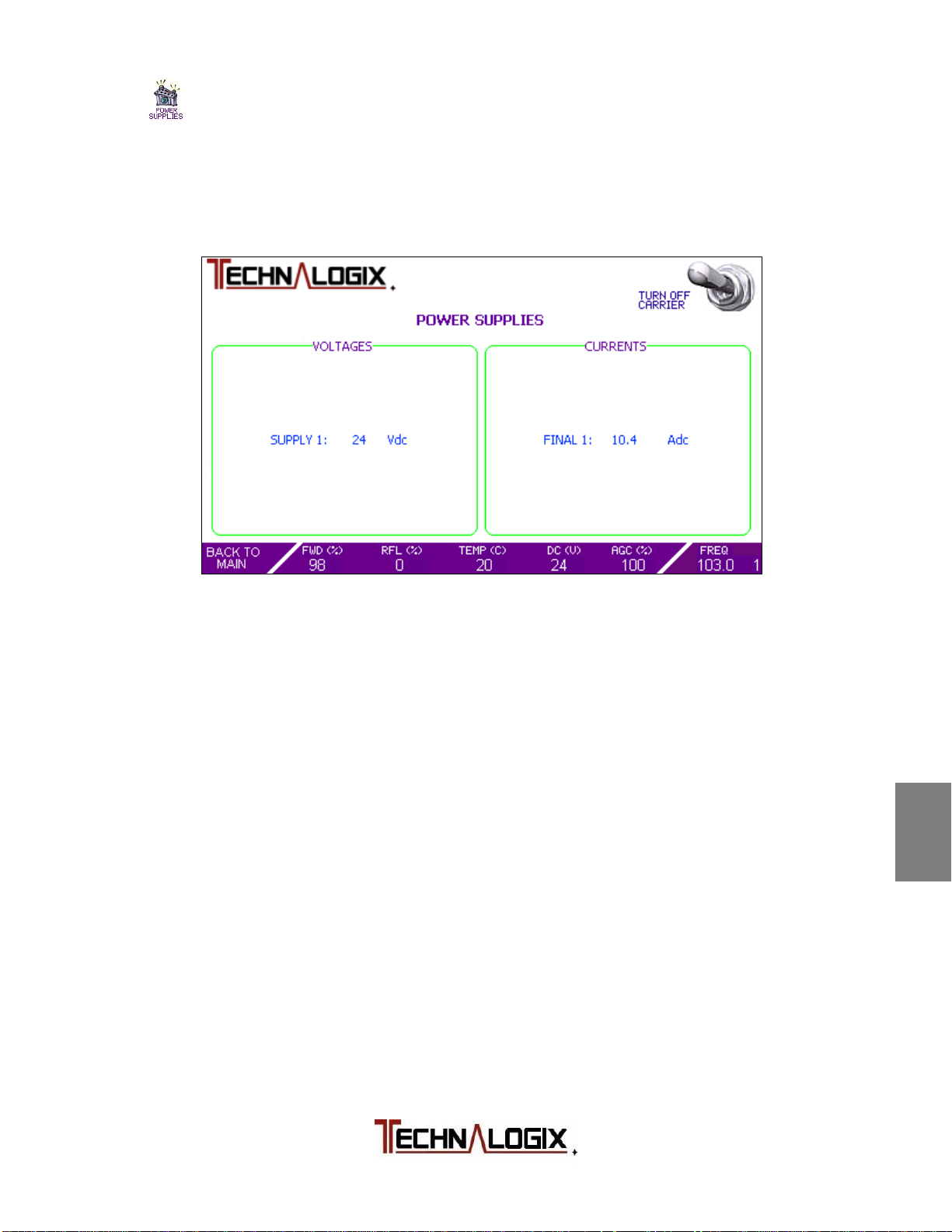
Power Supplies Screen
This screen allows the user to view individual voltage and current readings. The
Power Supplies Screen is displayed below:
DC supply voltages are nominally 24, 30, or 48Vdc depending on the system.
Readings of this voltage in the Power Supplies Screen, and on the summary bar
at the bottom of the touchscreen, should not vary more than +/- 2%.
If multiple amplifier pallets are included in the amplifier chain, then the individual
currents will all be displayed in the Currents section of the screen. In the case of
multiple pallets in the chain, typically the user should see matching of the final
pallets to within approximately 10%. Anything outside this range is usually a sign
that there may be an issue. Transistor device could be the culprit, or the tragic
spilt-drink-on-amplifier incident. Our team would be glad to walk you through any
troubleshooting issues or questions you may have.
1
2
3
4
5
6
7
8
Safeguards
Warranty
Terms and
Operation
Principle of
Installation
Operation
Control System
RF Components
Power Supply
9
Maintenance
10
Troubleshooting
Page 33
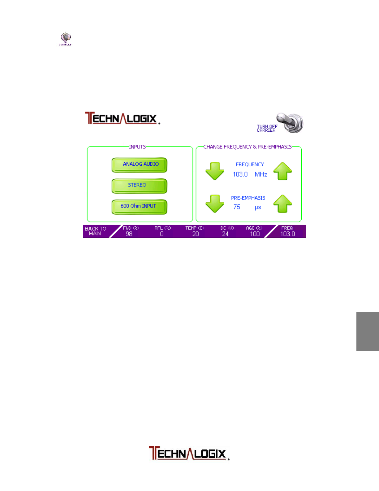
FM Controls Screen
The FM Controls Screen allows a user to setup audio inputs and FM settings. As
fun as fooling around with the smallest screwdriver you own in the back of a dark
rack sounds, all of these settings can be done from the front touch screen.
Audio Source: As Technalogix FM transmitters include analog and digital
audio inputs as standard, the user can change audio input
sources on the fly and can switch between analog and digital
audio sources. When digital audio is selected, the
Mono/Stereo selection icon changes to allow selection
between the various digital audio inputs (Toslink optical,
coax, AES).
Mono/Stereo: All Technalogix FM transmitters have a stereo encoder built
in to the exciter circuit board. The user can switch between
Mono and Stereo option by simply touching this icon on the
touch screen.
Input Impedance: When analog audio input is selected as a source, the user
can adjust the input impedance of the exciter in the
transmitter between 600 and 10k ohms.
1
2
3
4
5
6
7
8
9
Safeguards
Warranty
Terms and
Operation
Principle of
Installation
Operation
Control System
RF Components
Power Supply
Maintenance
10
Troubleshooting
Page 34

Frequency: With the exciter being agile, the user can change frequency
from the front touch screen. The step size is 100 kHz. At the
lower and upper frequency limits of the FM band, the
frequency will wrap back around.
Pre-Emphasis: Pre-emphasis adds a boost to high frequencies in the FM
signal to increase the signal above the noise floor. The FM
signal then is de-emphasized at the radio receiver end.
Users can change the amount of pre-emphasis to suit their
location and receivers. A lower pre-emphasis, say 50 us
versus 75 us, is a lighter boost, but also increases high
frequency headroom. Setting the pre-emphasis to 0 us turn
off the pre-emphasis. Standard North American preemphasis is set to 75 us on the transmitter side, while most
of the rest of the world incorporates 50 us.
1
2
3
4
Safeguards
Warranty
Terms and
Operation
Principle of
Installation
5
Operation
6
Control System
7
RF Components
8
Power Supply
9
Maintenance
10
Troubleshooting
Page 35
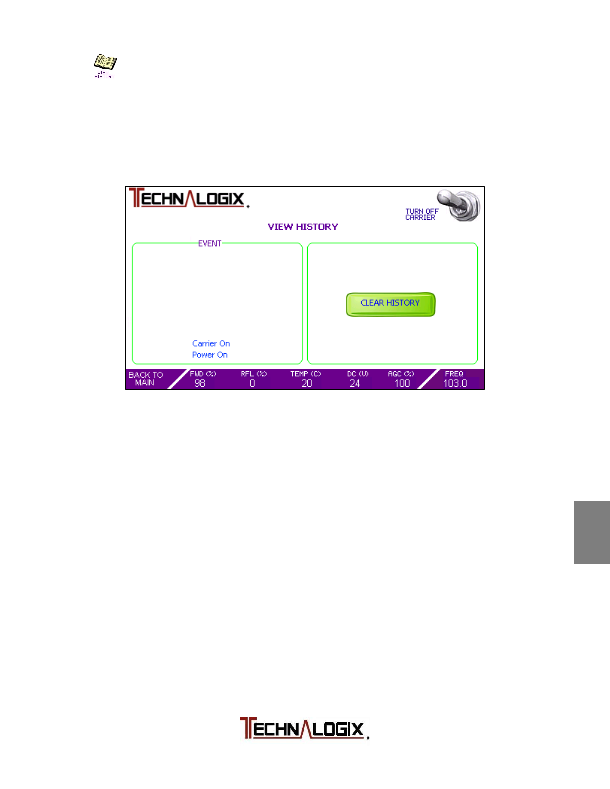
History Screen
The History Screen provides a summary of the most recent events that have
occurred in the power amplifier or transmitter. An event can either be a fault or
simply an action like turning on or off the carrier. The format of the History Screen
is illustrated below:
Ten of the most recent events are displayed on the History Screen. As more
events occur, the earliest recorded event gets displaced on the screen.
The user can clear the history screen by pressing the CLEAR HISTORY. Users
will find this screen useful in correlating events in the power amplifier or
transmitter with external events like weather and changes to the broadcast
facility’s environment.
The events are recorded in non-volatile memory so they are safe in the event of a
power outage or pesky lightning-strike-wins-fight-with-power-supply.
1
2
3
4
5
6
7
8
Safeguards
Warranty
Terms and
Operation
Principle of
Installation
Operation
Control System
RF Components
Power Supply
9
Maintenance
10
Troubleshooting
Page 36
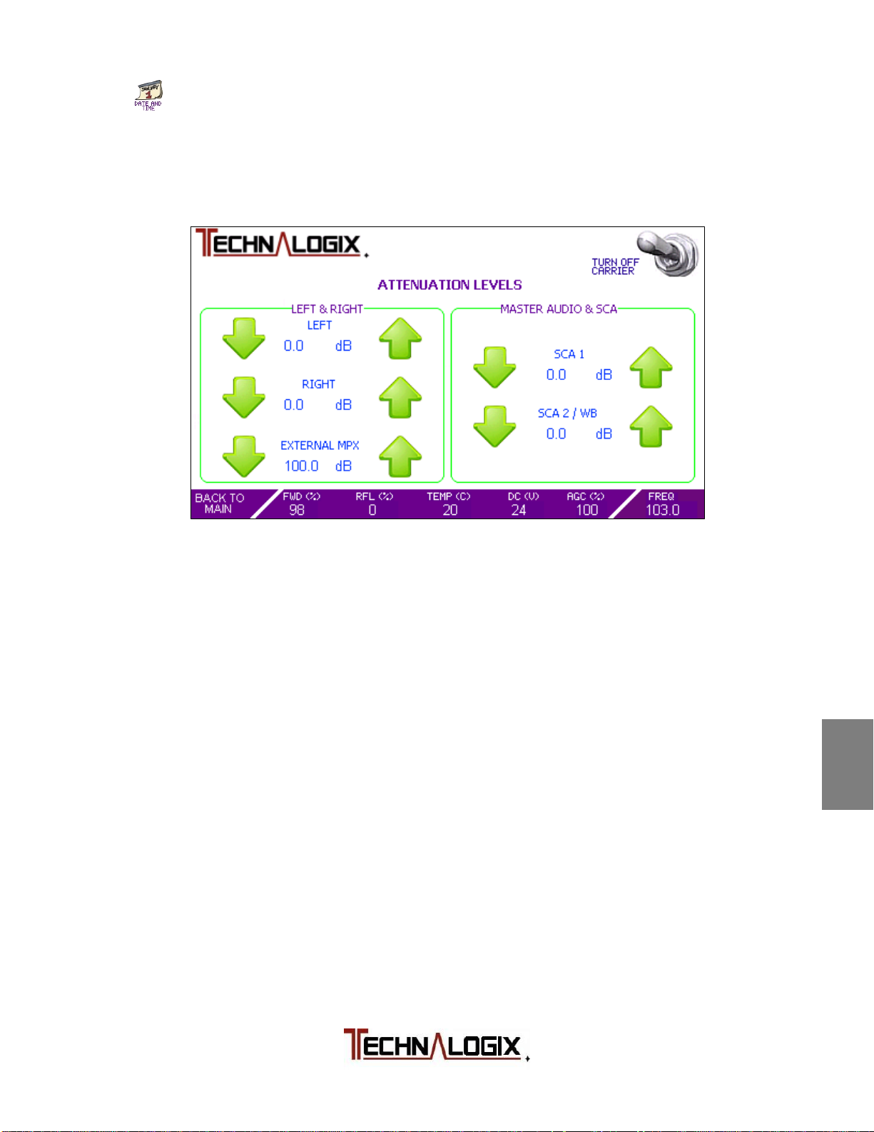
Audio Levels Screen
The Audio Levels Screen allows the user to tweak audio input levels all from the
front touch screen.
Step sizes will vary from 0.5 dB up to 2.0 dB depending on the current audio,
MPX, and SCA input levels.
Attenuation levels of 100 dB indicate that attenuation is at maximum for that
particular input signal.
1
2
3
4
5
6
7
Safeguards
Warranty
Terms and
Operation
Principle of
Installation
Operation
Control System
RF Components
8
Power Supply
9
Maintenance
10
Troubleshooting
Page 37
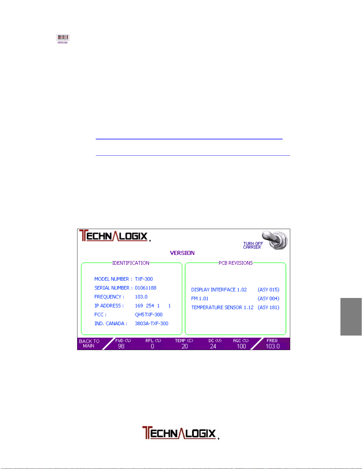
Version Screen
The Version Screen contains no user-settable items, but is intended as an
identification screen to the user. It also helps Technalogix maintain its unmatched
service reputation by allowing our technicians and Service team to know exactly
what versions of PCBs are inside a customer’s unit, even several years down the
road. The versions can then be correlated to factory documentation. In addition,
current government certification numbers are included for Industry Canada and
FCC. Please contact Technalogix if you require copies of the actual grants, or
visit:
FCC: https://fjallfoss.fcc.gov/oetcf/eas/reports/GenericSearch.cfm
(grantee code QH5)
Ind. Canada: http://www.ic.gc.ca/app/sitt/reltel/srch/nwRdSrch.do?lang=eng
(company 3803)
Finally, general information is included in the Version Screen for users who may
not be familiar with the equipment and do not want to venture into the dusty
abyss behind the rack or cabinet searching for tiny ID tags. The Version Screen
is illustrated below:
1
2
3
4
5
6
7
8
9
Safeguards
Warranty
Terms and
Operation
Principle of
Installation
Operation
Control System
RF Components
Power Supply
Maintenance
10
Troubleshooting
Page 38
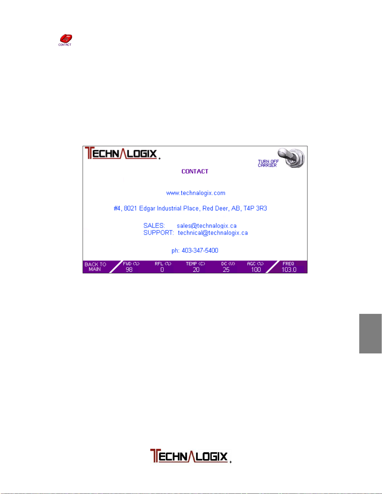
Contact Screen
The Contact Screen provides an easy means for the user to get in touch with
Technalogix for anything. Whether they have a technical or installation question
or simply want to chat about how gosh darn cool our equipment is, Technalogix
welcomes questions, feedback, and contact.
If you are in the area, please feel free to stop by to tour the facility, test drive
some state of the art products, or get a refresher on some training.
1
2
3
4
5
6
Safeguards
Warranty
Terms and
Operation
Principle of
Installation
Operation
Control System
7
RF Components
8
Power Supply
9
Maintenance
10
Troubleshooting
Page 39
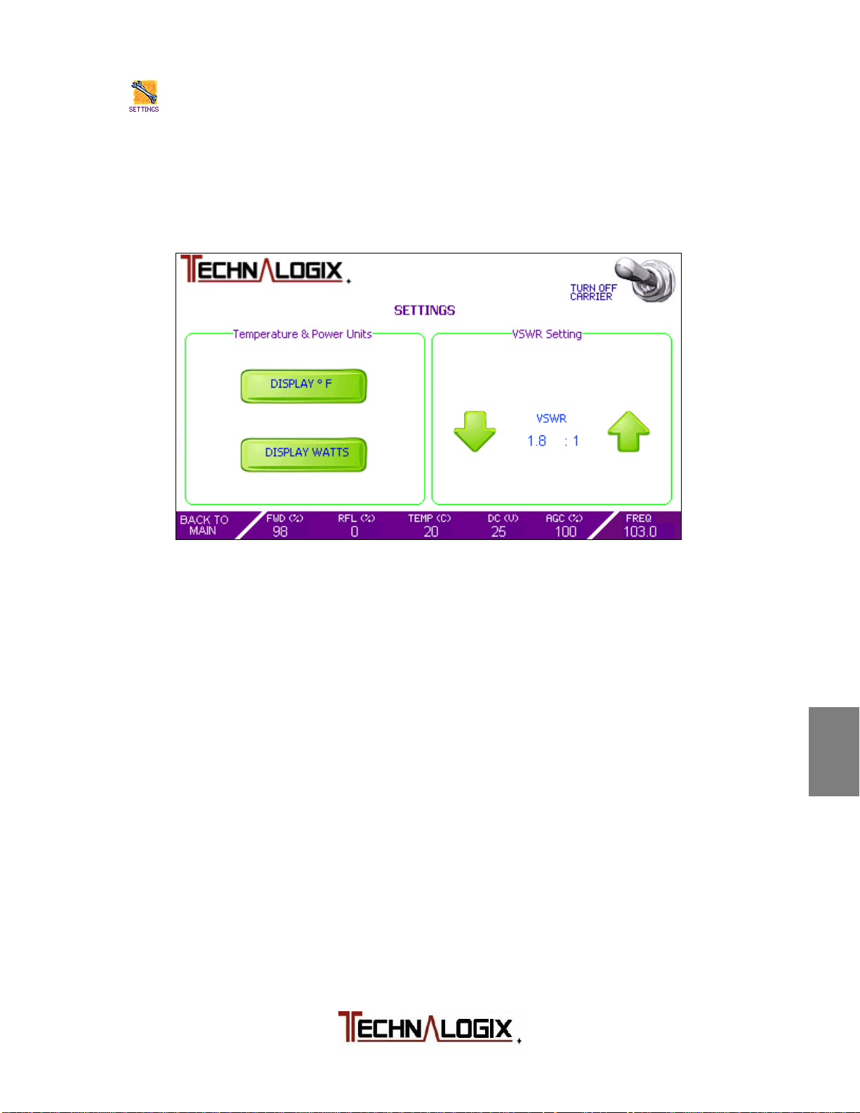
Settings Screen
“You say tomato...”
The Settings Screen allows the user to modify some of their preferences on how
information is displayed on the touchscreen, as seen in the figure below:
Pressing the DISPLAY ⁰ F button will convert all temperature readings to degrees
Fahrenheit from Celsius (and vice versa). Temperature protection trip points are
factory set.
Similarly, the user can switch between watts or percentage for their RF power
readings. When in percentage mode, the power amplifier or transmitter is
designed for a maximum operating power of 100% with overdrive protection
typically at 110%.
To change the VSWR Shutdown Trip Point:
Use the up and down arrows to set the VSWR shutdown trip point to between
1.1:1 and the factory determined upper limit. If a measured VSWR is found above
the set trip point, but below the factory determined upper limit, then the system
will fold back the forward power to a safe level. If the measured VSWR exceeds
the factory determined upper limit, then the carrier will be initially turned right off.
Technalogix may have provided custom firmware with the amplifier or transmitter
that may deviate from the above operation. Please consult factory for any clientordered custom settings.
1
2
3
4
5
6
7
8
9
10
Safeguards
Warranty
Terms and
Operation
Principle of
Installation
Operation
Control System
RF Components
Power Supply
Maintenance
Troubleshooting
Page 40

FM Exciter Module
REV 1.01 (ASY 0070)
The FM Exciter module accepts analog and digital audio inputs, processes the
audio, and then modulates the audio onto an FM carrier in the range of 87.5 to
108.0 MHz. This modulated signal is then fed into a small gain stage before
passing the signal off to the final gain amplifier stage(s).
Analog input can be balanced or unbalanced, though the former will provide a
higher quality signal. Digital audio can be sourced from AES, S/PDIF optical
(Toslink), or S/PDIF coaxial.
The following pages illustrate the schematics of the FM Exciter module.
1
Safeguards
2
Warranty
Terms and
3
Operation
Principle of
4
Installation
5
Operation
6
Control System
7
RF Components
8
Power Supply
9
Maintenance
10
Troubleshooting
Page 41
Temperature Sensor Module
REV 1.13 (ASY 0183)
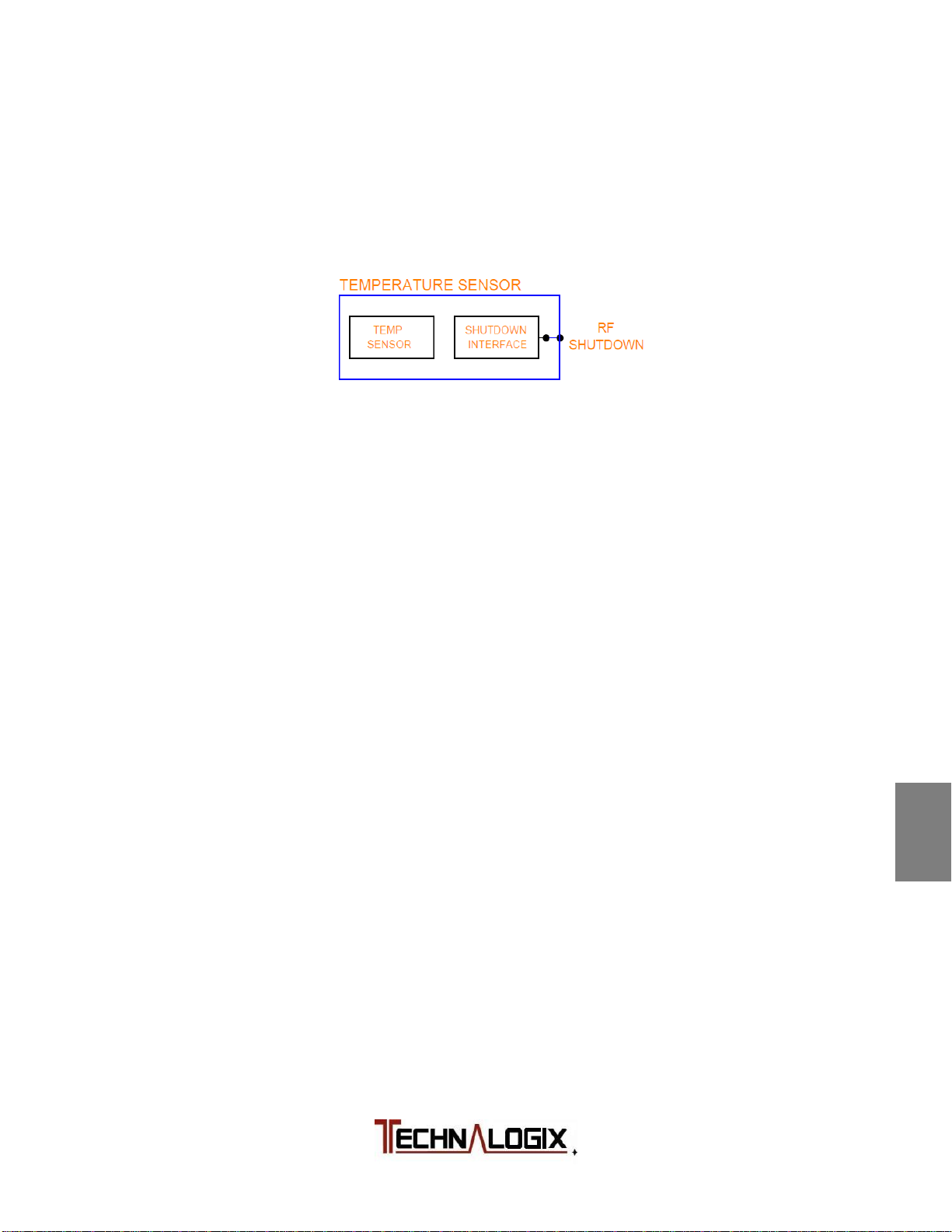
The Temperature Sensor module is a small board mounted to the main heatsink
of the amplifier/transmitter. The main purpose of the temperature sensor module
is to take temperature readings of the heatsink. The following is a block diagram
of the Temperature Sensor module:
The temperature sensor IC is U701 which, after it has taken a reading, relays the
digital information to the RF PCB module through J700. Also passing through
J700 is a driver disable signal coming from the RF PCB module. The
Temperature Sensor module simply takes this signal and passes it through to a
pad, where a wire connects it to the driver or first gain stage pallet.
In custom applications, there may be multiple temperature sensors installed onto
a heatsink or throughout the system.
1
2
3
4
5
Safeguards
Warranty
Terms and
Operation
Principle of
Installation
Operation
6
7
8
9
10
Control System
RF Components
Power Supply
Maintenance
Troubleshooting
Page 42
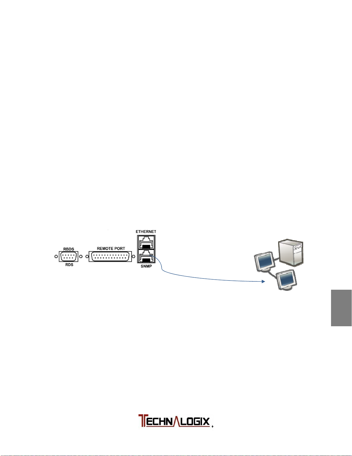
Web Interface
To access the Technalogix Adrenaline Web Interface, a series of four simple
steps are required:
1. Connect power amplifier/transmitter to your network/PC
2. Open web browser for monitor and control
3. Optimize user parameters
The following pages will describe each step in detail. Descriptions specific to the
user’s computer, router, or network setup are limited due to the differences in the
multitude of networking equipment.
1. Connect Power Amplifier/Transmitter to your Network/PC
Connect an Ethernet cable from the RJ45 port (labelled ETH / SNMP – use
bottom connector) on the back panel of the power amplifier or transmitter to
your network’s Ethernet connection. Most new computers can do this with a
standard Ethernet cable but older network cards may require a crossover
Ethernet cable.
If preferred in place of the touch screen, a computer can be plugged directly
into the Ethernet port on the power amplifier/transmitter to directly access the
on-board web interface.
Turn on the power amplifier or transmitter to establish communication
between the power amplifier and the network.
The Adrenaline control system in the power amplifier or transmitter will source
an internal IP from your router or you can set this manually (see Optimize
User Parameter section).
1
2
3
4
5
6
7
8
9
10
Safeguards
Warranty
Terms and
Operation
Principle of
Installation
Operation
Control System
RF Components
Power Supply
Maintenance
Troubleshooting
Page 43
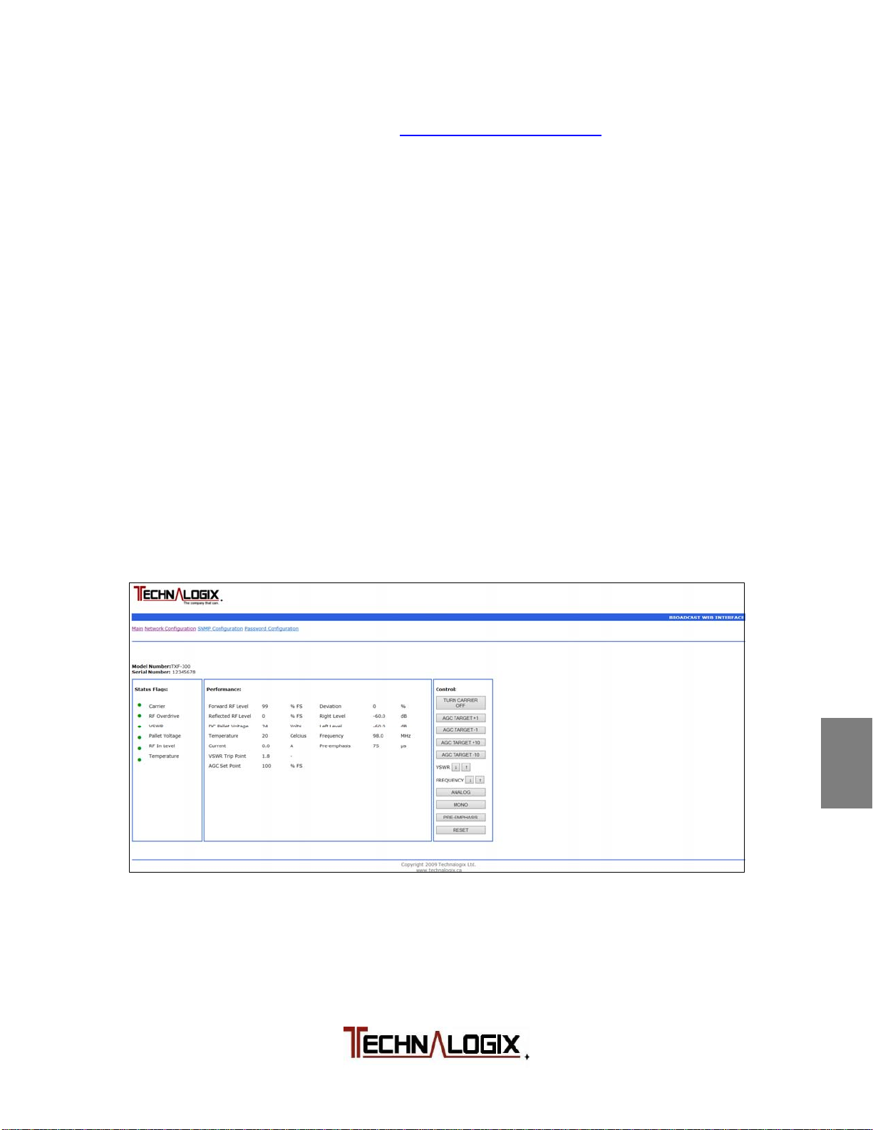
2. Open web browser for monitor and control
The default internal address is http://adrenaline/index.htm. Type this default
internal address into the URL address bar of your favorite web browser. The
web pages cannot be accessed until you have established basic
1
Safeguards
communication with the power amplifier or transmitter (turned on).
2.1 Web Page Password Protection
2
Warranty
Terms and
After entering the above internal address into a web browser, you will be
asked for a password. Initially, please use the following:
3
Operation
Principle of
username: admin
password: admin
The password can later be changed (see Optimize User Parameter section).
2.2 Main Page Description
4
Installation
After entering the login information, the main page is then shown on the
browser, as illustrated below for either single amplifier systems or multiple
5
Operation
amplifier systems that are combined:
6
Control System
7
RF Components
8
Power Supply
9
Maintenance
10
Troubleshooting
Page 44

The model number and serial number of the unit are displayed in the top left
of the browser screen.
The Status Flags section provides the user with feedback from the system.
Specifically, there are status flags for:
RF Carrier is on or off
Forward RF in Overdrive (>110% Full Scale (FS) )
High VSWR
Pallet Voltage Supply Good
RF In Level Good
High Temperature
The Performance section provides the user with specific parameters and
measurements in the system. Measurements that can be viewed from the
Performance box are:
Forward RF Levels as a % of Full Scale (FS)
Reflected RF Levels as a % of FS
DC Supply Voltage in volts
Temperature in °C
Current of pallet(s) in Adc
VSWR Trip Point Limit
AGC measured against 100% FS
Deviation
Right Level/Left Level input attenuation
Frequency in MHz
Pre-Emphasis, selectable between 0, 25, 50, or 75 us
1
2
3
4
5
6
7
Safeguards
Warranty
Terms and
Operation
Principle of
Installation
Operation
Control System
RF Components
8
Power Supply
9
Maintenance
10
Troubleshooting
Page 45

The Control section of the web interface screen allows the user to control
functions inside the equipment, including:
Turn Carrier On/Off - Turn the Carrier on/off
AGC - Increase the Carrier by removing attenuation (steps of 1
or 10 dB)
VSWR ↑↓ - Increase or Decrease the VSWR Trip point by 0.1
between 1.1:1 and factory determined limit.
Frequency ↑↓ - Increase or Decrease the FM carrier frequency
(MHz)
Analog/Digital – Toggle between analog or digital audio inputs
Mono/Stereo – Toggle between mono or stereo
Pre-Emphasis – Toggle between no added emphasis, or 25, 50,
or 75 us emphasis
Reset - Forces the system to reboot
1
2
3
4
Safeguards
Warranty
Terms and
Operation
Principle of
Installation
5
Operation
6
Control System
7
RF Components
8
Power Supply
9
Maintenance
10
Troubleshooting
Page 46
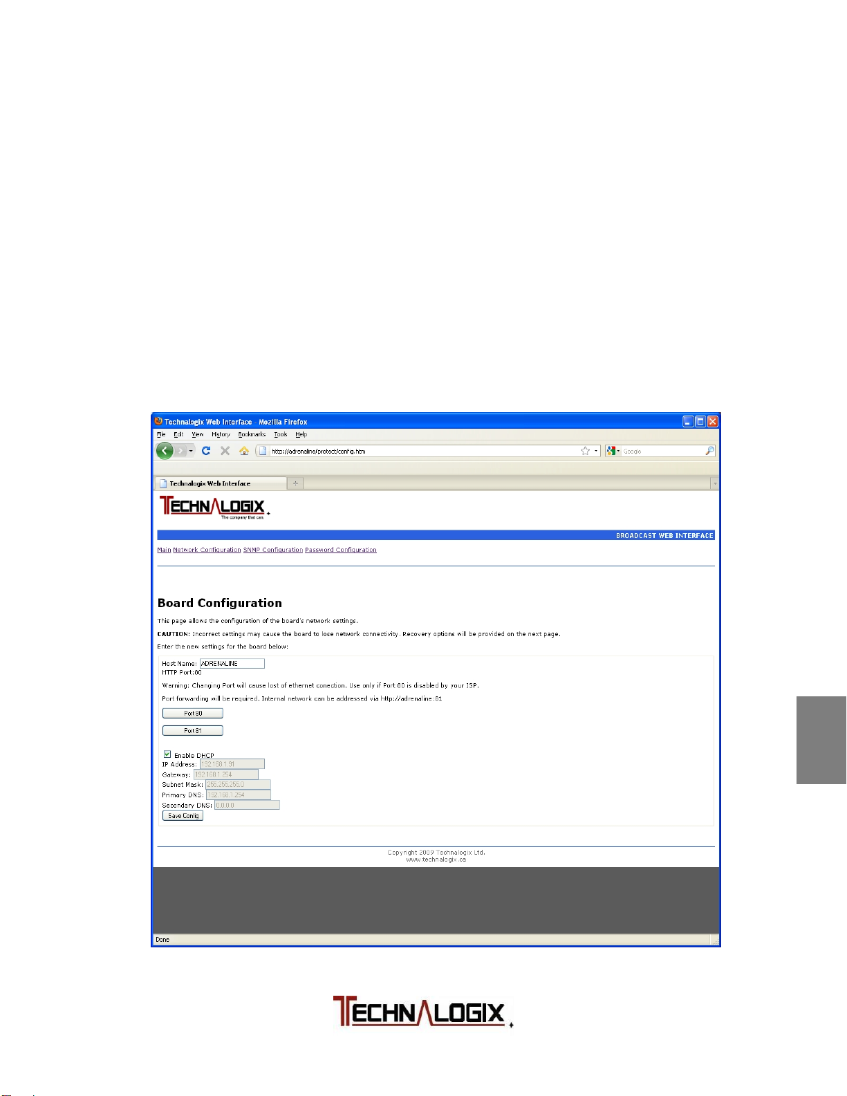
3. Optimize user parameters
Also on the main web Ethernet page, along the top, are links to the other user
parameter pages:
Main – Returns to Main Index page
Network Configuration
SNMP Configuration
Password Configuration
The following sections describe the user parameter pages in detail.
3.1 Network Configuration
The Network Configuration page allows the administrator to optimize the
network settings to best suit their application.
1
2
3
4
5
6
7
8
9
10
Safeguards
Warranty
Terms and
Operation
Principle of
Installation
Operation
Control System
RF Components
Power Supply
Maintenance
Troubleshooting
Page 47
3.1.1 Host Name
The Host Name shows the current webpage name (default is ADRENALINE).
Enter a new name here if you wish to change this.
For example entering YourCompany will make the web address:
http://yourcompany/index.htm
3.1.2 HTTP Port
The HTTP Port shows the current port used for internet access, 80 or 81. Port
80 is the default and is the accepted standard. Port 81 is available because
some internet providers block access to port 80 unless you pay more.
Be very careful changing HTTP ports as it can be difficult to go back to an
original port.
You can force a web browser to use port 81 by address to:
http://adrenaline:81/index.htm
To use this with an internet address will require port forwarding. Consult your
routers manual to set this up.
3.1.3 IP Addressing
With DHCP enabled the system will automatically try to find a router and
acquire an IP address. If you want to set this manually, uncheck the Enable
DHCP box and enter it below then click Save Config.
To view the webpage from the internet rather than an internal network you
need an external IP address, generally provided by your internet provider.
Note that you can only have one web server using the same port. With this,
anyone can access the system over the internet with something like:
http://www.yourcompanywebaddress.com/adrenaline
1
2
3
4
5
6
7
8
9
Safeguards
Warranty
Terms and
Operation
Principle of
Installation
Operation
Control System
RF Components
Power Supply
Maintenance
10
Troubleshooting
Page 48
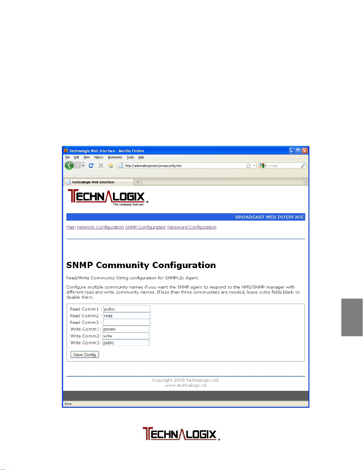
3.2 SNMP Configuration
3.2.1 SNMP Communities
The SNMP Configuration page allows you to set the SNMP communities. Set
these to limit access to the system via SNMP.
Default communities are READ: public
read
WRITE: private
write
public
1
2
3
4
Safeguards
Warranty
Terms and
Operation
Principle of
Installation
5
Operation
6
Control System
7
RF Components
8
Power Supply
9
Maintenance
10
Troubleshooting
Page 49

3.2.2 SNMP Management Information Base (MIB)
The Technalogix.mib file allows access to the following data via the SNMP
protocol:
Read Only
Pallet Supply Voltage - voltage level (Vdc)
Temperature - temperature in (°C)
48V Current - current on high voltage bus (Adc)
Attenuation - attenuation level
Reflected Level - reflected level as % rated full scale
Forward Level - forward level as % rated full scale
RF Input Level - input level as % rated full scale
Deviation - modulation level as %
Left Level - left audio input level shown as dB
Right Level - right audio input level shown as dB
Serial Number
Model Number
SNMP Error Flag - error flag, also for trap (see below)
VSWR Flag - error flag for high VSWR
Overdrive - error flag for overdrive
Temperature Flag - error flag for high temperature
Preemphasis - 0,25,50 or 75 us
Read/Write
Reset - 1 Reset System, 0 Normal
Carrier On - 1 Carrier On, 0 Carrier Off
Carrier Up - 1 Increase Carrier Level for AGC target 1%
Carrier Down - 1 Decrease Carrier Level for AGC target 1%
VSWR Trip point - 1-8 for 1.1:1 – 1.8:1
Frequency - 880 – 1080 for 88.0 to 108.0 MHz
Change Preemphasis - rotate through 0,25,50, and 75
AGC Setpoint - set target output power 0-100% rated power
Analog/Digital - 1 Analog audio input, 2 Digital audio input
Digital Input - 1 AES 2 SPDIF 3 TOSLINK
Analog Input - 1 Mono 2 Stereo 3 MPX
Left Attenuation - 0 – 79 dB Attenuation (shows 100dB when
channel disabled)
Right Attenuation - 0 – 79 dB Attenuation (shows 100dB when
channel disabled)
MPX Attenuation - 0 – 79 dB Attenuation (shows 100dB when
channel disabled)
SCA1 Attenuation - 0 – 79 dB Attenuation
SCA2 Attenuation - 0 – 79 dB Attenuation
Read and Write communities can be set from the web interface, as described
earlier in this section.
1
2
3
4
5
6
7
8
9
10
Safeguards
Warranty
Terms and
Operation
Principle of
Installation
Operation
Control System
RF Components
Power Supply
Maintenance
Troubleshooting
Page 50
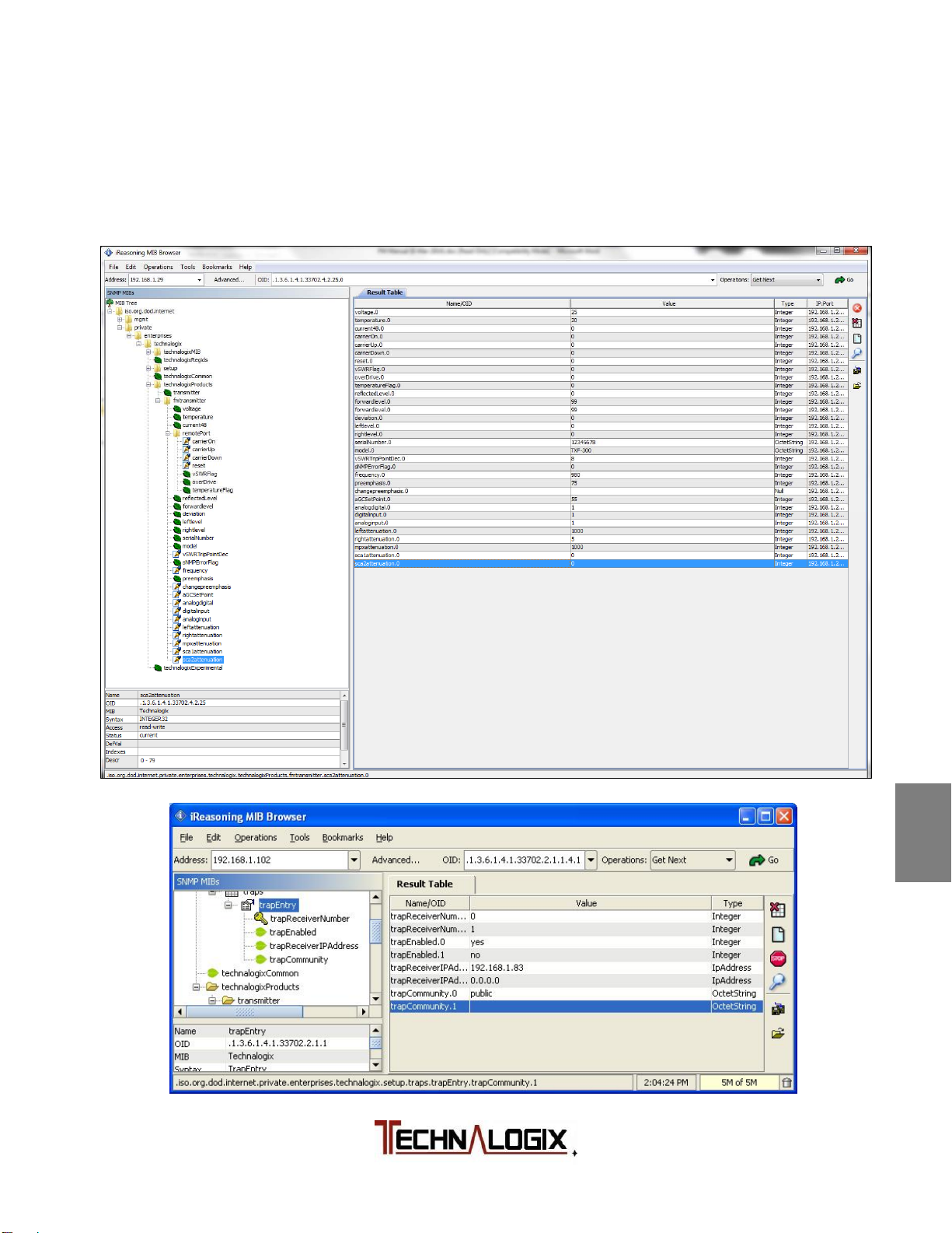
3.2.3 SNMP Traps
To enable the SNMP traps, within the MIB browser that you choose:
Set enable traps to 1 (or yes, depending on MIB browser).
Set the IP address to that of the receiving computer.
Set the community to one of the read communities set above.
1
2
3
4
5
6
7
8
Safeguards
Warranty
Terms and
Operation
Principle of
Installation
Operation
Control System
RF Components
Power Supply
9
Maintenance
10
Troubleshooting
Page 51
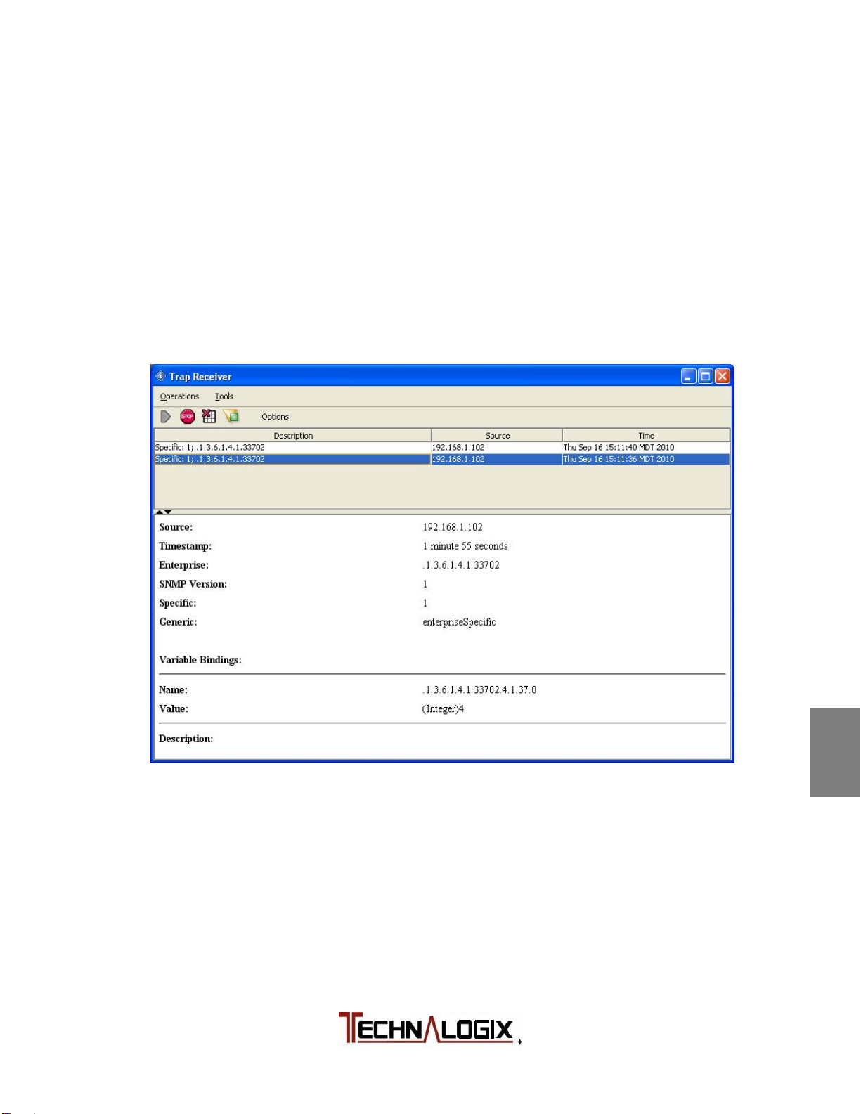
Ensure that your receiver’s port is set to 162
The system will generate a general trap on any error flag and send an 8-bit
value indicating the type of error, as follows:
Bit 0(LSB) Overdrive
Bit 1 High VSWR
Bit 2 High Temperature
Bit 3 High Speed Hardware Shutdown
Bit 4(MSB) High Input Level
As an example, the following is a screen shot of a high temperature fault
(Value 4).
1
2
3
4
Safeguards
Warranty
Terms and
Operation
Principle of
Installation
5
Operation
6
Control System
7
RF Components
8
Power Supply
9
Maintenance
10
Troubleshooting
Page 52
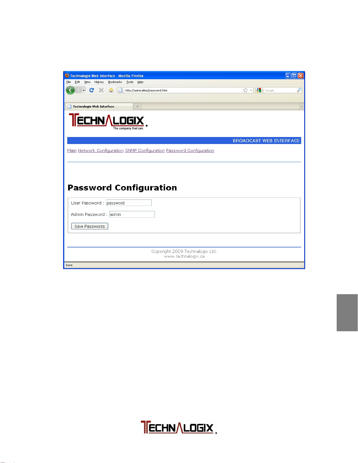
3.3 Password Configuration
This page allows the setting of the web browser’s User or Admin password,
as illustrated below.
The User account allows access only to the main page. The Admin account
allows access to the main and all the configuration pages.
Passwords are to be a maximum of 7 characters long. Don’t forget your
password. Resetting passwords isn’t as fun as it sounds and may cause loss
of all settings.
1
2
3
4
5
6
7
8
Safeguards
Warranty
Terms and
Operation
Principle of
Installation
Operation
Control System
RF Components
Power Supply
9
Maintenance
10
Troubleshooting
Page 53
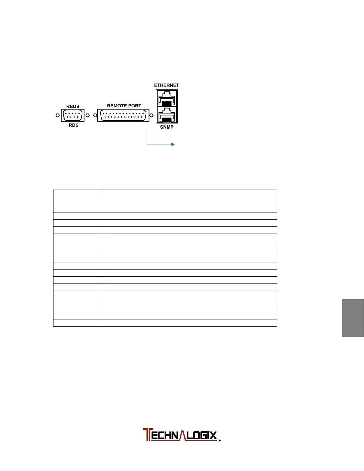
2
Remote Control (via DB25)
An additional option for remote control of the power amplifier/transmitter is
through the DB25 connector found on the back panel of the power
amplifier/transmitter, as illustrated below:
Attach a male DB25 cable
to this female connector
The overall functions of each pin on the Remote Port are indicated in the
following DB25 pinout:
Pin Number Description
1 Ground
2 Forward power sample1
3 Reflected power sample1
4 Carrier off2
5 Carrier on2
6 3 Increase carrier level 1%, if AGC on2
7 3 Decrease carrier level 1%, if AGC on2
8 Do not use
9 Reset
10 Do not use
11 High temperature flag2
12 High VSWR flag2
13 Amplifier overdriven flag2
14 Do not use
15 +3.3Vdc (for testing only, do not load)
16 Ground
17 Ground
18-25 Do not use
Notes: 1. Analog output with voltage ranging from 0 to 3.3Vdc.
2. Open collector configuration on RF 1.04 and later. On RF 1.04 and
later, ground to activate input control on inputs; ground indicates fault
occurrence on fault outputs. On RF 1.03 and earlier, the inputs are TTL
digital inputs, active on rising edge and the outputs are active high.
3. If AGC off, these pins turn on AGC to the current FWD level, +/- 1%.
In addition to the DB25 parallel data connector, the user may chose to remotely
control the RF amplifier/transmitter via an optional Ethernet web server or
through an optional Simple Network Managed Protocol (SNMP) interface,
described later in this section.
1
2
3
4
5
6
7
8
9
10
Safeguards
Warranty
Terms and
Operation
Principle of
Installation
Operation
Control System
RF Components
Power Supply
Maintenance
Troubleshooting
Page 54

RBDS and RDS
Radio Broadcast Data System (RBDS) is commonly used for FM broadcast in
North America, while the Radio Data System (RDS) is implemented in Europe. In
1998, the two standards were largely unified. Both systems are implemented as
standard features on Technalogix FM transmitters, including the control,
generator, and interface.
RDS uses a subcarrier to embed the FM signal with information. This can be
used to transmit time, station identification, programming information and more.
To control the RBDS/RDS connect to the DB9 on the back of the unit using a
RS232 connection. A USB-to-RS232 or Ethernet-to-RS232 convertor can be
used instead (not included with transmitter).
To interface with the RBDS/RDS you need to install the Magic RDS software.
Magic RDS software is found at http://www.pira.cz/rds/MagicRDS_Setup.exe.
General operating questions are answered here:
http://www.pira.cz/rds/show.asp?art=magic_rds_how_to.
The RBDS/RDS subcarrier level can be adjusted using R108 on the FM Exciter
1.01 circuit board. It should be set between 1.5 and 10% modulation. It is
recommended to turn to 0% if not RBDS/RDS is not being used to provide the
maximum available modulation for the audio signal.
1
2
3
4
5
6
Safeguards
Warranty
Terms and
Operation
Principle of
Installation
Operation
7
8
9
10
Control System
RF Components
Power Supply
Maintenance
Troubleshooting
Page 55
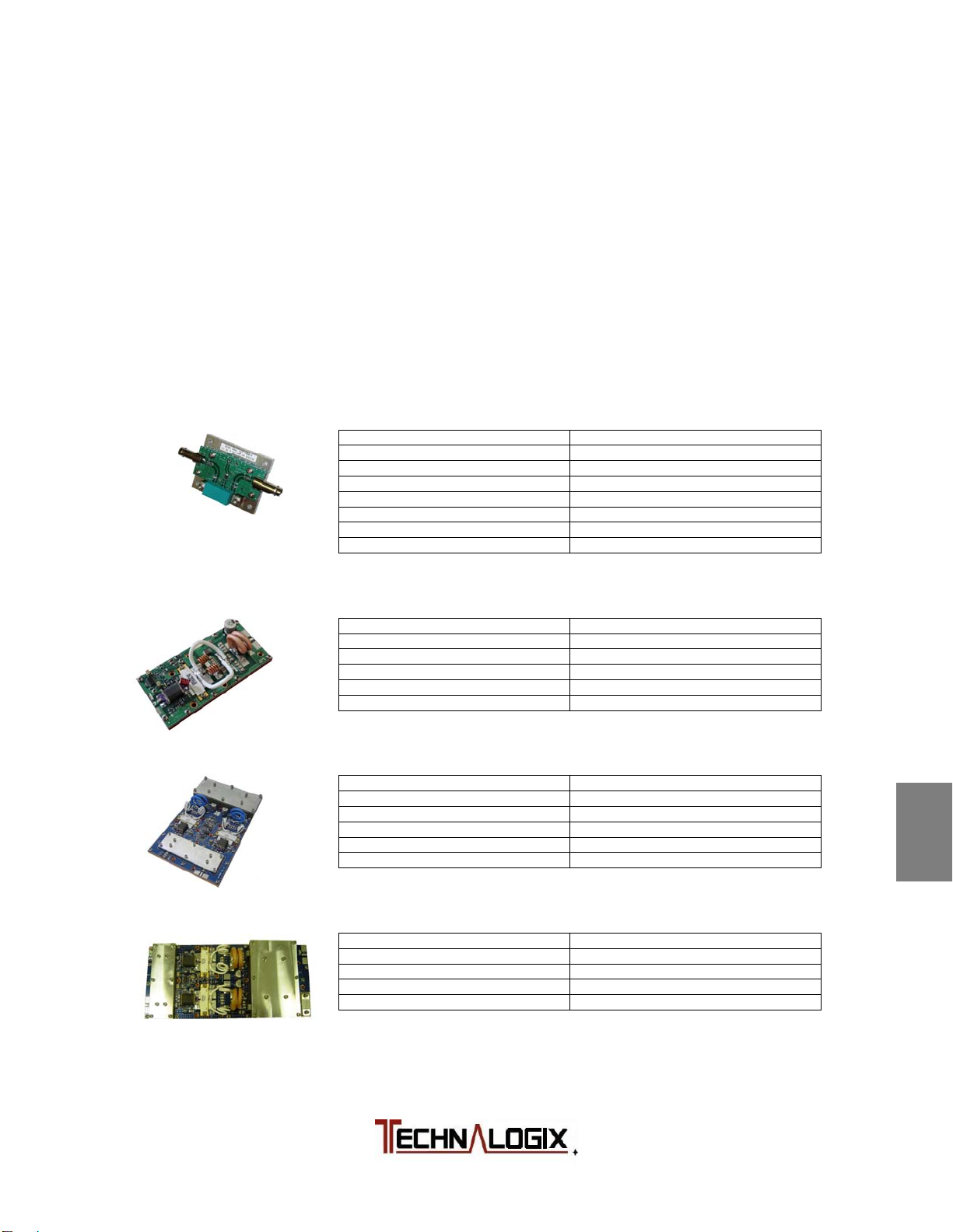
RF Components
FM Amplifier Pallets
The following is a summary of the typical FM amplifier pallets used in
Technalogix power amplifiers and transmitters out of the many pallets that have
been designed for production or custom applications. The exact bias and drain
currents of your system are found in the Final Inspection Report supplied in the
Quickstart package. Output power levels are absolute maximum levels.
Technalogix operates the pallets at reduced levels to improve performance and
increase reliability.
PB1A-50-1000-1042H
Typical gain 21.5 dB
P
max (NTSC) 1 W peak sync
out
P
max (8VSB) 0.4 W rms
out
P
max (DVB-T) 0.25 W
out
Pin max 15 dBm
Frequency 50 – 1000 MHz
ID max 0.47 Adc
VD 24 Vdc
PB1000F-88-108-188XR
Typical gain 25 dB
P
max (FM) 1050 W peak saturated at 50V
out
P
max (DVB-T) 400 W
out
Frequency 87.5 – 108.1 MHz
ID max 28 Adc
VD 48 Vdc
PB1200F-86-110-574-25
Typical gain 25 dB
P
max (FM) 1050 W peak saturated at 50V
out
P
max (DVB-T) 400 W
out
Frequency 87.5 – 108.1 MHz
ID max 28 Adc
VD 48 Vdc
PB1200F-86-110-574-49
Minimum 25 dB
P
max (FM) 1200 W peak saturated at 50V
out
Frequency 87.5 – 108.1 MHz
ID max 32-36 Adc
VD 32-50 Vdc
1
2
3
4
5
6
7
8
9
10
Safeguards
Warranty
Terms and
Operation
Principle of
Installation
Operation
Control System
RF Components
Power Supply
Maintenance
Troubleshooting
Page 56
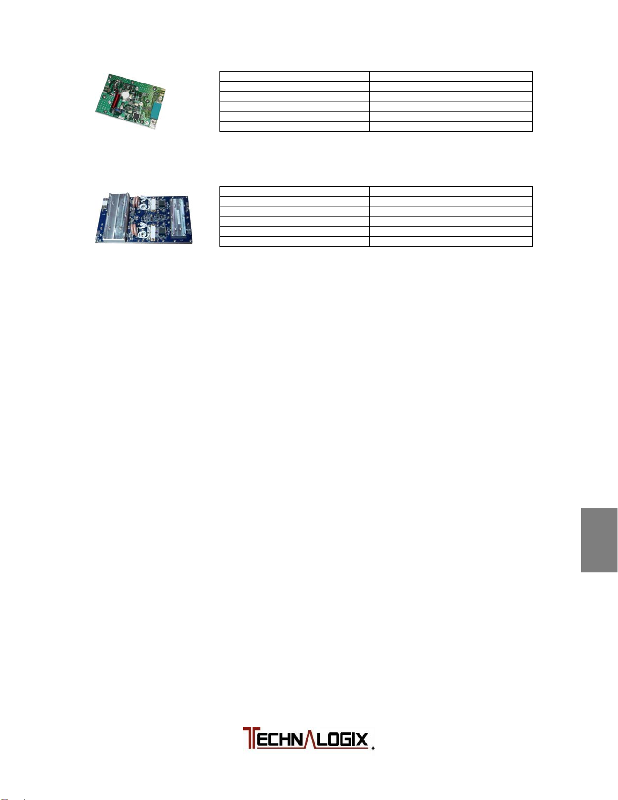
PB25C-86-110-xxx
PB1200C-86-110-574
Typical gain 40 dB
P
max (8VSB) 25 W rms
out
Frequency 88 – 108 MHz
Pin max 10 dBm
ID max 1.6 Adc
VD 28 Vdc
Typical gain 25 dB
P
min (FM) 1125 W (w/ 3.5 W input)
out
Frequency 86 – 110 MHz
Pin max 10 dBm
ID typ 32 - 36 Adc
VD 32 - 50 Vdc
1
2
3
4
Safeguards
Warranty
Terms and
Operation
Principle of
Installation
5
Operation
6
Control System
7
RF Components
8
Power Supply
9
Maintenance
10
Troubleshooting
Page 57
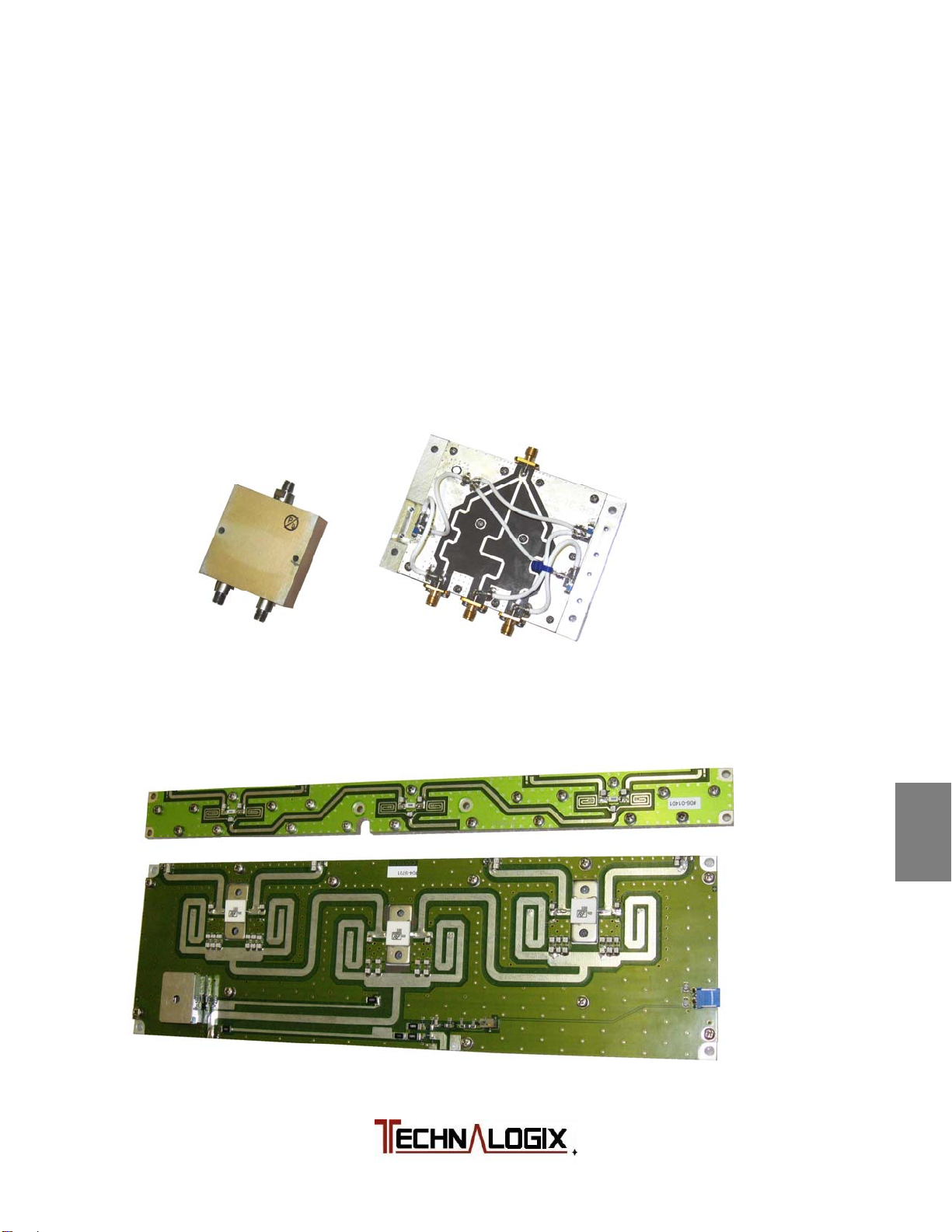
Splitter/Combiner
If used, the splitter and combiner are used to split the RF signal into, and
combine the amplified RF signal out of the final amplifier pallets, within an
amplifier/transmitter enclosure. The splitter and combiner can be 2-, 3-, or 4-way
depending on how many finals pallets are used. Most designs are based on the
simple isolated Wilkinson combiner design. Due to its electrical and mechanical
symmetry, the Wilkinson design’s performance over moderate bandwidths is
superior to other types.
2-, 3-Way:
4-Way:
1
2
3
4
5
6
7
8
9
10
Safeguards
Warranty
Terms and
Operation
Principle of
Installation
Operation
Control System
RF Components
Power Supply
Maintenance
Troubleshooting
Page 58
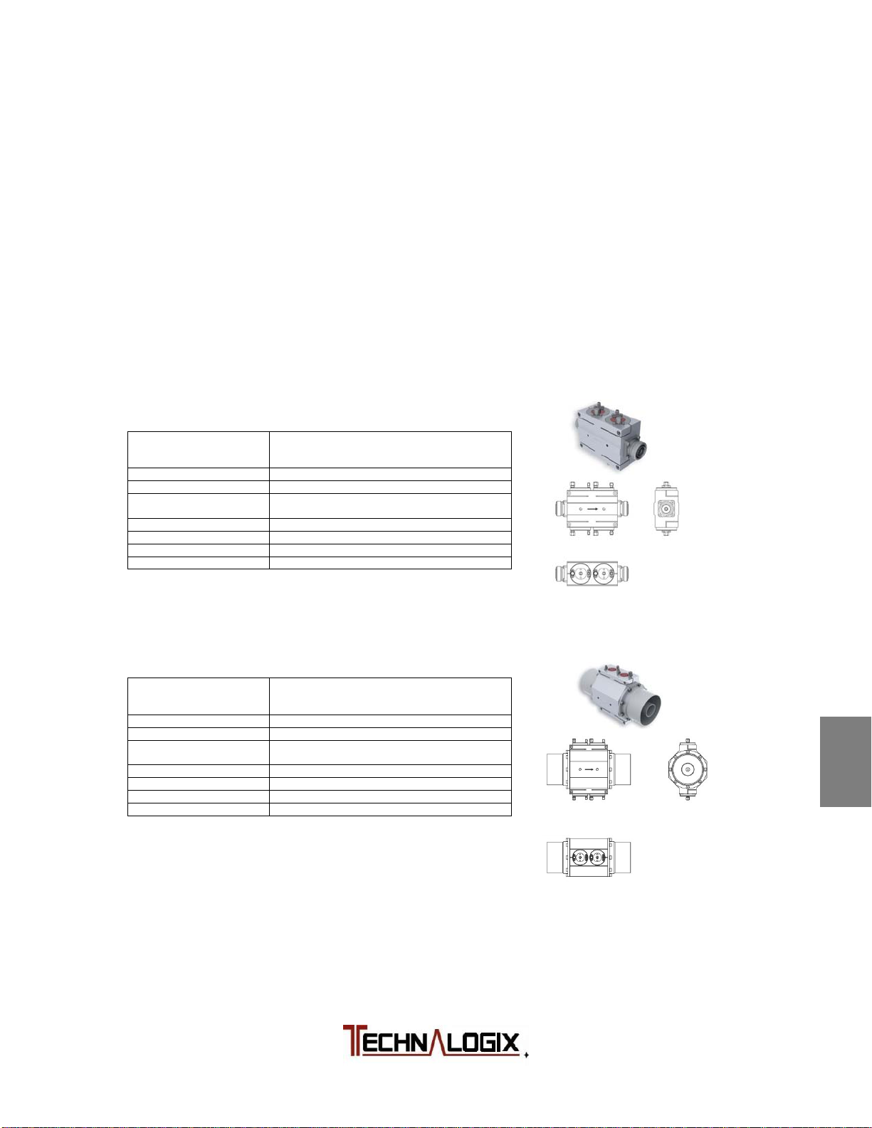
r
g
r
g
Directional Coupler
The dual directional coupler provides RF samples proportional to forward and
reflected RF power to be converted to DC voltages for monitoring. These analog
voltages are converted for processing using analog-to-digital converters and
provide the control system with valuable data for monitoring purposes. Output
power should be set following the operating procedure found elsewhere in this
manual. The directional coupler uses Type N connectors on lower power systems
and 7-16 DIN connectors are used for increased power handling capability. Other
connectors are available upon request – this connector is typically the RF output
connector on the back panel of the enclosure. On higher power systems, high
power handling connectors are used, especially in the overall output combiner.
On lower power systems, the coupler is typically based on microstrip architecture
on the exciter circuit board.
Frequency Range 41 – 100 MHz (option A)
Max Output Powe
Couplin
-36 to -60 dB (on any channel)
Coupling variation < ±0.15 dB 162 –254 MHz
Return Loss > 30 dB (VSWR < 1.07)
Directivity > 30 dB
Environmental Conditions -5 to +55 °C (+23 to +131 °F)
Connectors N, 7-16DIN, EIA 7/8” (dependent on power level)
2 kW DTV (3 kW ATV)
Frequency Range 41 – 100 MHz (option A)
Max Output Powe
Couplin
-48 to -72 dB (on any channel)
Coupling variation < ±0.15 dB 162 –254 MHz
Return Loss > 30 dB (VSWR < 1.07)
Directivity > 30 dB
Environmental Conditions -5 to +55 °C (+23 to +131 °F)
Connectors EIA 1-5/8” or 3-1/8”(dependent on power level)
20 kW DTV (30 kW ATV)
162 – 254 MHz (option B)
470 – 862 MHz (option C)
< ±0.15 dB 470 – 862 MHz
162 – 254 MHz (option B)
470 – 862 MHz (option C)
< ±0.15 dB 470 – 862 MHz
1
2
3
4
5
6
7
8
9
10
Safeguards
Warranty
Terms and
Operation
Principle of
Installation
Operation
Control System
RF Components
Power Supply
Maintenance
Troubleshooting
Page 59
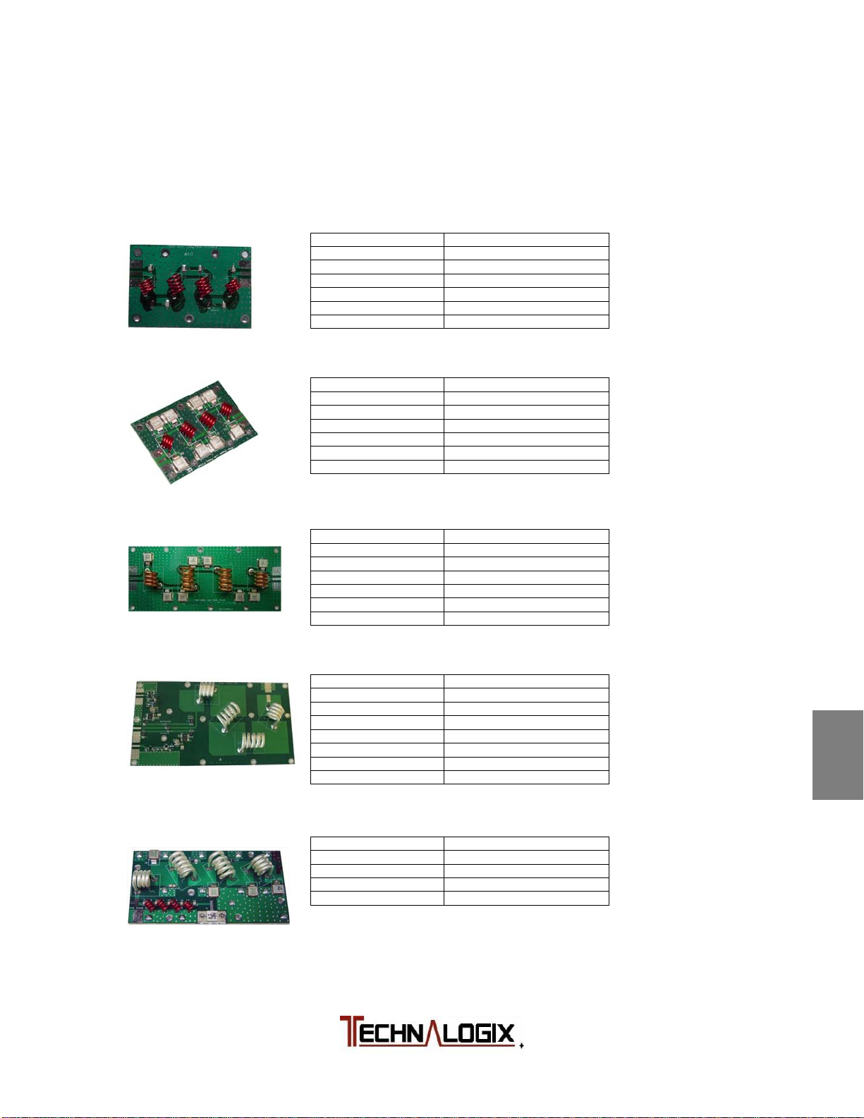
Filter
Our passive 50 ohm lowpass FM filters reject (and in some cases, absorb)
spurious and harmonic output products and passes the modulated FM output
carrier to the antenna or load.
150W LPF, no coupler
Frequency Range 86 – 110 MHz
Input Power (max) 150 W continuous
Insertion Loss (max) < 0.3 dB
Insertion Loss (typ) < 0.25 dB
Return Loss (max) > 25 dB
Return Loss (typ) > 28 dB
Rejection at 176 MHz > -45 dB
250W LPF, no coupler
Frequency Range 86 – 110 MHz
Input Power (max) 250 W continuous
Insertion Loss (max) < 0.3 dB
Insertion Loss (typ) < 0.25 dB
Return Loss (max) > 25 dB
Return Loss (typ) > 28 dB
Rejection at 176 MHz > -45 dB
800W LPF, no coupler
Frequency Range 86 – 110 MHz
Input Power (max) 800 W continuous
Insertion Loss (max) < 0.25 dB
Insertion Loss (typ) < 0.2 dB
Return Loss (max) > 25 dB
Return Loss (typ) > 28 dB
Rejection at 176 MHz > -60 dB
1,200W LPF, with coupler
Frequency Range 86 – 110 MHz
Input Power (max) 1,200 W continuous
Insertion Loss (max) < 0.2 dB
Insertion Loss (typ) < 0.15 dB
Return Loss (max) > 25 dB
Return Loss (typ) > 30 dB
Rejection at 176 MHz > -47 dB
Directivity (min) 25 dB
1,500W LPF, absorbing, no coupler
Frequency Range 87.5 - 108 MHz
Input Power (max) 1,500 W continuous
Insertion Loss (typ) < 0.1 dB
Return Loss (typ) > 30 dB
Rejection at 176 MHz > 10 dB return loss
1
2
3
4
5
6
7
8
9
10
Safeguards
Warranty
Terms and
Operation
Principle of
Installation
Operation
Control System
RF Components
Power Supply
Maintenance
Troubleshooting
Page 60
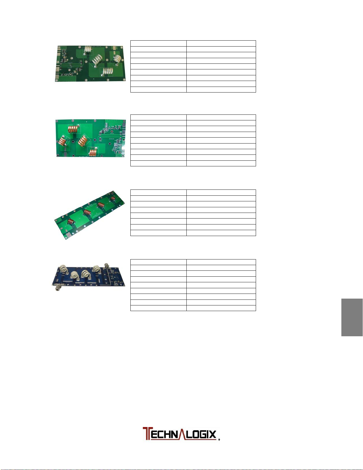
1,500W LPF, with coupler
Frequency Range 86 – 110 MHz
Input Power (max) 1,500 W continuous
Order 9th order Chebyshev
Insertion Loss (max) < 0.2 dB
Insertion Loss (typ) < 0.15 dB
Return Loss (max) > 25 dB
Return Loss (typ) > 30 dB
Rejection at 176 MHz > -47 dB
Directivity (min) 20 dB
1,500W LPF, with -50dB coupler
Frequency Range 86 – 110 MHz
Input Power (max) 1,500 W continuous
Order 9th order Chebyshev
Insertion Loss (max) < 0.12 dB
Insertion Loss (typ) < 0.1 dB
Return Loss (max) > 28 dB
Return Loss (typ) > 33 dB
Rejection at 176 MHz > -47 dB
Directivity (min) 20 dB
2,000W LPF, no coupler
Frequency Range 86 – 110 MHz
Input Power (max) 2,000 W continuous
Order 9th order Chebyshev
Insertion Loss (max) < 0.12 dB
Insertion Loss (typ) < 0.1 dB
Return Loss (max) > 23 dB
Return Loss (typ) > 25 dB
Rejection at 176 MHz > -45 dB
3,600W LPF, with coupler
Frequency Range MHz
Input Power (max) 3,600 W continuous
Order 9th order Chebyshev
Insertion Loss (max) < dB
Insertion Loss (typ) < dB
Return Loss (max) > dB
Return Loss (typ) > dB
Rejection at 176 MHz > dB
Directivity (min) > - dB
1
2
3
4
5
6
7
8
9
Safeguards
Warranty
Terms and
Operation
Principle of
Installation
Operation
Control System
RF Components
Power Supply
Maintenance
10
Troubleshooting
Page 61

Power Supply Components
Switching AC-DC power supplies are used to power the amplifier pallets, the
control circuits, and all of the fans. The DC system voltage is set at either 24, 30,
or 48Vdc nominally, depending on the system. All fans run off this same DC
supply. The specific DC system voltage is found in the Final Inspection Report,
and the model and number of power supplies, is documented in the Block
Diagram supplied in the Quickstart package.
AC is fed into the power supply enclosure via a filtered AC entry and then
through a circuit breaker/switch. Specific AC current draw is documented in the
Final Inspection Report supplied in the Quickstart package. AC is then converted
to DC using one or more AC-DC switching power supplies.
The following is the switching power supply data sheet(s) used to convert the AC
to DC for the internal amplifier or transmitter components.
1
2
3
4
Safeguards
Warranty
Terms and
Operation
Principle of
Installation
5
Operation
6
Control System
7
RF Components
8
Power Supply
9
Maintenance
10
Troubleshooting
Page 62
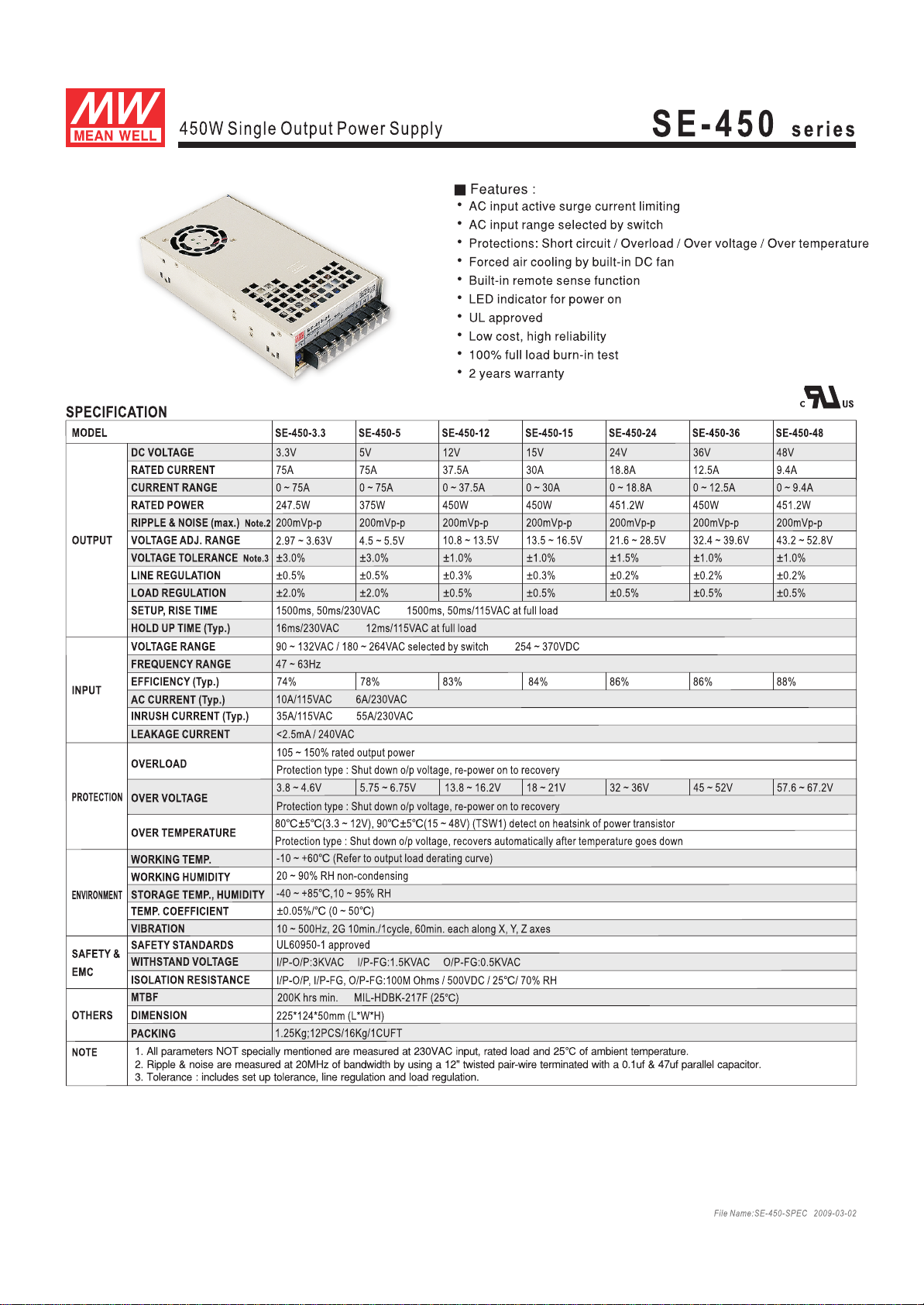
Page 63
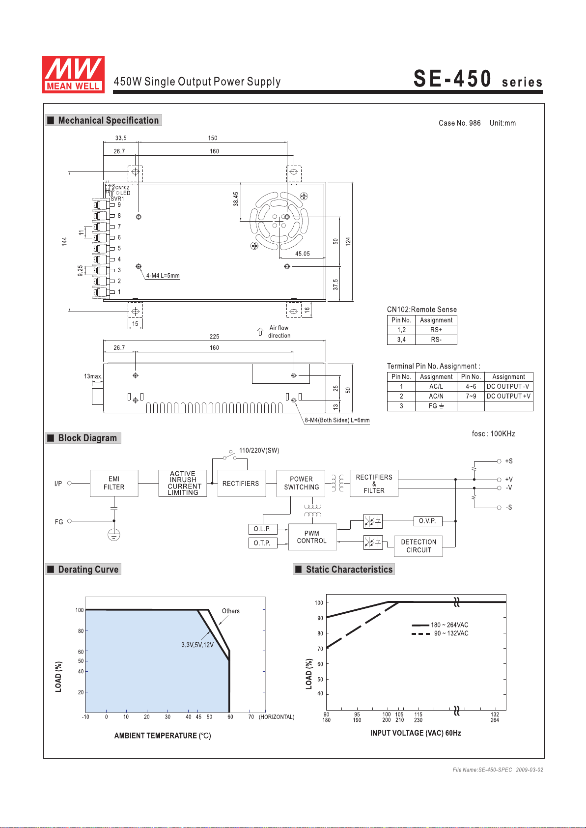
Page 64
Maintenance
If your unit employs a filter on the air inlet for the fans, the filter should be cleaned
every 30 days. If the equipment is operated in a severe dust environment, the
filters on the inlet fan may need to be cleaned more regularly. Turn the system off
and unplug all of the AC inlet cords. The filter can be lifted off the fan and
cleaned using an air compressor at low pressure. While the filter is out, clean the
fan blades themselves with a small brush. The fans themselves do not need
lubrication.
The interior of the cabinets should be cleaned and inspected annually. Turn the
system off and unplug all of the AC inlet cords. Remove the top lid by unscrewing
the 6-32 machine screws.
Use extreme caution when working near the AC input terminal. The
power amplifier/transmitter and power supply store hazardous
capacitances and voltages.
Using either compressed air or a brush with soft bristles, loosen accumulated
dust and dirt and then vacuum the interior of the cabinet. Complete a visual
inspection of the interior, making sure there are no loose connections or
discolorations on any components from heat. Nothing inside the power amplifier
or transmitter enclosure exceeds a temperature that is not comfortable to the
touch under normal operating conditions (unless it is RF!), so any signs of
discoloration indicate potential damage.
All modular components inside the enclosure are attached to aluminium
mounting plates for easy removal and replacement. Ensure that plates are
secured and the mounting hardware is tight.
1
2
3
4
5
6
7
Safeguards
Warranty
Terms and
Operation
Principle of
Installation
Operation
Control System
RF Components
8
Power Supply
9
Maintenance
10
Troubleshooting
Page 65

Troubleshooting
The first and most important aspect of troubleshooting anything is to be
systematic. Note where you have looked and what you found.
Look first for the obvious.
Make a physical inspection of the entire facility. Are all necessary
connections properly made? Do you see any signs of obvious damage within
the equipment?
Is the AC power ‘ON’ to the site and the equipment? (Check fuses and circuit
breakers if necessary.)
Are all the switches in the correct operating position?
Is the input signal present and at the correct level?
Check display readings for presence of forward and reflected power and DC
supply levels.
The following flowcharts are an aid in determining the fault if some aspect of the
system is not operating.
1
2
3
4
5
Safeguards
Warranty
Terms and
Operation
Principle of
Installation
Operation
6
7
8
9
10
Control System
RF Components
Power Supply
Maintenance
Troubleshooting
Page 66
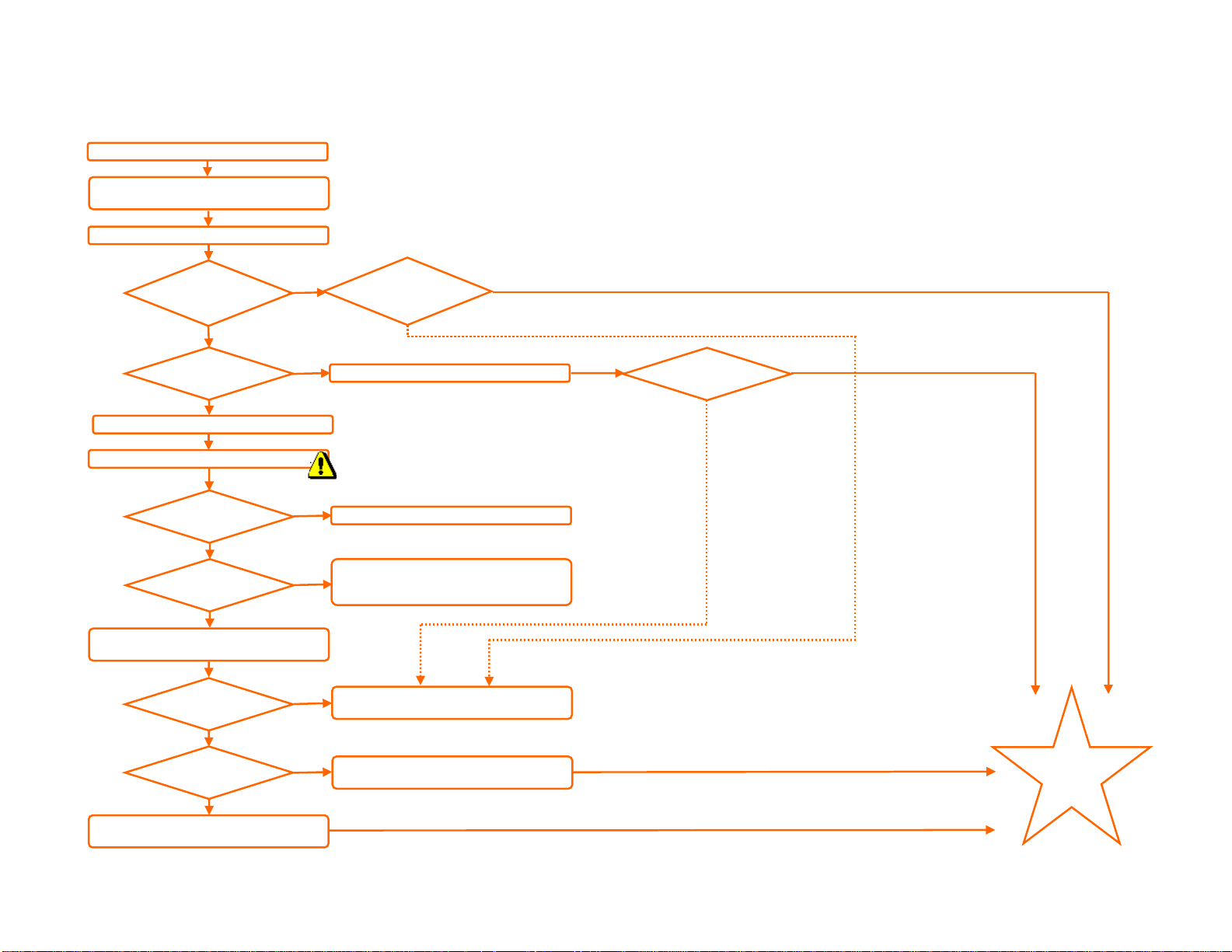
Properly terminate PA into 50ohm load.
(
O
p
)
Apply proper AC power to back panel
check if 110V or220V).
Turn on AC rocker switch on back panel.
AC-DC Power Supply (PSU) Troubleshooting
Display
on?
NO
AC breaker tripped?
NO
Turn off power from back panel.
Remove lid of enclosure with power supply.
AC voltage present
on PSU in
DC voltage present
on PSU output?
Disconnect DC loads (tape off so they do not
short out
to see if DC output loaded down.
Proper DC voltage
on PSU output?
shutdown mode?
Remove shutdown conditions and
reset the PSU.
Is PSU in
YES
ut?
YES
NO
N
YES
YES
NO
YES
YES
NO
DC
voltage on
display
correct?
NO
Reset circuit breaker on back panel.
DANGEROUS
VOLTAGES INSIDE!
Faulty AC connection, entry, switch, or breaker.
Screen not displaying, but DC PSU
voltage okay. Troubleshoot control
system.
Pallet, fan, or control system loading PSU down.
Troubleshoot control system or RF signal path.
Bad PSU - magic smoke released.
Replace PSU.
YES
Display and
PSU come
back on?
YES
NO
PSU is
operating
correctly.
Last Updated: 12-Jul-2011
Page 67
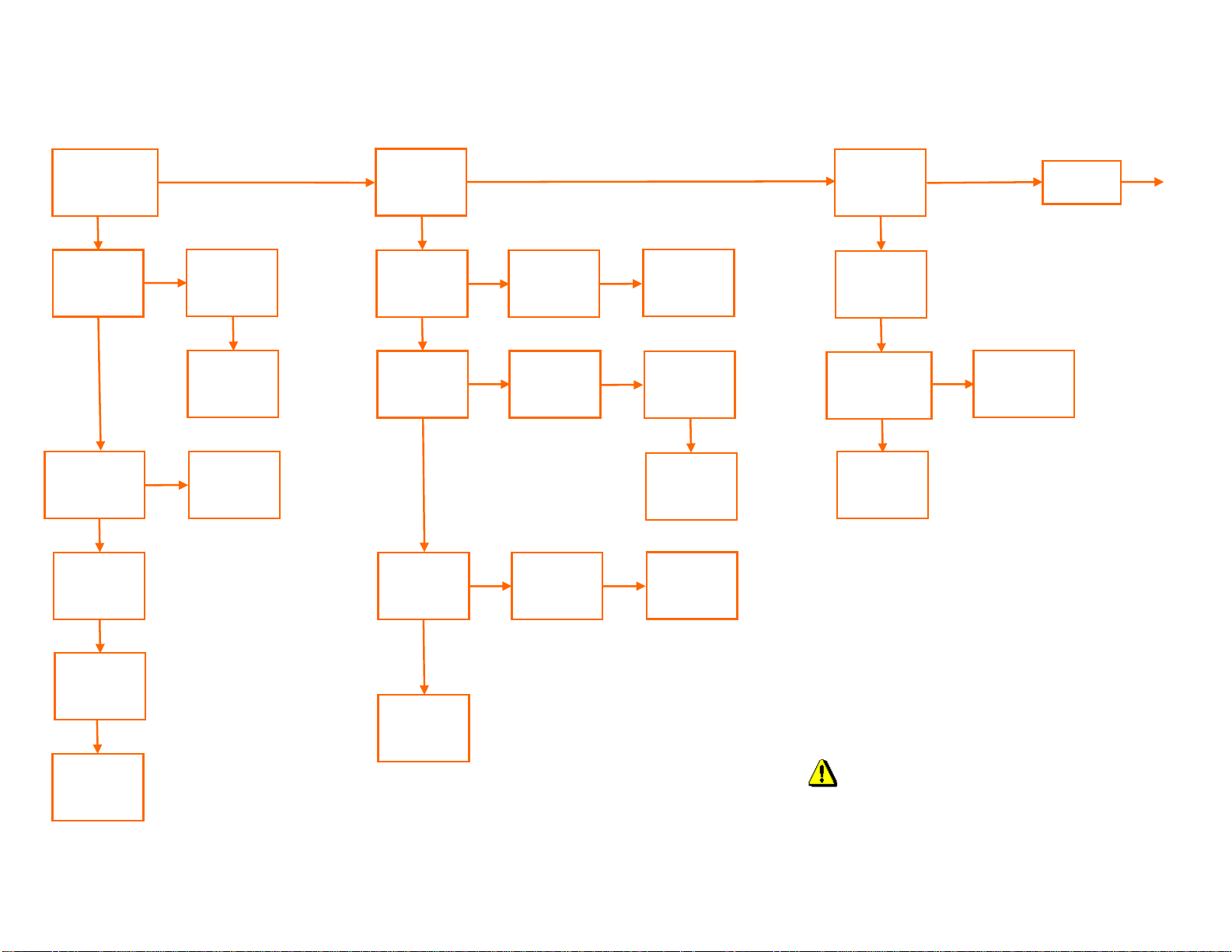
Front panel
membrane
Buttons (if used)
functioning?
NO
Alternative
button inputs
on remote
port working?
NO
AC-DC power
supply output
at proper
voltage?
YES
PSU wiring
inputs to
control PCBs
secure?
YES
Bad
membrane
switch or
control PCB
Contact
Technalogix
for further
information
YES
NO
YES
Membrane
connected
properly to
PCB?
YES
Bad / loose
membrane
connector /
wiring
Follow power
supply troubleshooting guide
Control System (Adrenaline) Troubleshooting (1 of 2)
Display
showing text
and data
accurately?
NO
Is text /
graphics
readable?
YES
FWD and
RFL display
data
accurate?
YES
YES
NO
NO
Display pins /
connector
seated
properly?
Type of
modulation,
A/V ratio, etc
correct?
YES
YES
Replace preprogrammed
touchscreen
or display
DC or RF
from dir.
coupler
correct?
Contact
Technalogix
for further
information
Remote port
working
correctly?
Check cable
that mates to
DB25 panel
connector
Is external
equipment
loading down 5V
or 3V on port?
Contact
Technalogix
for further
information
Power supply
display data
accurate?
YES
NO
RF or DC
Distribution
PCB issue
Contact
Technalogix
for further
information
Contact
Technalogix
for further
information
DANGEROUS VOLTAGES
INSIDE ENCLOSURE!
NO
NO
YES
YES
Power external
equipment from
dedicated
power supply
Goto page
2 of 2
Last Updated: 29-Aug-2011
Page 68
Ethernet
interface
functioning?
YES
Control System (Adrenaline) Troubleshooting (2 of 2)
SNMP
interface
functioning?
YES
Communication
between PCBs
working (CAN)?
Display Interface
orange S/W LED
flashing?
Is FWD, RFL, or
DC voltage
displayed on
screen?
DANGEROUS VOLTAGES
INSIDE ENCLOSURE!
NO
YES
NO
YES
Contact
Technalogix
for any
issues not
listed
Display Int. not
communicating with
RF PCB. Check
CAT5 cables
Contact
Technalogix for
any issues not
listed
Last Updated: 29-Aug-2011
Page 69

Thank you
for choosing
Technalogix Ltd.
If there is anything we can do to help in your success, please do not hesitate to
contact us. We also welcome suggestions for product improvements or feature
enhancements, as long as it is not a built in coffee maker.
1
2
3
4
5
Safeguards
Warranty
Terms and
Operation
Principle of
Installation
Operation
6
7
8
9
10
Control System
RF Components
Power Supply
Maintenance
Troubleshooting
 Loading...