

Page 1
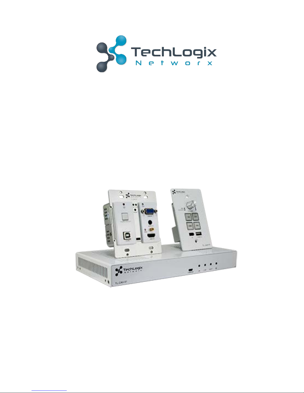
User Manual
TL-CAV-01-HDV
Multi-function AV distribution system
All Rights Reserved
Version: TL-CAV-01-HDV_170905
Page 2

TL-CAV-01-HDV User Manual
www.tlnetworx.com
Preface
Read this user manual carefully before using this product. Pictures shown in this manual
is for reference only, different model and specifications are subject to real product.
This manual is only for operation instruction only, not for any maintenance usage.
Trademarks
Product model and logo are trademarks. Any other trademarks mentioned in this manual
are acknowledged as the properties of the trademark owner. No part of this publication
may be copied or reproduced without the prior written consent.
FCC Statement
This equipment generates, uses and can radiate radio frequency energy and, if not
installed and used in accordance with the instructions, may cause harmful interference
to radio communications. It has been tested and found to comply with the limits for a
Class A digital device, pursuant to part 15 of the FCC Rules. These limits are designed to
provide reasonable protection against harmful interference in a commercial installation.
Operation of this equipment in a residential area is likely to cause interference, in which
case the user at their own expense will be required to take whatever measures may be
necessary to correct the interference
Any changes or modifications not expressly approved by the manufacture would void
the user’s authority to operate the equipment.
Page 3

TL-CAV-01-HDV User Manual
www.tlnetworx.com
SAFETY PRECAUTIONS
To insure the best from the product, please read all instructions carefully before using
the device. Save this manual for further reference.
l Unpack the equipment carefully and save the original box and packing material for
possible future shipment
l Follow basic safety precautions to reduce the risk of fire, electrical shock and injury
to persons.
l Do not dismantle the housing or modify the module. It may result in electrical shock
or burn.
l Using supplies or parts not meeting the products’ specifications may cause damage,
deterioration or malfunction.
l Refer all servicing to qualified service personnel.
l To prevent fire or shock hazard, do not expose the unit to rain, moisture or install
this product near water.
l Do not put any heavy items on the extension cable in case of extrusion.
l Do not remove the housing of the device as opening or removing housing may
expose you to dangerous voltage or other hazards.
l Install the device in a place with fine ventilation to avoid damage caused by
overheat.
l Keep the module away from liquids.
l Spillage into the housing may result in fire, electrical shock, or equipment damage. If
an object or liquid falls or spills on to the housing, unplug the module immediately.
l Do not twist or pull by force ends of the optical cable. It can cause malfunction.
l Do not use liquid or aerosol cleaners to clean this unit. Always unplug the power to
the device before cleaning.
l Unplug the power cord when left unused for a long period of time.
l Information on disposal for scrapped devices: do not burn or mix with general
household waste, please treat them as normal electrical wastes.
Page 4

TL-CAV-01-HDV User Manual
www.tlnetworx.com
Contents
1. Introduction ................................................................................................................. 1!
1.1 Brief Introduction ............................................................................................... 1!
1.2 Features ............................................................................................................. 1!
1.3 Package List ........................................................................................................ 2!
2. Panel Description ......................................................................................................... 3!
2.1 Transmitter ......................................................................................................... 3!
2.2 Receiver .............................................................................................................. 4!
2.3 Control Panel ...................................................................................................... 7!
3. System Connection ...................................................................................................... 9!
3.1 Usage Precautions .............................................................................................. 9!
3.2 System Diagram .................................................................................................. 9!
3.3 Connection Procedure ........................................................................................ 9!
3.4 PoC Solution ..................................................................................................... 10!
3.5 Typical Application ........................................................................................... 11 !
4. System Operation ...................................................................................................... 12!
4.1 IR Learning Function ......................................................................................... 12!
4.2 Front Panel Button Control .............................................................................. 12!
4.3 USB Signal Return ............................................................................................ 13!
4.4 RS232 control ................................................................................................... 14!
4.5 IR control .......................................................................................................... 14!
4.6 Web-based GUI Control ................................................................................... 16!
4.6.1 Control Menu ......................................................................................... 16!
4.6.2 Setting Menu .......................................................................................... 17!
4.6.3 Command Menu ..................................................................................... 19!
4.6.4 Network Menu ....................................................................................... 20!
4.6.5 GUI update ............................................................................................. 20!
4.7 Copy and load configuration data ..................................................................... 21!
4.7.1 Copy Configuration Data ........................................................................ 21!
4.7.2 Load configuration data .......................................................................... 21!
5. Specification .............................................................................................................. 22!
Page 5

TL-CAV-01-HDV User Manual
www.tlnetworx.com
5.1 Transmitter ....................................................................................................... 22!
5.2 Receiver ............................................................................................................ 23!
5.3 Control Panel .................................................................................................... 24!
6. Panel Drawing ............................................................................................................ 25!
6.1 Transmitter ....................................................................................................... 25!
6.2 Receiver ............................................................................................................ 25!
6.3 Control Panel .................................................................................................... 26!
7. Troubleshooting & Maintenance ................................................................................ 27!
8. After-sales Service ..................................................................................................... 29!
Page 6

1
TL-CAV-01-HDV User Manual
www.tlnetworx.com
1. Introduction
1.1 Brief Introduction
TL-CAV-01-HDV is a multi-function AV distribution system, which includes a wall plate
HDBaseT transmitter, HDBaseT receiver with built-in audio amplifier and control panel.
It is designed to provide HDMI and VGA video switching, system control, video
extension and analog audio amplification in a convenient kit.
Transmitter provides one HDMI and one VGA with analog audio signal inputs, which
support HDCP 1.4 and can be switched automatically or manually. It transmits the
HDMI signal to the receiver via shielded solid core Cat 5e or greater cable, and the
maximum distance can be up to 30m at 1920x1200 @ 60 Hz.
The receiver features a microphone input, analog audio output, 2x20 at 4 ohms speaker
output, and IR or RS232 control to the display in addition to the HDMI output. A USB
port on the receiver will transmit interactive display connections to the transmitter.
The control panel is an easy-to-use control device for huddle rooms, classrooms and
boardrooms. It can power on and off the display, select between the two inputs, and
separately adjust and mute the source and microphone audio.
TL-CAV-01-HDV supports simultaneous panel button and web-based GUI control.
Moreover, with its PoC solution, a single power point on the receiver provides power to
the transmitter and control panel over the Cat cables.
1.2 Features
l Switch between HDMI and VGA signal inputs
l HDMI output resolution up to 1920x1200 @ 60 Hz
l VGA input with scaler
l Supports HDCP1.4
l Supports MIC input
l 2x20 watts @ 4 ohms amplifier output.
l Control Panel with IR Learning
l Convenient configuration copying for multiple installations
l Supports UPNP
l Remote audio muting
l Interactive display USB pass-through
l Web GUI control option that works on all devices
Page 7

2
TL-CAV-01-HDV User Manual
www.tlnetworx.com
1.3 Package List
l 1 x Transmitter
l 1 x Receiver
l 1 x Control Panel
l 1 x Power adapter (DC 24V 2.71 A)
l 2 x Mounting ears (for Receiver)
l 4 x Screws (for installing mounting ears)
l 4 x Rubber feet (for Receiver)
l 1 x Pluggable Terminal Block (4-pin block, used for 2x20Watt@4Ω port)
l 3 x Pluggable Terminal Block (3-pin blocks, used for LINE OUT or RS232 port)
l 1 x Pluggable Terminal Block (2-pin block, used for REMOTE MUTE port)
l 1 x IR emitter
l 1 x USB control cable (USB-A to USB-B)
l 1 x White face plate
l 1 x User Manual
Notes:If you find any defective or missing parts, please contact your local dealer.
Page 8
3
TL-CAV-01-HDV User Manual
www.tlnetworx.com
2. Panel Description
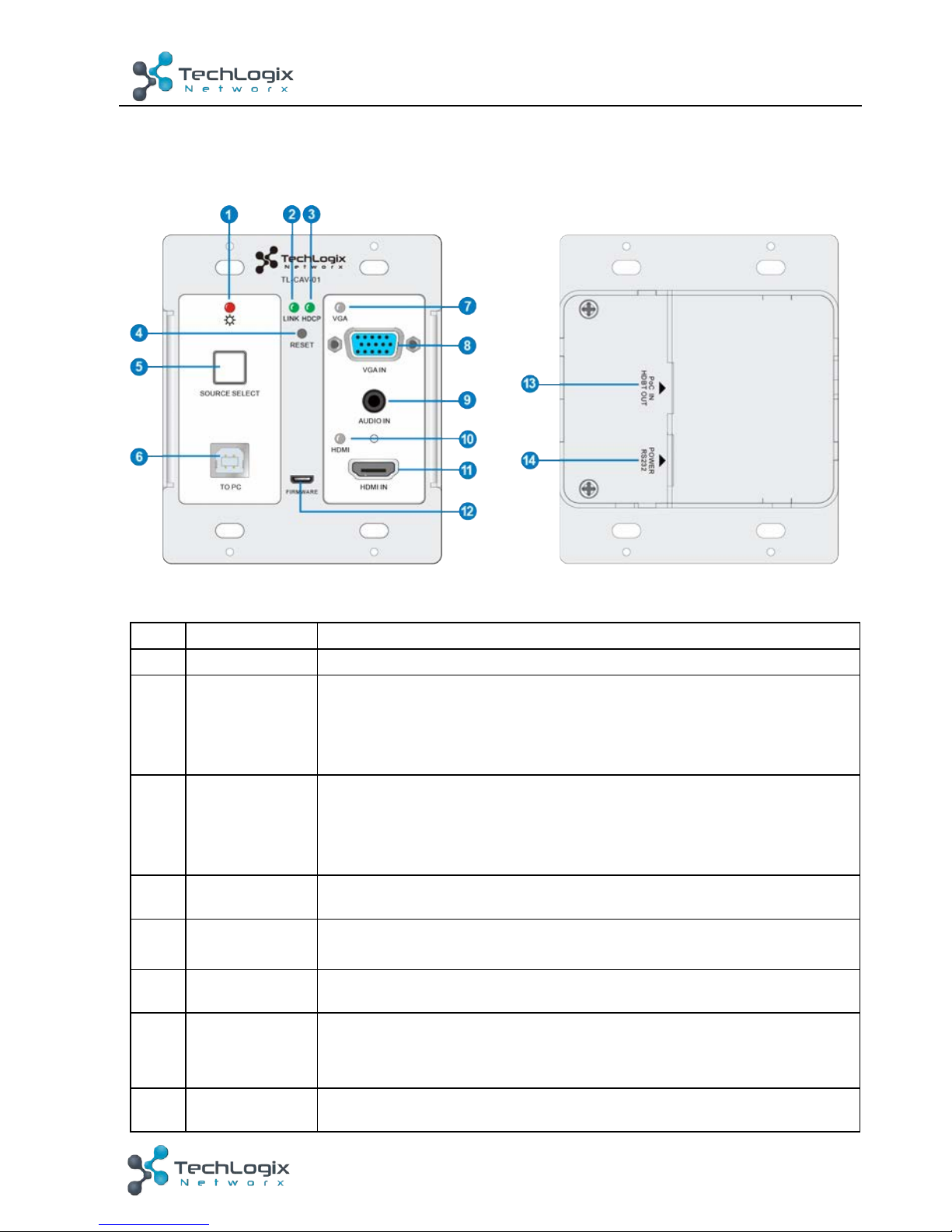
2.1 Transmitter
Figure 2-1 Transmitter
No.
Name
Description
①
Power
Turns red when power is connected
②
Link
HDBT Link status indicator:
ü OFF: No Link
ü GREEN: Link successful
ü Blinking GREEN: Link abnormal
③
HDCP
HDCP compliance indicator:
ü OFF: No HDMI traffic (no picture)
ü GREEN: Traffic with HDCP
ü Blinking GREEN: Traffic without HDCP
④
RESET
Press this button to reboot Transmitter.
⑤
SOURCE
SELECT
Alternates between HDMI IN 1 and HDMI IN 2. Press and hold
for 3 seconds to enable Auto switch mode.
⑥
To PC
Connect PC to transmit USB control signal from the display.
⑦
VGA IN
indicator
ü OFF: No VGA signal traffic
ü YELLOW: VGA signal traffic
ü GREEN: VGA IN is chosen as input source.
⑧
VGA IN
VGA input
Page 9
4
TL-CAV-01-HDV User Manual
www.tlnetworx.com
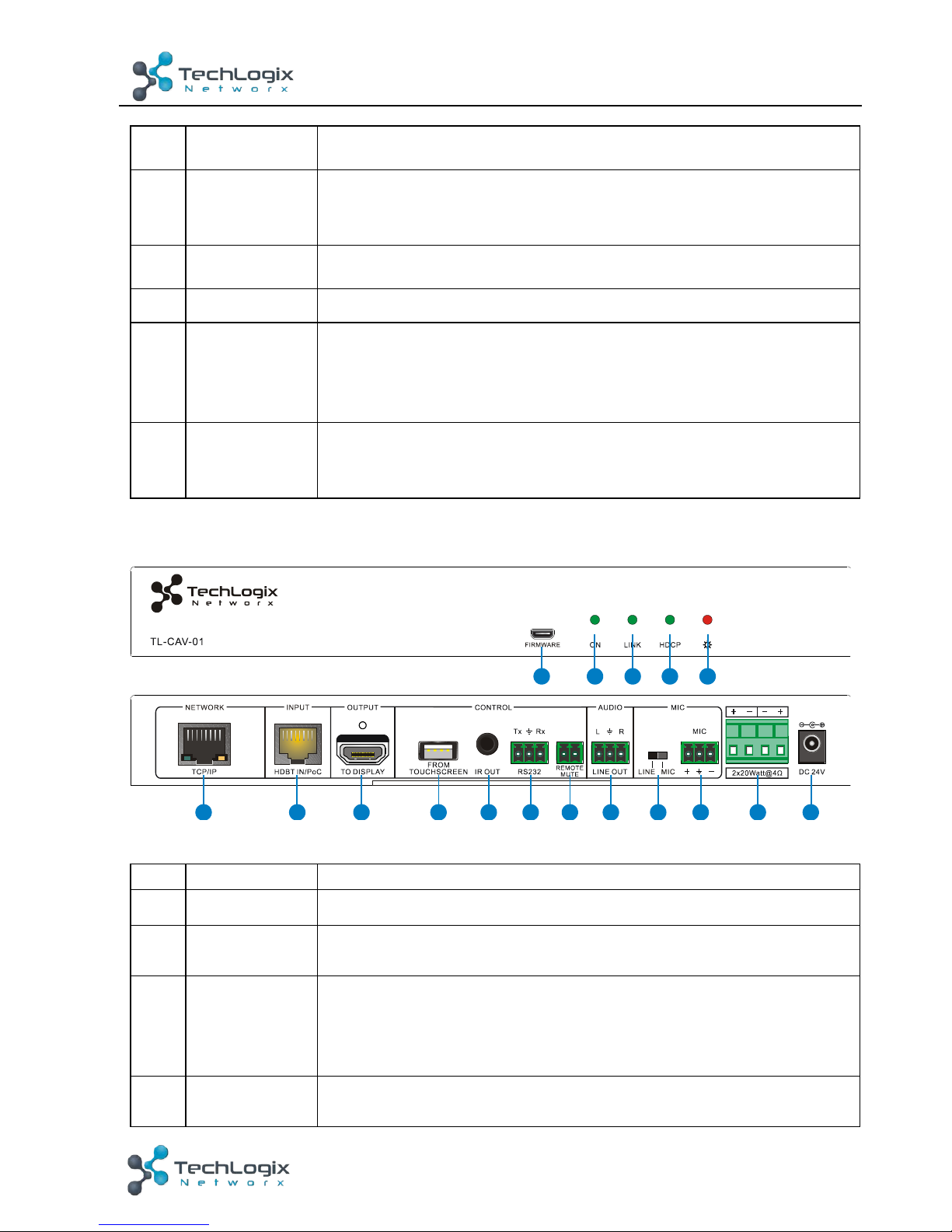
⑨
AUDIO IN
Analog audio input paired with VGA input
⑩
HDMI IN
indicator
ü OFF: No HDMI signal traffic
ü YELLOW: HDMI signal traffic
ü GREEN: HDMI IN is chosen as input source.
⑪
HDMI IN
HDMI IN
⑫
FIRMWARE
Micro USB port used for firmware update.
⑬
PoC IN
HDBT OUT
Connect to the HDBT IN/PoC port on the Receiver via CAT5e/
CAT6a cable to transmit AV and control signal. With PoC
solution, Transmitter can be powered by this port once Receiver
has been powered up.
⑭
POWER
RS232
RJ45 connector. Connect to the POWER/RS232 port on the
Control Panel via CAT5e/CAT6a cable to transmit RS232 control
signal and power Control Panel.
2.2 Receiver
Figure 2-2 Receiver
No.
Name
Description
①
FIRMWARE
Micro USB port used for firmware updates.
②
ON
Flashes green when system is powered on; off when the system
is in standby.
③
Link
HDBT Link status indicator:
ü OFF: No Link
ü GREEN: Link successful
ü Blinking GREEN: Link abnormal
④
HDCP
HDCP compliance indicator:
ü OFF: No HDMI traffic (no picture)
5
6 7 8 9
10 11 12 13 14 15 16 17
1
2
3
4
Page 10
5
TL-CAV-01-HDV User Manual
www.tlnetworx.com
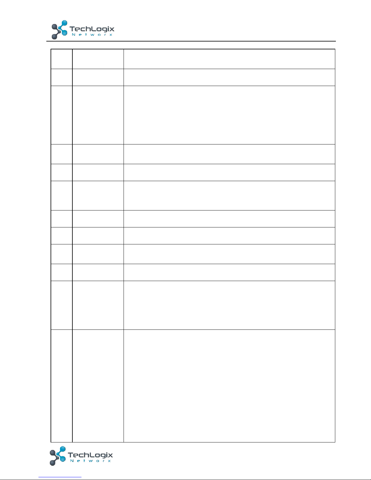
ü GREEN: Traffic with HDCP
ü Blinking GREEN: Traffic without HDCP
⑤
Power
Turns red when power is connected
⑥
TCP/IP
Connect to a PC to control the following items by Web-based
GUI:
ü Input signal switching
ü Volume adjustment
ü Turn on or off the display
ü Put the system into standby or start it
⑦
HDBT IN
/PoC
Connect to the PoC IN/HDBT OUT port of Transmitter with a
CAT5e cable.
⑧
TO DISPLAY
HDMI port to the display
⑨
FROM
TOUCH
SCREEN
USB-A connector. Connect to an interactive display and send the
USB signal back to signal source connected to the transmitter.
⑩
IR OUT
IR output for the display.
⑪
RS232
RS232 control for the display.
⑫
REMOTE
MUTE
NO or NC connection to mute the audio when triggered by a
mass notification system.
⑬
LINE OUT
Line level audio output.
⑭
MIC LINE
SWITCH
ü When the switch is set to “MIC”, the microphone input is
used to connect a dynamic microphone.
ü When the switch is set to “LINE”, the microphone input is
used for connecting a line level audio source or wireless
microphone output.
⑮
MIC
ü Microphone wiring:
1) Unbalanced connection:
“╧” connects to ground, and “-” connects to signal.
2) Balanced connection:
“+” connects to positive, “-” connects to negative and “╧”
connects to ground.
ü Line level wiring:
1) Unbalanced connection:
“╧” connects to ground, and “-” connects to signal.
2) Balanced connection:
Page 11
6
TL-CAV-01-HDV User Manual
www.tlnetworx.com
“+” connects to positive, “-” connects to negative and “ ╧ ”
connects to ground.
⑯
2x20 watts
at 4Ω
Speaker output.
⑰
DC24V
Power input for the included DC 24V 2.71A power adapter.
Page 12
7
TL-CAV-01-HDV User Manual
www.tlnetworx.com
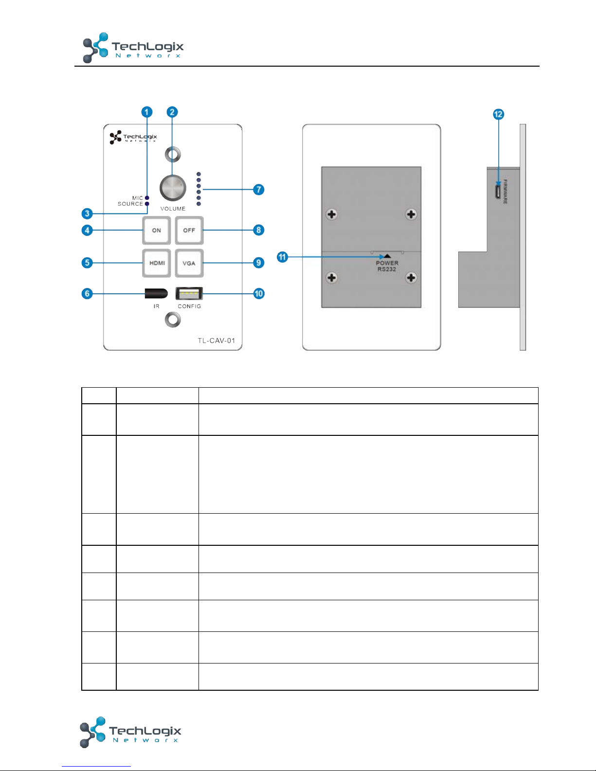
2.3 Control Panel
Figure 2-3 Control Panel
No.
Name
Description
①
MIC
MIC audio signal indicator, it will turn blue when the MIC audio
is selected to adjust its volume.
②
VOLUME
Knob
ü Press this button to mute or unmute speaker.
ü Long-press this button for 2 seconds to choose MIC or
SOURCE input audio need to be adjusted.
1. Clockwise adjustment to increase the volume.
2. Counter-clockwise adjustment to decrease the volume.
③
SOURCE
HDMI embedded audio signal indicator, it will turn blue when
the HDMI embedded audio is selected to adjust its volume.
④
ON
Turn on the display and system.
⑤
HDMI
Press it to select HDMI IN signal as input source.
⑥
IR
Built-in IR sensor to pass-through or capture IR commands for
the display.
⑦
Volume level
indicator
Six volume indicators to indicate volume level.
⑧
OFF
Turn off the display and system.
Page 13
8
TL-CAV-01-HDV User Manual
www.tlnetworx.com
⑨
VGA
Press it to select VGA IN signal as input source.
⑩
CONFIG
USB-A connector to import or export configuration data.
⑪
POWER
RS232
RJ45 connector. Connect to the POWER/RS232 port on the
Transmitter via CAT5e/CAT6a cable to transmit RS232 control
signal. Control Panel can be powered by Transmitter via this
port.
⑫
FIRMWARE
Micro USB port, used for firmware update.
Note: Pictures shown in this manual are for reference only.
Page 14
9
TL-CAV-01-HDV User Manual
www.tlnetworx.com
3. System Connection
3.1 Usage Precautions
1) Speakers must be connected before powering the receiver on.
2) All devices should be connected before powering the receiver on.
3) Use shielded solid core straight-thru Cat5e or greater with TIA/EIA T568B
terminations to connect the HDBT ports.
4) All devices should be connected before power on.
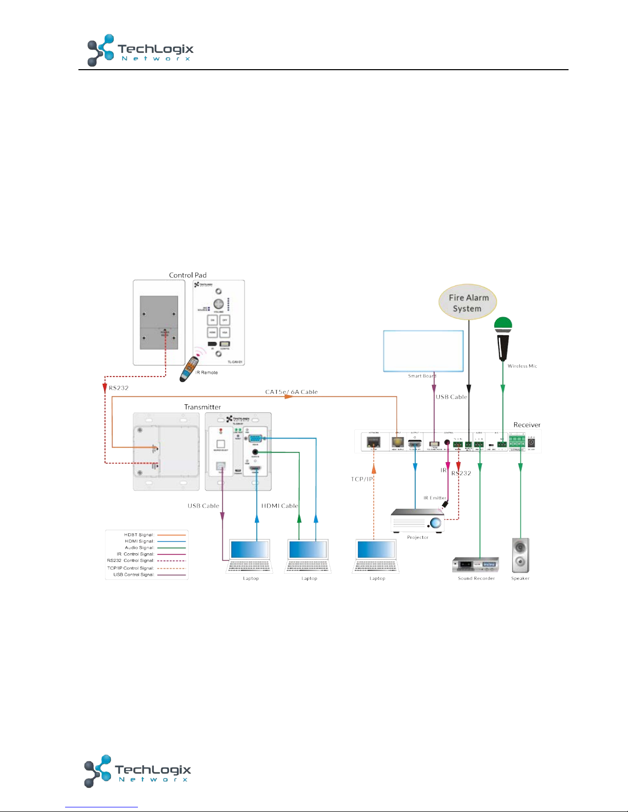
3.2 System Diagram
Figure 3-1 System Diagram
3.3 Connection Procedure
Step1. Connect an HDMI source device to HDMI IN port of Transmitter with a high-
quality HDMI cable.
Step2. Connect a VGA source device to VGA IN port of Transmitter with a high-quality
VGA cable.
Step3. Connect PC to TO PC port of Transmitter with USB control cable if connecting
Page 15

10
TL-CAV-01-HDV User Manual
www.tlnetworx.com
to an interactive display.
Step4. Connect HDBT OUT/PoC IN port of Transmitter and HDBT IN/PoC port of
Receiver on the rear panel with single shielded solid core straight-thru Cat5e or
greater cable with TIA/EIA T568B terminations.
Step5. Connect POWER RS232 port of Transmitter and POWER RS232 port of Control
Panel on the rear panel with single CAT5e or greater cable. The distance
between Transmitter and Control Panel should be kept within 5 meters.
Step6. Connect a display to the TO DISPLAY and RS232 port of Receiver.
Step7. Connect an interactive display to the FROM TOUCH SCREEN port of Receiver
with the included USB control cable.
Step8. Connect audio broadcast device to the LINE OUT port of Receiver.
Step9. Connect a microphone to the MIC port of Receiver
Step10. Connect REMOTE MUTE port of Receiver to the Fire Alarm System.
Step11. Connect a speaker to the 2x20Watt@4 port of Receiver.
Step12. Connect a PC to the TCP/IP port of Receiver for Web-based GUI control.
Step13. Connect the IR Emitter to the IR OUT port of Receiver, and then put it over the
IR receiver port of the display.
Step14. Connect DC24V 2.71A power adaptor to the power port of Receiver.
&
1) System Diagrams shown in this manual are for reference only.
2) Connect HDBT ports via single shielded solid core straight-thru Cat5e or greater
cable with TIA/EIA T568B terminations at both ends.
3.4 PoC Solution
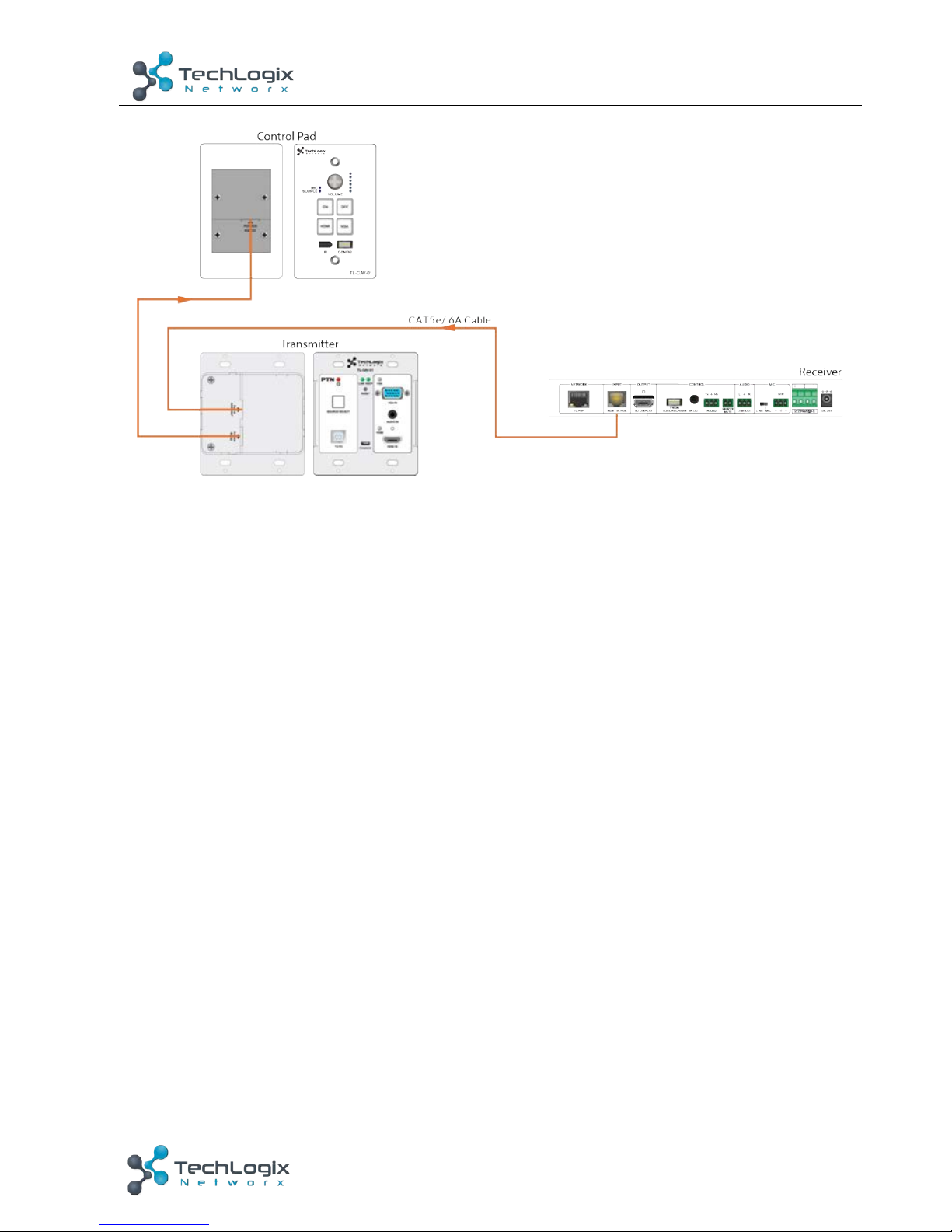
TL-CAV-01-HDV supports PoC, which allows all components in the kit to share the
same power supply and eliminates the need for extra power supplies at the remote
nodes.
Connect the DC24V 2.71A power adapter to the power port of Receiver,
Transmitter and Control Panel can be powered via the PoC solution, see the picture
below:
Page 16
11
TL-CAV-01-HDV User Manual
www.tlnetworx.com
Figure 3-2 PoC Solution Diagram
3.5 Typical Application
TL-CAV-01-HDV is ideal for any space that requires a couple video sources and needs
audio reinforcement. It is designed to solve some commonly inefficient issues, such as
difficulty when trying to switch signal sources and providing whole room audio. This
section provides a brief introduction to the typical application scenarios.
l Scenario 1: System Preparation
1. Press the “ON” button of Control Panel to turn on the display or long-press it to start
system.
2. Connect signal source (e.g. PCs) to the HDMI IN and VGA IN ports of Transmitter.
3. Turn on wireless microphone.
l Scenario 2: System use
1. Press the button “HDMI” or “VGA” to switch back and forth conveniently between
two HDMI signal inputs.
2. Long-press the knob “VOLUME” to choose the audio source, MIC audio or HDMI
embedded audio, that needs to be adjusted. Then, turn the knob clockwise to increase
the volume or counter-clockwise to decrease the volume.
3. Users in the rear of the room will clearly hear the meeting leader or teacher without
that person needing to yell to reach those users.
l Scenario 3: System shutdown
Press the button “OFF” to turn off display or long-press it to put the system into
standby.
Page 17

12
TL-CAV-01-HDV User Manual
www.tlnetworx.com
4. System Operation
4.1 IR Learning Function
IR learning function allows user to use the buttons of Control Panel to control the
display. The Control Panel has four buttons: “ON”, “OFF”, “HDMI”, and “VGA”. “HDMI”
and “VGA” do not support the IR learning function, because they are designed for
switching the HDMI signal sources.
l Setup Procedure:
1. Long-press the button “HDMI” until the buttons “ON” and “OFF” light up,
and then release “HDMI”. The blue backlight of “HDMI” will go out to enter
IR learning mode.
2. Press the button “ON” to enter IR learning status, and it will keep blinking
blue.
3. Press the corresponding button (such as the “On” button) on IR remote,
meanwhile, put IR remote close to the IR sensor of Control Panel.
4. Once user set up successfully, the button “ON” will stop blinking
5. Next, repeat the above steps to set another button “OFF”.
6. Finally, Long-press the button “VGA” to exit programming mode.
l Operating Procedure:
1. Press the button “ON” to turn on the display.
2. Press the button “OFF” to turn off the display.
&
² When the system enters IR learning status, long-press the “VGA” button for
more than 5 seconds to exit.
² If there is no interaction for 60 seconds, the system will exit automatically.
² The blue backlight of all buttons will go out once the system exits successfully.
4.2 Front Panel Button Control
l Via Control Panel
² There are two modes for controlling display and system: synchronous and
asynchronous control mode. They can be selected via the web-based GUI. For
more details, please refer to the 4.6.2 Setting Menu.
u Synchronous control:
Press the buttons “ON” or “OFF” on Control Panel to turn on/off the display
Page 18
13
TL-CAV-01-HDV User Manual
www.tlnetworx.com
and system concurrently.
u Asynchronous control:
Press “ON” to turn on display or long-press it to start system.
Press “OFF” to turn off display or long-press it to put system into standby.
² Press “HDMI” or “VGA” to switch to the appropriate input source.
l Via Transmitter
² Press “SOURCE SELECT” to select one source; press again to select next
source.
² Press “RESET” to reboot Transmitter.
4.3 USB Signal Return
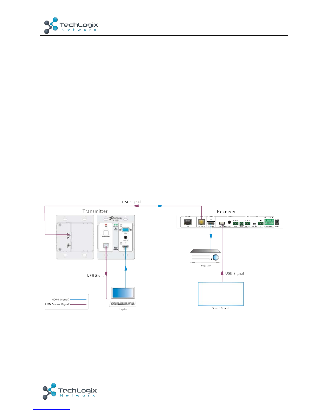
Receiver has a USB port (FROM TOUCH SCREEN) to connect with an interactive
display. When the user makes annotations or control gestures on the interactive display,
the Receiver will transmit the USB signal to the Transmitter which is connected to a PC
via USB. Please refer to the return path of USB signal as shown as below.
Figure 4-1 Return Path Diagram
Note: The distance between Receiver and interactive display should be within 4m.
Otherwise, a special USB control cable should be used.
Page 19
14
TL-CAV-01-HDV User Manual
www.tlnetworx.com
4.4 RS232 control
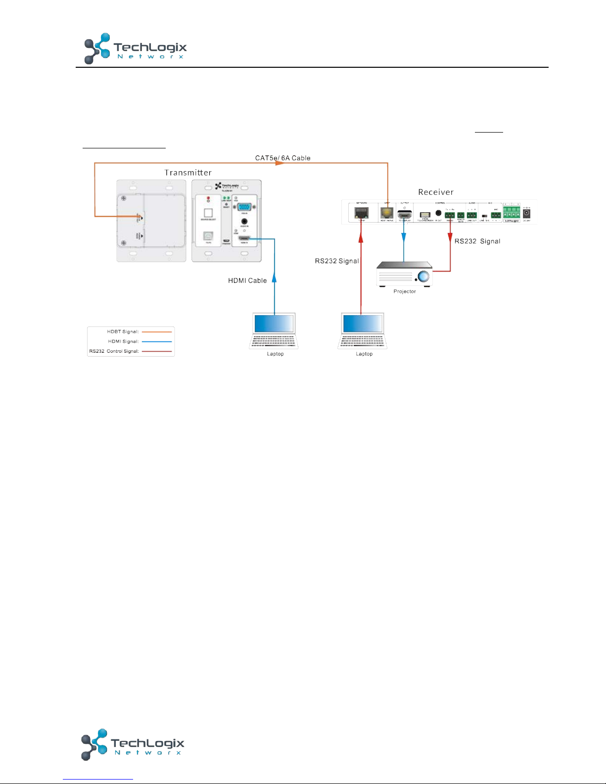
Receiver provides an additional RS232 interface to connect with a display, and then
control it by sending RS232 commands via Web-based GUI. Please refer to 4.6.3
Command Menu.
Figure 4-2 RS232 Control Diagram
4.5 IR control
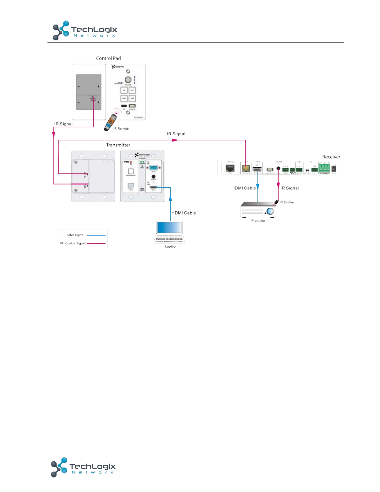
Control Panel provides a built-in IR sensor and Receiver provides an IR OUT port for IR
Emitter to control the display.
In this system, put IR Emitter over the IR sensor of the display. Point the IR remote of
display close to built-in IR sensor of Control Panel. The display can be controlled by IR
remote via the IR pass-through function.
Page 20
15
TL-CAV-01-HDV User Manual
www.tlnetworx.com
Figure 4-3 IR Control Diagram
Page 21
16
TL-CAV-01-HDV User Manual
www.tlnetworx.com
4.6 Web-based GUI Control
Except button control, USB control, RS232 control, IR control, TL-CAV-01-HDV can be
controlled via web-based GUI control. It allows users to interact with TL-CAV-01-HDV
through graphical icons and visual indicators.
Connect the TCP/IP port of the Receiver to Ethernet port of PC with twisted pair, and
then modify the PC’s network segment as the same as the TL-CAV-01-HDV’s. For
example, the IP address of PC can be modified as 192.168.0.177.
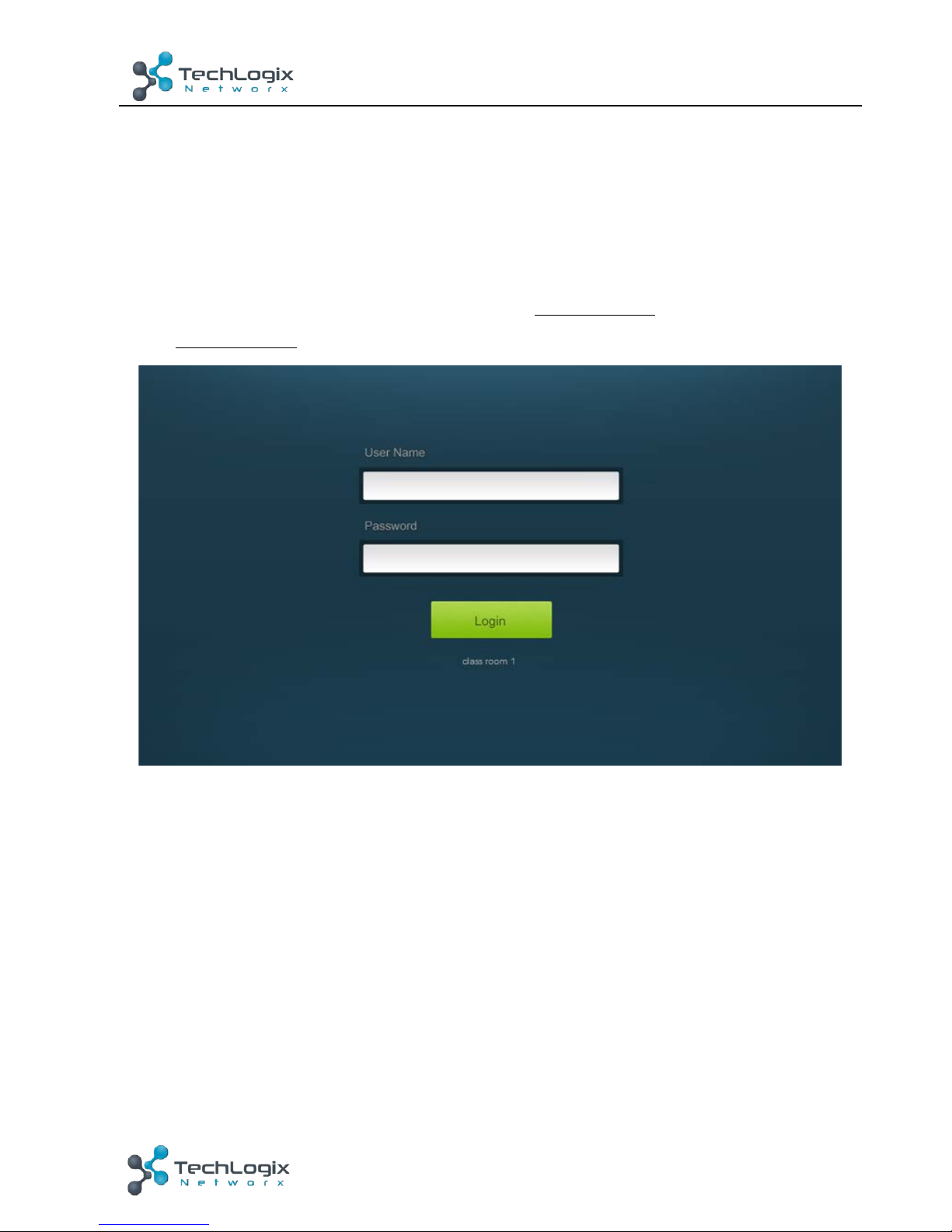
Type 192.168.0.178 in your browser, it will enter the log-in interface shown as below:
Figure 4-4 Login GUI
There are 2 selectable usernames – admin (default password: admin) and user (default
password: user).
&
Logging in as admin can access more interfaces than user. Here is a brief introduction to
these interfaces in administrator mode.
4.6.1 Control Menu
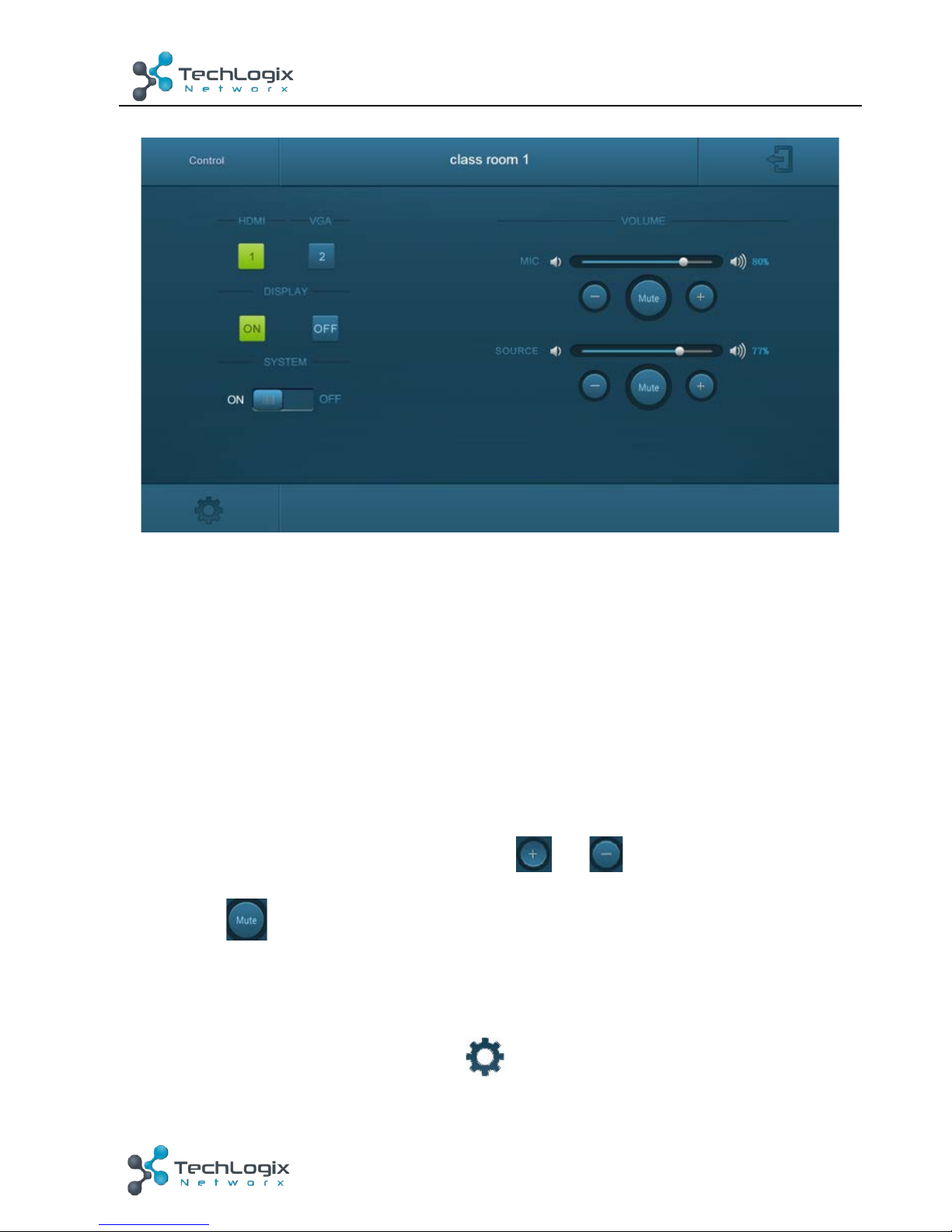
In log-in interface, type the username: admin, password: admin, and then click Login, it
will show the control menu as shown below:
Page 22
17
TL-CAV-01-HDV User Manual
www.tlnetworx.com
Figure 4-5 Control Menu
In this interface, you can:
² Click “HDMI” or “VGA” in the HDMI & VGA bar to choose a signal source
² Click “ON” or “OFF” in the DISPLAY bar to turn on or turn off the display device,
here is a display.
² Select “ON” or “OFF” in the SYSTEM bar to turn on or turn off system.
² Adjust the volume of Microphone and signal source by moving slider or clicking
the buttons below the slider. Click “Mute” to mute Mic or source sounds; click this
button again to unmute.
Note
:
When using an iPad to click the button or , it is normal behavior that
the button will flash.
4.6.2 Setting Menu
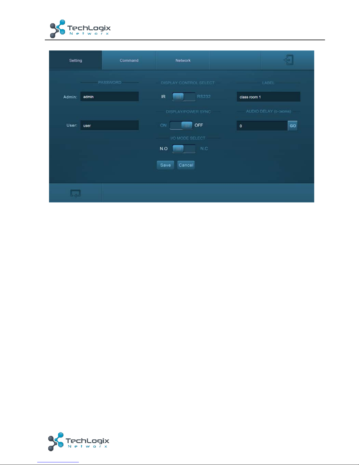
In control menu, click the setting button in the lower left corner to access the
Setting menu as shown in the screenshot below:
Page 23
18
TL-CAV-01-HDV User Manual
www.tlnetworx.com
Figure 4-6 Setting Menu
In this interface, you can:
² Modify the passwords on the left PASSWORD bar.
² Select the control mode for turning on/off display in DISPLAY CONTROL SELECT
bar, default mode is IR control.
² Select “ON” or “OFF” in the DISPLAY/POWER SYNC bar to turn on/off the
synchronous control mode for display and system. This option is only active if the
display is controlled via RS232.
u When synchronous control mode is ON, press the buttons “ON” or “OFF” on
Control Panel to turn on/off the display and system concurrently
u When synchronous control mode is OFF, press “ON” on Control Panel to turn
on display or long-press it to start system, press “OFF” to turn off display or
long-press it to put this system into standby.
² Select “N.O” or “N.C” in the I/O MODE SELECT bar to turn on/off the REMOTE
MUTE port connected Fire Alarm System. Under “N.O” mode, when the fire alarm
system creates a signal short, the audio output of HDMI signal source will be set
to mute.
² Modify the label shown on Log-in interface.
² Set the AUDIO DELAY, and the range is 0~340ms to ensure audio and video signal
reach the users simultaneously.
Page 24
19
TL-CAV-01-HDV User Manual
www.tlnetworx.com
² Click “Save” to save these settings.
4.6.3 Command Menu
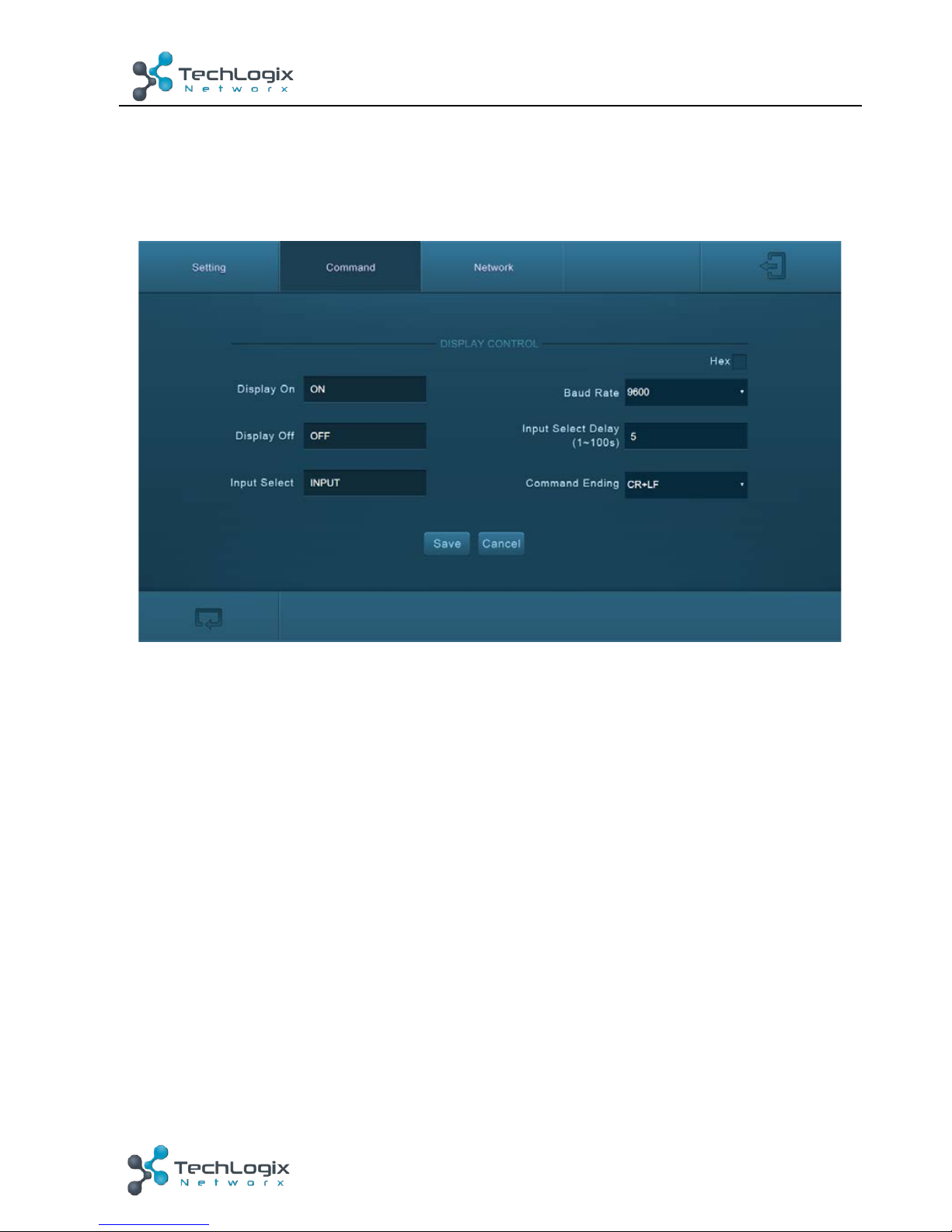
In setting menu, click “Command” to access command menu as shown in the below:
Figure 4-7 Command Menu
In this interface, you can:
² Enter the commands of display in Display On/Display OFF/Input Select box to
turn on/turn off display or select signal source.
² Select the Hex checkbox to set the format of commands as hexadecimal. The
default is character format.
² Modify the baud rate, the default value is 9600 and the selectable range is
2400~115200.
² Set the Input Select Delay. The default time is 5 seconds. Send the command
typed in Display ON box, wait 5 seconds, and then send the command typed in
Input Select box.
² Different displays may require a specific command ending, such as a carriage
return (CR) or line feed (LF). Please check the device manufacture's manual and
select the appropriate command to broadcast at the end of the RS232 string.
² Click “Save” to save these settings.
Note: For more details about commands, please refer to the display’s user manual.
Page 25
20
TL-CAV-01-HDV User Manual
www.tlnetworx.com
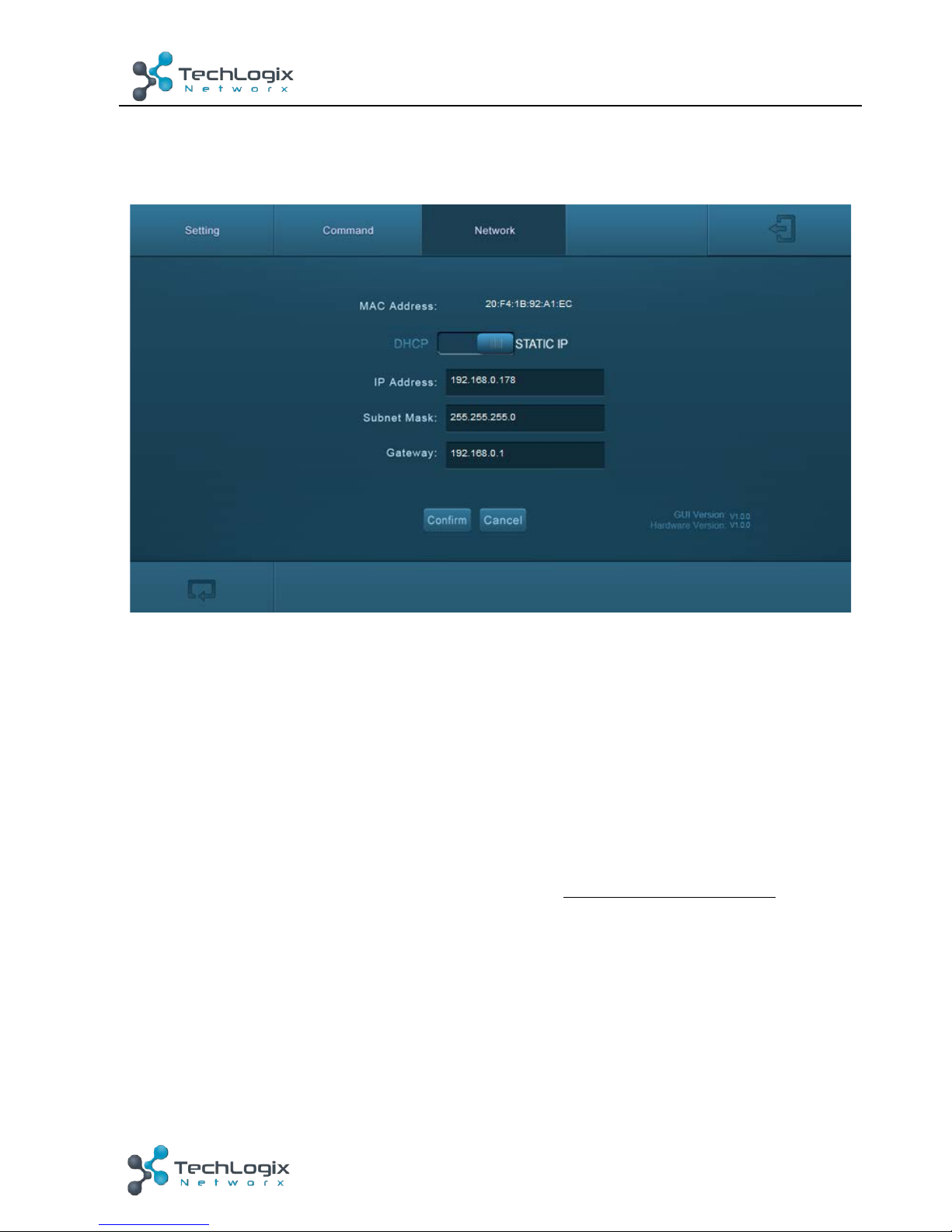
4.6.4 Network Menu
Click “Network” to access command menu as shown in the below:
Figure 4-8 Network Menu
In this interface, you can:
Select dynamic or static IP mode. Under static IP mode, IP address, subnet mask, and
gateway can be set. Make sure the IP addresses are different to avoid IP conflict.
While in DHCP mode, if you need to get the IP address, it can be checked via UPNP
function.
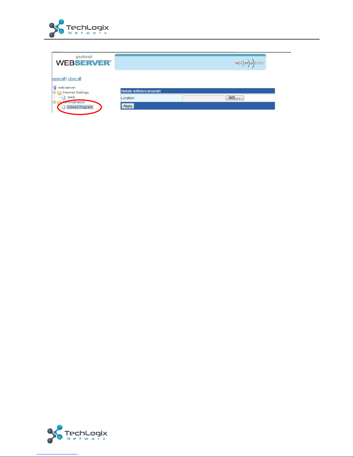
4.6.5 GUI update
GUI for TL-CAV-01-HDV supports online updates at http://192.168.0.178:100.
Type the username and password (the same as the GUI log-in settings, modified
password will be available only after rebooting) to log in the configuration interface.
After that, click Administration at the source menu to get to Upload Program as shown
below:
Page 26
21
TL-CAV-01-HDV User Manual
www.tlnetworx.com
Select the desired update file and press Apply, it will start upgrading then.
4.7 Copy and load configuration data
The system IR or RS232 configuration can be copied to a USB thumb drive and loaded
into additional systems or be saved as a backup.
4.7.1 Copy Configuration Data
1) Insert a 4GB or smaller FAT32 formatted thumb drive into the CONFIG port
on Control Panel.
2) Press “HDMI 2” + “OFF” simultaneously for three seconds on Control Panel.
As soon as the buttons are released, they will light up while the copy is
progress.
3) Remove the thumb drive from the CONFIG port once the buttons go dark.
4.7.2 Load configuration data
1) Insert a 4GB or smaller FAT32 formatted thumb drive with saved
configuration data into the CONFIG port on Control Panel.
2) Press “HDMI 1” + “ON” simultaneously for three seconds on Control Panel,
the blue backlight of buttons will go out while import successfully.
3) Remove the thumb drive from the CONFIG port once the buttons go dark.
4) Enter the Command Menu via Web GUI, the loaded RS232 commands will be
shown, and then press “Save’’ to confirm them.
Page 27
22
TL-CAV-01-HDV User Manual
www.tlnetworx.com
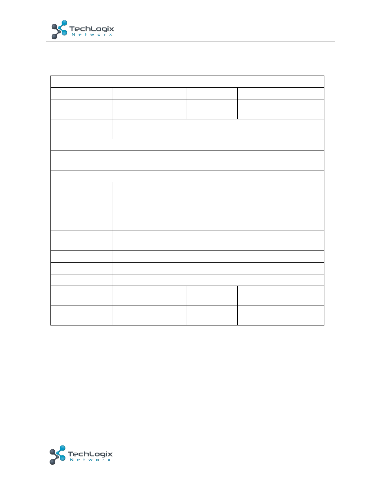
5. Specification
5.1 Transmitter
Video Ports
Input Ports
1 x HDMI, 1 x VGA
Output Port
1 x HDBT+Power
Input
Connectors
19-pin Type A
HDMI female
Output
Connector
RJ45
Transmission
Mode
HDBaseT
Control Ports
1 x USB
1 x Micro USB
General
Resolution
1920x1080 (24/25/30/50/60Hz), 1920x1080 (50/60Hz),
1920x1080i (50/60Hz), 1600x900, 1366x768, 1280x720,
1920x1200, 1680x10501440x900, 1360x768, 1280x800,
1600x1200, 1400x1050, 1280x1204, 1024x768, 800x600,
640x480
Deep Color
24-Bit at 1920x1080(24/25/30/50/60Hz)4:4:4;
48-Bit at 1920x1080(50/60Hz)4:4:4
Signal Extension
Up to 30 meters @ 1080p/60 via Cat5e/6a cable.
Bandwidth
10.2Gbps
HDMI Standard
Support HDMI1.4 and HDCP1.4
Temperature
0 ~ 50° C
Reference
Humidity
10% ~ 90%
Dimension
(W*H*D)
105 x 89 x 44 mm
Weight
242g
Page 28
23
TL-CAV-01-HDV User Manual
www.tlnetworx.com
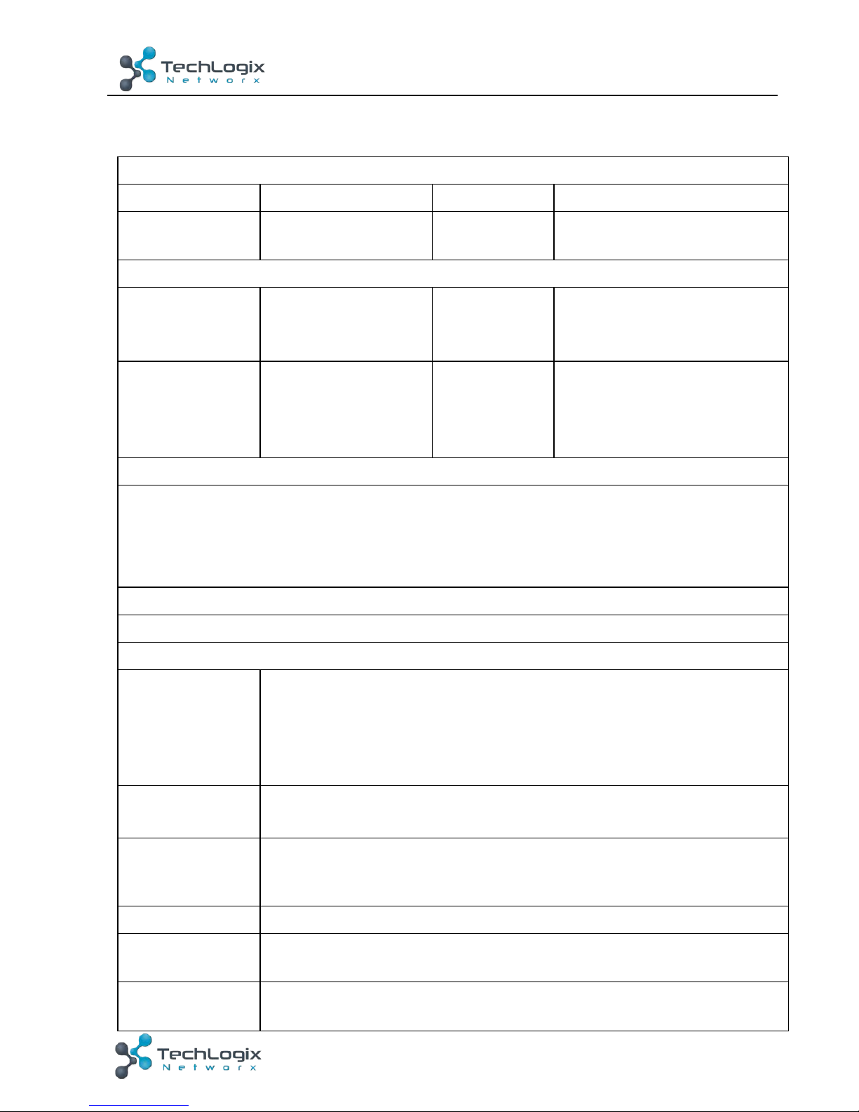
5.2 Receiver
Video Ports
Input
1 x HDBT+Power
Output
1 x HDMI
Input Connector
RJ45
Output
Connector
19-pin Type A HDMI female
Audio Ports
Input
1 x MIC
Output
1 x amplifier
(2x20Watt@4Ω),
1 x analog audio(LINE OUT)
Input Connector
3-pin pluggable
terminal block
Output
Connector
4-pin pluggable terminal
block;
3-pin pluggable terminal
block
Control Ports
1 x USB-A
1 x IR OUT (3.5mm jack)
1 x RS232 (3-pin pluggable terminal block)
1 x TCP/IP (RJ45)
Other Ports
1 x REMOTE MUTE(2-pin pluggable terminal block)
General
Resolution
1920x1080 (24/25/30/50/60Hz),1920x1080 (50/60Hz),
1920x1080i (50/60Hz), 1600x900, 1366x768, 1280x720,
1920x1200, 1680x1050, 1440x900, 1360x768, 1280x800,
1600x1200, 1400x1050, 1280x1204, 1024x768, 800x600,
640x480
Deep Color
24-Bit at 1920x1080 (24/25/30/50/60Hz) 4:4:4;
48-Bit at 1920x1080 (50/60Hz) 4:4:4
Audio Format
HDMI embedded audio: PCM/Dolby/DTS
MIC input audio: PCM/Dolby Digital/DTS/DTS-HD
Analog output Audio: PCM
Signal Extension
Up to 30 meters @ 1080p/60 via Cat5e/6a cable.
Bandwidth
10.2Gbps
HDMI Standard
Support HDMI1.4 and HDCP1.4
Page 29
24
TL-CAV-01-HDV User Manual
www.tlnetworx.com
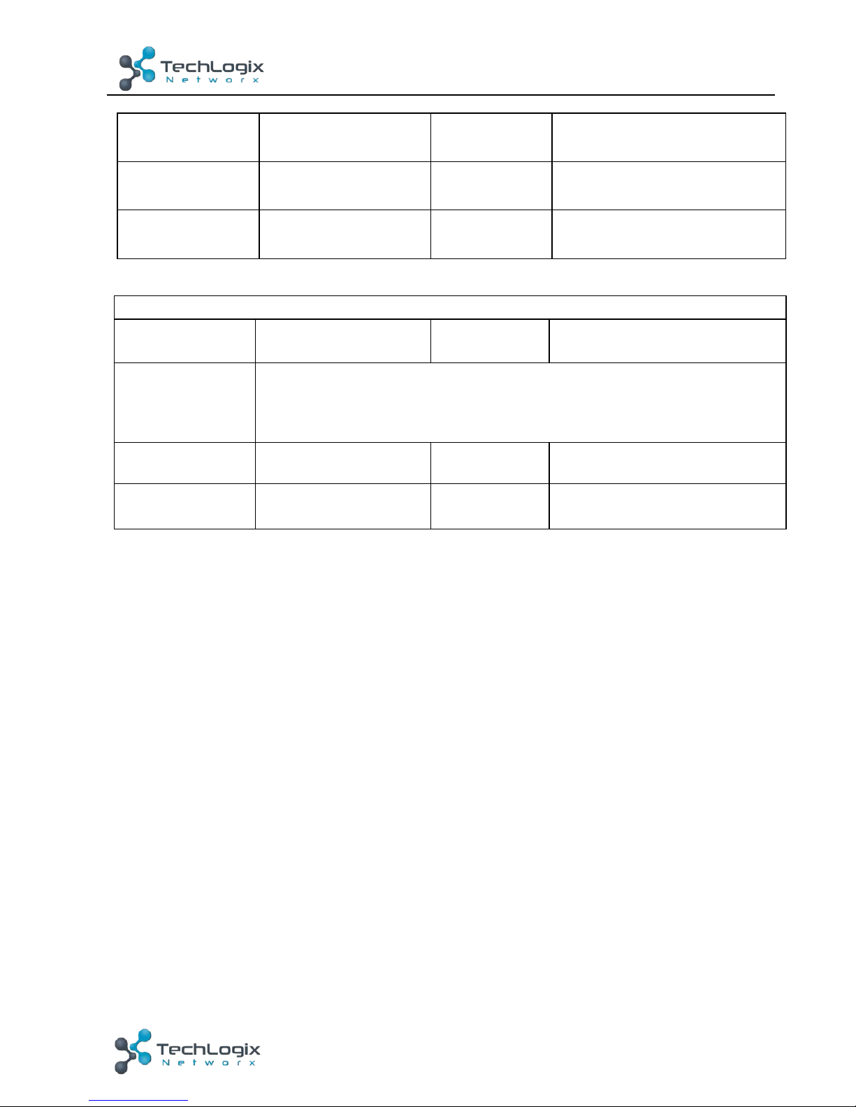
5.3 Control Panel
Specification
Program Port
1 x Micro USB
Output Port
1 RS232+Power
Others
1 x Knob
4 x buttons (ON, OFF, HDMI, VGA)
1 x IR in-built sensor
Temperature
0 ~ 50° C
Humidity
10% ~ 90%
Case
Dimensions
114x70 x34mm
Weight
140g
Power Supply
DC24V 2.71A
Power
consumption
55w (Max)
Temperature
0 ~ 50° C
Reference
Humidity
10% ~ 90%
Dimension
(W*H*D)
250x 31 x 130 mm
Weight
642g
Page 30
25
TL-CAV-01-HDV User Manual
www.tlnetworx.com
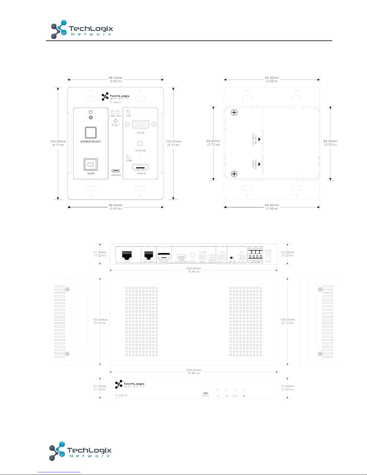
6. Panel Drawing
6.1 Transmitter
Figure 6-1 Dimension of Transmitter
6.2 Receiver
Figure 6-2 Dimension of Receiver
Page 31
26
TL-CAV-01-HDV User Manual
www.tlnetworx.com
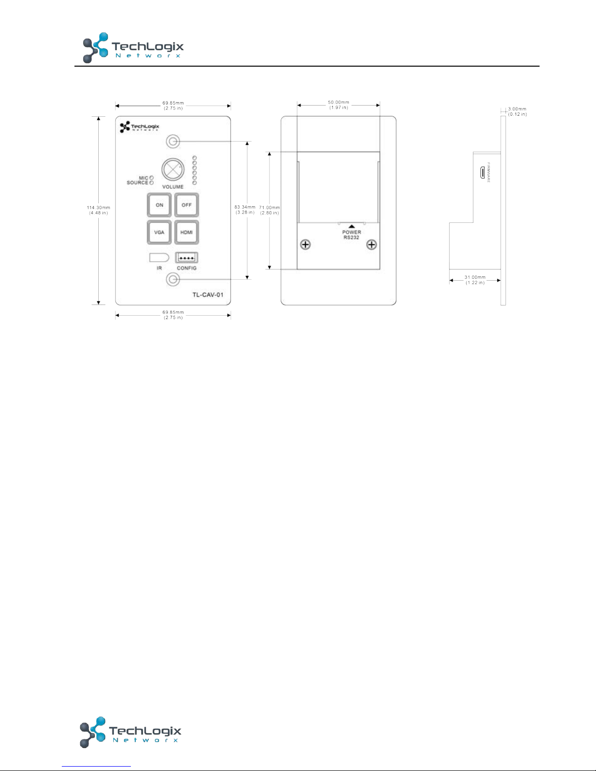
6.3 Control Panel
Figure 6-3 Dimension of Control Panel
Page 32
27
TL-CAV-01-HDV User Manual
www.tlnetworx.com
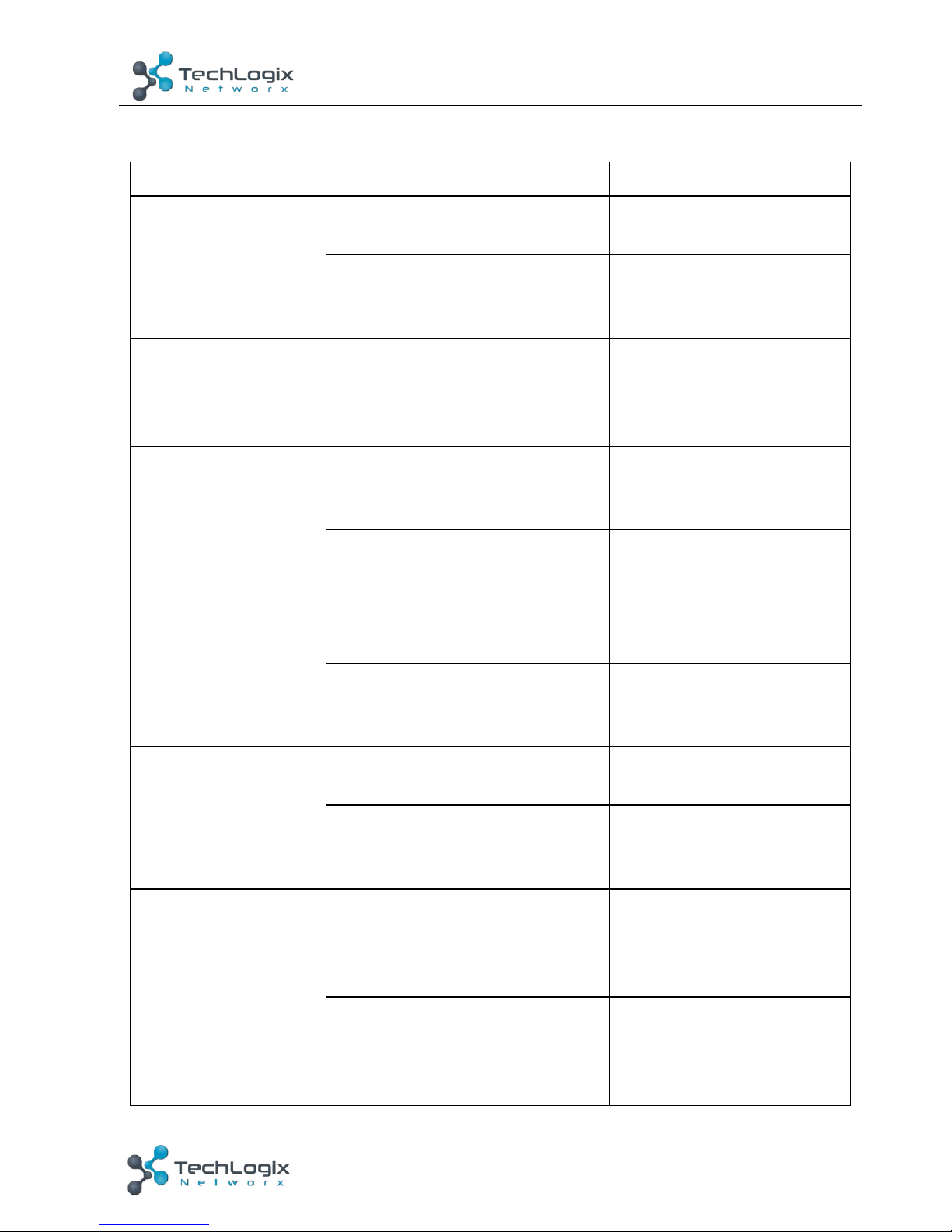
7. Troubleshooting & Maintenance
Problems
Causes
Solutions
No reaction to any
operation, power
indicator is off
Haven’t been powered on.
Insert power adapter to
the receiver.
The poor quality of network
cable.
Should the replacement
CAT5e/CAT6a cable of
high quality.
POWER indicator
doesn’t work or no
respond to any
operation
Loose or failed power cord
connection
Ensure the power cord
connection is good
Color lose or poor
picture quality
Signal loss caused by long
transmission distance beyond
effective value.
Make sure the connecting
cable is within 30m and of
good quality.
Bad quality of the HDMI or
VGA cable.
Ensure the cables used at
source, transmitter,
receiver and display are
properly connected and
are of good quality.
HDMI cables are too long to
transmit high-resolution HDMI
signal successfully.
Shorten the length of
HDMI cables.
No video output
Communication cables has no
connection or bad connection.
Recheck all cables and
ports.
The display that you use is
incompatible with this device.
It is recommended that
you use mainstream
display.
No audio output
Input source and output device
are connected to the wrong
ports.
Check again and make
sure input source and
output device are
connected correctly.
Audio output device don’t
support the audio format.
Change for other output
devices that support the
audio formats listed in
Specifications.
Page 33
28
TL-CAV-01-HDV User Manual
www.tlnetworx.com
Unable to login to
Web-based GUI
The PC’s network segment has
not been modified.
The PC’s network
segment need to be set as
the same as the TL-CAV01-HDV’s
Static becomes
stronger when
connecting the video
connectors
bad grounding
Check the grounding and
make sure it is connected
well.
Cannot control the
display by control
device (e.g. a PC)
through RS232 port
Wrong RS232 communication
parameters
Make sure the RS232
communication
parameters are correct.
Cannot use the
device
the device is broken
Send it to authorized
dealer for repairing.
Need to reset to
factory defaults
Press and hold the On and
Off buttons on the wall
controller until all LEDs
turn off momentarily then
turn back on.
If your problem persists after following the above troubleshooting steps, seek further
help from authorized dealer or our technical support.
Page 34
29
TL-CAV-01-HDV User Manual
www.tlnetworx.com
8. After-sales Service
If there appear some problems when running this product please check and deal with
the problems reference to this user manual. Any transport costs are borne by the users
during the warranty.
1) Product Limited Warranty: We warrant that our products will be free from defects
in materials and workmanship for three years. Please see warranty page posted on
www.tlnetworx.com for more info.
2) What the warranty does not cover:
l Warranty expiration.
l Factory applied serial number has been altered or removed from the product.
l Damage, deterioration or malfunction caused by:
l Normal wear and tear
l Use of supplies or parts not meeting our specifications
l No certificate or invoice as the proof of warranty.
l The product model shown on the warranty card does not match with the
model of the product for repairing or had been altered.
l Damage caused by force majeure.
l Servicing not authorized
l Any other causes which does not relate to a product defect
l Delivery, installation or labor charges for installation or setup of the product
3) Technical Support: Email to our after-sales department or make a call, please inform
us the following information about your cases.
l Product version and name.
l Detailed failure situations.
l The formation of the cases.
Remarks: For any questions or problems, please try to get help from your local
distributor.
 Loading...