

Page 1
User Manual
TL-TP100-HDC2
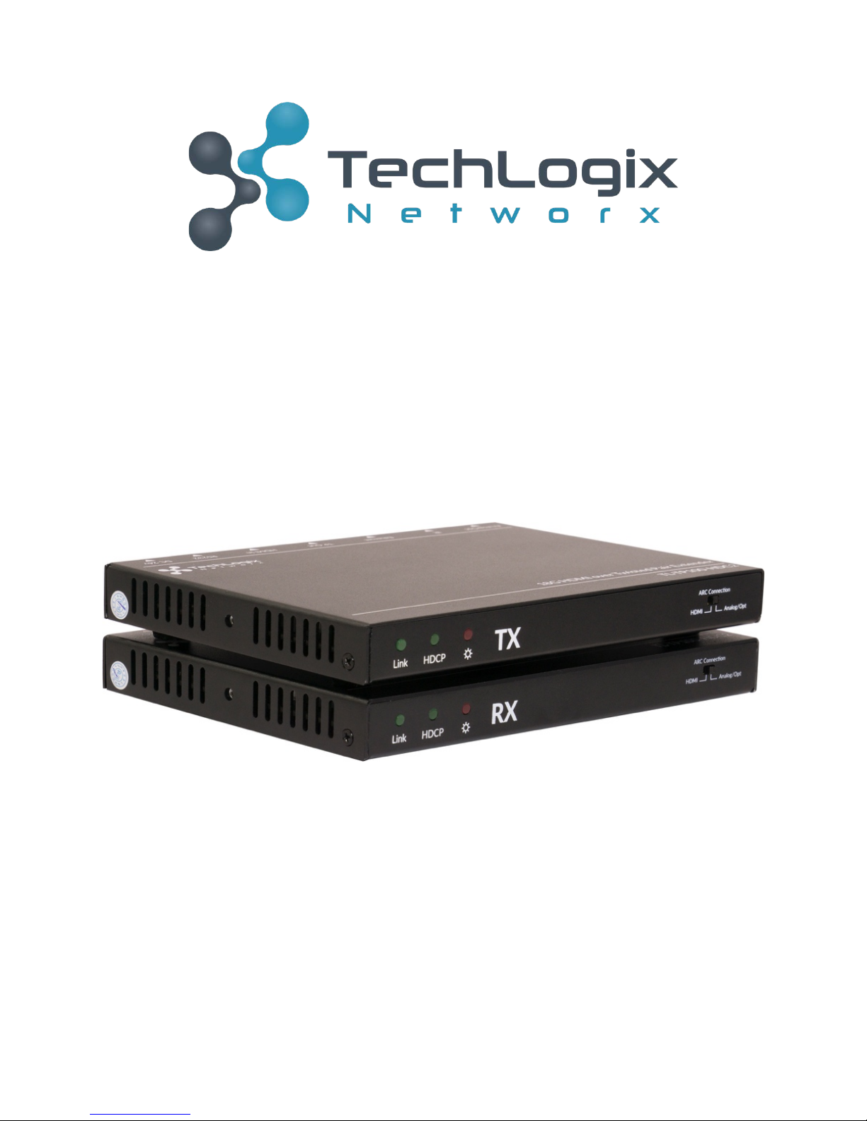
100m 4K/60 HDMI & Control Twisted Pair Extender Set
www.tlnetworx.com | +1-608-960-7242
All Rights Reserved
Version: TL-TP100-HDC2 _180125
Page 2

TL-TP100-HDC2 User Manual
Preface
Read this user manual carefully before using this product. Pictures shown in this manual are for reference only; the
actual product may vary.
This manual is only for operation instruction only and not for any maintenance or repair.
Trademarks
Product model and logo are trademarked. Any other trademarks mentioned in this manual are acknowledged as the
properties of the trademark owner. No part of this publication may be copied or reproduced without prior written
consent.
FCC Statement
This equipment generates, uses and can radiate radio frequency energy and, if not installed and used in accordance
with the instructions, may cause harmful interference to radio communications. It has been tested and found to
comply with the limits for a Class A digital device, pursuant to part 15 of the FCC Rules. These limits are designed to
provide reasonable protection against harmful interference in a commercial installation.
Operation of this equipment in a residential area is likely to cause interference, in which case the user at their own
expense will be required to take whatever measures may be necessary to correct the interference.
Any changes or modifications not expressly approved by the manufacture would void the user’s authority to operate
the equipment.
SAFETY PRECAUTIONS
To insure proper operation, please read all instructions carefully before using the device. Save this manual
for further reference.
l Unpack the equipment carefully and save the original box and packing material for possible future
shipment
l Follow basic safety precautions to reduce the risk of fire, electrical shock and injury to persons.
l Do not dismantle the housing or modify the module. It may result in electrical shock or burn.
l Using supplies or parts not meeting the products’ specifications may cause damage, deterioration or
malfunction.
l Refer all servicing to qualified service personnel.
l To prevent fire or shock hazard, do not expose the unit to rain, moisture or install this product near
water.
l Do not remove the housing of the device, as opening or removing housing may expose you to
dangerous voltage or other hazards.
l Install the device in a place with adequate ventilation to avoid damage caused by overheating.
l Keep the device away from liquids.
l Spillage into the housing may result in fire, electrical shock, or equipment damage. If an object or
liquid falls or spills on to the housing, unplug the device immediately.
l Do not use liquid or aerosol cleaners to clean this unit. Always unplug the power to the device before
cleaning.
l Unplug the power cord when left unused for a long period of time.
l If disposing of the unit, do not burn or mix with general household waste. The device must be
disposed of per local regulations for electronic recycling.
www.tlnetworx.com | +1-608-960-7242
Page 3

TL-TP100-HDC2 User Manual
Table of Contents
Introduction ........................................................................................................................................ 4
Features at a Glance ..................................................................................................................... 4
Package Contents.......................................................................................................................... 4
Panel Descriptions............................................................................................................................. 5
Transmitter ..................................................................................................................................... 5
Receiver ........................................................................................................................................... 7
System Connection ........................................................................................................................... 9
Usage Precautions ......................................................................................................................... 9
Connection Procedure ................................................................................................................. 9
Panel Drawings ................................................................................................................................ 10
Transmitter ................................................................................................................................... 10
Receiver ......................................................................................................................................... 11
Specifications ................................................................................................................................... 12
Troubleshooting and Maintenance .............................................................................................. 14
No image on display.................................................................................................................... 14
Color loss or poor picture quality:............................................................................................ 14
After-sales Service .......................................................................................................................... 15
www.tlnetworx.com | +1-608-960-7242
Page 4

TL-TP100-HDC2 User Manual
Introduction
The TechLogix TL-TP100-HDC2 revolutionizes high-bandwidth HDMI signal distribution
by leveraging HDBaseT technology to transmit 18G HDMI signals, including HDR and
4K@60 4:4:4, up to 100m (330 ft.) over standard twisted pair cabling.
The system works by lightly compressing signals above 10G for twisted pair transport,
and then uncompressing the signal at the destination end.
Flexible options for ARC (Audio Return Channel) allow the receiver to accept HDMI,
analog, or digital optical. The transmitter can output the audio on HDMI, analog, or
digital optical outputs.
Additional built-in features such as flexible power with Port-Saver™ protection, IR and
RS232 signal distribution, and Ethernet pass-through make the TL-TP100-HDC2
extremely powerful and extremely flexible.
Features at a Glance
• 18G HDMI (4K@60) up to 100m
• ARC on HDMI, Analog, and Optical Inputs and Outputs
• Deep color, DTS-HD, Dolby TrueHD compatible
• HDR compatible
• Light compression (2:1 ratio) on signals over 10G
• Single twisted pair transmission
• HDMI 2.0 / HDCP 2.2
• Built-in RS232, IR & Ethernet transmission
• Ethernet ports on send & receive
• Diagnostic LEDs
• Power from either transmitter or receiver
• Includes IR accessories & mounting ears
• Compatible with TechLogix rack-mounting systems
Package Contents
• [1] Transmitter
• [1] Receiver
• [2] Mounting kits
• [1] Power Supply
• [1] IR Emitter
• [1] IR Receiver
• [1] RS232 cable
• [2] Mini-Toslink Adapters
• [2] 3-Pin Terminal Blocks
www.tlnetworx.com | +1-608-960-7242
Page 5
TL-TP100-HDC2 User Manual
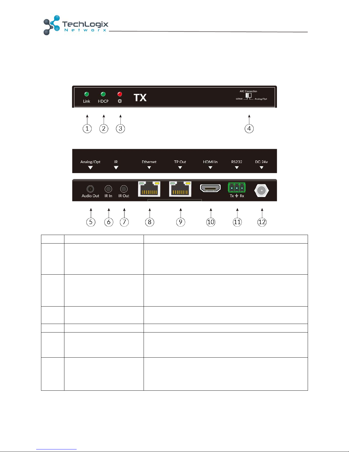
Name
Description
1
Link LED
HDBT link status indicator
• OFF: no link
• GREEN: link successful
• Blinking GREEN: link abnormal
2
HDCP LED
HDCP compliant indicator
• OFF: no HDMI traffic (no picture)
• GREEN: traffic with HDCP
• Blinking GREEN: traffic without HDCP
3
Power LED
OFF: No power
RED: DC power present
4
ARC Connection Switch
Select ARC output as HDMI or analog/optical
5
Audio Output
Dual function audio output port
• Standard 3.5mm TRS for analog stereo
• Optical 5.1 audio with included adapter
6
IR In
Connects to a 5V IR receiver (with carrier); signals
tranmitted to the remote receiver.
NOTE: Use TL-IR-CC if connecting to a third party
control system.
Panel Descriptions
Transmitter
www.tlnetworx.com | +1-608-960-7242
Page 6

TL-TP100-HDC2 User Manual
7
IR Out
Connects to a 5V IR emitter (with carrier); signals
tranmitted from the remote receiver
8
Ethernet
100m Ethernet interface. If a strong connection is
present, the yellow LED indicators on the
corresponding ports will blink and the green LED
indicators will remain solid.
9
Twisted Pair Output
Connect to the TP In socket on the receiver via a
twisted pair cable. Supports bi-directional PoC.
Port-Saver™ protection prevents damage to
Ethernet devices that may be connected during
device installation.
10
HDMI Input
Connect to an HDMI source
11
RS232
RS232 control connector
12
24V DC Input
Connect with DC24V 1.25A power adaptor. (Not
necessary if receiver connects with power).
www.tlnetworx.com | +1-608-960-7242
Page 7
TL-TP100-HDC2 User Manual
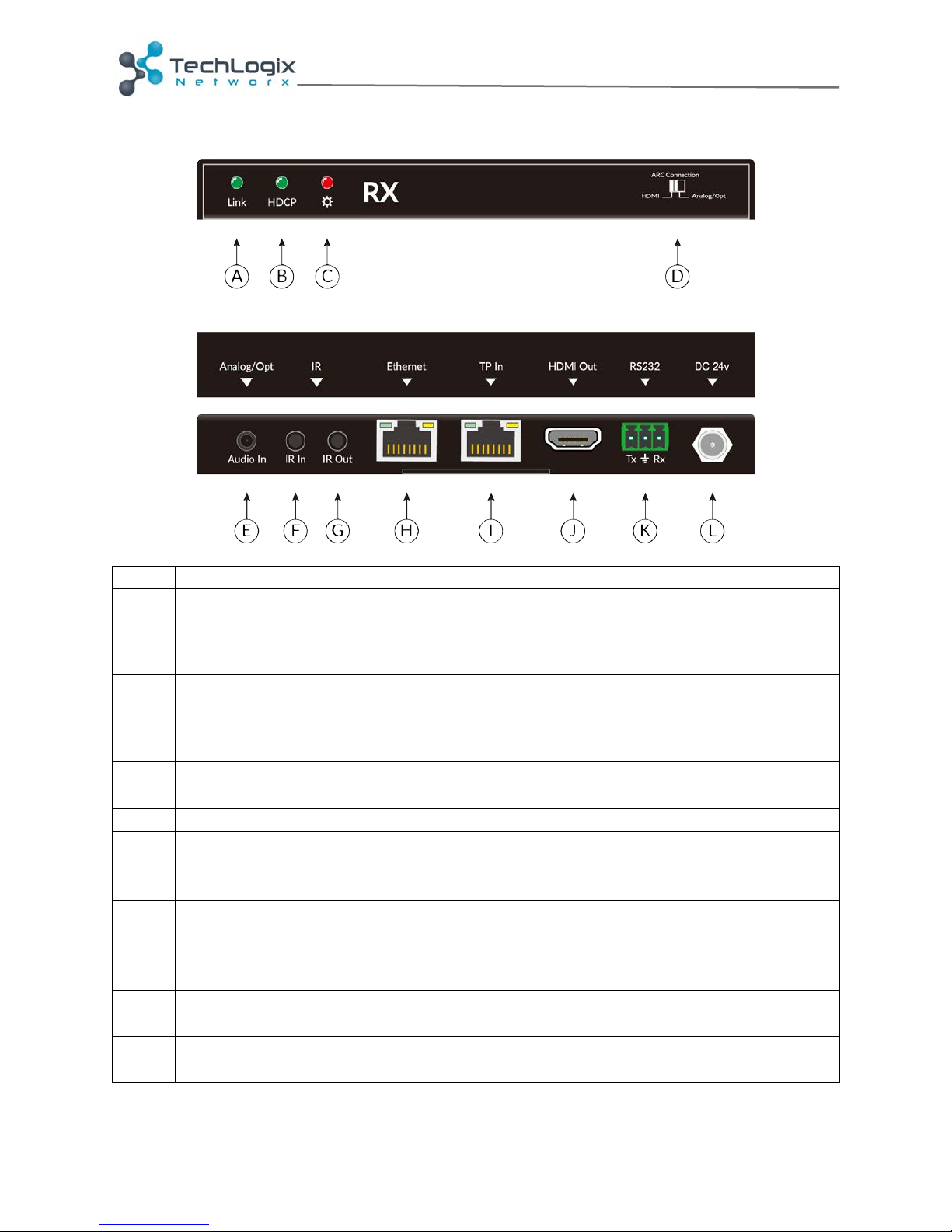
Name
Description
A
Link LED
HDBT link status indicator
• OFF: no link
• GREEN: link successful
• Blinking GREEN: link abnormal
B
HDCP LED
HDCP compliant indicator
• OFF: no HDMI traffic (no picture)
• GREEN: traffic with HDCP
• Blinking GREEN: traffic without HDCP
C
Power LED
OFF: No power
RED: DC power present
D
ARC Connection Switch
Select ARC input as HDMI or analog/optical
E
Audio Input
Dual function audio input port
• Standard 3.5mm TRS for analog stereo
• Optical 5.1 audio with included adapter
F
IR In
Connects to a 5V IR receiver (with carrier); signals
tranmitted to the remote receiver.
NOTE: Use TL-IR-CC if connecting to a third party
control system.
G
IR Out
Connects to a 5V IR emitter (with carrier); signals
tranmitted from the remote receiver
H
Ethernet
100m Ethernet interface. If a strong connection is
present, the yellow LED indicators on the
Receiver
www.tlnetworx.com | +1-608-960-7242
Page 8

TL-TP100-HDC2 User Manual
corresponding ports will blink and the green LED
indicators will remain solid.
I
Twisted Pair Input
Connect to the TP Out socket on the transmitter via
a twisted pair cable. Supports bi-directional PoC.
Port-Saver™ protection prevents damage to
Ethernet devices that may be connected during
device installation.
J
HDMI Output
Connect to an HDMI display
K
RS232
RS232 control connector
L
24V DC Input
Connect with DC24V 1.25A power adaptor. (Not
necessary if transmitter connects with power).
www.tlnetworx.com | +1-608-960-7242
Page 9

TL-TP100-HDC2 User Manual
System Connection
Usage Precautions
System should be installed in a clean environment that has a proper temperature and
humidity.
All of the power switches, plugs, sockets and power cords should be installed properly.
All devices should be connected before powering on the devices.
The twisted pair terminations for the devices should be a straight-thru conforming to the
TIA/EIA T568B standard.
Connection Procedure
1. Connect an HDMI source (such as a set top box) to the HDMI IN port of the
transmitter with an HDMI cable.
2. Connect TP OUT port of the transmitter to TP IN port of the receiver using a
twisted pair cable.
3. Connect an HDMI display to HDMI OUT port of the receiver with an HDMI cable.
4. If IR control is required, perform the following:
a. Connect the IR emitter to the IR OUT port on either the transmitter or
receiver.
b. Connect the IR receiver to the IR IN port on either the transmitter or
receiver.
5. If RS232 control is required, connect the RS232 port of the devices to be
controlled to the receiver or the transmitter.
6. If Ethernet (LAN) support is required, connect the devices to the Ethernet ports.
7. If ARC (audio return channel) from the display to the source is required:
a. Receiver side:
i. HDMI audio: Slide the ARC Connection switch to HDMI.
ii. Analog audio: Slide the ARC Connection switch to Analog/Opt.
Connect a standard TRS audio input on the Audio In port.
iii. Optical audio: Slide the ARC Connection switch to Analog/Opt.
Insert the included analog to optical adapter into the Audio In port.
Connect a standard optical to the adapter.
b. Transmitter side:
i. HDMI audio: Slide the ARC Connection switch to HDMI.
ii. Analog audio: Slide the ARC Connection switch to Analog/Opt.
Connect a standard TRS audio input on the Audio Out port.
iii. Optical audio: Slide the ARC Connection switch to Analog/Opt.
Insert the included analog to optical adapter into the Audio Out
port. Connect a standard optical to the adapter.
8. Connect the DC24V power adaptor to either the transmitter or receiver. Power
will be transmitter to the remote extender via the twisted pair cable.
www.tlnetworx.com | +1-608-960-7242
Page 10
TL-TP100-HDC2 User Manual
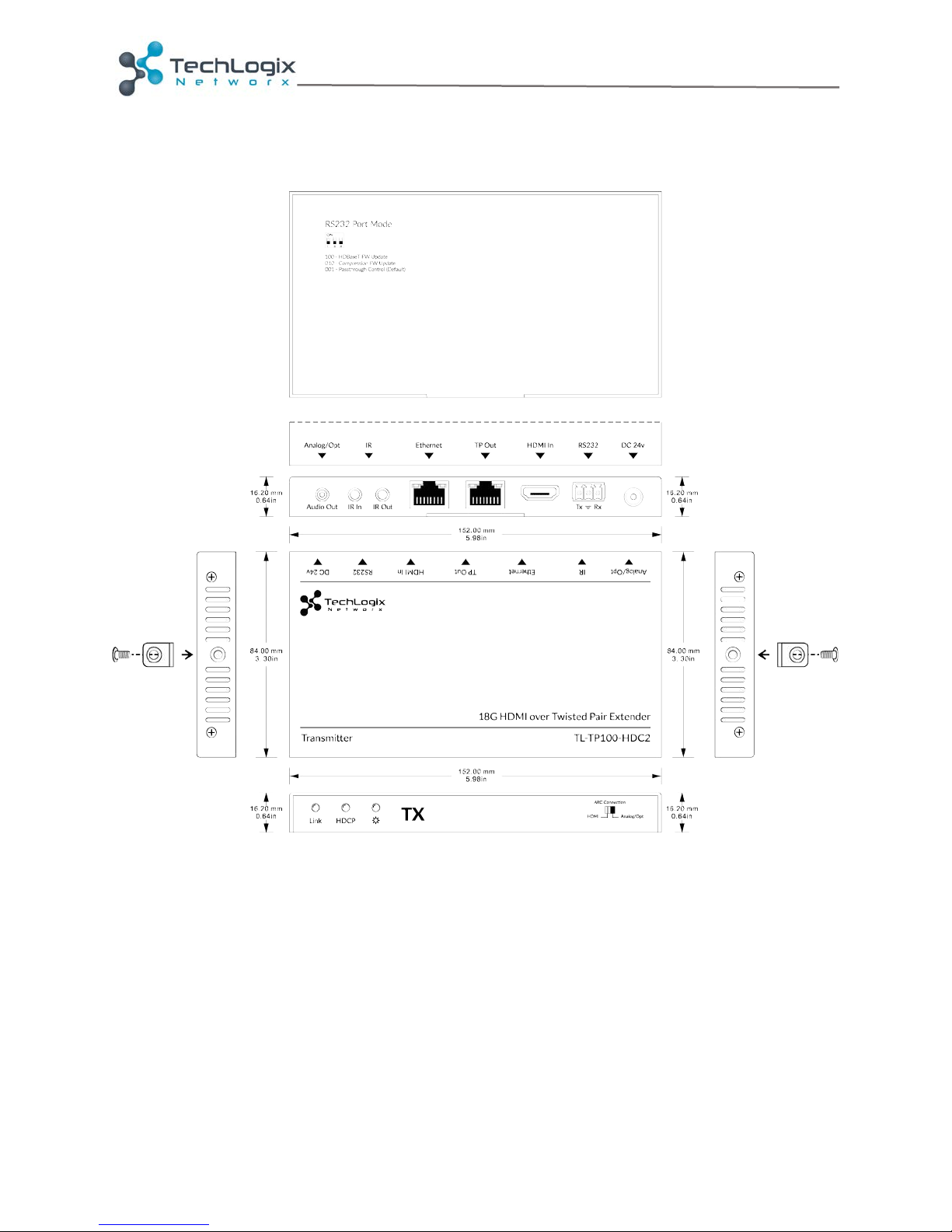
Panel Drawings
Transmitter
www.tlnetworx.com | +1-608-960-7242
Page 11
TL-TP100-HDC2 User Manual
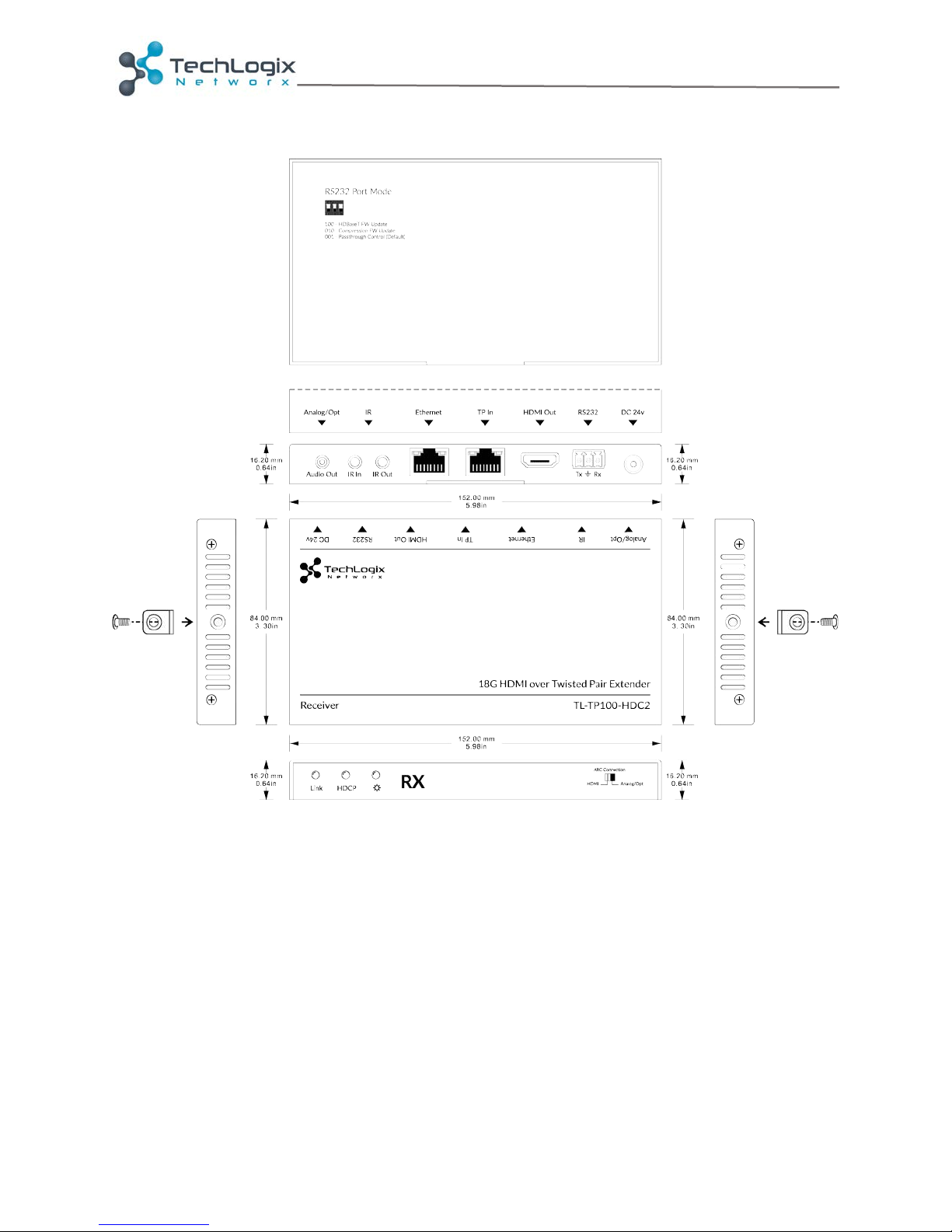
Receiver
www.tlnetworx.com | +1-608-960-7242
Page 12

TL-TP100-HDC2 User Manual
I/O Connections (Transmitter)
HDMI Input
HDMI Type A Receptacle (supports ARC)
Audio Output
3.5mm TRS / Mini-TOSLINK Combo (Stereo analog / Optical
Digital)
Twisted Pair
8P8C port (Shielded RJ45) with Port-Saver™ protection
IR Input
3.5mm TRS Jack
IR Output
3.5mm TS Jack
RS232
3pin phoenix socket (Tx/Gnd/Rx)
24V DC Power
5.5 mm Outside Diameter, 2.1 mm Inside Diameter Barrel
(Locking)
Ethernet
8P8C port (Shielded RJ45)
I/O Connections (Receiver)
HDMI Output
HDMI Type A Receptacle (supports ARC)
Audio Input
3.5mm TRS / Mini-TOSLINK Combo (Stereo analog / Optical
Digital)
Twisted Pair
8P8C port (Shielded RJ45) with Port-Saver™ protection
IR Input
3.5mm TRS Jack
IR Output
3.5mm TS Jack
RS232
3pin phoenix socket (Tx/Gnd/Rx)
24V DC Power
5.5 mm Outside Diameter, 2.1 mm Inside Diameter Barrel
(Locking)
Ethernet
8P8C port (Shielded RJ45)
Supported Video and Audio
Maximum Distances
1080p/720p: 100m (330 ft.)
4K@30/10G: 100m (330 ft.)
4K@60/18G: 100m (330 ft.)
Maximum Video Compatibility
4K@60Hz 4:4:4
HDR supported
Video Compliance
HDMI 2.0, HDCP 2.2, and CEC (Consumer Electronics Control)
HDCP Compatibility
HDCP 2.2 Conversion – output version matches sink (display)
version
Embedded Audio (HDMI)
Up to PCM 8 channel, Dolby Digital TrueHD, and DTS-HD
Master Audio
Embedded Audio (Analog)
PCM 2 channel 48kHz
Embedded Audio (Digital Optical)
Up to PCM 2 channel, 7.1 Dolby Digital Plus, and 7.1 DTS-HD
Input DDC Signal
5.0 volts p-p (TTL)
Input Video Signal
0.5 to 1.0 volts p-p
Ethernet Transmission Speed
Adaptive 10M/100M (max) / full duplex or half duplex
IR Carrier Frequency Range
33-55kHz at 5 volts
HDBaseT Signal Characteristics
Maximum Distance
100m (330 ft.)
Cable Requirements
Solid core shielded Category 5e, Category 6 or greater with
TIA/EIA-568B crimp pattern
Bandwidth
10.2 Gbps
Specifications
www.tlnetworx.com | +1-608-960-7242
Page 13

TL-TP100-HDC2 User Manual
Compression Signal Characteristics
Compression ratio
Up to 2:1 (adaptive for signals above 10.2gbps)
Compression type
Color Space Conversion (VLC)
Chassis and Environmental
Enclosure
Painted aluminum
Dimensions
152mm x 109mm x 16mm
Shipping Weight
0.71Kg (1.55 lbs) (Tx+Rx)
Operating Temperature
(Environment)
-10° to +40° C
Operating Temperature (Chassis)
45° C
Operating Humidity (Environment)
10% ~ 90%
Storage Temperature (Environment)
-15° to +70° C
Storage Humidity (Environment)
0%~55%
Power, ESD, Regulatory
Maximum Power Consumption
20W (max)
Power Supply
24V DC
ESD Protection
15KV
Port-Saver Protection™
Twisted Pair connections employ 802.3af PoE controllers
which do not send power unless connected to a request port.
Network switch ports or Ethernet ports will not be damaged by
accidental cross-patching.
Regulatory
CE, FCC
Other
Standard Warranty
3 Year
Diagnostic Indicators
Power, Link, and HDCP LEDs
Network Indicators
Link Speed and Activity
Included Items
Installation Guide, power supply, US power cord, mounting “L”
brackets (4 ea), mounting screws (4 ea), IR Transmitter, IR
Receiver, 3.5mm Toslink Adapters (2 ea)
www.tlnetworx.com | +1-608-960-7242
Page 14

TL-TP100-HDC2 User Manual
Troubleshooting and Maintenance
No image on display
• Ensure that the display device has been set to the correct input.
• Ensure that the HDMI cables used for both the source/transmitter and the
receiver/display are properly connected and are working. Test the HDMI cables
directly from a source to display and ensure their operation.
• Ensure that the twisted pair cable has not been damaged and that it has been
terminated correctly with T568B on both ends. A temporary length of twisted
pair cable can be used for testing to ensure that the devices are all compatible and
working properly.
• Ensure proper grounding of the power supply.
• Known issues with HDMI 1.2 source devices:
o Older compatibility (HDMI 1.2) may result in HDBaseT transmission issues.
Please contact Technical Support for a solution to these issues.
Color loss or poor picture quality:
• Ensure that the HDMI cables used for both the source and transmitter and the
receiver and display are properly connected and are of good quality. Test the
HDMI cables directly from a source to display and ensure their picture quality.
• Ensure proper grounding of the power supply.
• If the static becomes stronger or picture quality becomes worse when connecting
the video connectors, this may be due to improper grounding.
• Check the grounding and make sure all the components are properly grounded to
a common ground. Improper grounding may cause damage to the receiver.
www.tlnetworx.com | +1-608-960-7242
Page 15

TL-TP100-HDC2 User Manual
After-sales Service
Product Limited Warranty: We warrant that our products will be free from defects in
materials and workmanship for three years.
Warranty coverage may be voided when:
The warranty period has expired
The factory applied serial number has been altered or removed from the product
There is damage, deterioration or malfunction caused by:
Atypical wear and tear
Use of supplies or parts not meeting the specifications
No certificate or invoice as the proof of warranty
Damage caused by force majeure
Non-authorized service
Technical Support: When contacting TechLogix support, please have the following
information available:
Product part number
Installation and sale date
Detailed failure information
www.tlnetworx.com | +1-608-960-7242
 Loading...