


MREM 82 MTM-MF
MREM 82 MTMVR-MF
MIFARE® & NFC reader modules for MTM panels
User’s guide
© 2018 – 2019, TECH FASS s.r.o., Věštínská 1611/19, 153 00 Prague, Czech Republic, www.techfass.cz, techfass@techfass.cz
(Date of release: 2019/06/03, valid for FW version 7.00)

strana 2
1 Content
1 Content ....................................................................................................................... 2
2 MREM 82 reader module description .......................................................................... 3
2.1 MREM 82 MTM-MF module ................................................................................. 3
2.2 MREM 82 MTMVR-MF module ............................................................................ 3
2.3 Product versions for MTM module ....................................................................... 3
3 Technical parameters ................................................................................................. 5
3.1 Technical features................................................................................................ 5
3.2 Identification by the cell phone with OS Android® 4.4+ ......................................... 6
3.3 Mechanical design ............................................................................................... 6
3.4 Cabling ................................................................................................................ 7
3.5 Cable wiring ......................................................................................................... 7
3.6 Wiring description ................................................................................................ 7
3.7 Standard connection ............................................................................................ 8
3.8 LED Indication ..................................................................................................... 8
3.9 Installation instructions ......................................................................................... 8
4 Wiring diagram ........................................................................................................... 8
4.1 Simple connection of MREM 82 MTM-MF and MTM X1 or IP without POE.......... 8
4.2 Simple connection of MREM 82 MTM-MF and MTM IP with POE ........................ 9
4.3 Wiring diagram of MREM 82 in MTM panel integrated in system APS mini Plus 11
5 Setting parameters of the reader module .................................................................. 12
5.1 Configurable parameters.................................................................................... 12
5.2 Reader module parameters setting .................................................................... 13
6 Reader module functioning ....................................................................................... 13
6.1 “Door Open” function description ....................................................................... 13
6.2 Current limit of OUT 1 and OUT 2 ...................................................................... 13
6.3 Function permanent door lock release according to a time schedule ................. 14
6.4 Alarm states ....................................................................................................... 14
6.5 Standard operating modes ................................................................................. 15
6.6 Programming mode ........................................................................................... 15
6.7 ID expiration function ......................................................................................... 19
6.8 ID with Alarm flag function ................................................................................. 19
6.9 Antipassback function ........................................................................................ 19
6.10 Disabling function .............................................................................................. 20
6.11 Online authorization ........................................................................................... 21
7 Simplified access rights evaluation ........................................................................... 21
8 Declaration of conformity .......................................................................................... 22
9 Electrical waste ......................................................................................................... 22
10 Legislation ................................................................................................................ 22
11 Useful links ............................................................................................................... 22
11.1 MIFARE, NFC reader modules (13,56 MHz) ...................................................... 22
11.2 EM Marin, TF, Jablotron reader modules (125 kHz) ........................................... 23

strana 3
Pic. 1: MREM 82 MTM-MF
Pic. 2: MREM 82 MTMVR-MF
2 MREM 82 reader module description
The MREM 82 MTM reader module (13,56 MHz reader with an
embedded single door controller) are designed for connection to
the RS 485 bus of the APS mini Plus access control system. The
module is equipped with a Wiegand interface for connecting
additional reader with Wiegand output (for double-sided door
control). The reader modules are designed for installation in
MTM entry panels of CAME audio and video systems, where
they occupy only one module space. The modules are
customized for power supply and control from CAME entry
systems. Next to classic RFID cards or tags based on
MIFARE®, MIFARE® DESFire® and NFC
1
)
tag technology, the
reader is compatible with mobile phones equipped with NFC
technology and minimum OS Android® 4.4 Kit Kat (or higher). TF
Mobile ID application needs to be installed. The mobile phone
can be used for identification instead of classic cards (card
emulation mode).
2.1 MREM 82 MTM-MF module
The module is designed for installation into entry panel MTM of
CAME audio and video systems and is supplied with brushed
silver aluminum surface (Pic. 1).
2.2 MREM 82 MTMVR-MF module
The module is designed for installation into entry panel MTMVR (vandal resistant) of
CAME audio and video systems and is supplied with a surface made of black zinc alloy
called “zamak” (Pic. 2).
2.3 Product versions for MTM module
13,56 MHz product version overview
Product version
Product designation
Panel
Surface
Catalogue
number
Module
features
System
NFC
MIFARE
®
MREM 82 MTM-MF
APS mini plus
MTM
Brushed aluminum
53482004
✓
✓
MREM 82 MTMVR-MF
APS mini plus
MTM VR
Black zamak
53482014
✓
✓
WRE 82 MTM-MF
X
MTM
Brushed aluminum
51482004
✓
✓
WRE 82 MTMVR-MF
X
MTM VR
Black zamak
51482014
✓
✓
NREM 82 MTM-MF
APS 400
MTM
Brushed aluminum
54482004
✓
✓
NREM 82 MTMVR-MF
APS 400
MTM VR
Black zamak
54482014
✓
✓
Table 1a: 13,56 MHz product version overview (‘‘REM 82‘‘)

strana 4
125 kHz product version overview
Product version
Product designation
Panel
Surface
Catalogue
number
Module
features
System
125 kHz
MREM 81 MTM-EM
APS mini plus
MTM
Brushed aluminum
53481001
✓
MREM 81 MTM-TF
APS mini plus
MTM
Brushed aluminum
53481000
✓
MREM 81 MTMVR-EM
APS mini plus
MTM VR
Black zamak
53481011
✓
MREM 81 MTMVR-TF
APS mini plus
MTM VR
Black zamak
Na požádání
✓
WRE 81 MTM-EM
X
MTM
Brushed aluminum
51481001
✓
WRE 81 MTMVR-EM
X
MTM VR
Black zamak
Na požádání
✓
NREM 81 MTM-EM
APS 400
MTM
Brushed aluminum
54481001
✓
NREM 81 MTM-TF
APS 400
MTM
Brushed aluminum
54481000
✓
NREM 81 MTMVR-EM
APS 400
MTM VR
Black zamak
54481011
✓
Table 1b: 125 kHz product version overview (‘‘REM 81‘‘)
Table 1b mentions just all the rest of the RFID module versions into panel MTM based on
125 kHz (EM Marin, Jablotron, …). Links to these products are listed at the end of this
document.
Notes:
1)
NFC – card emulation mode by cell phone or tag; MIFARE® – MIFARE® family UID
media reading.
MIFARE®, MIFARE® Classic® and MIFARE® DESFire® are trademarks of NXP B.V.
Android® is a trademark of Google LLC.
BPT is family member of CAME.

strana 5
3 Technical parameters
3.1 Technical features
Technical features
Supply voltage
8 ÷ 28 VDC
Input
current
Nominal
42 mA @ 12V, 23mA @ 24 V
Peak
124 mA @ 12V, 62mA @ 24 V
Typical power
0,5 W
Peak power
1,5 W
ID
technology
MIFARE®, NFC (13,56 MHz)
3 cm (card ISO MIFARE Classic®)
Real-time clock
Yes, with 24 hrs. back-up
Memory
Cards
2,000 ID, 2 programming cards
Events
3,400
Time schedules
64
Inputs
1st input
Logical potential-free contact
2nd input
Logical potential-free contact
Output
Door lock 3)
1x open collector 0V active, max. 1A, 24V
Alarm
1x open collector 0V active, max. 1A, 24V
Signalization
1x LED
1x PIEZO
Tamper protection
Optional connection to IN2
System communication interface
RS-485
Alternative data communication interface
Wiegand
Table 2: Technical features
3)
The DC type of door lock has to be used only.

strana 6
3.2 Identification by the cell phone with OS Android® 4.4+
It is possible to use a cell phone equipped with NFC technology, operating system Android
4.4 Kit Kat (or higher) and installed TF mobile ID application for identification instead of the
cards or chips. You can download the application on Google Play for free.
Pic. 3: Google Play and TF mobile ID
3.3 Mechanical design
Pic. 4: MREM 82 MTM-MF
Mechanical design
Weight
122 g
Operating temperature
-25 ÷ 70 °C
Humidity
5 ÷ 95%, non-condensing
IP code
IP 54
IK code
IK 07, IK 09 (VR version)
Cable length
2 x 0,4 m
Color
MREM 82 MTM
Silver, brushed aluminum
MREM 82 MTM-VR
Black, zinc alloy “zamak”
Dimensions (Height x Width x Depth)
137,5 x 136 x 64 (34) mm
Table 3: Mechanical design

strana 7
3.4 Cabling
The cable consists twelve wires AWG 26. The wires are not dedicated for heavy loads,
OUT1, OUT 2 and appropriate power supply and ground wires are designed to be
connected to standard electromechanical mortise lock, door openers or magnets where the
DC current does not exceed the load of 1A. For inputs it is recommended to use signal
ground (brown wire nr. 10).
3.5 Cable wiring
OUT2
OUT1
GND
GND
12V
1
2
3 4 5
Table 4: Power supply cable wiring
W1/B
W0/A
IN2
IN1
GND B A 6 7 8 9
10
11
12
Table 5: Data cable wiring
3.6 Wiring description
Wiring description
#
Color
Purpose
1
Pink
Output 2; open drain, 1A (Alarm output)
2
Violet
Output 1; open drain, 1A (Lock)
3
Blue
GND power supply
4
Blue
GND power supply
5
Red
+ 8 ÷ + 28 VDC
6
Brown-green
WIEGAND data 1 / alternatively RS-485
7
White-green
WIEGAND data 0 / alternatively RS-485
8
Grey
Input 2 (IN2), configurable function
9
Yellow
Input 1 (IN1), configurable function
10
Brown
GND (0V) signal ground
11
White
RS–485 B
12
Black
RS–485 A
Table 6: Wiring description

Page 8
3.7 Standard connection
Connection
Input 1
Door contact, active when door closed; REX button
Input 2
Request to exit button or handle contact, 0 V signal when button or
handle active; Tamper; Disabling function
Output 1 (OC)
Door lock control open collector
Table 7: Standard connection
The door monitoring contact (IN1) is operational after its first change of status since
switching on the module. Full door lock timing acc. to tab. 9 is used when the door status
contact is not installed and no Door Forced and Door Ajar alarms are triggered.
3.8 LED Indication
LED indicators
Red
Continuously lit
Online operating mode via RS 485
Flashing with 4 s period
Offline operating mode
Green
ID media reading
Red/Green switching
Address setting mode, RS 485 bus testing
Yellow
Continuously lit / flashing
Programming mode
Short flashing with 1s per.
Indicating door lock release
Table 8: LED indication
3.9 Installation instructions
Generally, the noise can influence the reading functionality of the reader, so it is
recommended to check the place of installation if there could be some source of noise.
The reader uses passive RFID technology on 13,56 MHz frequencies, which could be
sensitive to RF noise sources, either radiated noise or conducted noise to the cable. This
noise could be generated by other equipment, which can generate strong electromagnetic
field or by noisy power supply, which inject noise to the cable. If there are any doubts, it is
recommended to perform a practical test before final mounting.
4 Wiring diagram
4.1 Simple connection of MREM 82 MTM-MF and MTM X1 or IP without POE
One of the simplest wiring of MREM 82 MTM-MF and MTM panel together is to use
OUTPUT 1 of MREM 82 MTM-MF to short-circuit the exit button input of the MTM panel.
The power can be handled by VAS/101 for example for both MREM 82 MTM-MF and MTM
itself.

Page 9
Pic. 5: Wiring diagram of MREM 82 MTM-MF and MTM panel for simple applications like
family houses. The reader can be powered from VAS/101 as well, OUTPUT 1 controls the
lock by short-circuiting the exit button input of the MTM panel.
4.2 Simple connection of MREM 82 MTM-MF and MTM IP with POE
If there is a LAN switch with integrated POE, the MTM panel and MREM 82 MTM-MF can
be both powered from POE. The estimation of power requirement should be calculated for
example if there are more MTM modular modules used. In this case POE 802.3af does not
have to provide enough power and POE+ 802.3at should be used.

Page 10
Pic. 6: Utilization of POE power supply.

Page 11
4.3 Wiring diagram of MREM 82 in MTM panel integrated in system APS mini
Plus
In larger application the MREM 82 MTM-MF reader can be a part of APS mini Plus access
control system backed up with a battery. In this case, the power supply of access control
system is separated from the power supply of the intercom system to be able to control the
door when the main power grid is off and the intercom is off.
Pic. 7: Wiring of MREM 82 MTM-MF as a part of battery power backed up system APS mini
Plus.

Page 12
5 Setting parameters of the reader module
5.1 Configurable parameters
Configurable parameters
Parameter
Possible range
Default setting
Door lock release time
0 255 s
7 s
Door lock control setting
Direct / reverse
Direct
Door lock relay function setting
Standard / toggle / pulse
Standard
Permanent door lock release according to
a time schedule
Never / Schedule index
Never
Door lock status indication
YES / NO
NO
Acoustic signal of door lock release
YES / NO
YES
Door ajar time
0 255 s
20 s
First input configuration
Door contact / REX button
Door contact
Second input configuration
REX button / handle contact
/ external tamper / tamper /
disabling function
REX button
Acoustic signalization time - Forced door
0 255 s
30 s
Acoustic signalization time – Door ajar
0 255 s
0 s
Acoustic signalization time – APB alarm
0 255 s
0 s
Signalization time – Card alarm
0 255 s
30 s
Antipassback function setting
See chapter 6.10
Disabled
Automatic summer time adjustment
YES / NO
YES
Release lock with REX button when
tamper alarm active
YES / NO
YES
Online authorization timeout
0 25500 ms
800 ms
Standalone authorization after timeout
YES / NO
YES
Saving events in
the module’s
archive
Door opened
Enabled / Disabled
Enabled
Door closed
Enabled / Disabled
Enabled
Input 2 On
Enabled / Disabled
Enabled
Input 2 Off
Enabled / Disabled
Enabled
Strike released
Enabled / Disabled
Enabled
Strike closed
Enabled / Disabled
Enabled
Table 9: Configurable parameters

Page 13
5.2 Reader module parameters setting
Detailed instructions for setting reader module parameters are described in the APS
Reader configuration program user’s guide available at the address
http://www.techfass.cz/files/m_aps_miniplus_reader_en.pdf.
6 Reader module functioning
The reader module supports the following functions:
• Standard “Door Open” function.
• Door status monitoring.
• Exit-devices contact monitoring.
• Acoustic signalization (and online) activated when any alarm condition occurs.
The “Door Open” function can be activated in 3 different ways:
• Reading a valid ID (card, key fob…).
• Pressing the exit button (according to configuration) – cannot be used in alarm
condition.
• Via communication line (program request).
6.1 “Door Open” function description
In case the standard function of the door lock relay is set, the door lock is released and the
beeper activated (when not disabled) when the “Door Open“ function is activated. Both
outputs stay active until the door is opened or the preset door lock release time has
elapsed - see configuration table.
In case the toggle function of the door lock relay is set, the door lock relay status is
switched and the beeper is activated (when not disabled) when the “Door Open” function is
activated. The beeper stays active until the door is opened or the preset door lock release
time has elapsed - see configuration table. The door lock relay status remains unchanged
until another “Door Open” function is activated.
In case the pulse function of the door lock relay is set, the door lock relay status is switched
for the time defined by the Pulse width parameter (ms) after the Door Open function is
activated.
In case the standard function of the door lock relay is set, reading a valid card during
door lock release resets the door lock release time.
6.2 Current limit of OUT 1 and OUT 2
There is a current limit protection on both outputs, 1 A. In case of capacitive load, the
current limit can be activated and disable the output. If there is a short current peak, it is
possible to turn on so called ‘’blanking time’’. This function disables the current limit
protection for the period set in the software to handle this short current peak. After this
period the current protection get back on its limit 1 A.

Page 14
By default, the blanking time is set to 6µs for the door lock output, and bit used for the
alarm output.
6.3 Function permanent door lock release according to a time schedule
When the function is set, the door lock is permanently released when relevant time
schedule is valid. Reading a valid ID is standardly announced via the communication line
(in online operating mode). The forced door alarm cannot be raised when the door lock is
permanently released.
The permanent door lock release function and the toggle function of the door lock relay
are mutually exclusive.
6.4 Alarm states
The reader module can get in following alarm states:
1) Forced door alarm
2) Door ajar alarm
3) Antipassback alarm (Time APB alarm, Zone APB alarm)
4) ID with Alarm flag alarm
Alarm state reporting is performed as follows:
• Via communication line (statuses 1, 2, 3, 4)
• By acoustic signal (beeper) (statuses 1, 2, 3).
Alarm signaling via communication line requires online running PC with relevant software
suitable for online operation (APS Administrator).
Two ways of acoustic signaling is carried out:
• Steady signal (tamper).
• Intermittent signal (forced door and/or door ajar, APB alarm).
Acoustic alarm signaling is stopped after a valid ID is presented or pre-set time interval is
elapsed, see the configuration table.
If any of the relevant alarm states (with setting of the signaling timer > 0) occurs, the alarm
state is announced on the communication line.
After terminating all alarm conditions the alarm status announcement is deactivated.
The alarm signaling is triggered by any alarm condition.
6.4.1 Forced Door alarm
The “Forced Door” alarm state is activated when the door is opened without activating the
“Door Open” function. The only exception is opening the door with the second module input
IN2 active and configured as a handle contact.

Page 15
6.4.2 Door Ajar alarm
If the door stays open until the pre-defined Door ajar timeout expires – see Tab. 9, the
“Door Ajar“ alarm is activated.
6.4.3 Antipassback alarm
The Antipassback alarm is raised when an ID is read during the Time APB counter is
running or when the ID is blocked by a Zone APB.
6.4.4 ID with Alarm flag alarm
ID with Alarm flag alarm occurs when an ID with the Alarm flag is read.
6.4.5 Reading ID during alarm state
Reading an ID doesn’t affect the alarm state, reading a valid ID only terminates the
acoustic alarm announcement followed by “Door Open” function. Reading an invalid ID only
interrupts the acoustic announcement of the alarm state while signalizing “Invalid ID”.
6.5 Standard operating modes
The reader module can be in either online or offline operating mode. The module’s
functionality is identical in both operating modes; the events archive is read from the reader
module’s memory when the module goes online.
.
When a programming card is read (while
in either online or offline mode), the module goes into programming mode.
6.6 Programming mode
The module enters programming mode by reading one of the two programming cards
(cards “+” and “-“). The programming mode cannot be entered while the module is in
hardware address setting mode (for modules with HW address setting via the
communication line). The module’s functionality in programming mode can be seen in
pictures 5 a-d.
It is not possible to use time schedules when inserting cards in programming mode,
therefore cards are always valid.
Page 16
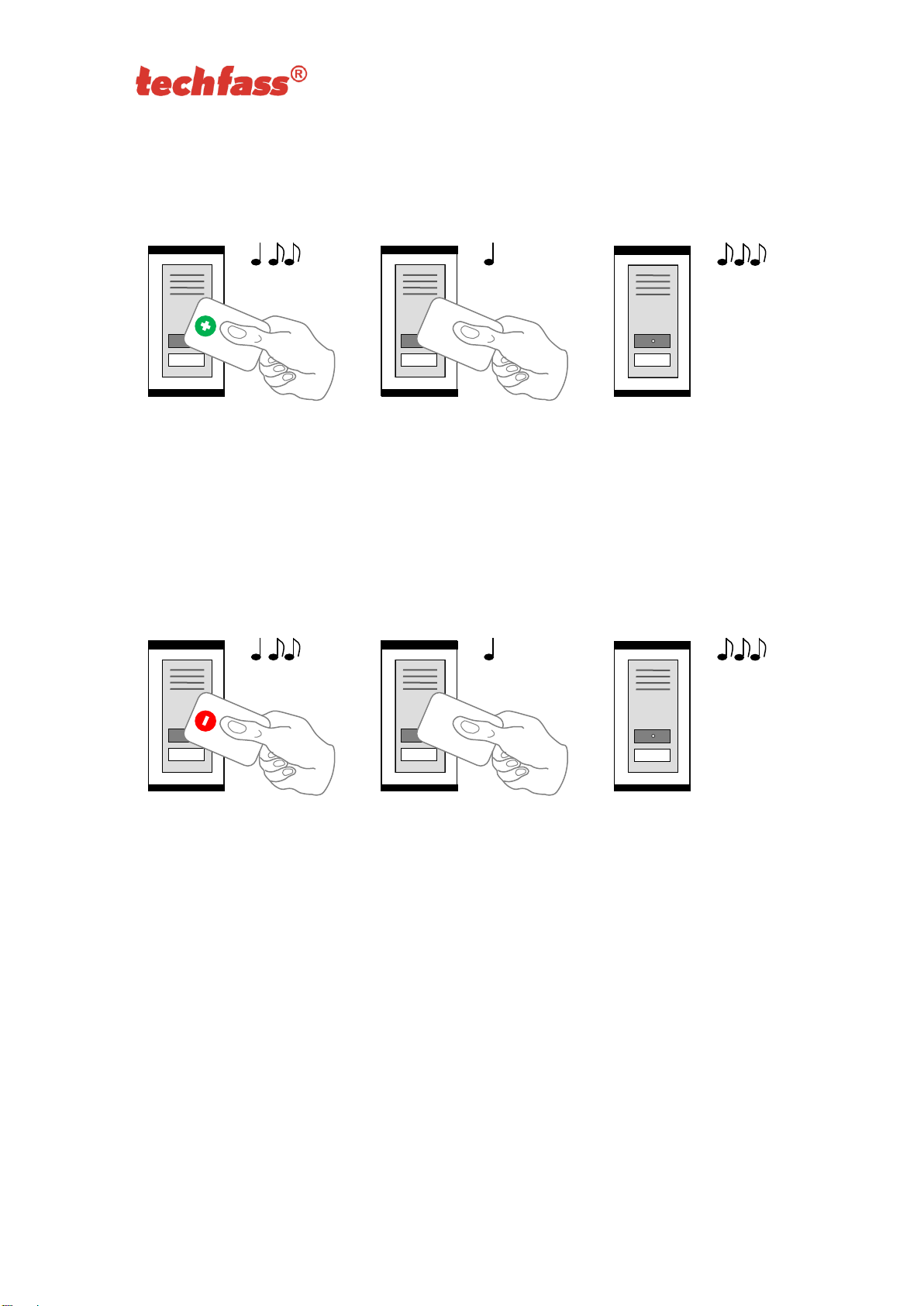
6.6.1 Inserting cards into the reader’s memory
Follow these steps for inserting cards into the reader module’s memory:
Step 1
Step 2
Step 3
Read the programming card
for inserting: the reader goes
into programming mode.
One by one, read the cards
which are to be granted
access.
About 15 seconds after
inserting the last card the
reader module goes back
into standard operating
mode.
Pic.5 a): Inserting cards
6.6.2 Deleting cards from the reader’s memory
For deleting the cards from the reader module’s memory use following steps:
Step 1
Step 2
Step 3
Read the programming card
for deleting: the reader goes
into programming mode.
One by one, read the cards
which are to have their
access revoked.
About 15 seconds after
deleting the last card the
reader module goes back
into standard operating
mode.
Pic.5 b): Deleting cards
Page 17
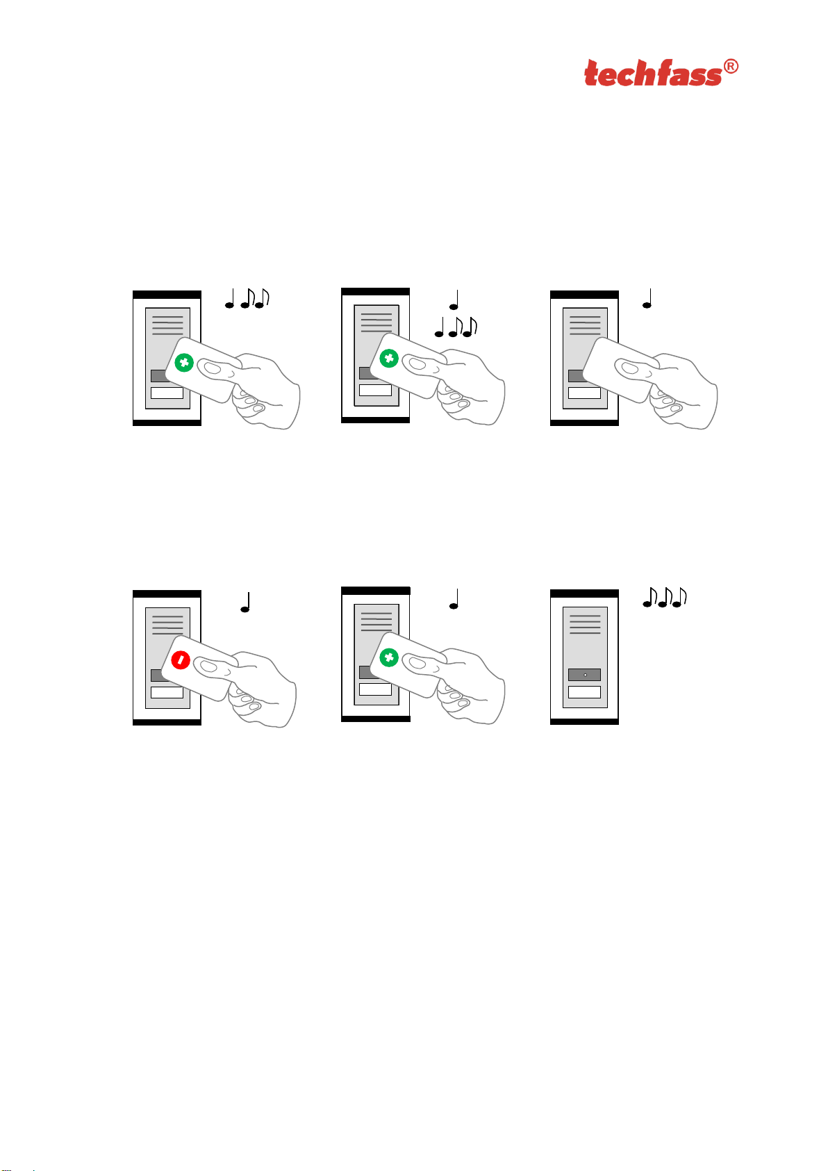
6.6.3 Deleting cards „above or below“
If a user loses his ID medium, it is usually impossible to delete the ID from the memory with
the procedure described in the previous chapter, since the medium is no longer available
(with an exception of entering the code at the keypad). Following procedure can be used
for deleting such ID. The procedure requires using an ID medium, which was inserted right
before or right after the ID medium, which should be deleted.
Step 1
Step 2
Step 3
Read the programming card
for inserting: the reader goes
into programming mode,
which is indicated by slow
flashing of yellow LED.
Read the programming card
for inserting 5 times in a row;
the reader will go into
Deleting cards “above or
below” mode indicated by
fast flashing of yellow LED.
Read a card, which is
located in the module’s
memory right before or right
after the card you wish to
delete. After this step the
module quickly flashes with
yellow LED.
Step 4 - A
Step 4 - B
Step 5
For deleting an ID located
right before the ID used in
precious step, read the
programming card for
deleting.
For deleting an ID located
right after the ID used in
precious step, read the
programming card for
inserting.
The reader module goes
back into standard operating
mode.
Pic.5 c): Deleting cards “above or below”

Page 18
6.6.4 Deleting all cards from the reader’s memory
Follow these steps for deleting all cards from the reader module’s memory:
Step 1
Step 2
Step 3
Read the programming card
for deleting: the reader goes
into programming mode.
Read the programming card
for deleting 5 times in a row;
the reader will erase all cards
from its memory.
The reader module goes
back into standard
operating mode.
Pic.5 d): Deleting all cards
6.6.5 Recommended method for access rights management (using prog. cards)
In case of managing access rights of plenty of users (using programming cards only), it is
appropriate to establish a table, which summarizes operation with the reader module
memory. All operations (adding and deleting cards) should be stored in the table. Following
example shows correct usage of the programming cards and proper filing of the actions:
• Inserting 5 new cards using the procedure from chapter 6.6.1 – Read + (inserting)
programming card, read cards 1-5, after 15 s the programming mode is exited,
create a table.
Pic.5 e):
Table after inserting 5 cards
• Card 3 gets lost – Delete it using the card 4, which is available, and using the
procedure from chapter 6.6.3 – Read + (inserting) programming card, then 5x +
(inserting) programming card again, then card 4, and finally – (deleting)
programming card. Register the change in your table.
Pic.5 f): Deleting card 3 using the card 4, table after deleting card 3
position
card
1
card 1
2
card 2
3
card 3 (lost)
4
card 4 (available)
5
card 5
position
card
1
card 1
2
card 2
3
card 3
4
card 4
5
card 5
position
card
1
card 1
2
card 2
3
card 3
4
card 4
5
card 5
5x

Page 19
• Card 4 gets lost – Delete it using the card 2, which is available, and using the
procedure from chapter 6.6.3 – Read + (inserting) programming card, then 5x +
(inserting) programming card again, then card 2, and finally + (inserting)
programming card again. Register the change in your table.
Pic.5 g): Deleting card 4 using the card 2, table after deleting card 4
• It is necessary to add another card (card 6). We proceed with the procedure from
chapter 6.6.1 again. 1 – Read + (inserting) programming card, read cards 1-5, after
15 s the programming mode is exited. Register the change in your table.
Pic. 6
h): Table after inserting card 6
A new card is always inserted at the position after the last inserted card. In case of deleting
all cards using the procedure described in chapter 6.6.4, it is necessary to create a new
filing table.
6.7 ID expiration function
This function is implemented since the FW version 5.0.
It is possible to set an Expiration date for every ID stored in the module. When the date
occurs, the ID becomes invalid (expired). The expiration evaluation is performed on every
date change in the module’s RTC and when the access rights are downloaded.
6.8 ID with Alarm flag function
This function is implemented since the FW version 5.0.
It is possible so set an Alarm – ID flag for every ID stored in the module. When the ID is
read, relevant alarm is raised for preset time.
6.9 Antipassback function
This function is implemented since the FW version 5.0.
The Antipassback function is defined in two ways:
position
card
1
card 1
2
card 2
3
card 3
4
card 4
5
card 5
6
card 6
position
card
1
card 1
2
card 2 (available)
3
card 3
4
card 4 (lost)
5
card 5
position
card
1
card 1
2
card 2
3
card 3
4
card 4
5
card 5

Page 20
• Time APB – user cannot repeatedly use his ID for defined time
• Zone APB – user cannot repeatedly enter an area, where he is already present
The Antipassback function is used only for the users, whose access is driven by a time
schedule. The users with access always granted are not affected by the Antipassback
function.
The Antipassback flags for an ID can be reset by inserting the ID again with use of the
programming cards (offline solution). All Antipassback flags are also reset whenever new
access rights data are downloaded from the program.
Both Zone and Time Antipassback flags are written either immediately after an ID is read,
or after relevant door is opened (relevant input is disconnected).
6.9.1 Time Antipassback
The Time Antipassback is defined by the ABP timer initial value (in minutes), which is set to
the ID after passing at the reader module. If the users uses the ID at the address during the
timer for the ID is running, the Time APB alarm is raised. Following parameters affect the
Time APB function:
• APB timer initial value – defines the Time APB flag (timer) value set to the ID after
passing at the reader module. If a user uses the ID again before the timer elapses,
Time APB alarm is raised.
• Open door after APB time alarm – if the option is enabled, the Door open function is
performed after the Time APB alarm is raised.
6.9.2 Zone Antipassback
The Zone Antipassback is defined by enabling the option for the relevant address. The
Zone APB flag is set for the ID when passing at the reader module. If a user uses the ID
again when the Zone APB flag is set, the Zone APB alarm is raised. Following parameters
affect the Zone APB function:
• Enabled – enable/disable general Zone APB flag setting.
• Enable in offline mode – if the option is not set, the module operates in offline mode
like if the APB function was not implemented.
• Open door after APB Zone alarm – if the option is enabled, the Door open function is
performed after the Zone APB alarm is raised.
6.10 Disabling function
This function is implemented since the FW version 5.08.
The module disabling function can be set at the second input. The logic of the function is
configurable. The module behavior is as described below when the disabling function is
active:
• User with access driven by a time schedule cannot run the door open function
• User with access always granted is not affected by the disabling function
• Remote door open function cannot be performed
• Remote identification with ID is disabled for users with access driven by a time
schedule

Page 21
The disabling status changes and disabled actions are logged in the events archive.
6.11 Online authorization
Since the FW version 5.11 the Online authorization of ID can be used in APS mini Plus
system. When the feature is used, the ID validity is resolved in connected PC. To be able
to use this authorization mode, the reader module has to be equipped with a MLO license.
7 Simplified access rights evaluation
The model of access rights contains time schedules and a table of holidays. A block
diagram for access right evaluation can be seen in Pic.6.
Pic. 6: Simplified access rights evaluation
VALID
UNKNOWN
ID FOUND
ACCESS DRIVEN
BY TIME SCHED.
ACCESS ALWAYS
GRANTED
HOLIDAY?
ACCESS GRANTED
FOR HOLIDAY
AND ACTUAL TIME
ACCESS GRANTED
FOR ACTUAL
DAY & TIME
READING ID
YES
NO
YES
NO
NO
YES
INVALID
YES
NO
NO
YES
NO
YES

Page 22
8 Declaration of conformity
The manufacturer TECH FASS s.r.o. declares, that the product follows legal
requirements and fulfils necessary European directives. The declaration of conformity
document can be downloaded from our web site:
https://www.techfass.com/en/download/11/conformity-declaration
9 Electrical waste
According to WEEE directive (2012/19/EU), this product cannot be disposed of as
unsorted municipal domestic waste and has to be returned to recycling center after its
lifetime is over.
10 Legislation
The product complies following harmonization legislation of EU
Legislativa
Product
European harmonization legislation
MREM 82 MTM-MF
MREM 82 MTMVR-MF
WRE 82 MTM-MF
WRE 82 MTM-MF
NREM 82 MTM-MF
NREM 82 MTMVR-MF
2014/53/EU; ‘‘RED‘‘
2014/30/EU; ‘‘EMCD‘‘ (dle RED)
2014/35/EU; ‘‘LVD‘‘; ČSN EN 62368 – 1 (dle RED)
2011/65/EU ‘‘RoHS‘‘
Nařízení (ES) č. 1907/2006 ‘‘REACH‘‘
Tabulka 7: Legislation
11 Useful links
11.1 MIFARE, NFC reader modules (13,56 MHz)
• MREM 82 MTM-MF, MREM 82 MTMVR-MF (APS mini Plus system)
https://www.techfass.com/en/products/95/product/1554/mrem-82-mtm-mf
https://www.techfass.com/en/products/95/product/1559/mrem-82-mtmvr-mf
• WRE 82 MTM-MF, WRE 82 MTMVR-MF (wiegand output)
https://www.techfass.com/en/products/96/product/1557/wre-82-mtm-mf
https://www.techfass.com/en/products/96/product/1558/wre-82-mtmvr-mf
• NREM 82 MTM-MF, NREM 82 MTMVR-MF (APS 400 system)
https://www.techfass.com/en/products/95/product/1563/nrem-82-mtm-mf
https://www.techfass.com/en/products/95/product/1564/nrem-82-mtmvr-mf

Page 23
11.2 EM Marin, TF, Jablotron reader modules (125 kHz)
• MREM 81 MTM-EM, MREM 81 MTMVR-EM (APS mini Plus system)
https://www.techfass.com/en/products/95/product/1382/mrem-81-mtm-em
https://www.techfass.com/en/products/95/product/1560/mrem-81-mtmvr-em
• WRE 81 MTM-EM, WRE 81 MTMVR-EM (wiegand output)
https://www.techfass.com/en/products/96/product/1385/wre-81-mtm-em
https://www.techfass.com/en/products/96/product/1562/wre-81-mtmvr-em
• NREM 81 MTM-EM, NREM 81 MTMVR-EM (APS 400 system)
https://www.techfass.com/en/products/95/product/1384/nrem-81-mtm-em
https://www.techfass.com/en/products/95/product/1561/nrem-81-mtmvr-em
 Loading...