


NREM 76
Network reader modules
User’s guide
© 2004 – 2015, TECH FASS s.r.o., Věštínská 1611/19, 153 00 Prague, Czec h Republic, www.techfass.cz, techfass@techfass.cz
(Date of release: 2015/07/23, valid for FW version 2.79)

1 Content
1 Content ....................................................................................................................... 2
2 Product Description .................................................................................................... 3
2.1 NREM 76 module ................................................................................................. 3
2.2 NREM 76E module .............................................................................................. 3
2.3 NREM 76.BTW and NREM 76.BTW module ........................................................ 3
3 Technical parameters ................................................................................................. 4
3.1 Product version .................................................................................................... 4
3.2 Technical features ................................................................................................ 4
3.3 Special accessories ............................................................................................. 5
3.4 Using WIO 22 module for remote output control................................................... 5
3.5 NREM 76 mechanical design ............................................................................... 6
3.6 NREM 76E mechanical design ............................................................................. 6
3.7 NREM 76.BTS and NREM 76.BTW mechanical design ....................................... 6
4 Installation .................................................................................................................. 7
4.1 Terminals and jumpers......................................................................................... 7
4.2 Standard connection (recommended, not obligatory) 4) ........................................ 8
4.3 LED Indicators ..................................................................................................... 8
4.4 Installation instructions ......................................................................................... 8
5 Setting parameters of the reader module .................................................................... 9
5.1 HW address setting .............................................................................................. 9
5.2 Configurable parameters .................................................................................... 10
5.3 Reader module parameters setting .................................................................... 10
6 Reader module functioning ....................................................................................... 10
6.1 Operating modes ............................................................................................... 10
6.2 Emergency “Door Open” function description ..................................................... 10
6.3 Read ID media format ........................................................................................ 11
6.4 Wiegand interface configuration ......................................................................... 11
6.5 Reading synchronization .................................................................................... 12
7 Useful links ............................................................................................................... 12
Page 3
2 Product Description
The NREM 76 1) reader modules are designed for connection to the APS BUS of the APS
400 identification system. Up to 64 reader modules NREM 76 can be connected to a single
MCA 168 controller.
The reader modules are available in various modifications differing in the way of usage.
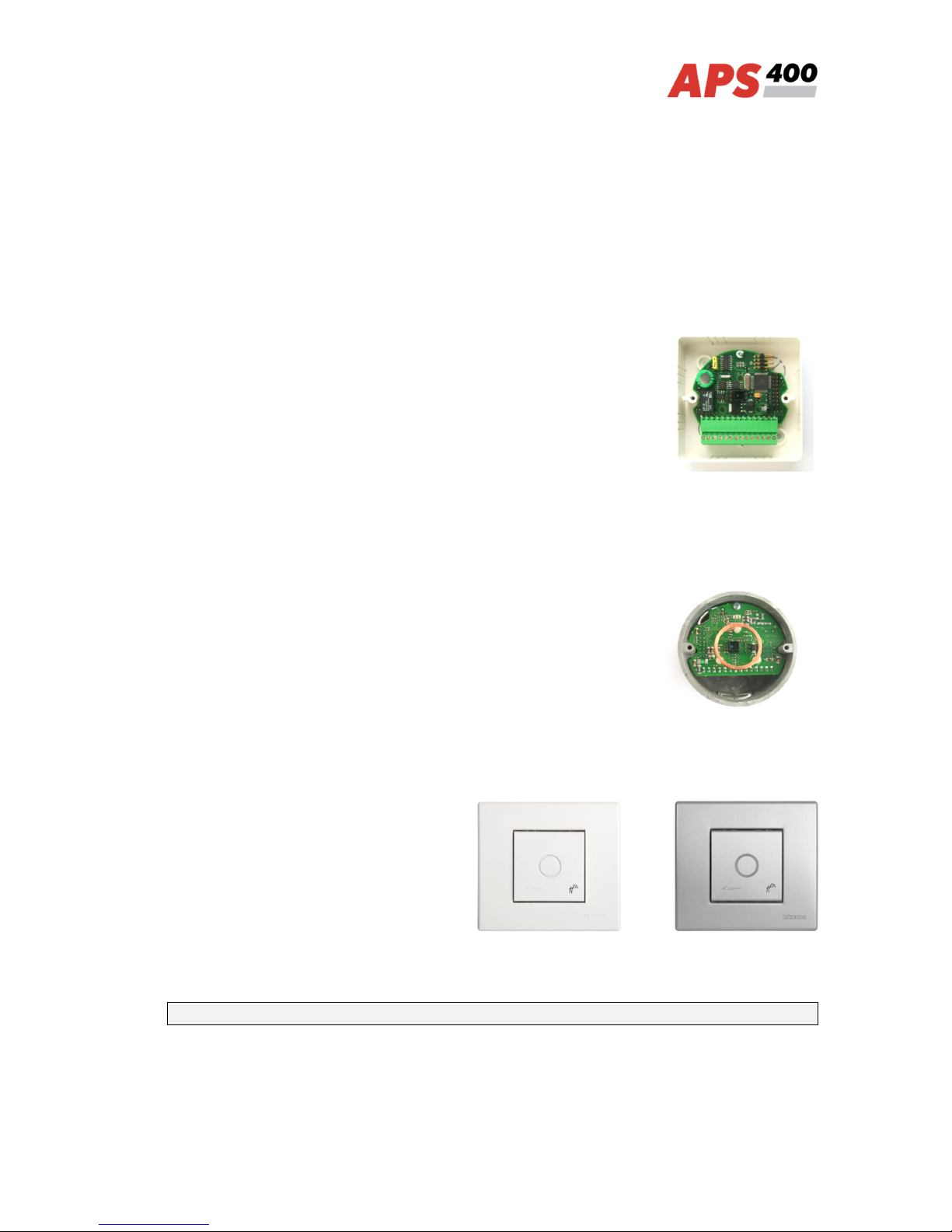
2.1 NREM 76 module
Reader module for general use designed for applications with
remote antenna module, see Pic.1.
The module can be installed wherever using a standard module is
inappropriate for mechanical or security reasons. Reading range is
dependent on the type of the antenna module and its frequency
tune-up; this is why it is not recommended to adjust the cable
supplied with the original antenna module.
2.2 NREM 76E module
Complete reader module designed for installation into round
installation boxes with inner diameter 68 mm. All-purpose
conception of the module’s board enables installation in the most of
electrical devices’ cover designs in blocks of flats and therefore
adjust the appearance of the reader modules to the appearance of
other devices designed by an architect (Pic.2).
2.3 NREM 76.BTW and NREM 76.BTW module
Applied reader module in an installation
box KU68 with a cover panel in Bticino
Light design in white (NREM 76.BTW,
Pic. 3a) or silver (NREM 76.BTS, Pic.3b)
color.
1)
Commercial designation of available versions is described in table 1.
Pic. 1: NREM 76 without cover
Pic. 2: NREM 76E+KU68 box
Pic. 3 a: NREM 76.BTW Pic. 3 b: NREM 76.BTS

Page 4
3 Technical parameters
3.1 Product version
Product version
Product designation Product housing
Catalogue
number
Module features
2)
TF
EM
HID
NREM 76 – TF
LK 80, no antenna
54476200
NREM 76E – TF
Designed for KU 68
54476000
NREM 76.BTS – TF
Bticino Light - Silver
54476400
NREM 76.BTW – TF
Bticino Light - White
54476600
NREM 76 – EM
LK 80, no antenna
54476201
NREM 76E – EM
Designed for KU 68
54476001
NREM 76.BTS – EM
Bticino Light - Silver
54476401
NREM 76.BTW – EM
Bticino Light - White
54476601
Table 1: Product version
2)
TF – TECHFASS factory ID media reading; EM – EM Marin ID media reading; HID –
HID Proximity ID media reading
3.2 Technical features
Functional Properties
Supply voltage 8 ÷ 15 VDC
Current demand
Typical 95 mA
Maximal 130 mA
Version with keypad N/A
ID technology,
typical reading range 3)
EM Marin 6 cm (with ISO card)
HID Proximity 4 cm (with ISO card
Memory 750 ID (for emergency function)
Inputs 2x logical potential-free contact
Outputs
Relay NC/NO, 2A/24V
Transistor output 5V/5mA + yellow LED
I/O Port External device
Ext. tamper / ext. reader buzzer control /
Reading synchronization: MASTER /
SLAVE mode
Indicators
3x LED
1x PIEZO
Tamper protection Opto-electronic
Communication interface RS 485 – APS BUS
Alternative data output WIEGAND (configurable)
Table 2: Technical features
3)
The reading range of MREM 76 product versions without embedded antenna is
dependent on the type of used external antenna.

Page 5
3.3 Special accessories
Special accessories
AEM 12 51400300 Antenna module for hidden assembly (no buzzer or LED)
AEM 12.1 51400301 Antenna module for hidden assembly (buzzer present, no LED)
AEM 13 51400400 Antenna module with a ferrite coil for Targha panels
WIO 22 51901200 Remote control module, 2x relay
3.4 Using WIO 22 module for remote output control
The WIO 22 remote control WIEGAND relay module is designated for secure output control
of APS system reader modules. The door open or other functions can be controlled from
the module located inside the secure area, while the reader module can be located in the
non-secure area.
The module is controller by WIEGAND signal directly from the reader module working in
standard operating mode. The module must be paired with appropriate reader module
before use.
Table 3: Special accessories

Page 6
3.5 NREM 76 mechanical design
Design
Weight 0.033 kg
Operating temperature
-10°C +40°C
Humidity Max. 75%, non-condensing
Environment Indoor
Dimensions 81x81x25 mm
Table 4 a): NREM 76 mechanical design
3.6 NREM 76E mechanical design
Design
Weight 0.018 kg
Operating temperature
-10°C +40°C
Humidity Max. 75%, non-condensing
Cover According to used installation box
Dimensions Suitable for Ø 68 mm installation boxes
Table 4 b): NREM 76E mechanical design
3.7 NREM 76.BTS and NREM 76.BTW mechanical design
Design
Weight 0.102 / 0.160 kg (W/S)
Operating temperature
-10°C +40°C
Humidity Max. 75%, non-condensing
Environment Indoor
Color
White (NREM 76.BTW)
Silver (NREM 76.BTS)
Dimensions 90x80x55 mm
Table 4 a): NREM 76.BTS and NREM 76.BTW mechanical design
Page 7
4 Installation
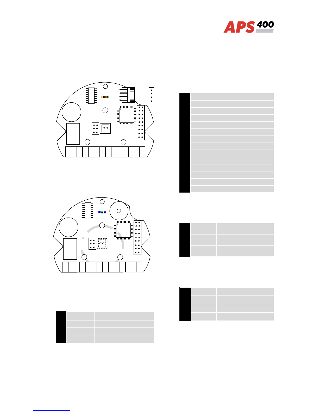
4.1 Terminals and jumpers
Pic. 5 a): NREM 76
Pic. 5 b): NREM 76E, NREM 76.BTW,
NREM 76.BTS
Address X2
X2.1 ÷ 6 HW address (A0 ÷ A5)
X2.7 Reserved
X2.8 Reserved
X2.9 Factory use
Table 5: Address jumpers X2
Terminal description X1
1 Supply voltage +13,8 V
2 Supply voltage 0 V
3 Input 1
4 0 V
5 Input 2
6 IO Port 3
7 Alarm output
8 Wiegand DATA 0
9 Wiegand DATA 1
10 A cable - RS 485 line
11 B cable - RS 485 line
12 Relay C
13 Relay NC
14 Relay NO
Table 6: Terminal description X1
RS 485 X4
150 Ω Line termination
BIAS A Idle state definition-A
BIAS B Idle state definition -B
Table 7: Line settings X4
Connector X3
ANT1 Antenna
ANT2 Antenna
BP + Buzzer (+)
BP - Buzzer (-)
Table 8: Antenna module connector X3
NO NC C B
-485
A
-485
DATA1 DATA0 AUX
IO3
IN2 IN1 GND GND +13V
1
150Ω
BIAS A
BIAS B
X4
X2 X1 1 2 3 11 12 13 14 4 5 6 7 8 9 10
NO NC C B
-485
A
-485
DATA1 DATA0
AUX
IO3
IN2 IN1 GND GND +13V
1 2 3 11 12 13
14
4 5 6 7 8 9 10
150Ω
BIAS A
BIAS B
X4
X2
X1 X3 1
ANT1 ANT2
BP +
BP -

Page 8
4.2 Standard connection (recommended, not obligatory) 4)
Connection
Input 1 Door contact, active when door closed
Input 2
Request to exit button or handle contact, active when button or
handle pressed
Output 1 Door lock control (relay)
Output 2 AUX functions (transistor output +5 V/5mA) + yellow LED
I/O Port
External tamper (Standard operating mode)
External reader buzzer control (op. mode with entry reader)
Reading synchronization: MASTER / SLAVE mode
Table 9: Standard connection
4.3 LED Indicators
LED indicators
Red
Continuously lit Online operating mode via RS 485
Blinking with 2s period Offline mode, emergency function enabled
Short flashing with 1 s period Offline mode, emergency function disabled
Green ID media reading
Yellow
Controlled by the controller’s program 4),
copies 2nd output status (AuxOutput)
Table 10: LED indicators
4)
The function of inputs and outputs is defined by user’s programming of the controller.
4.4 Installation instructions
The reader module uses passive RF/ID technology, which is sensitive to RF noise sources.
Noise sources are generally of two types: radiating or conducting.
Conducted noise comes into the reader via wires from the power supply or the host.
Sometimes, switching power supplies generate enough noise to cause reader malfunction,
it is recommended to use the linear system power suppliers.
Radiated noise is transmitted through the air. It can be caused e.g. by computer monitors
or other electrical equipment radiating electromagnetic field.
From this point of view a short distance between the reader modules themselves can
cause reading malfunctions – for correct function it is necessary to keep a minimum
distance 50 cm. Moreover, this distance can be negatively influenced by various metallic
constructions (if there are any doubts, it is useful to make a practical test before the final
mounting).
The nearby metal surfaces can cause the decreasing of reading distance and speed. This
is caused by the combined influence of parasitic capacitance and conductance.
Page 9
5 Setting parameters of the reader module
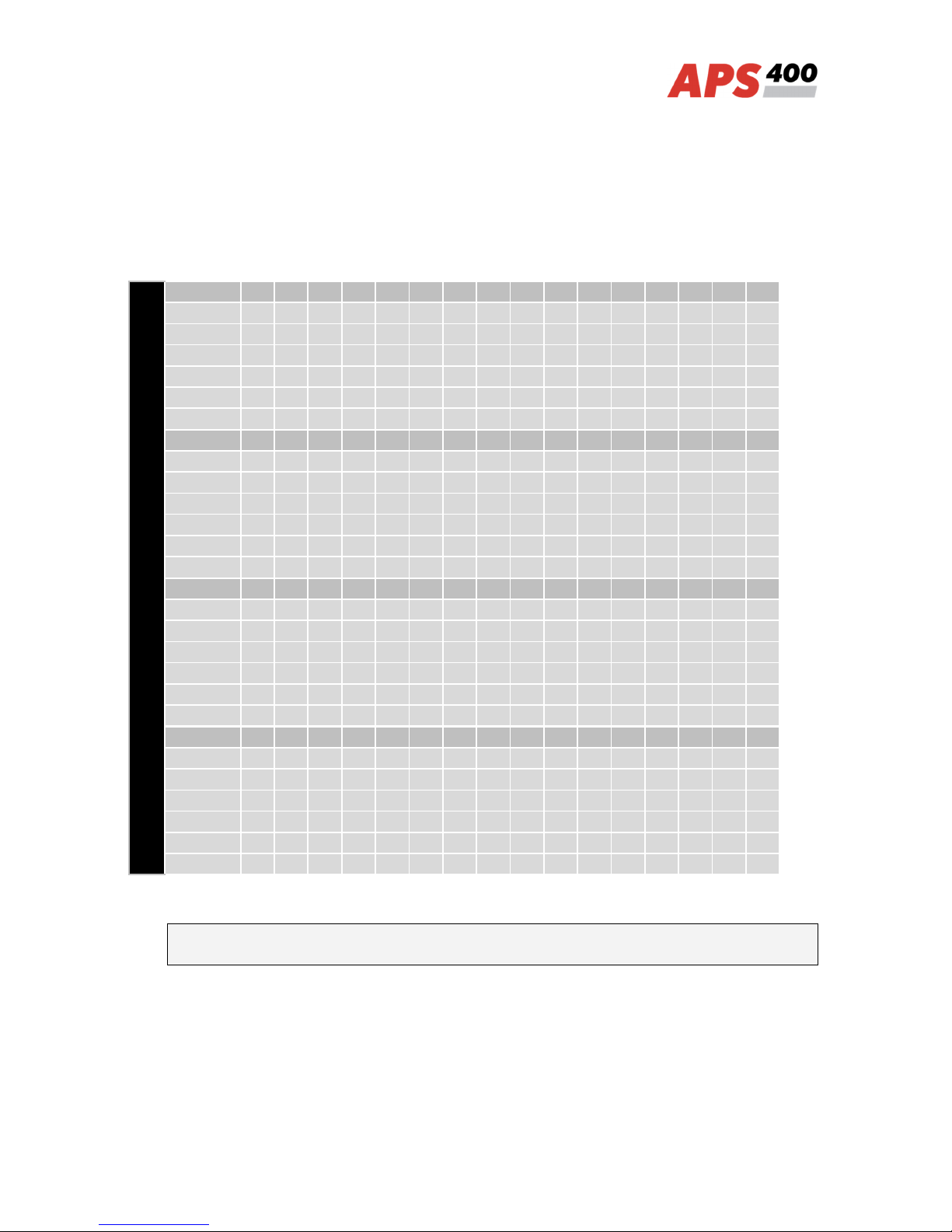
5.1 HW address setting
HW address setting is defined by the configuration of address jumpers X2.1 ÷ 6, see
tab. 11, tab. 5.
Ta
ble
11:
Ad
dre
ss
jum
per
s
X2
Leg
end
:
●
…
set
(O
N)
○
…
re
mo
ved
(O
FF)
Reader module’s reset is required after any change of address setting, disconnect and
connect the supply voltage again.
Address jumpers X2
Address
1 2 3 4 5 6 7 8 9 10 11 12 13 14 15 16
X2.1 ● ○ ● ○ ● ○ ● ○ ● ○ ● ○ ● ○ ● ○
X2.2 ○ ● ● ○ ○ ● ● ○ ○ ● ● ○ ○ ● ● ○
X2.3 ○ ○ ○ ● ● ● ● ○ ○ ○ ○ ● ● ● ● ○
X2.4 ○ ○ ○ ○ ○ ○ ○ ● ● ● ● ● ● ● ● ○
X2.5 ○ ○ ○ ○ ○ ○ ○ ○ ○ ○ ○ ○ ○ ○ ○ ●
X2.6 ○ ○ ○ ○ ○ ○ ○ ○ ○ ○ ○ ○ ○ ○ ○ ○
Address
17 18 19 20 21 22 23 24 25 26 27 28 29 30 31 32
X2.1 ● ○ ● ○ ● ○ ● ○ ● ○ ● ○ ● ○ ● ○
X2.2 ○ ● ● ○ ○ ● ● ○ ○ ● ● ○ ○ ● ● ○
X2.3 ○ ○ ○ ● ● ● ● ○ ○ ○ ○ ● ● ● ● ○
X2.4 ○ ○ ○ ○ ○ ○ ○ ● ● ● ● ● ● ● ● ○
X2.5 ● ● ● ● ● ● ● ● ● ● ● ● ● ● ● ○
X2.6 ○ ○ ○ ○ ○ ○ ○ ○ ○ ○ ○ ○ ○ ○ ○ ●
Address
33 34 35 36 37 38 39 40 41 42 43 44 45 46 47 48
X2.1 ● ○ ● ○ ● ○ ● ○ ● ○ ● ○ ● ○ ● ○
X2.2 ○ ● ● ○ ○ ● ● ○ ○ ● ● ○ ○ ● ● ○
X2.3 ○ ○ ○ ● ● ● ● ○ ○ ○ ○ ● ● ● ● ○
X2.4 ○ ○ ○ ○ ○ ○ ○ ● ● ● ● ● ● ● ● ○
X2.5 ○ ○ ○ ○ ○ ○ ○ ○ ○ ○ ○ ○ ○ ○ ○ ●
X2.6 ● ● ● ● ● ● ● ● ● ● ● ● ● ● ● ●
Address
49 50 51 52 53 54 55 56 57 58 59 60 61 62 63 64
X2.1 ● ○ ● ○ ● ○ ● ○ ● ○ ● ○ ● ○ ● ○
X2.2 ○ ● ● ○ ○ ● ● ○ ○ ● ● ○ ○ ● ● ○
X2.3 ○ ○ ○ ● ● ● ● ○ ○ ○ ○ ● ● ● ● ○
X2.4
○
○ ○ ○ ○ ○ ○ ● ● ● ● ● ● ● ● ○
X2.5 ● ● ● ● ● ● ● ● ● ● ● ● ● ● ● ○
X2.6 ● ● ● ● ● ● ● ● ● ● ● ● ● ● ● ○

Page 10
5.2 Configurable parameters
Parameters
Parameter Possible range Default setting
Enabling of emergency function YES / NO NO
Address on a communication line
1 64
1
Internal reader configuration Configurable Standard
Operating mode
Standard / Wiegand Input /
Wiegand Output
Standard
All parameters are given by programming through the MCA 168 control module, see
http://www.techfass.cz/files/aps_400_config_en.pdf
Table 12: Configurable parameters
5.3 Reader module parameters setting
Setting of all parameters of the reader module can be done only when the module is
connected to the system bus of MCA 168 controller. Detailed instructions for setting reader
module parameters are described in the APS 400 Network Reader configuration program
user’s guide available at: http://www.techfass.cz/files/m_aps_400_network_reader_en.pdf.
6 Reader module functioning
6.1 Operating modes
The NREM 76 reader modules are intended for online operating mode on APS 400 system
BUS (APS BUS). The activity of the modules is defined by the system controller; so the
modules are able to provide various functions not only controlling of the door.
In case of the communication line fails the modules can work in offline mode (when the
emergency function is enabled) - it concerns the exit readers mostly. The “Door Open“
function for last 750 valid cards registered before can be performed in this mode only.
6.2 Emergency “Door Open” function description
When the “Door Open“ function is activated, the door lock is released and the beeper
activated until the door is open or 5 s preset door lock release time has elapsed.
All events triggered while the offline mode is in progress are saved neither in the
controller nor in the reader memory.

Page 11
6.3 Read ID media format
6.3.1 EM Marin ID media format
The EM Marin ID media format can be changed into selected 24, 32 or 40 bits length of ID
code. The default length is 40 bits. This setting is only changed when unifying of the ID
media codes length is required – in combined systems with WIEGAND output readers with
a fixed WIEGAND data format IDs (more information in APS 400 Network Reader user’s
guide available at http://www.techfass.cz/files/m_aps_400_network_reader_en.pdf).
6.3.2 HID Proximity ID media format
When working with HID Proximity technology ID media, the module operates with a code in
a recognized 26 or 32 bit format, in other cases it uses all 45 bits of a media (45bit raw
format). If a specific format of the HID Proximity IDs is required, it can be performed by
setting up the user’s configuration of read IDs (more information in APS 400 Network
Reader user’s guide at http://www.techfass.cz/files/m_aps_400_network_reader_en.pdf).
6.4 Wiegand interface configuration
6.4.1 Standard operating mode
This is the module default operating mode. The Wiegand interface is used for controlling
the WIO 22 module in this configuration. When the reader module operates in the standard
operating mode, the I/O Port (tab. 6) is used as an input for monitoring an external device
tamper status.
6.4.2 Wiegand output
The module can be configured into a standard reader with a WIEGAND output in 26, 32, 42
or 44 bits format for EM Marin technology ID media. Read IDs are formatted with the
previous setting first (see chapter 6.3.1), after that they are sent in the output format. The
HID Proximity ID media are sent in the same format as set for the standard operating
mode. When the reader module operates in the Wiegand output operating mode, the I/O
Port (tab. 6) is used as an input for monitoring an external device tamper status.
Wiegand
ID media technology Available configuration of the WIEGAND output format
EM Marin 26bit, 32bit, 42bit, 44bit
HID Proximity
Automatically recognized format / 45bit raw data
User configuration
Table 13: ID media format in WIEGAND operating mode
Two long beeps and the red LED lit feature powering up the module. The green LED blink
indicates an ID reading.

Page 12
Individual signals function in WIEGAND output operating mode is described in table 14.
Wiegand
Input 1 Beeper control (0 V active)
Input 2 Yellow LED control (0 V active)
Output 1 (relay)
Tamper signaling; it follows the alarm state of tamper
sensors (tamper signal = relay switched on)
3)
Table 14: Signal function in WIEGAND operating mode
Since the FW version 2.79 the reading synchronization of a couple of TECHFASS readers
is implemented, enabling to cancel the mutual disturbance of the modules. The reader
module offers the Wiegand data interface synchronization in MASTER mode.
6.4.3 Wiegand input (entry reader)
The module can be configured into a mode of controlling the door from both sides (entry
reader mode).
In the entry reader mode an identification at an external reader connected via the
WIEGAND interface acquires a reason code 255; at the same time the reader module
operates standardly, the reason codes equal zero.
When the reader module operates in the entry reader operating mode, the I/O Port (tab. 6)
is used as an output for controlling the entry reader buzzer.
Since the FW version 2.79 the reading synchronization of a couple of TECHFASS readers
is implemented, enabling to cancel the mutual disturbance of the modules. The reader
module offers the Wiegand data interface synchronization in SLAVE mode.
The WIEGAND input and WIEGAND output operating modes are mutually exclusive.
6.5 Reading synchronization
Since the FW version 2.79 the reading synchronization of a couple of TECHFASS readers
is implemented, enabling to cancel the mutual disturbance of the modules. The reader
module offers to use the IO synchronization in both MASTER and SLAVE mode. The
input/output port 3 is used as the synchronization signal.
7 Useful links
Wiring diagrams: http://techfass.cz/diagrams-aps-400-en.html
Program equipment: http://techfass.cz/software-and-documentation-en.html
 Loading...