

Page 1
ST-292 User’s manual
1
User’s manual
ST-292 v1-v4
Page 2

TECH
2
Table of contents
I. Safety ...................................................................................................................... 3
II. Description of the device ......................................................................................... 4
III. Installation ............................................................................................................ 5
III.a) Connection diagrams (v1 and v3 versions) .............................................................. 6
IV. Receiver for wireless controller ................................................................................ 7
V. External temperature sensor ....................................................................................... 8
VI. First start-up ......................................................................................................... 9
VII. How to use the controller ...................................................................................... 10
VII.a) Principle of operation ......................................................................................... 10
VII.b) Operation modes............................................................................................... 10
VII.b) Main screen view and description ........................................................................ 13
VII.c) Controller functions ........................................................................................... 15
V.c.1) Block diagram – main menu ............................................................................ 15
VII.c.2) Day of the week .......................................................................................... 16
VII.c.3) Time settings .............................................................................................. 16
VII.c.4) Day from… .................................................................................................. 16
VII.c.5) Night from… ................................................................................................ 16
VII.c.6) Optimum start............................................................................................. 17
VII.c.7) Service menu .............................................................................................. 17
VII.c.8) Weekly control ............................................................................................ 19
VII.c.9) Floor sensor ................................................................................................ 21
VII.c.10) Maximum floor temperature ........................................................................ 21
VII.c.11) Floor temperature hysteresis ....................................................................... 22
VII.c.12) Minimum floor temperature ......................................................................... 22
VII.c.13) Pre-set comfort temperature ....................................................................... 23
VII.c.14) Pre-set economical temperature .................................................................. 23
VII.c.15) Pre-set temperature hysteresis .................................................................... 23
VII.c.16) Temperature sensor calibration ................................................................... 23
VIII. Technical data .................................................................................................. 24
Page 3
ST-292 User’s manual
3
I. Safety
Before using the device for the first time the user should read the following regulations carefully.
Not obeying the rules included in this manual may lead to personal injuries or controller damage.
The user’s manual should be stored in a safe place for further reference. In order to avoid
accidents and errors it should be ensured that every person using the device has familiarized
themselves with the principle of operation as well as security functions of the controller. If the
device is to be sold or put in a different place, make sure that the user’s manual is there with the
device so that any potential user has access to essential information about the device.
The manufacturer does not accept responsibility for any injuries or damage resulting from
negligence; therefore, users are obliged to take the necessary safety measures listed in this
manual to protect their lives and property.
WARNING
The device should be installed by a qualified electrician.
The regulator should not be operated by children.
WARNING
Any use other than specified by the manufacturer is forbidden.
Before and during the heating season, the controller should be checked for condition of its
cables. The user should also check if the controller is properly mounted and clean it if dusty
or dirty.
Care for the natural environment is our priority. Being aware of the fact that
we manufacture electronic devices obligates us to dispose of used elements
and electronic equipment in a manner which is safe for nature. As a result,
the company has received a registry number assigned by the Main Inspector
of Environmental Protection. The symbol of a crossed out rubbish bin on a
product means that the product must not be thrown out to ordinary waste
bins. By segregating waste intended for recycling, we help protect the natural
environment. It is the user's responsibility to transfer waste electrical and
electronic equipment to the selected collection point for recycling of waste
generated from electronic and electrical equipment.
Page 4

TECH
4
II. Description of the device
ST-292 room regulator is intended for controlling the heating or cooling device (e.g. gas, oil or
electric furnace or the CH boiler controller). Its main task is to maintain the pre-set temperature in
the flat by sending a signal to the heating/cooling device (contact opening) when the desired
temperature is reached.
Advanced software enables the regulator to fulfil a wide range of functions:
maintaining the pre-set room temperature
manual mode
day/night program
weekly control
control of the underfloor heating system (optional; an additional temperature sensor is
necessary)
Controller equipment:
touch buttons
front panel made of 3mm glass
built-in temperature sensor
batteries
Controller versions:
v2 – wireless, with temporary backlight. It may be optionally equipped with a wireless
external sensor. This controller version cooperates with an additional signal receiver,
installed near the heating device.
v3 – wired, with temporary backlight.
v4 – wireless, intended for cooperation with an external controller (e.g. ST-266, ST-268)
Page 5
ST-292 User’s manual
5
III. Installation
The controller should be installed by a qualified person.
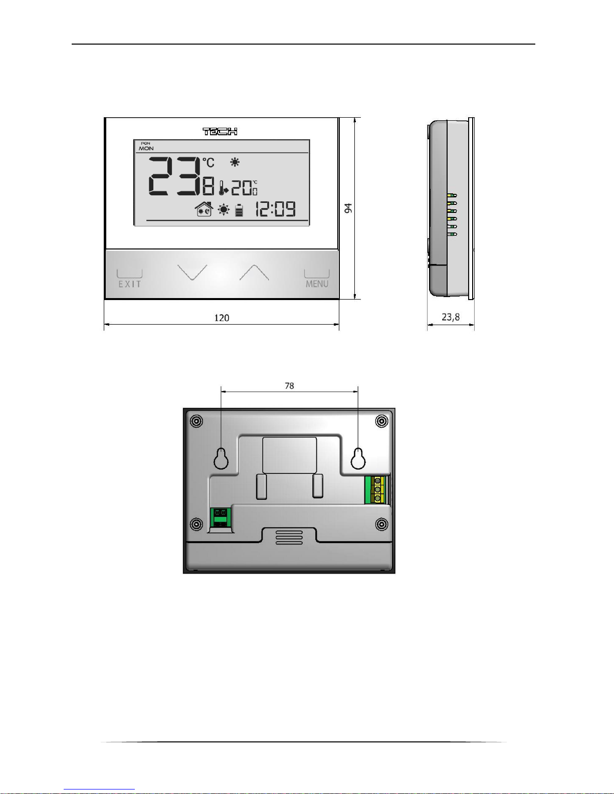
ST-292 controller may be installed as a panel mountable on the wall.
Page 6
TECH
6
III.a) Connection diagrams (v1 and v3 versions)
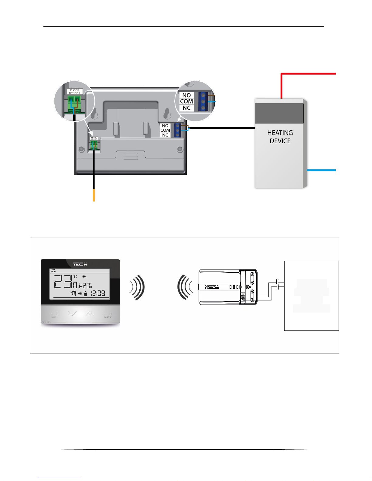
The room regulator should be connected to the heating device via a two-core cable. When
connecting devices with over 1A load, it is necessary to use a contactor. Optionally, it is possible
to connect an additional sensor to the floor sensor contact – additional functions will appear in the
controller menu.
In the case of wireless connection, use the diagram below – the two-core communication cable
must be connected to appropriate sockets in the receiver.
Heating
device or
boiler
controller
Page 7
ST-292 User’s manual
7
IV. Receiver for wireless controller
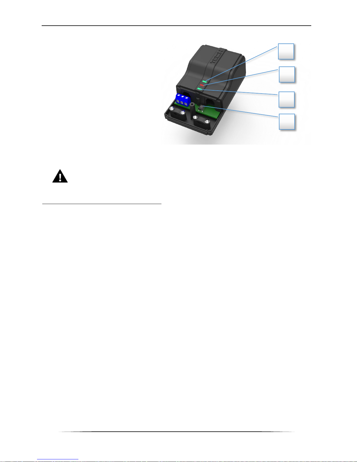
ST-292v2 regulator communicates with
the heating device (or the CH boiler
controller) via radio signal sent to the
receiver. The receiver is connected to the
heating device (or CH boiler controller)
via a two-core cable whereas the
communication with the room regulator is
performed wirelessly via radio signal.
The receiver has the following control
lights:
• green 1 (1)– indicates data reception,
goes on during channel change;
• red (2)– indicates receiver operation;
• green 2 (3) – goes on when the room
temperature fails to reach the pre-set value – the heating device is switched on.
NOTE
In case of communication failure (e.g. when the battery is flat), the receiver
automatically disconnects the heating device after 15 minutes.
How to change the communication channel
Channel “35” is the default communication channel in the room regulator. The channel may be
easily changed (if the current channel is used by other devices). To change the channel, press
and hold the channel change button (4) for about 10 seconds until the green control light (1) goes
on. Next, change the communication channel in the room regulator following the procedure
described in part VIII.c.10. The green light on the receiver should go off.
1 2 3
4
Page 8
TECH
8
V. External temperature sensor
ST-292v2 room regulator may optionally be equipped with an external temperature sensor. The
sensor should be mounted in a shaded place so that it is not affected by the weather conditions.
The current temperature value will be sent to the room regulator every few minutes and it will be
displayed on the main screen.
The external sensor communicates with the room regulator via radio signal. Both the room
regulator and the external sensor are pre-configured to operate on channel “35”, but the user
may easily change the channel (if the current channel is used by other devices).
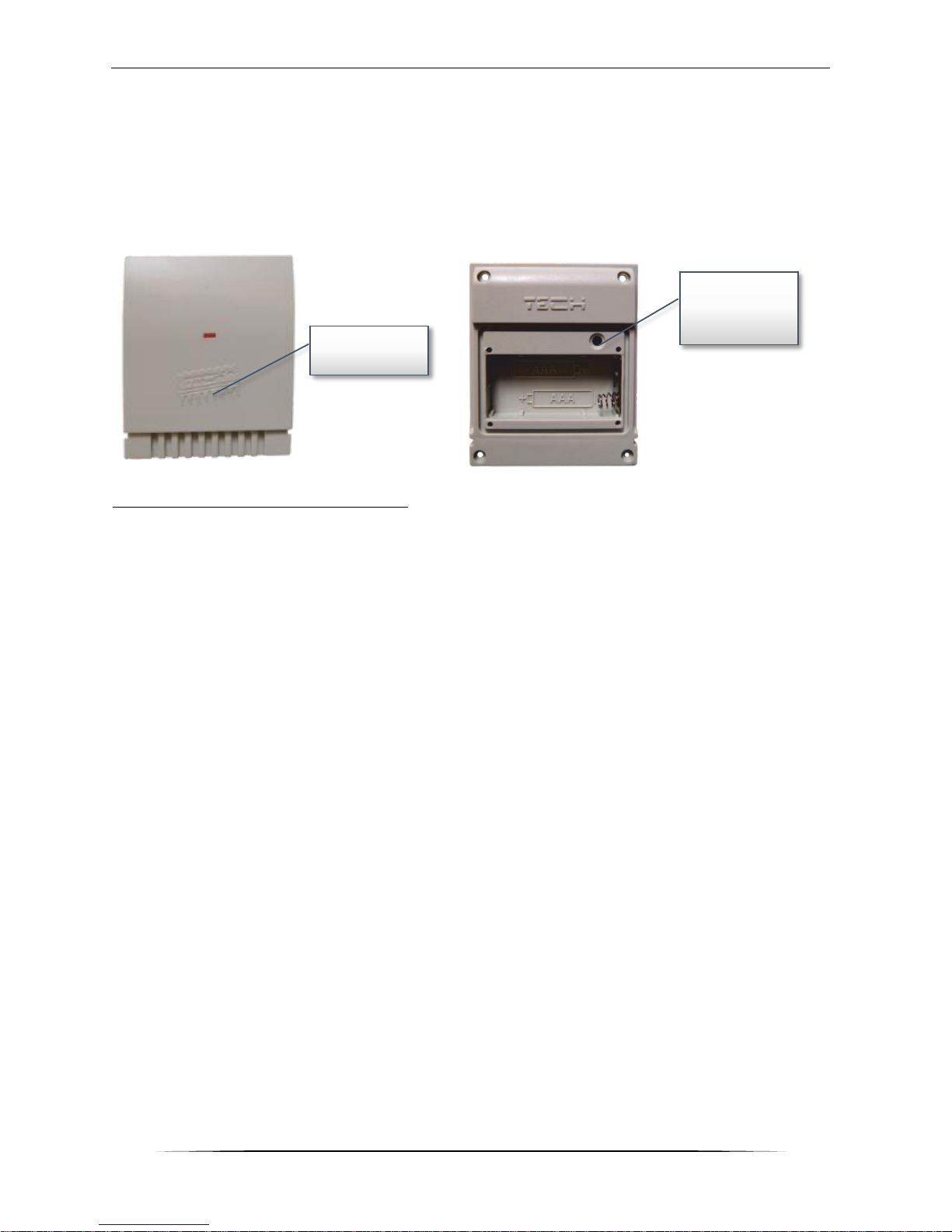
How to change communication channel:
In order to change the channel, press and hold the channel change button. After the control light
on the sensor flashes, the process of channel change has been initiated. Hold the button and wait
until the light starts flashing again. The number of flashes corresponds to the first digit of the
desired channel number.
Release the button after the desired number of flashes and press it again to set the second digit
of the channel number – the control light flashes quickly twice. Hold the button and wait until the
light flashes the desired number of times. When the button is released, the control light flashes
twice – the new communication channel has been set.
NOTE: In case of a one-digit channel number (channels 0÷9) set 0 as the first digit.
Example 1:
28 is the desired communication channel. In order to select this channel, set the first digit - 2,
and the second digit – 8.
Press and hold the channel change button - the control light flashes quickly once - the process of
channel change has been initiated. Hold the button and wait until the light flashes two more times
(the first digit of the channel number – 28).
Release the button and press it again – the control light flashes quickly twice – the process of
setting the second digit has been initiated. Hold the button and wait until the light flashes 8 times.
When the button is released, the control light flashes quickly twice – the new communication
channel has been successfully set.
Example 2:
7 is the desired communication channel. In order to select this channel, set the first digit - 0, and
the second digit – 7.
Press and hold the channel change button - the control light flashes quickly once - the process of
channel change has been initiated. As the first digit is 0, release the button before the control
light flashes again. Press the button again – the control light flashes quickly twice – the process
of setting the second digit has been initiated. Hold the button and wait until the light flashes 7
times (the second digit of the desired number). When the button is released, the control light
flashes quickly twice – the new communication channel has been successfully set.
In case of errors in the channel change process, the control light goes on for ca. 2 seconds. In
such a case the channel will not be changed.
Diode
Channel
change
button
Page 9

ST-292 User’s manual
9
VI. First start-up
ST-292 v2:
In order for the controller to operate correctly, the user must follow these steps when starting the
device for the first time:
1. Remove the front cover of the controller and insert the batteries.
2. If the room regulator is to control the underfloor heating system, connect the additional
sensor to the floor sensor contact.
3. In the case of ST-292v2 connect the two-core cable to appropriate sockets in the receiver.
4. Check if the current communication channel selected in the regulator is the same as in
the receiver. “35” is the default communication channel in all devices. If there is a conflict
with other devices using radio communication, the user needs to select a different
channel.
ST-292 v3:
In order for the controller to operate correctly, the user must follow these steps when starting the
device for the first time:
1. Remove the front cover of the controller and insert the batteries.
2. If the room regulator is to control the underfloor heating system, connect the additional
sensor to the floor sensor contact.
3. Connect the controller to the heating device using a two-core cable.
ST-292 v4:
In order for the controller to operate correctly, the user must follow these steps when starting the
device for the first time:
1. Insert the batteries
2. If the room regulator is to control the underfloor heating system, connect the additional
sensor to the floor sensor contact.
3. Check if the current communication channel selected in the regulator is the same as in
the external controller. “35” is the default communication channel in all devices. If there
is a conflict with other devices using radio communication, the user needs to select a
different channel.
4. Assign the room regulator to a given zone.
NOTE
One zone may only have one room regulator assigned to it. If more room regulators
are assigned to one zone, the external controller will not work properly.
Page 10
TECH
10
VII. How to use the controller
VII.a) Principle of operation
The main task of ST-292 room regulator is to maintain the pre-set temperature of the room
by sending a signal to the heating/cooling device (contact opening) when the desired temperature
is reached. In such a situation, the heating/cooling device is switched off (if the regulator is
connected to the CH boiler controller, the CH boiler enters sustain mode).
If the regulator is used in heating mode, it may cooperate with the underfloor heating sensor.
In such a case, the contact remains closed when the floor temperature is below the minimum
threshold. After the threshold value has been reached, the contact remains closed until the preset room temperature is reached. If the floor sensor temperature exceeds the maximum value,
the regulator opens the contact regardless of the current room temperature.
NOTE
In order for the underfloor heating functions to be available in the controller menu,
it is necessary to connect an additional sensor to the floor sensor contact.
VII.b) Operation modes
The user has three operation modes to choose from:
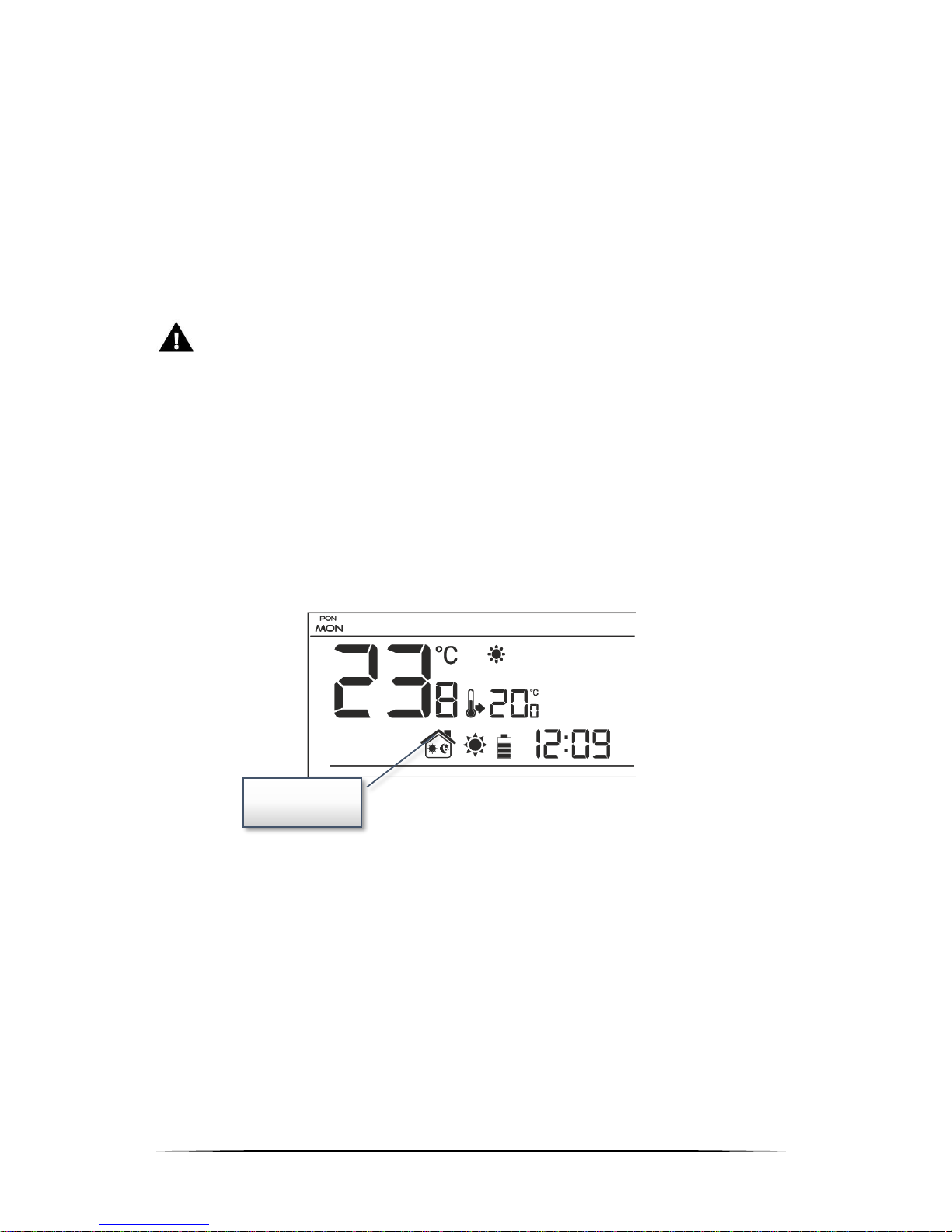
Day/night mode
In this mode the pre-set temperature value depends on the current time of the day. The user may
set different temperature values for the daytime and nighttime (comfort temperature and
economical temperature) as well as define the exact time of entering day mode and night mode.
In order to activate this mode, press EXIT button until day/night mode icon appears on the main
screen.
Day/night
mode icon
Page 11
ST-292 User’s manual
11
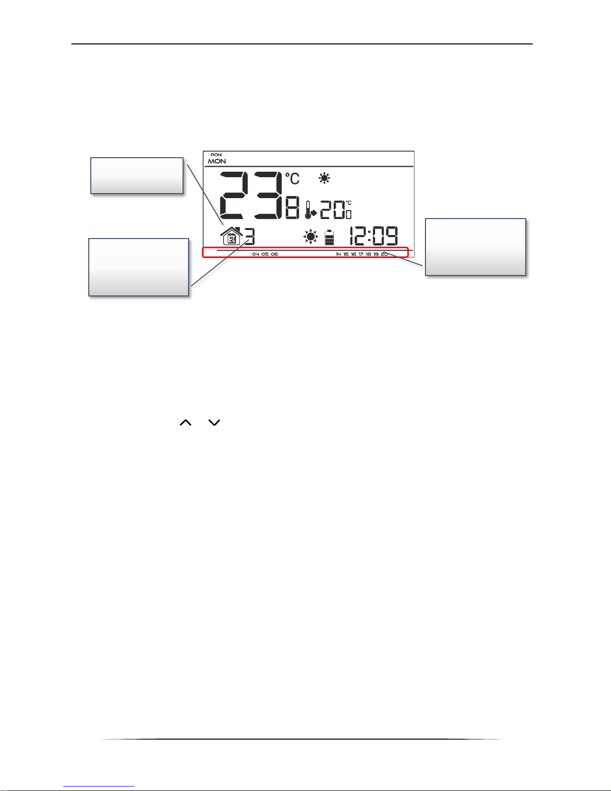
Weekly control
This mode enables the user to define the time when the pre-set comfort temperature and the preset economical temperature will apply. The user may set 9 different programs divided into three
groups:
- programs 1÷3 – daily temperature values are set for all days of the week;
- programs 4÷6 – daily temperature values are set separately for the weekdays (Monday-Friday)
and for the weekend (Saturday-Sunday);
- programs 7÷9 – daily temperature values are set for each day of the week separately.
* The display shows the hours when the comfort temperature applies. In the remaining time
period economical temperature applies.
In order to activate this mode, press and hold EXIT button until the weekly control icon appears
on the main screen.
Manual mode
In this mode the pre-set temperature is adjusted manually from the main screen view with the
use of these buttons: or . Manual mode is activated when one of these buttons is pressed.
When the manual mode is activated, the previous operation mode enters ‘sleep mode’ until the
next pre-programmed temperature change. Manual mode may be deactivated by pressing EXIT
button.
Weekly control
icon
Number of the
current weekly
control program
Parameters of the
current weekly
control program*
Page 12
TECH
12
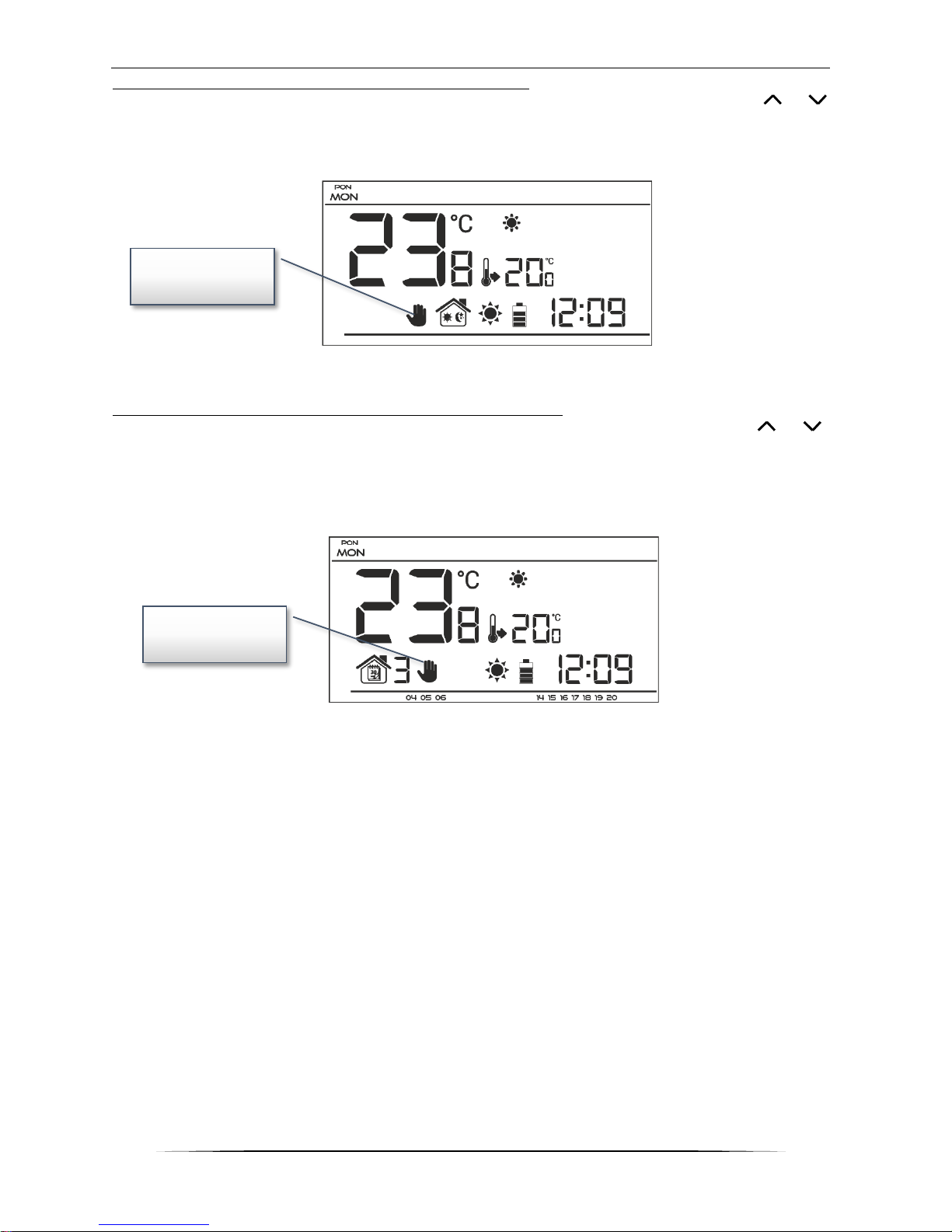
Example 1 – manual mode activation in Day/night mode
When Day/night mode is active, the user changes the pre-set temperature by pressing or
which automatically activates manual mode.
The controller returns to Day/night mode when daytime changes into nighttime (or the other way
round) or when the user presses EXIT button.
Example 2 – manual mode activation in weekly control mode
When weekly control is active, the user changes the pre-set temperature by pressing or ,
which automatically activates manual mode.
The controller returns to weekly control mode when, according to the weekly schedule, economical
temperature changes into comfort temperature (or the other way round) or when the user presses
EXIT button.
Manual mode
icon
Manual mode
icon
Page 13
ST-292 User’s manual
13
VII.b) Main screen view and description
The user operates the device using buttons. While one parameter is being edited, the remaining
icons are not displayed.
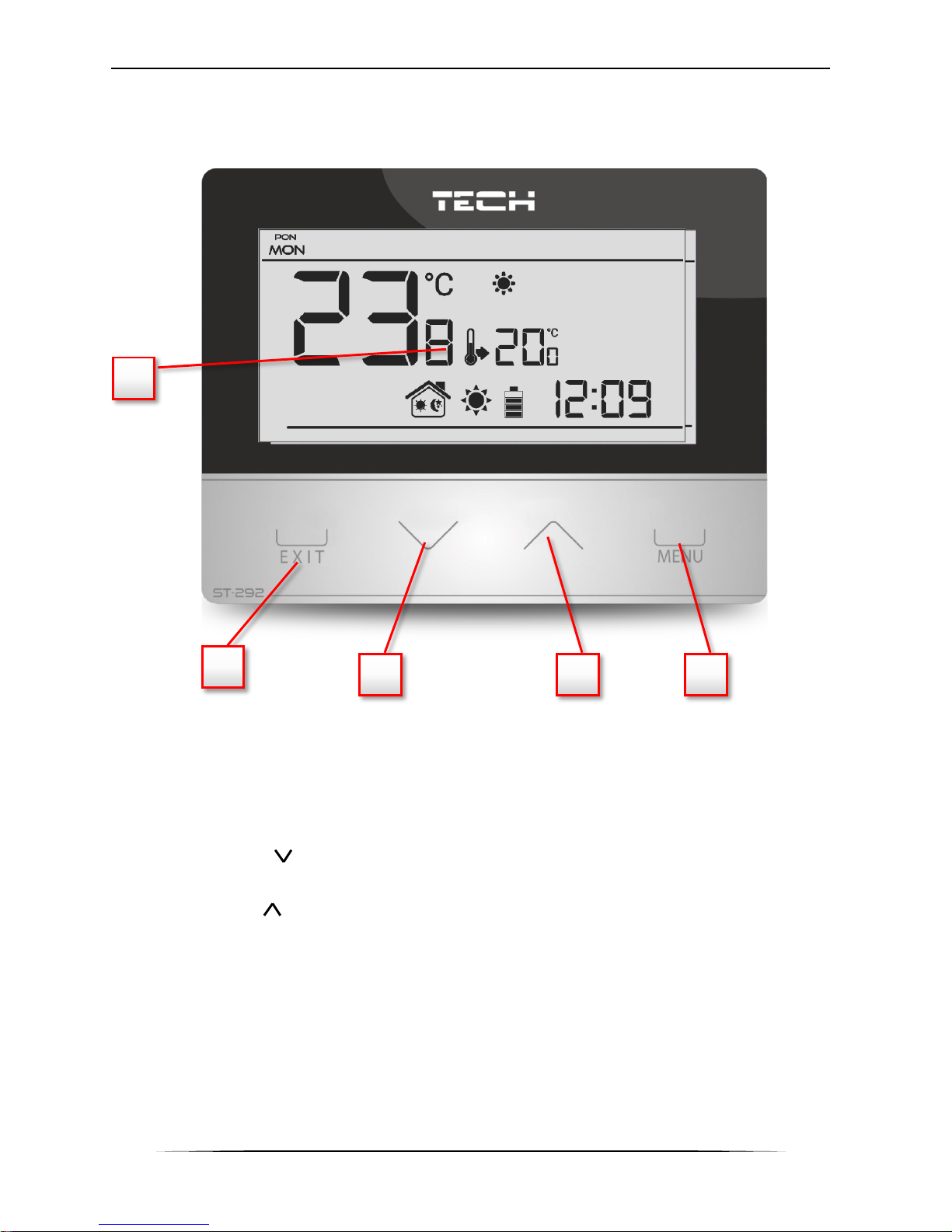
1. Display
2. EXIT - pressing this button in the main screen view activates weekly control mode or
day/night mode. After entering the menu, this button is used to confirm the settings and
return to the main screen view.
3. Minus button ( ) – pressing this button in the main screen view activates manual mode
and decreases the pre-set temperature. After entering the menu, this button is used to
adjust parameters, enter the service code etc.
4. Plus button ( ) – pressing this button in the main screen view activates manual mode
and increases the pre-set temperature. After entering the menu, this button is used to
adjust parameters, enter the service code etc.
5. MENU button – hold this button in order to enter the controller menu. While editing
parameters press this button to confirm the changes and move on to edit the next
parameter.
1
2 3 5
4
Page 14
TECH
14
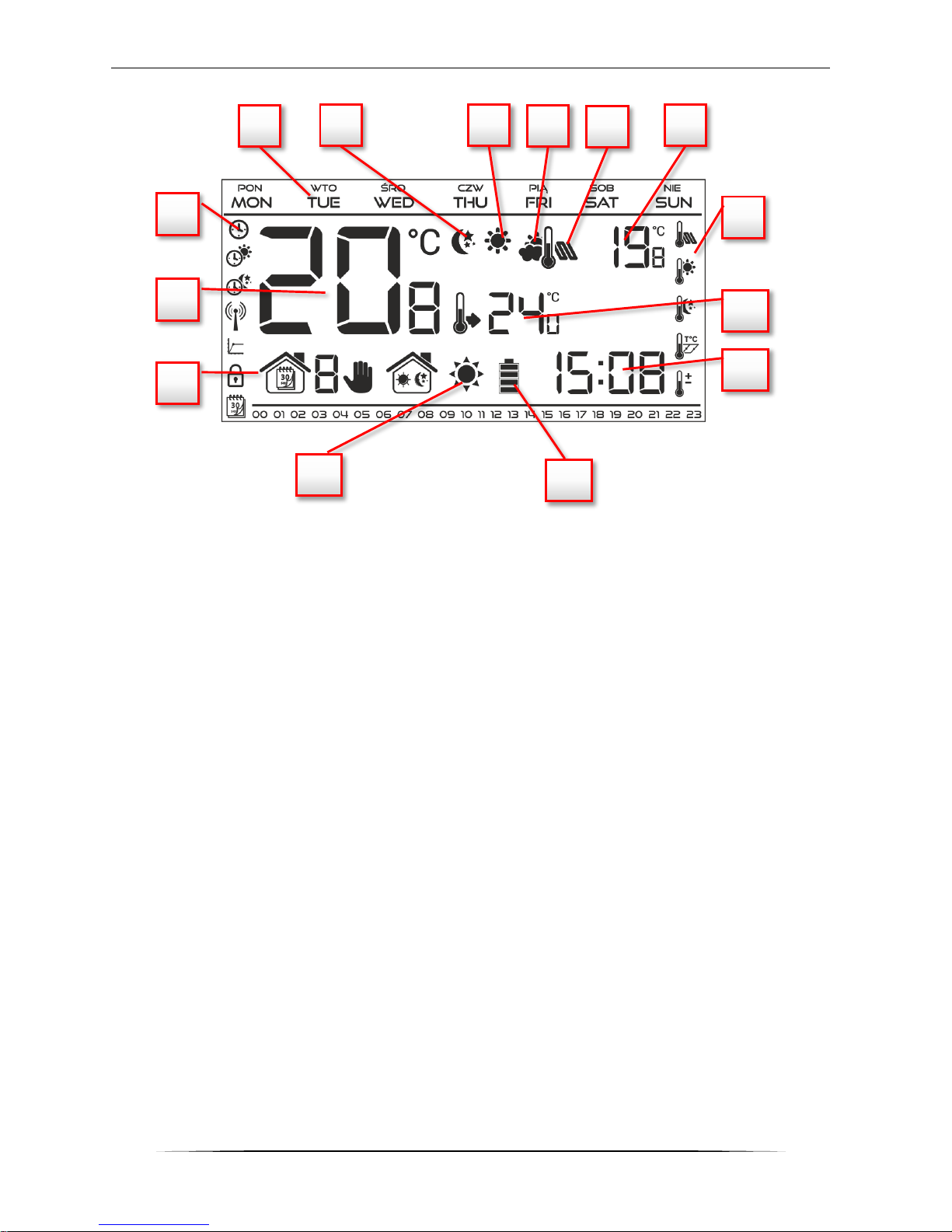
1. Current operation mode:
a. weekly
b. manual
c. day/night
2. Current temperature of the room
3. Parameters icons (see: table below)
4. Day of the week
5. Icon indicating economical temperature (according to weekly control or day/night
settings)
6. Icon indicating comfort temperature (according to weekly control or day/night settings)
7. Icon which indicates displaying current external temperature (no. 9 on the display),
active only with wireless controllers (ST-292v2, ST-292v4) or with external temperature
sensor.
8. Icon which indicates displaying current floor temperature (no. 9 on the display) – it is
necessary to connect the floor sensor and activate it in the controller menu.
9. External temperature alternately with floor temperature
10. Pre-set temperature of the room
11. Time
12. Battery level
13. Temperature information (depending on the current operation mode):
o heating mode - the icon is flashing when the pre-set temperature of the room has
not been reached and it is steady when the pre-set temperature has been reached.
o cooling mode – the icon is moving when the room temperature is above the pre-
set value and it is steady when the pre-set temperature has been reached.
1 2 3
3 5 6 4 9
10
11
12
13
7
8
Page 15
ST-292 User’s manual
15
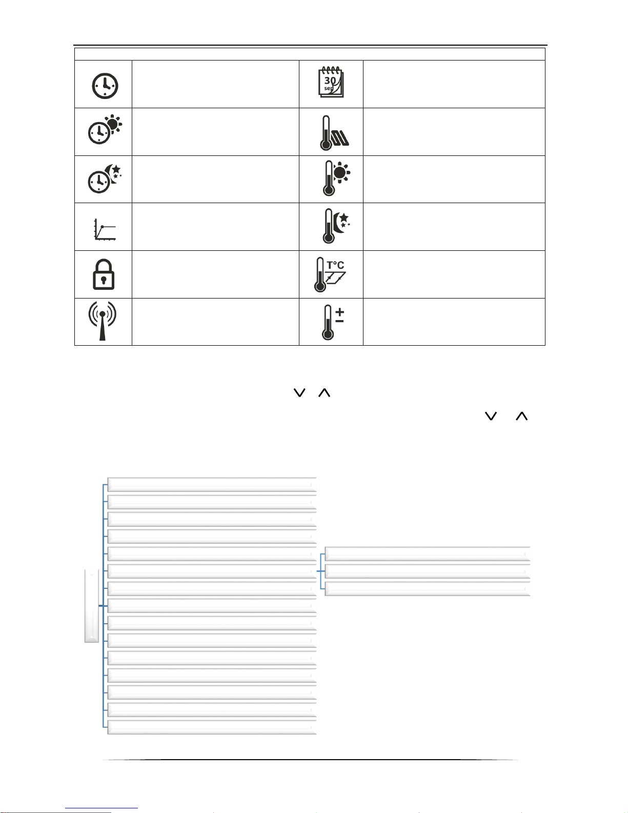
Parameters icons:
Time settings
Weekly control settings
Day from…
Floor sensor
Night from…
Comfort temperature
Optimum start / heatingcooling mode selection (in
service menu)
Economical temperature
Enter service menu / zone
selection (ST-292v4)
Hysteresis
Channel selection
Temperature sensor calibration
VII.c) Controller functions
The user navigates the menu structure using , , EXIT and MENU. In order to edit particular
parameters, press MENU. Next, press MENU to view the controller functions – the edited
parameter is flashing whereas the remaining parameters are not displayed. Use or to
change the parameter settings. Press MENU to confirm the changes and move on to edit the next
parameter or press EXIT to confirm the changes and return to the main screen view.
V.c.1) Block diagram – main menu
Main menu
Day of the week
Time settings
Day from...
Night from...
Optimum start
Service menu
Heating / cooling mode
Channel selection (ST-292 v2, ST-292 v4)
Zone selection (ST-292v4)Weekly control
Floor sensor
Maximum floor temperature*
Floor sensor hysteresis*
Minimum floor temperature*
Pre-set comfort temperature
Pre-set economical temperature
Hysteresis
Temperature sensor calibration
Page 16
TECH
16
*Functions available in the menu after the floor sensor has been activated by connecting the
additional sensor to the floor sensor contact and selecting ON in Floor sensor submenu.
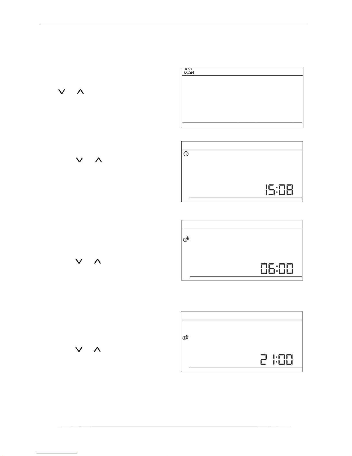
VII.c.2) Day of the week
After entering the main menu, all icons which are
not connected with the parameter which is being
edited are not displayed. The first parameter is
day of the week.
Press or until the current day of the week
is displayed. Press MENU to confirm and move on
to the next parameter or press EXIT to confirm
and return to the main screen view.
VII.c.3) Time settings
In order to set current time, press MENU until
time setting panel is displayed on the screen.
By pressing or set the hour and minutes.
Press MENU to confirm and move on to the next
parameter or press EXIT to confirm and return to
the main screen view.
VII.c.4) Day from…
This function enables the user to define the exact
time of entering the day mode. When Day/night
mode is active, comfort temperature applies at
daytime.
To configure this parameter press MENU until Day
from… setting appears on the screen.
By pressing or set the hour and minute of
day mode activation.
Press MENU to confirm and move on to the next
parameter or EXIT to confirm and return to the
main screen view
VII.c.5) Night from…
This function enables the user to define the exact
time of entering the night mode. When Day/night
mode is active, economical temperature applies
at nighttime.
To configure this parameter press MENU until
Night from… setting appears on the screen.
By pressing or set the hour and minute of
night mode activation.
Press MENU to confirm and move on to the next
parameter or press EXIT to confirm and return to
the main screen view.
Page 17
ST-292 User’s manual
17
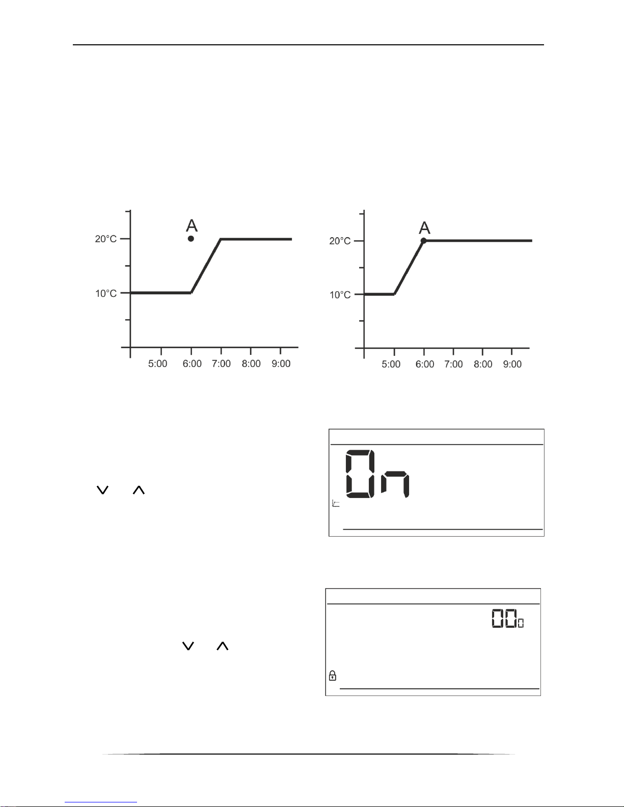
VII.c.6) Optimum start
Optimum start is an intelligent system controlling the heating/cooling process. It involves constant
monitoring of the heating/cooling system efficiency and using the information to activate the
heating/cooling process in advance in order to reach the pre-set temperatures.
The system requires no user intervention. It precisely reacts to any changes that affect
the efficiency of the heating system. If, for example, some changes have been introduced to the
heating system and the house heats up faster than before, the Optimum start system will
recognize the changes at the next pre-programmed temperature change (from comfort to
economical) and in the next cycle the heating system activation will be adequately delayed,
reducing the time needed to reach the desired temperature.
A – pre-programmed change from economical temperature to comfort temperature
Activating this function means that at the time of pre-programmed change of the pre-set
temperature from comfort to economical or the other way round, the current room temperature
is close to the desired value.
In order to configure this parameter, press MENU
until Optimum start setting panel appears on the
screen.
Use or to activate or deactivate Optimum
start function. Press MENU to confirm and move on
to edit the next parameter or press EXIT to confirm
and return to the main screen view.
VII.c.7) Service menu
Certain functions in the controller service menu are
secured with a code. In order to adjust their
parameters, press MENU until Service menu
settings appear on the screen.
To view the service menu it is necessary to enter
the code – 215. Use or to select the first
digit (2) and confirm by pressing and holding
MENU until the next digit starts flasihing. Follow
the same steps selecting the remaining two digits.
Room temperature -
OPTIMUM START switched on:
Room temperature -
OPTIMUM START switched off:
Page 18
TECH
18
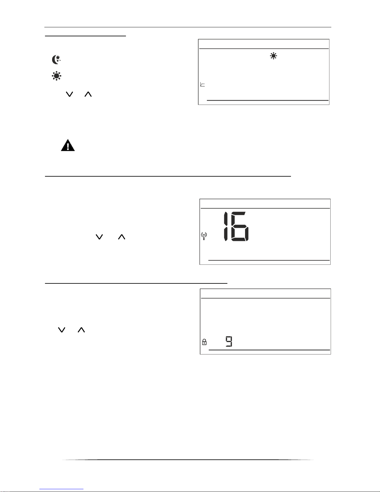
Heating/cooling mode
This function enables the user to select the room
regulator operation mode:
- controlling the cooling system
- controlling the heating system
Press or to select desired type of system.
Press MENU to confirm and move on to edit
another parameter in the service menu or press EXIT to confirm to return to the main screen
view.
WARNING
DO NOT select cooling system control if a floor sensor is used as it may damage the
underfloor heating system.
Channel selection (option available only in ST-292v2 and ST-292v4)
ST-292v2 and ST-292v4 communicates with the heating device or the CH boiler controller via a
receiver using a radio signal. For the communication to take place it is necessary to select the
same channel in both the controller and the receiver (and also in the external sensor if it is used).
Channel “35” is the default communication channel
in all devices. The channel should be changed only
if the current channel is used by other devices.
In order to change, go to service menu and press
MENU until the channel change panel appears on
the screen. Use or to select the channel.
Press MENU to confirm and move on to the next
parameter or EXIT to confirm and return to the
main screen view.
Zone selection (option available only in ST-292v4)
Assigning ST-292v4 room regulator to a selected
zone is necessary to ensure its proper cooperation
with the external controller (e.g. ST-266, ST-268).
To configure this parameter go to service menu and
press MENU until the zone selection panel appears
on the screen.
Use or to select the zone number. Press
MENU to confirm and move on to the next
parameter or press EXIT to confirm and return to
the main screen view.
Page 19
ST-292 User’s manual
19
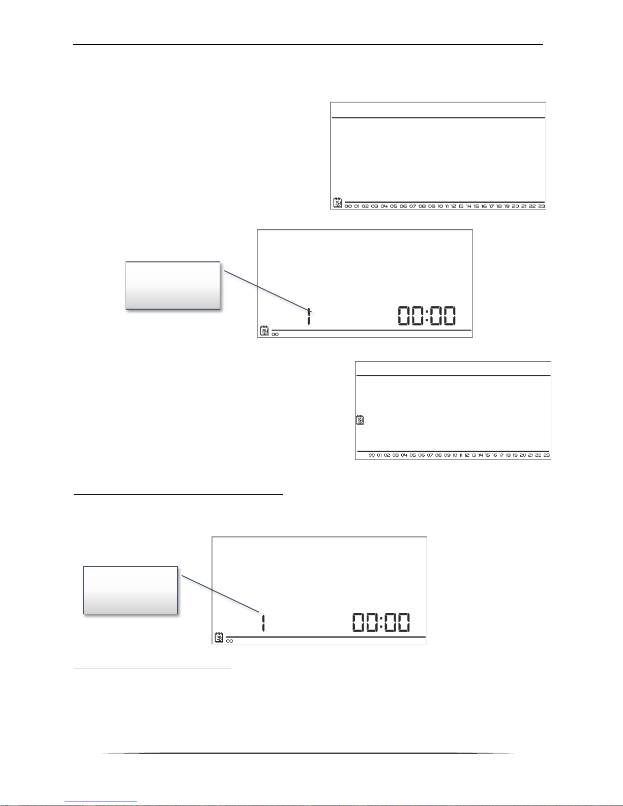
VII.c.8) Weekly control
This function is used to change the current weekly control program and edit the weekly programs.
How to change the current weekly program number
When weekly control is enabled (see: V.b Operation
modes) the current program is activated. In order
to choose the program number, press MENU until
weekly program setting appears on the screen.
By pressing and holding MENU button the user
opens the program selection panel. Each time the
user holds the MENU button, the program number
changes. When the desired number appears on the
screen, press EXIT – the controller returns to the
main screen view and the selected program number
is set.
How to configure particular weekly programs
Weekly program allows the user to define the time when
comfort temperature and economical temperature will
apply. Depending on the program number, the user may
set daily temperature values for all days of the week
(programs 1÷3), for weekdays and the weekend
separately (programs 4÷6) and for each day of the week
separately (programs 7÷9).
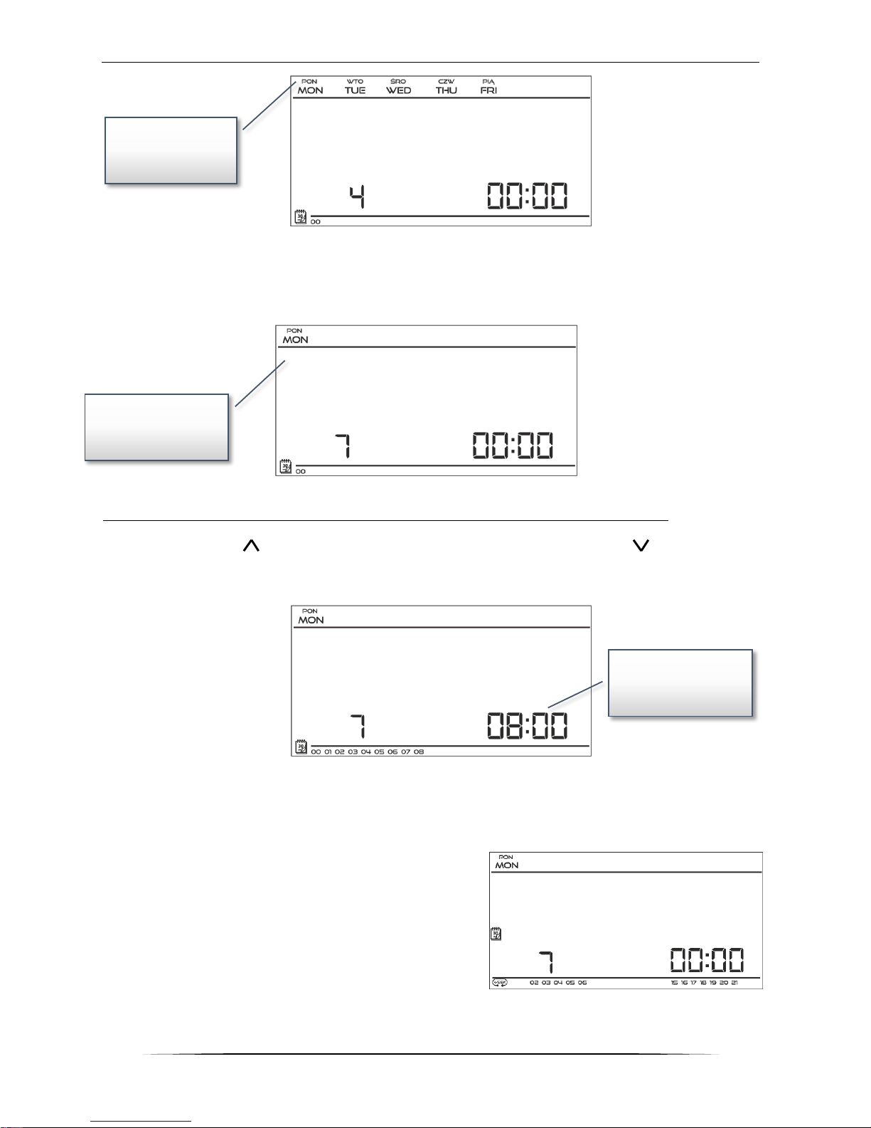
In order to edit weekly program, press MENU until weekly
program setting panel appears on the screen.
STEP 1 – choose the program to be edited:
By pressing and holding MENU button the user opens the program editing panel. Each time the
user holds the MENU button, the program number changes. When the desired number appears
on the screen, the user may start editing its parameters.
Step 2 – select days of the week
If the user wants to edit programs 1÷3, there is no possibility of selecting particular days of the
week as the setting applies to each day.
If the user wants to edit programs 4÷6 , it is possible to edit the settings for weekdays and the
weekend separately. Press MENU in order to select.
Weekly program
number
Weekly program
number
Page 20
TECH
20
If the user wants to edit programs 7÷9, it is possible to edit the settings for each day separately.
Press MENU in order to select a day.
Step 3 – assign comfort temperature or economical temperature to particular hours
An hour which is being edited is displayed on the controller screen. In order to assign comfort
temperature, press . In order to select economical temperature, press . The controller
automatically moves on to editing the next hour.
The parameters of the weekly program are displayed at the bottom of the screen: hours to which
comfort temperature has been assigned are displayed whereas hours to which economical
temperature has been assigned are not displayed.
Example:
The following screenshot presents daily settings of
program no. 7 for Monday
24⁰⁰-01⁵⁹- economical temperature
02⁰⁰-06⁵⁹- comfort temperature
07⁰⁰-14⁵⁹- economical temperature
15⁰⁰-21⁵⁹- comfort temperature
22⁰⁰-00⁵⁹- economical temperature
Editing
weekdays
parameters
Editing
parameters for
Monday
Edited hour
Page 21
ST-292 User’s manual
21
NOTE
When the user finishes the editing process by pressing and holding MENU button, the
controller returns to the main screen view and this program is selected as the current
program.
VII.c.9) Floor sensor
NOTE
This parameter is not available in the menu if the additional sensor has not been
connected to the floor sensor contact or when the cooling mode is selected.
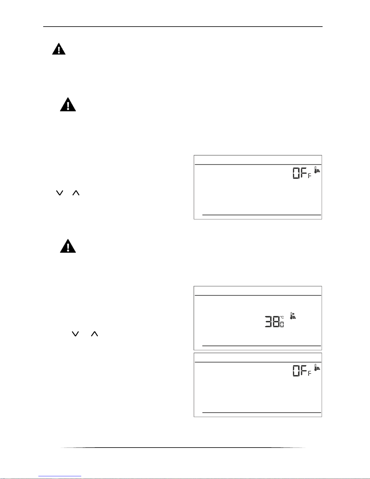
This function enables the user to activate the floor sensor. When the floor sensor is enabled, the
contact status depends also on the floor temperature. The contact remains closed (the device is
on) when the floor temperature is lower than the minimum value (regardless of the room
temperature). When the minimum temperature of the floor sensor has been exceeded, the contact
remains closed until the pre-set room temperature
is reached. If the floor sensor temperature exceeds
the maximum value, the contact is opened (the
device is disabled) regardless of the current room
temperature.
Use or to activate/deactivate the floor sensor
by selecting ON or OFF.
Press MENU to confirm and move on to edit the
next parameter or press MENU to confirm and
return to the main screen view.
NOTE
Selecting ON is necessary for the following functions to appear in the menu:
maximum floor temperature, floor sensor hysteresis and minimum floor
temperature.
VII.c.10) Maximum floor temperature
It is the floor temperature threshold. When this
threshold is exceeded, the contact opens (the
device is switched off) regardless of the current
room temperature.
Press MENU until the maximum floor temperature
panel appears on the screen (it is necessary to
activate the floor sensor beforehand by selecting
ON) Use or to select desired temperature
value.
Press MENU to confirm and move on to edit the
next parameter or press MENU to confirm and
return to the main screen view.
Page 22
TECH
22
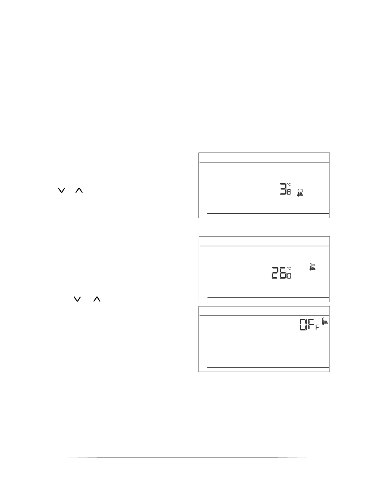
VII.c.11) Floor temperature hysteresis
Floor temperature hysteresis defines the floor temperature tolerance in order to prevent undesired
oscillation in case of small temperature fluctuation within the range of 0,4 ÷ 5°C. This parameter
concerns both the maximum and the minimum floor temperature.
Example:
Maximum floor temperature = 45°C
Hysteresis = 2°C
Minimum floor temperature = 30⁰C
The room regulator disables the contact when the temperature of 45⁰C on the floor sensor is
exceeded. When the temperature starts falling, the contact is activated again at the temperature
of 43⁰C on the floor sensor (unless the pre-set room temperature has been reached).
With the minimum floor temperature the hysteresis function works the other way round. After the
value of 30⁰C has been reached on the floor sensor, contact opening/closing depends only on the
current room temperature (reaching this value opens the contact). When the floor sensor
temperature drops to 28⁰C the contact closes regardless of the current room temperature.
In order to set the floor temperature hysteresis,
press menu until hysteresis panel appears on the
screen (floor sensor must be activated beforehand
by selecting ON)
Use or to select desired hysteresis value.
Press MENU to confirm and move on to edit the
next parameter or press MENU to confirm and
return to the main screen view.
VII.c.12) Minimum floor temperature
Minimum floor temperature concerns the
underfloor heating system operation. After this
value has been reached by the floor sensor, contact
opening and closing depends only on the current
room temperature. Below this value the contact
remains closed regardless of other factors.
Press MENU until the minimum floor temperature
panel appears on the screen (it is necessary to
activate the floor sensor beforehand by selecting
ON) Use or to select desired temperature
value.
Press MENU to confirm and move on to edit the
next parameter or press MENU to confirm and
return to the main screen view.
Page 23
ST-292 User’s manual
23
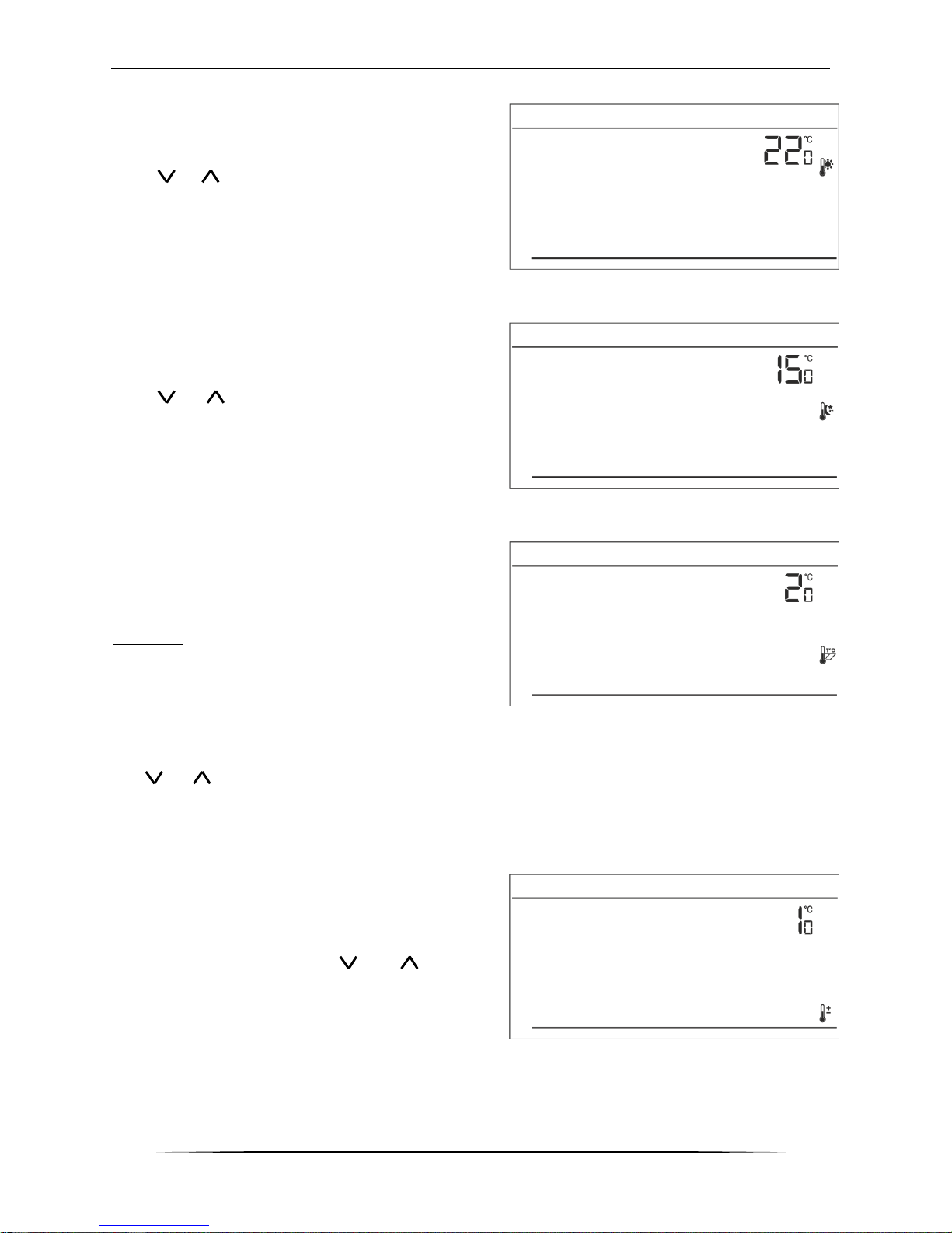
VII.c.13) Pre-set comfort temperature
Pre-set comfort temperature is used in weekly
control mode and day/night mode. Press MENU
button until the comfort temperature change panel
appears on the screen.
Press or to set the desired temperature.
Press MENU to confirm and move on to the next
parameter or press EXIT to confirm and return to
the main screen view.
VII.c.14) Pre-set economical temperature
Pre-set economical temperature is used in weekly
control mode and day/night mode. Press MENU
button until the economical temperature change
panel appears on the screen.
Press or to set the desired temperature.
Press MENU to confirm and move on to the next
parameter or press EXIT to confirm and return to the
main screen view.
VII.c.15) Pre-set temperature hysteresis
Room temperature hysteresis defines the pre-set
temperature tolerance in order to prevent undesired
oscillation in case of small temperature fluctuation
(within the range of 0,2 ÷ 4°C).
Example:
Pre-set temperature: 23°C
Hysteresis: 1°C
The room regulator reports that the temperature is
too low only when the room temperature drops to
22 °C.
In order to set the hysteresis, press MENU until the hysteresis setting appears on the screen.
Use or to set the desired hysteresis value. Press MENU to confirm and move on to the next
parameter or press EXIT to confirm and return to the main screen view.
VII.c.16) Temperature sensor calibration
It is performed when mounting the regulator or after it has been used for a long time, if the room
temperature measured by the internal sensor differs
from the actual temperature. Calibration setting
range is from -10°C to +10°C with the accuracy of
0,1°C.
Press MENU until the sensor calibration panel
appears on the screen. Use or to define
correction. Press MENU to confirm and move on to
edit the next parameter or press MENU to confirm
and return to the main screen view.
Page 24
TECH
24
VIII. Technical data
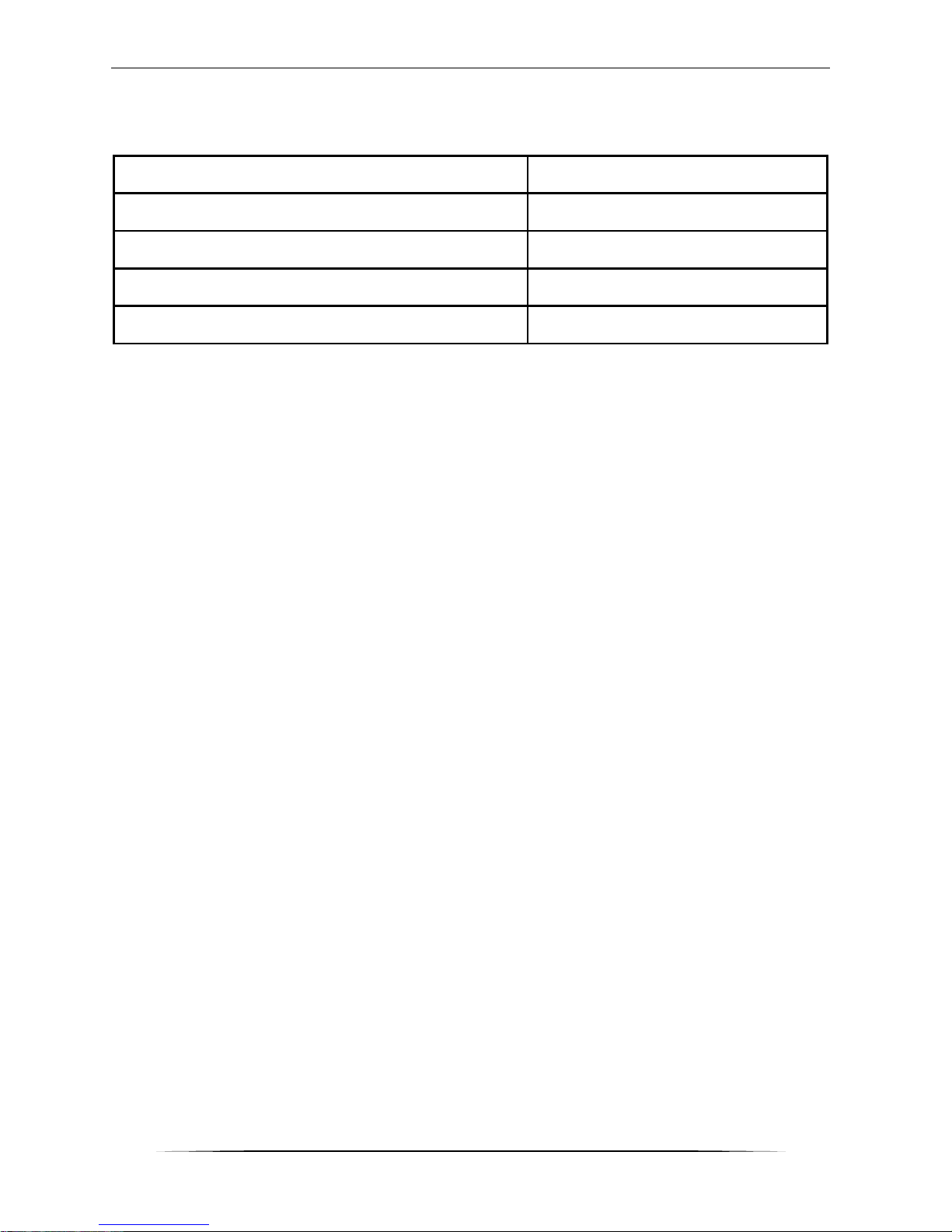
Technical data
Range of room temperature settings
5oC : 35oC
Supply voltage
Batteries 2xAA, 1,5V
Accuracy of measurement
+/- 1oC
Contact load
1A/230V/50Hz
Operating temperature
5oC : 50oC
Page 25
ST-292 User’s manual
25
EU Declaration of conformity no. 216/2016
Hereby, we declare under our sole responsibility that ST-292 v3
room regulator manufactured by TECH, headquartered in Wieprz
Biała Droga 31, 34-122 Wieprz, is compliant with:
Directive 2014/35/EU of the European Parliament and of the
Council of February 26, 2014 on the harmonisation of the laws
of Member States relating to the making available on the
market of electrical equipment designed for use within
certain voltage limits (EU Journal of Laws L 96, of
29.03.2014, p. 357),
Directive 2014/30/EU of the European Parliament and of the
Council of February 26, 2014 on the harmonisation of the laws
of Member States relating to electromagnetic compatibility
(EU Journal of Laws L 96 of 29.03.2014, p.79),
Directive 2009/125/EC establishing a framework for the
setting of ecodesign requirements for energy-related products,
the regulation by the Ministry of Economy of May 8, 2013
concerning the essential requirements as regards the restriction
of the use of certain hazardous substances in electrical and
electronic equipment, implementing provisions of RoHS
directive 2011/65/EU.
For compliance assessment, harmonized standards were used:
PN-EN 60730-2-9:2011, PN-EN 60730-1:2012.
Wieprz, 16. 05. 2016
Page 26

TECH
26
Page 27

ST-292 User’s manual
27
Page 28
TECH
28
 Loading...