


UV/VIS Spectrophotometer
UV 2600
Version: 1
INSTRUCTION
MANUAL
UV2600 UV/VIS Spectrophotometer

CONTENT
PREDACE ............................................................................................................................ 1
ABOUT THIS MANUAL ....................................................................................................... 1
PRECAUTIONS ON SAFETY ............................................................................................. 6
Chapter 1 Installation ......................................................................................................... 12
1.1 Unpacking ............................................................................................................. 12
1.2 Installation Conditions .......................................................................................... 13
1.2.1 Work Power Supply .................................................................................... 13
1.2.2 Work Table.................................................................................................. 13
1.3 Installation Environment ....................................................................................... 14
1.3.1 Operating Temperature .............................................................................. 14
1.3.2 Operating Humidity .................................................................................... 14
1.3.3 Storage Temperature .................................................................................. 14
1.3.4 Atmospheric Environment .......................................................................... 14
1.3.5 Sample Solvent .......................................................................................... 14
1.3.6 Other General Notes .................................................................................. 14
1.4 Check of Contents ................................................................................................ 15
1.5 Instrument Installation .......................................................................................... 16
1.6 Check of Voltage and Fuse .................................................................................. 16
1.7 Connection of Communication Cable................................................................... 17
1.7.1 PC Port ....................................................................................................... 17
1.7.2 Acc Port ...................................................................................................... 17
1.8 Connection of Power Cord and Grounding Wire.................................................. 17
1.9 Power On .............................................................................................................. 18
Chapter 2 Function .......................................................................................................... 19
2.1 Work Principle....................................................................................................... 19
2.2 Optical Path System ............................................................................................. 20
2.3 Circuit System ...................................................................................................... 21
2.4 Function Mode ...................................................................................................... 22
2.5 Sample Compartment........................................................................................... 23
2.6 Specifications ........................................................................................................ 24
Chapter 3 Operation .......................................................................................................... 25
3.1 Preparation ........................................................................................................... 25
3.1.1 Install Software & Connect UV2600 to PC ................................................ 25
3.1.2 Initialization ................................................................................................. 25
3.2 Basic Operation .................................................................................................... 26
3.2.1 Operation Method ...................................................................................... 26
Chapter 4 Maintenance ..................................................................................................... 28
4.1 Daily Maintenance ................................................................................................ 28
4.1.1 Cleaning of Sample Compartment ............................................................. 28
4.1.2 Clean of Spectrophotometer Cover ........................................................... 30

4.1.3 Cleaning and Storing of Cuvette ................................................................ 31
4.1.4 Add Lube .................................................................................................... 32
4.1.5 Clean of Window Frame and Lens of Sample Compartment ................. 32
4.2 Performance Verification ...................................................................................... 33
4.3 Troubleshooting .................................................................................................... 34
4.3.1 Error Information ........................................................................................ 34
4.3.2 Failure Cause and Countermeasure .......................................................... 35
4.3.3 Replacing fuses .......................................................................................... 35
4.4 Replacement of Consumable Parts ..................................................................... 36
4.4.1 Replacement of Light Source Lamp .......................................................... 36
4.4.2 Clear of Lamp Use Time ............................................................................ 41
4.4.3 Adjustment of Lamp ................................................................................... 41
4.5 Disassembly of Instrument Main Parts ................................................................. 45
4.5.1 Open Instrument Cover .............................................................................. 45
4.5.2 Removal Procedures of Power Switch ...................................................... 45
4.5.3 Removal of Control Board and Lamp Power Supply Board ...................... 46
4.5.4 Removal Procedures of Pre-amplifier ........................................................ 46
4.6 Storing of Instrument .......................................................................................... 47
4.6.1 After Test Is Finished .................................................................................. 47
4.6.2 Instrument Will Not Be Used for a Long Time ........................................... 47

PREFACE&SAFETY SUMMARY
PREFACE
Thank you very much for your purchase of Techcomp Model UV2600
UV/VIS Spectrophotometer.
The Model UV2600 Spectrophotometer is intended for the purpose of
spectral analysis. Do not use it for any other purpose.
The Model UV2600 is designed for use by persons having a basic
knowledge of chemical analysis. Other persons should operate the
instrument in the presence of someone who has such basic knowledge.
Remember that improper use of the instrument, chemicals or samples
would result not only in wrong analytical data but in consequences adverse
to safety.
Before using the instrument, be sure to read through this instruction
manual to enable correct use.
For installation/maintenance of the instrument, read the instruction manual
carefully to attain a full understanding of the instructions. Be sure to
observe cautionary instructions.
Keep this manual handy for easy reference when necessary.
Information contained in this manual is subject to change without notice for
product improvement.
ABOUT THIS MANUAL
Before using the instrument, be sure to read through this instruction
manual. First of all, read “SAFETY SUMMARY” included at the beginning
of this manual for ensuring safety in operation of the spectrophotometer
main unit.
1

PREFACE&SAFETY SUMMARY
Precautions on Electromagnetic Wave Interference
(1)Possible Electromagnetic Wave Interference Caused by This Instrument
When this instrument is used in a residential area or an adjacent area
thereto, it may cause interference to radio and television reception.
To prevent this, use the specified system connection cables in strict
accordance with the instruction manual. The instrument is designed to
minimize possible electromagnetic wave interference caused by it if the
specified cables are connected properly.
However, there is no guarantee that electromagnetic wave interference will
not be caused by the instrument. If the instrument does cause
interference to radio or television reception, which can be determined by
turning off and on the instrument, the user is encouraged to try to correct
the interference by one or more of the following measures:
Increase separation between the instrument and radio/TV receiver.
Connect the instrument to an outlet on a circuit different from that to
which the radio/TV receiver is connected.
(2)Possible Electromagnetic Wave Interference Affecting This Instrument
If this instrument is used near an intense electromagnetic source,
interference noise may be given to the instrument to incur an adverse effect
on its performance or functionality.This effect will be less than 1% and still
could be accepted.
To prevent this, use the specified system connection cables in strict
accordance with the instruction manual. The instrument is designed to
minimize possible electromagnetic wave interference affecting it if the
specified cables are connected properly.
However, there is no guarantee that electromagnetic wave interference will
not occur in this instrument. If the instrument does incur electromagnetic
wave interference, which can be determined by turning on and off possible
sources of electromagnetic wave interference nearby, the user is
encouraged to try to correct the interference by one or more of the following
measures:
Reorient the instrument.
Increase separation between the instrument and possible sources of
electromagnetic wave interference.
Increase separation between the power cable of the instrument and
possible sources of electromagnetic wave interference.
Connect the instrument to an outlet on a circuit different from that to
which possible sources of electromagnetic wave interference are
connected.
Confirm that any other device connected with the instrument is not
affected by electromagnetic wave interference.
2

PREFACE&SAFETY SUMMARY
Warranty on Product
The Model UV2600 Spectrophotometer is warranted to operate according
to the specifications given in the instruction manual, provided it is used in
accordance with the instructions described in the manual.
(1)Scope of Warranty
(a) Main unit of the instrument which prove to be defective in design or
workmanship during the warranty period will be repaired without charge.
(b) A substitute part may be used for repair, or replacement with an
equivalent product may be made instead of repair.
(c) Such system components as a personal computer and printer to be
updated frequently for improvement may not be available in original
versions at the time of replacement.
(d) The instrument can’t be provided repair for free in warranty period if it
was sold to other user.
(2)Warranty Period
One year from the date of initial installation or received by the customer (The
deadline refer to the fist one).
(3)Limitations and Exclusions on Warranty
Note that this warranty is void in the following cases, even if they occur
within the warranty period.
(a) Failure due to operation at a place not meeting the installation
requirements specified by us
(b) Failure due to power supply voltage/frequency other than specified by
us or due to abnormality in power supply
(c) Corrosion or deterioration of the tubing due to impurities contained in
reagent, gas, air or cooling water supplied by the user
(d) Corrosion of the electric circuits or deterioration of the optical elements
due to highly corrosive atmospheric gas
(e) Failure due to use of hardware, software or spare parts other than
supplied by us
(f) Failure due to improper handling or maintenance by the user
(g) Failure due to maintenance or repair by a service agent not approved
or authorized by us
3

PREFACE&SAFETY SUMMARY
(h) After disposal of this instrument, or after its resale without our approval
(i) Failure due to relocation or transport after initial installation
(j) Failure due to disassembly, modification or relocation not approved by
us
(k) Consumables, and failure of parts that have reached the end of
specified useful life
(l) Failure of parts excluded from the warranty in the instruction manual or
other documents
(m) Failure due to acts of God, including fire, earthquake, storm, lightning,
social disturbance, riot, crime, insurrection, war (declared or undeclared),
radioactive pollution, contamination with harmful substances, etc.
(n) Failure of the hardware, or damage to the system software, application
software, data or hard disk due to computer virus infection
(o) Failure of the personal computer connected with the instrument, or
damage to the system software, application software, data or hard disk
due to power interruption or momentary power voltage drop caused by
lightning or the like
(p) Failure of the personal computer connected with the instrument, or
damage to the system software, application software, data or hard disk
due to disconnection of main power to the personal computer without
taking the specified normal shutdown procedure
Warning: Class A equipments is intended for use in an industrial environment. In the
documentation for the user, a statement shall be included drawing attention to the fact that
there may be potential difficulties in ensuring electromagnetic compatibility in other
environments, due to conducted as well as radiated disturbances.
(4)Disclaimer of Warranty
(a) Any express warranties other than the explicit conditions indicated in
(1) are excluded from this warranty.
Any other implied warranties of merchantability and fitness for a particular
purpose are not included in this warranty. No liability is assumed for
direct or indirect damages arising out of explicit or implied warranties.
(b) Oral or written information or advice given by our dealers, distributors,
agents or employees without our express permission shall not create a
warranty or in any way increase the scope of this warranty.
Installation, Relocation and After-sale Technical Service
4

PREFACE&SAFETY SUMMARY
Installation of this instrument shall be carried out by or under supervision of
qualified service personnel of Techcomp Corporation or its authorized service
agent.
Before installation of the instrument, the user shall make preparations for
satisfying the installation requirements in accordance with the instruction
manual.
If relocation of the instrument becomes necessary after initial installation
(delivery), please notify your local sales representative or nearest service
office of Techcomp.
Technology Training for User
For using the instrument safely and correctly, technology training speeches are
held at Techcomp’s or user’s site. Contact Techcomp for attending procedures.
Technology training speeches are payable, it will charge fee.
Disposal of this Instrument
When you discard equipment, please check and confirm some related
statute, law and practices .or ask the service section of Techcomp.
Other Precautions
(1)Handling of Chemicals and Samples
(1) The user is responsible for following relevant legal standards and
regulations in handling, storage and discarding of chemicals and samples
used in analytical operations of this instrument.
(2) Reagents, standard solutions and accuracy-control samples shall be
handled, stored and discarded as instructed by the respective suppliers.
(2)Notice on Instruction Manuals
(1) Information contained in the instruction manuals furnished with the
instrument is subjected to change without notice for product improvement.
(2) This manual is copyrighted by Techcomp with all rights reserved.
(3) No part of this manual may be reproduced or transmitted in any form or
by any means without our express written permission.
5

PREFACE&SAFETY SUMMARY
SAFETY SUMMARY
PRECAUTIONS ON SAFETY
Before using the Model UV2600 Spectrophotometer, be sure to read the
following safety instructions carefully.
General Safety Guidelines
Follow all the operating procedures provided in this manual.
Installation and maintenance of the product shall be carried out by
service personnel qualified therefore.
Be sure to observe the warnings indicated on the product and in the
instruction manual. Failure to do so could result in personal injury or
damage to the product.
The hazard warnings which appear on the warning labels on the
product or in the manual have one of the following alert headings
consisting of an alert symbol and signal word DANGER, WARNING, or
CAUTION.
DANGER: Indicates an imminently hazardous situation which, if
not avoided, will result in death or serious injury.
(This warning does not apply to this product.)
WARNING: Indicates a potentially hazardous situation which, if
not avoided, can result in death or serious injury.
CAUTION: Indicates a hazardous situation which, if not avoided,
will or can result in minor or moderate injury, or
serious damage to the product.
: Precedes every signal word for hazard warnings, and
appears in safety-related descriptions in the manual.
“NOTICE” and “NOTE” are heading words which do not concern personal
safety directly.
NOTICE:Used to indicate an instruction for preventing damage to the
product.
NOTE: Used to indicate an instruction for ensuring correct use of the
product and accurate analysis therewith.
6

PREFACE&SAFETY SUMMARY
SAFETY SUMMARY
General Safety Guidelines
■ Do not modify the product, replace parts that are not user-
serviceable, use non-specified parts, nor remove safety devices, as it
could be hazardous.
■ Installation at delivery, maintenance and relocation should be referred
to our qualified service personnel.
■ Do not perform any operation or action other than described in the
instruction manual. When in doubt, please contact our sales
representative or service office nearest you.
■ When using a chemical for analytical operation, be sure to provide
proper ventilation in the laboratory room as per local requirements.
Inadequate ventilation could endanger human health.
Keep in mind that the hazard warnings in the manual or on the product
cannot cover every possible case, as it is impossible to predict and
evaluate circumstances beforehand.
Be alert and use your common sense.
7

PREFACE&SAFETY SUMMARY
SAFETY SUMMARY
This instruction manual contains the following cautious instructions.
DANGER
The warning “DANGER” does not apply to this product.
WARNING
Electric Shock in Contact with Dangerous High Voltage (500 V)
In contact with D2 lamp power supply voltage (500 V), you may receive an
electric shock to cause fatal or serious injury.
Before replacing the D2 lamp, make sure that the POWER switch of the
spectrophotometer main unit is turned off.
Electric Shock in Contact with Dangerous Voltage
In contact with power supply voltage (100-240V), you may receive an
electric shock to cause fatal or serious injury.
Before connecting the power cord, make sure that the POWER switch of
the spectrophotometer main unit is turned off.
CAUTION
Burn in Contact with High Temperature
The D2 lamp and WI lamp reach a high temperature.
They can burn you if touched.
Before replacing or adjusting the lamp, turn off the POWER switch and
wait until it cools down sufficiently.
Fatigue on Long Use
Watching the CRT screen in the same posture for a long time
accumulates fatigue in your eyes or body. For long use, take a 10 to
15-minute rest every hour for your health.
Oxygen Deficiency due to Presence of Nitrogen
■ If nitrogen purging is carried out for long hours in a narrow room without
operating an exhaust duct, the oxygen concentration in the room will
decrease and an oxygen deficiency could result.
Be sure to operate an exhaust duct or else open a window during the
purge for ventilation purposes.
8

PREFACE&SAFETY SUMMARY
SAFETY SUMMARY
Remarks on safety of spectrophotometer
Electricity
(a) Confirm the power supply to the spectrophotometer is AC100-240V.
(50Hz or 60Hz).Power is more than 1 KVA.
Fluctuation in voltage or noise on the power line would not only affect
the spectrophotometer main unit adversely but also cause an accident.
(b) Be sure to provide grounding connection along with power connection.
Make sure that the spectrophotometer is grounded at a grounding
resistance of 10 or less.
If grounding is improper, the spectrophotometer is easily affected by
external noise and floating voltage generated in it endangers physical
safety.
(c) High-voltage circuits are used inside the spectrophotometer.
Do not open any other cover than necessary for operation.
Fire
Avoid smoking and using a fire in the vicinity of the spectrophotometer.
Labels on spectrophotometer
There are warning labels of high pressure, high temperature on UV2600
Spectrophotometer. Pay attention to them during operation to avoid safety
accidents.
Back Up the Data
It is therefore recommended to back up the contents of the hard disk
beforehand.
To avoid misoperation, set space of more than 100 MB in computer
harddisk as work area for UV apllication software.
Computer Virus
If programs or data has suddenly been destroyed, if an unexpected
operation takes place or if an abnormal display appears on the screen,
your personal computer may have been infiltrated by a computer virus.
The computer virus is a rogue program that secretly invades a personal
computer and operates it willfully while destroying memorized data.
A program for eliminating the virus is called vaccine program.
There is a possibility of contamination with a computer virus by
downloading through communication a program including a computer
virus, or by using an exchangeable recording medium such as a floppy
disk that contains a computer virus. Also, it is possible to transmit the
9

PREFACE&SAFETY SUMMARY
virus from one personal computer to another via communication or
recording media. So avoid using a program or recording medium that
might include a virus.
Carry out check using a vaccine program if there is a possibility of
contamination with a virus. But depending on the type of vaccine
program, it may be impossible to eliminate the virus.
Personal Computer (PC)
Do not turn off the PC power supply alone. If the PC power supply is
turned off during access to the hard disk or floppy disk, the PC may
malfunction and the data or software stored in it may be destroyed. To
turn off the PC power supply, be sure to complete the spectrophotometer
control and data processing program (UV Analyst) before taking the
shutdown procedure for the system software.
Power Failure
A power failure or momentary voltage drop of the power supply due to
lightning, etc. may cause failure of the personal computer used with the
instrument and also damages the system software, application software
and other data.
To avoid such problems, it is recommended to use an AC uninterruptible
power source.
10

PREFACE&SAFETY SUMMARY
SAFETY SUMMARY
Warning Labels
The warning labels shown below are attached to the Model UV2600
Spectrophotometer.
(1) Dangerous Voltage(500V、100-240V)
The warning label above is attached to cover of lamp source compartment and power
supply socket.
(2)Attention to High Temperature
The warning label above is attached to cover of lamp source compartment.
11

CHAPTER 1 INSTALLATION
1.1 Unpacking
After opening the packing case, put the instrument onto work table with great
care. Avoid serious shock to packing case when unpacking it. Moreover, the
weight of UV2600 spectrophotometer is about 50kg. Care should be taken
when moving it.
Figure 1-1 UV2600 UV/VIS Spectrophotometer
△ Note:To avoid shock during transportation, sponge has been used for
fixing viewfinder in UV2600. Before powering on the instrument, first open
cover of light source compartment and take out sponge in viewfinder.
Otherwise, it may have influence on instrument initialization check and normal
use.
CHAPTER 1 INSTALLATION
12

CHAPTER 1 INSTALLATION
1.2 Installation Conditions
Before installing the instrument, please confirm the following installation
conditions.
1.2.1 Work Power Supply
The requirements for UV2600 work power supply are as follows:
1)Voltage:AC100-240V, fluctuation within ±10% is allowed.
2)Frequency:50Hz or 60Hz,fluctuation within ±4% is allowed.
3)Power:more than 600VA is required. If other devices share the same power
supply,it needs more than 1KVA.
4)Grounding wire:Grounding resistance must be less than10Ωinstalled as per
relative standards.
1.2.2 Work Table
The requirements for work table are as follows:
1)Work table for UV2600 spectrophotometer should be horizontal and reliable,
withstanding weight of more than 85kg, with a width of more than 800mm, a
depth of more than 750mm.
2)If other devices will be put on the work table as well, the area required
should be more.
3)Leave space of more than 200mm at both sides of the instrument. Avoid
instrument touching to the wall directly.
4)The height of UV2600 spectrophotometer is about 270mm. For easy
operation, select suitable height of work table.
13

CHAPTER 1 INSTALLATION
1.3 Installation Environment
Work environment will have great influence on instrument performance and life
time. Before installing UV2600, confirm the following environment conditions
at installation site.
1.3.1 Operating Temperature
Allowed environmental temperature range:5~35℃. However, it is suggested
to install air conditioner and set room temperature to 20~25℃ for instrument
under stable work status.
1.3.2 Operating Humidity
Allowed environmental humidity range:45%~85%。It is suggested to install
dehumidifying device and control the hunidity in room within 30%~70% for
instrument under stable work status.
1.3.3 Storage Temperature
Allowed temperature range for storage:-20~60℃。
1.3.4 Atmospheric Environment
1)Free from acid gas or alkaline gas and other gases which may corrode
metals significantly.
2)Free from gases which may dissolve paint such as from organic solvents
(particularly benzene, thinner etc).
1.3.5 Sample Solvent
1)Sample solvent and corrosive material should not to be put near instrument.
When using them, be careful to avoid drop or spill onto the cover or inside
sample compartment.
2) If organic solvent has been spilled on the cover or inside sample
compartment, please cleans it by soft cloth or paper at once.
3)If acid or alkali solution has been spilled inside sample compartment, please
take apart the compartment to wash and clean.
1.3.6 Other General Notes
a) Avoid direct sunlight (otherwise optical performance might deteriorate or the
housing might become discolored). Avoid installation by a window if at all
possible.
b) Vibrations or shocks strong enough to be felt by the human body must not
be transmitted to the instrument (otherwise the fine adjustment mechanism
might malfunction).
c) Avoid installation in near heat generating apparatus such as a gas burner,
electric heater or oven in order to prevent the mainframe cover being heated
beyond 70 Deg C.
d) Avoid installation near instruments which generate a strong electric field
14

CHAPTER 1 INSTALLATION
(such as an electric welding machine, high frequency furnace or pole
transformer).
e) Avoid a dusty environment (otherwise optical performance might
deteriorate).
f) The line voltage must be stable and free from a rapid fluctuation (otherwise
noise might increase).
g) Do not frequently turn on and off electric instruments (stirrer, vibrator, etc)
which are connected to the same power line as the UV2600 but are not fitted
with noise suppressors.
h) Height above sea level: ≤2000m.
I) Pollution degree: IP20.
J) Transient overvoltage is cagegory Ⅱ.
△ Note
The optical system is very delicate.In addition, the control unit incorporates
high-density electronic circuit components which function as a computer.
The above cautions should be strictly observed.
1.4 Check of Contents
After unpacking, check the contents of delivery against the packing list. If any
part is missing or damaged, or if you have a question, contact the nearest
Techcomp sales representative.
Figure 1-2 UV2600 Spectrophotometer Accessory
15

CHAPTER 1 INSTALLATION
1.5 Instrument Installation
WARMING
The Voltage is AC100~240V, which may cause electric shock. Please
connect instrument power cord after instrument installation has been
finished.
To avoid shock during transportation, sponge has been used for fixing
viewfinder in UV2600. Before powering on the instrument, first open cover of
light source compartment and take out sponge in viewfinder. Otherwise, it may
have influence on instrument initialization check and normal use. The
procedures for taking out sponge are as follows:
1)Unscrew fix Screw on cover of light source compartment and remove cover
of light source compartment.
2)Take out sponge inside viewfinder.
3)Install cover and tighten the screw.
1.6 Check of Voltage and Fuse
WARMING
The Voltage of instrument is AC100-240V, which may cause electric
shock. Before selecting and confirming the voltage used, first confirm
power cord has not been connected to the instrument.
According to the voltage of work power supply, select and confirm the voltage
level allowed besides UV2600 plug of power supply(POWER). Otherwise,
instrument failure or accident may occur.
Figure 1-3 Power supply of UV2600 Spectrophotometer
Fuse
16

CHAPTER 1 INSTALLATION
Select and confirm the suitable fuse according to voltage used.
Power supply voltage
Fuse Capacity
250V
F 3.15A
1.7 Connection of Communication Cable
Besides power supply plug(POWER), UV2600 has PC port and Acc port.
1.7.1 PC Port
UV2600 is controlled by UV Analyst software. Operation control and data
analysis are done by PC.
Using communication cable (standard accessory) provided by UV control
software, connect UV2600 PC port to computer COM port.
1.7.2 Acc Port
Many optional accessories can be configured on UV2600, including autosipper
controlled by PC.
Using communication cable provided by optional part, connect UV2600 Acc
port to the optional part.
△ NOTE
Pull in or pull out PC port and Acc port when main unit is turned off. Please
comply with the NOTE.
1.8 Connection of Power Cord and Grounding Wire
WARNING
Before plugging in the power cord, make sure the POWER switch is
turned off.
The procedures are as follows, shown in Figure 1-4.
1)Confirm power supply lines and ground connection are OK.
2)Confirm voltage of power supply is OK. (AC100-240V).
3)Plug the two sides of power cord into power supply output socket and
instrument power supply input socket respectively.
17

CHAPTER 1 INSTALLATION
Figure 1-4 Connection of power cord and grounding wire
1.9 Power On
After confirming that connection of power cord and ground wire is OK,
connection of PC and computer is OK, connection of optional part is OK, turn
on UV2600 spectrophotometer and run UV Analyst.
18

CHAPTER 2 FUNCTION
2.1 Work Principle
UV2600 Spectrophotmeter is used for sample spectral analysis in UV and
visible area according to the law below:
A=KLC
A(Abs)is the absorbency of material tested to homogeneous light.
K is absorption coefficient of material tested; L is thickness of material tested;
C is concentration of material tested.
We can see from above law, A is proportional to C.
In actual test, homogeneous light attain photoelectricity conversion part such
as photodiode through sample and its light energy signal will be converted to
photocurrent. So A can be expressed by photocurrent. Assume that
photocurrent not through sample to be tested is I0,and photocurrent throught
sample to be tested is It. So the ratio of the two is transmittance τ(T%).
τ=I
t/I0
×100%
A = -lgτ= -lg(It/I0)= KLC
K has relation to wavelength of incidence homogeneous light and material to
be tested, i.e. different materials under different wavelengthes of
homogeneous light have different absorbency, which is theory basic for
qualitative and quantitative analysis.
Figure 2-1 Work Principle
CHAPTER 2 FUNCTION
19

CHAPTER 2 FUNCTION
2.2 Optical Path System
Polychromatic light from light source lamp (WI\D2)enters monochromator
through filter and Slit after reflected by M1. Grating in monochromator will
change polychromatic light into homogeneous light, which will focus on M3.
Homogeneous light with corresponding wavelength will enter light split system
through emergence Slit by grating rotation. Half mirror M6 will split it into
measuring beam (transmittance) and reference beam (reflect). Measuring
beam will enter phtoelectricity convertor after relected by M7, through sample
cell and reflected by M10, M11, M12. And it will convert to electricity signal.
Reference beam will enter the same phtoelectricity convertor after reflected by
M8, through reference sample cell and reflected by M9, M13. The electricity
signal converted is basic signal. As half mirror is rotating, reference beam and
measuring beam enter the detector alternatively. The two beam
spectrophotometer with one light source and one detector can get stable test
data.
Figure 2-2 UV2600 Optical Path System
20

CHAPTER 2 FUNCTION
2.3 Circuit System
UV2600 circuit system can be seen in Figure 2-3.
The system can be controlled by PC.
Light signal is converted into electricity signal by Detector, then will be
amplified by pre-amplifier (AMP). Then it will processed by PC (main control
board) and data result will be sent to PC and displayed by software.
HV Board provides negative high-pressure power supply used by detector, and
control board will select suitable negative high-pressure value automatically to
obtain stable energy.
Work power supply of PC control part is controlled or provided by lamp power
supply.
RS232 Port is communication port; ACC port is communication port for
optional part.
Figure 2-3 UV2600 Circuit System
21

CHAPTER 2 FUNCTION
2.4 Function Mode
Function mode of UV2600 can be seen in Figure 2-4.
Nucleic acid
measurement
Protein
measurement
UV2600
PC control
Autozero
Wavelength
WL display
Wavelength
setting
Filter setting
Light source
setting
Measruing value display
Measuring value print
Sample No. print
Measuring value communication
Sample No. communication
Data
communication
Print
Result
Data saving
CONC mode
Time scan
Photometry
measurement
Wavelength range:190~900nm
Figure 2-4 UV2600 Function Mode
22

CHAPTER 2 FUNCTION
2.5 Sample Compartment
UV2600 sample compartment can be seen in Figure 2-5.(Single cell holder is
standard configuration).
UV2600 can configure options such as single cell holder, micro cuvette holder,
glass test holder, film holder, rectangle long holder, flow cell assembly, 6-port
positioner with temp control, manual 5-cell holder and autosipper etc. Thease
options are installed inside sample compartment and can be replaced easily.
As for installation and use of options, refer to option instruction manual
Figure 2-5 UV2600 Sample Compartment(Single cell holder)
Measurement
cell
Reference
cell
23

CHAPTER 2 FUNCTION
2.6 Specifications
Specifications of UV2600 can be seen as follows:
Wavelength range
190~900nm
Wavelength setting
0.01nm increment
Wavelength accuracy
±0.3nm
Wavelength repeatability
≤0.2nm
Test mode
Abs, %T, Conc,E(S),E(R)
Photometric range
Abs:-2.000~3.000
%T:0~300%T
Conc:0~9999
E(S) ,E(R):0~600
Photometric accuracy
±0.002Abs(0~0.5Abs)
±0.004Abs(0.5~1Abs)
±0.008Abs(1~2Abs)
±0.15%T(NIST930D standard filter); ±0.25%T(potassium
dichromate)
Photometric repeatability
±0.001Abs(0~0.5Abs)
±0.002Abs(0.5~1Abs)
±0.004Abs(1~2Abs)
±0.15%T(NIST930D standard filter); ±0.25%T(potassium
dichromate)
Baseline flatness
±0.001Abs(200~850nm);
Baseline stability
≤0.0004Abs/hr(at 500nm,2 hours after power on)
Spectrum bandwidth
0.2nm, 0.5nm, 1nm, 2nm, 5nm autoswitch
Stray light
≤0.010%T(at 220nm NaI,at 340nm,360nm NaNO2)
Wavelength scan speed
1 nm/min ,5nm/min ,20 nm/min ,120 nm/min ,
300 nm/min ,1000 nm/min ,1600 nm/min ,2000nm/min
(excluding switch time of filter and light source lamp)
Wavelength moving speed
3000nm/min
Light source
WI lamp,D2 lamp
Switch point of light source
Auto(325nm~370nm can be set)
Detector
Photomultiplier
Control method
PC computer
Optics
Dual beam, C-T Monochromator
Dimension of sample
compartment
124(W)×300(D)×142(H)mm
Dimension
710(W)×630(D)×268(H)mm
Weight
About 50kg
Power supply
AC100-240V±10%(50/60Hz)
Power consumed
300VA
24

CHAPTER 3 OPERATION
3.1 Preparation
3.1.1 Install Software & Connect UV2600 to PC
1.
2.
3.
4
Turn on PC,install “UV Analyst” software to PC.
Turn off UV2600,and connect UV2600 main unit to RS232 port of PC.
As for PC without RS232 port, user needs to buy “USB to RS232” convertor.
Confirm RS232 communication cable connecting to UV2600 main unit has
connected to any port of COM1~COM8. If port convertor is used, may need to
set the software, refer to port convertor instruction manual for detail.
3.1.2 Initialization
Turn off UV2600 main unit, and connect UV2600 main unit to PC. Turn on
UV2600, run the software in PC, and instrument will check the following items
automatically.
RAM
Check RAM
EPROM
Check EPROM
Wavelength drive
Check wavelength driving system
D2 Lamp
Check D2 lamp
WI Lamp
Check WI lamp
AD conversion
Check A/D conversion system
656.1nm
Check calibration at wavelength 656.1nm
Figure 3-3 UV2600 Initialization Interface
CHAPTER 3 OPERATION
25

CHAPTER 3 OPERATION
If items above are OK, it will enter normal work status, as shown below:
3.2 Basic Operation
3.2.1 Operation Method
The following figure is basic operation interface of software.
Refer to UV Analyst Instruction Manual for detail.
26

CHAPTER 3 OPERATION
△Note
1. When turning on the instrument, confirm that there is
not any sample or material blocking light inside sample
compartment.
2. Every time instrument is turned on, 1nm slit is used
automatically. Wavelength is calibrated using feature
peak of D2 lamp at 656.1nm.
3. To save initialization time, instrument will not calibrate
wavelength of other slits. Instrument saves wavelength
position of other slits using memory function.
4. If high precision measurement at certain slit level is
required, or wavelength correctness of each slit should
be improved, please set the slit level needed, and
perform wavelength calibration under this slit.
Instrument will save the wavelength position of this slit
level.
5. For D2 lamp and instrument pre-heating, it is suggested
that wavelength calibration should be done 30 minutes
after powering on.
6. As instrument has photomultiplier auto protection
function, correct reading will be obtained 3 seconds
after closing cover of sample compartment.
7. As instrument has photomultiplier auto protection
function, we still suggest that cover of sample
compartment should be closed usually.
27

CHAPTER 4 MAINTENANCE
4.1 Daily Maintenance
UV2600 instrument has high precision. The purpose of maintenance is to
make spectrophotometer work under good status.
4.1.1 Cleaning of Sample Compartment
Sample compartment is easy to be contaminated. If sample is spilled inside the
compartment, make sure to wash the compartment. The wash procedures are
as follows. Reassemble the sample compartment after it is dry. (Figure 1-4 to
Figure 4-5).
(1) Open cover of sample compartment.
(2) Unscrew the screw of cuvette holder (one screw).
(3) Hold front board of sample compartment, and take out cuvette holder
(Note:there is assigned bolt).
(4) Clean and dry cuvette holder and inner of sample compartment.
(5) Install cuvette holder back to sample compartment and tighten the screw.
Cuvette
Cover
Cuvette base
Front board
Screw
CHAPTER 4 MAINTENANCE
Figure 4-1 Open cover of sample compartment
28

CHAPTER 4 MAINTENANCE
Figure 4-2 move the screw of cuvette holder
Figure 4-3 Removal of cuvette holder
29

CHAPTER 4 MAINTENANCE
4.1.2 Clean of Spectrophotometer Cover
Please do not put chemical reagent, sample on the spectrophotometer.
Otherwise, optical system performance may be influenced.
In case chemical reagent, sample has been spilled on the cover, be sure to
clean the cover by soft cloth, water and scour and dry the cover.
Figure 4-4 Sample compartment after cuvette holder removed
Figure 4-5 Cuvette holder taken out
30

CHAPTER 4 MAINTENANCE
4.1.3 Cleaning and Storing of Cuvette
After sample test is finished, clean the cuvette by distilled water carefully. And
clean inner of cuvette using soft cloth or pledget.
When storing it, put cuvette into seal container and put dryer inside it as well.
Put the container in clean place.
If there is dirt on transmittance face of cuvette, can use mixed solution of
alcohol and aether 1:1 and soft cloth to clean the transmittance face of cuvette.
△Note
(1) The quality of cuvette will have influence the reading accuracy of
instrument. Please use cuvette with good quality.
(2) The cuvette of UV2600 instrument is optional part.
(3) There are two kinds of cuvettes: quartz cuvette can be used in whole
wavelength, and glass cuvette can only be used in visible area with
wavelength more than 400nm. They have the same appearance, so pay
attention to this when purchase.
(4) Cuvette bracket has been adjusted in factory. Do not put the cuvette
forcibly to avoid transmittance face of cuvette not vertical to optical path
which may cause reading error.
Instrument
cover
Cover of light source compartment
Cover of sample
compartment
Figure 4-6 UV2600 Spectrophotometer
31

CHAPTER 4 MAINTENANCE
4.1.4 Add Lube
Exclusive lube has been added on each movable part of instrument in factory.
If movable part is found abnormal after the instrument has been used for a long
time, please contact to our Service Department.
4.1.5 Clean of Window Frame and Lens of Sample Compartment
If window plate and lens of sample compartment has been contaminated,
clean them according to the following procedures after wash your hands.
(1)First confirm instrument has been turned off. And power cord of instrument
has been pulled out.
(2)Open cover of sample compartment and take out cuvette bracket.
(3)Clean window plate and lens using mixed solution of alcohol and aether
1:1 and soft cloth. Dry them.
(4)Install cuvette bracket back to the previous position.
△Note
(1) When cleaning lens, only need to clean the face towards sample
compartment, for the other face is sealed and need not to be cleaned.
(2) Try not to remove lens or lens assembly to avoid optical path deviation.
(3) When cleaning window plate, only need to clean the face towards sample
compartment, for the other face is sealed and need not to be cleaned.
(4) Window plate must be removed for clean, shown as Figure 4-8.
(5) During clean and removal process, do not leave fingerprint on widow plate
or lens.
Cuvette
Cuvette
bracket
Screw hole
Figure 4-7 Cuvette and cuvette bracket(Single cell holder)
32

CHAPTER 4 MAINTENANCE
4.2 Performance Verification
After powering on the instrument, wait for 30 minutes for stability. Then
performance verification can be done.
Item
Contents
(1)Wavelength Accuracy
Test peak value of D2 lamp feature spectrum and
get the error comparing with 656.1nm. At 1nm slit
after powering on.
Specification:±0.3nm
(2)Wavelength
Repeatability
For repeatability test of wavelength standard
value, do the test at 1nm slit after powering on.
Specification:±0.1nm
(3)Baseline Stability
Check stability using time scan.
Specification:≤0.0004Abs/h(500nm)
(◇Note: 2 hours after powering on)
(4)Baseline Flatness
Check baseline flatness using wavelength scan
(200nm~850nm,120nm/min)
Specification:≤±0.001Abs
△Note
1)Auto test basic performance and work status of main parts of instrument,
must wait for 30 minutes after powering on the instrument.
2)As for baseline stability test, it must be done 120 minutes after powering on
the instrument. And test time is about 60 minutes. Usually, it need not to test
this item.
3)If instrument performance has been tested too often, it may have bad effect
on instrument lifetime. It is suggested to select certain item for test.
Transparent Window
Window frame
Optical axis
Spring
Adhesive tape
Black window frame
(Pull it forward with tweezers)
Figure 4-8 Removal of Sample Compartment Window Plate
33

CHAPTER 4 MAINTENANCE
4.3 Troubleshooting
If there is an abnormality, correct it referring to the following table
4.3.1 Error Information
If failure occurs during operation, error information will be displayed on
instrument.
Symptom
Cause
Solution
ROM!
ROM broken
Contact to serviceman
RAM!
RAM broken
Contact to serviceman
656.1nm!
656.1nm not found
Check whether sponge in
viewfinder has been taken out,
whether any material in sample
compartment, and do
wavelength calibration again.
Wavelength
drive!
Wavelength drive error
Contact to serviceman
Baseline!
Current baseline parameter not
complied with setting parameter
Reset parameters for baseline
calibration.
D2!
When setting D2 lamp ON or need to
use D2 lamp, lamp is not ON.
Turn on D2 lamp
WI!
When setting WI lamp ON or need to
use WI lamp, lamp is not ON.
Turn on WI lamp
34

CHAPTER 4 MAINTENANCE
4.3.2 Failure Cause and Countermeasure
If instrument is abnormal, deal with it according to the following.
Symptom
Cause
Countermeasure
Turn on the instrument, but
no action
( Instrument unable to
operate)
(1) Power cord, fuse are
abnormal
(2) Work power supply
abnormal
(1) Replace power cord and
fuse.
(2) Replace work power
supply
After powering on, light
source is not ON,“D2 !”
or“WI!” displayed on status
display.
(1) Relevant light source
lamp is broken.
(2) Light source light has
been set under OFF status.
(1) Replace relevant light
source lamp.
(2) Confirm setting of light
source lamp again.
Data fluctuation is large
(1) There is sth blocking
optical path in sample
compartment.
(2) Lamp performance
decreases.
(3) Lamp or viewfinder
contaminated
(4) Misoperation during zero
calibration.
(1) Take out material
blocking optical path.
(2) Replace light source
lamp.
(3) Replace, clean lamp/
viewfinder.
(4) Adjusting zero correctly.
“656.1nm !” displayed on
status display
Wavelength value is not
correct
(1) Perform wavelength
calibration.
(2) Contact to our Service
Department.
“ ROM !” or“ RAM !”
displayed on status display
Micro control board fails
Replace micro control
board.
”Wavelength drive!”
displayed on status display
(1) Abnormal wavelength
driver
(2) Abnormal wavelength
resetting signal
(3) Micro control board fails
(1) Check wavelength
screw, slide, screw for
fixing, motor etc.
(2) Replace microswitch of
wavelength resetting.
(3) Replace micro control
board.
4.3.3 Replacing fuses
There are fuses(3.15A) installed in instrument input power supply, and power
supply board, circuit board inside instrument.
If fuse is found broken, first check and find the cause. Then replace the fuse.
35

CHAPTER 4 MAINTENANCE
4.4 Replacement of Consumable Parts
WI lamp, D2 lamp and fuse are consumable parts. When WI lamp and D2 lamp
exceed their lifetime, light energy may decrease or lamp may not be ON. So
WI lamp and D2 lamp need to be replaced. If user has no WI lamp or D2 lamp
for spare, contact our Service Department for purchase.
WI lamp(25-03-0001) lifetime:1000 hours
D2 lamp(25-02-0007) lifetime:1000 hours
WARNING
Accidents may occur due to electric shock by power supply voltage.
Before open the cover of light source compartment, first turn off the
instrument and pull out power cord to avoid accident.
4.4.1 Replacement of Light Source Lamp
The procedures are as follows(Refer to Figure 4-9~Figure 4-15)
(1)Turn off the power supply(switch to OFF position), then wait until light
source lamp cools.
(2) Unscrew the screw of light source compartment cover. Remove cover of
light source compartment.
(3)Replace WI lamp(Refer to Figure 4-10~Figure 4-13)
(a) Pull out the old WI lamp gently, and take out old WI lamp from lamp base.
(b) Put the new WI lamp inside lamp base and push to the bottom.
(c) Pay attention that spirality of WI lamp filament should face to light-entrance
slot (at right side).
(4)Replace D2 lamp:(Refer to Figure 4-14 ~Figure 4-15)
(a) Pull out plug of D2 lamp lead
(b) Hold metal part of base of old D2 lamp; rotate anticlockwise to take out old D2
lamp.
(c) Hold metal part of base of new D2 lamp, and rotate clockwise to fix the new D2
lamp.
(d) Plug the pin of D2 lamp lead.
(5) Install cover of lamp source compartment.
36

CHAPTER 4 MAINTENANCE
NOTE
(1) When power supply switch is ON, replacing lamp is forbidden.
(2) After turning off the power supply, wait until lamp cool. Then
replace the lamp.
(3) When installing new lamp, use clean gloves, cloth and paper to
hold lamp to avoid any fingerprint left on lamp.
(4) After lamp has been replaced, when confirming the lamp ON,
please close the cover of lamp source compartment to avoid eye
iInjury caused by lamp.
Screw
Figure 4-9 Removal of light source compartment cover
37

CHAPTER 4 MAINTENANCE
D2 lamp
Base
D2 plug
WI plug
WI lamp
WI base
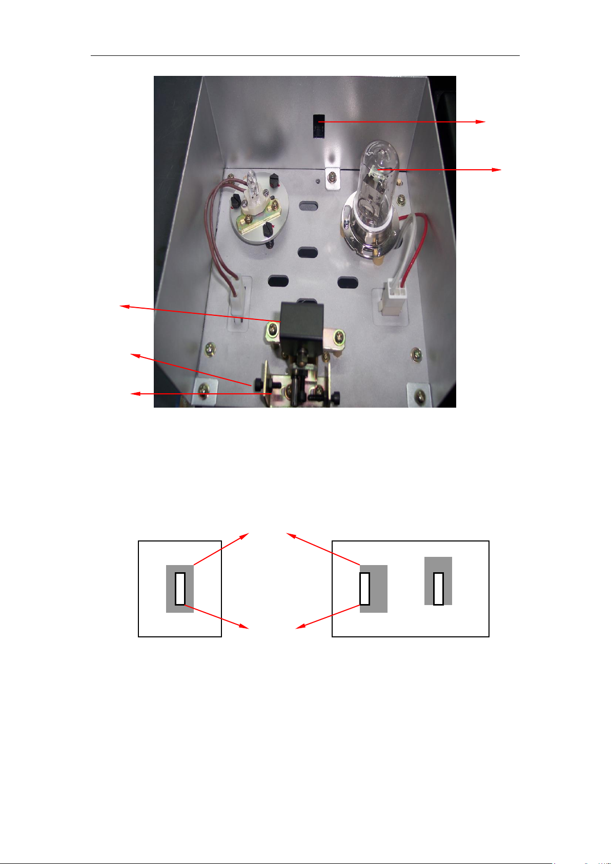
Viewfinder
Figure 4-10 Structure of light source compartment
Figure 4-11 Removing WI lamp
38

CHAPTER 4 MAINTENANCE
Bow of fuse
Twist
Figure 4-12 Install WI lamp
Figure 4-13 Shape of WI lamp fuse
39

CHAPTER 4 MAINTENANCE
Figure 4-14 Pull out/install plug of D2 lamp lead
Figure 4-15 Remove/install D2 lamp
40

CHAPTER 4 MAINTENANCE
4.4.2 Clear of Lamp Use Time
After replacing the lamp, clear the use time of old lamp. The procedures can
refer to “UV Analyst Operation Manual” relevant section.
4.4.3 Adjustment of Lamp
WARNING
Usually, after replacing lamp, there is no need to do any adjustment. If
light source adjustment is required, warnings are as follows:
(1) When lamp is ON, WI lamp and D2 lamp have high voltage. So
touching lamp and its lead is forbidden to avoid electric shock.
(2) When lamp is ON, WI lamp and D2 lamp have high temperature.
So touching surface of the lamp is forbidden to avoid scald.
(3) When D2 lamp is ON, it will emit strong ultraviolet radiation. So
avoid seeing the lamp directly.
A)The adjustment of WI lamp position are as follows: (Refer to Figure 4-16~
Figure 4-17)
(1)Turn off D2 lamp.
(2) Set wavelength below 300nm, and set 2nm slit.
Aim the viewfinder of light source at WI lamp side to make WI lamp aim at
light-entrance slit. Cofirm relative position of WI lamp facula and light-entrance
slit is OK.
If relative position of WI lamp facula and light-entrance slit has deviation, adjust
Screw C of WI lamp and Screw A of viewfinder.
If WI lamp facula has horizontal deviation, adjust screw A of viewfinder.
If WI lamp has vertical deviation, adjust Screw C of WI lamp (three in all).
After adjustment, tighten Screw A.
(3) Set wavelength as 580nm.
Open the door of sample compartment under wavelength 580nm. Insert a
white paper in front of photodiode, aiming at the shape of WI lamp facula
(yellow at 580nm). If facula is dark or the shape is abnormal, adjust Screw C of
WI lamp and Screw of viewfinder.
A, Make the shape of WI lamp facula rectangle.
◇Note: As for turning on and turning off the lamp, setting of wavelength,
please refer to relevant section.
41

CHAPTER 4 MAINTENANCE
B)The adjustment of D2 lamp position are as follows:(Refer to Figure 4-18~
Figure 4-19)
(1) Turn off WI lamp.
Confirm WI
lamp facula at
this position.
Screw C
(Three)
Viewfinder
Screw A
Nut A
WI lamp
WI lamp facula
Light-entrance slit
Normal status
Horizontal deviation
Vertical deviation
Figure 4-16 replacement and adjustment of WI lamp
Figure 4-17 Relative position of WI lamp facula and light-entrance slit
42

CHAPTER 4 MAINTENANCE
(2) Set wavelength below 300nm, and set 2nm slit.
Aim the viewfinder of light source at D2 lamp side to make D2 lamp aim at
light-entrance slit. Cofirm relative position of WI lamp facula and light-entrance
slot is OK.
If relative position of D2 lamp facula and light-entrance slit has deviation,
adjust Screw B of viewfinder.
If D2 lamp facula has horizontal deviation, adjust screw B of viewfinder.
After adjustment, tighten Screw B.
◇Note:D2 lamp is UV light source lamp. D2 lamp facula can be observed at
light-entrance slit of lamp source compartment, which is polychromatic light.
But after polychromatic light of D2 lamp has been changed into homogeneous
light by monochromator, we cannot see facula by eye. So we cannot observe
the shape of D2 lamp facula inside sample compartment by eye and we cannot
adjust D2 lamp position.
◇Note: As for turning on and turning off the lamp, wavelength settings,
transmittance/ absorbency mode setting, refer to relevant section.
◇Note: When adjusting position of WI lamp and D2 lamp, if instrument is OK
by Step (2), there is no need to perform Step (3) and Step (4).
◇Note: If position of D2 lamp and WI lamp has serious deviation, light source
viewfinder may need to be adjusted. However, the method is very complex,
please contact to Service Department for help.
43
CHAPTER 4 MAINTENANCE
Confirm D2
lamp facula at
this position.
Viewfinder
Screw
Nut B
D2 lamp assembly
D2 lamp facula
Light-entrance
Normal status
Horizontal deviation
Vertical deviation
Figure 4-18 Replacement and adjustment of D2 Lamp
Figure 4-19 Relative position of D2 lamp facula and light-entrance slit
44

CHAPTER 4 MAINTENANCE
4.5 Disassembly of Instrument Main Parts
If failures occur, parts may need to be replaced. This section mainly introduce
the disassembly methods of main parts.
WARNING
Those who has not been trained are forbidden to disassemble the
instrument, otherwise instrument may be damaged or human may be
injured.
WARNING
Pay attention to the electric shock caused by power supply voltage.
Before open the cover or disassemble the circuit of instrument, please
first turn off the power supply and pull out the power cord.
4.5.1 Open Instrument Cover
(1) Open cover of sample compartment, and unscrew the screw of cuvette
holder. Take out holder.
(2) Unscrew the screw of sample compartment holder.
(3) Loosen the screw at side of instrument.
(4) Take out instrument cover. (Do not force to the motor at front of the cover
to avoid connection line broken).
(5) Install the cover.(Do not press the connection wire of motor by cover
during installation.)
△Note
When taking out or installing the case, pay attention to avoid the sponge fallen
down.
4.5.2 Removal Procedures of Power Switch
(1) Remove instrument cover.
(2) Pull out each pin of power supply.
(3) Unscrew the screws of power supply switch and take out power supply
switch.
(4) Install the power supply switch (pay attention to plug the pins correctly).
45

CHAPTER 4 MAINTENANCE
4.5.3 Removal of Control Board and Lamp Power Supply Board
(1) Remove instrument cover.
(2) Pull out each pin of lamp power supply.
(3) Unscrew the screws of lamp power supply and take out lamp power supply.
(4) Unscrew the screw of main control board or lamp power supply board.
Take out the board.
(5) When installing them, pay attention to plug the pins correctly.
△Note
When replacing circuit board, do not bend the board forcibly.
4.5.4 Removal Procedures of Pre-amplifier
(1) Remove instrument cover.
(2) Unscrew the screw on the cover of pre-amplifier, and remove the cover of
pre-amplifier.
(3) Pull out each pin of pre-amplifier.
(4) Unscrew the screw of pre-amplifier. And take out pre-amplifier.
(5) Install pre-amplifier (pay attention to plug the pins correctly).
△Note
(1) When removing and installing reference photoelectricity convertor and
pre-amplifier, avoid touching the high-ohmic resistor by hand.
(2) Pull out and plug the signal cable with great care to avoid signal cable and
its pin broken.
46

CHAPTER 4 MAINTENANCE
4.6 Storing of Instrument
4.6.1 After Test Is Finished
(1) Turn off the instrument. Pull out the plug of power cord.
(2) Cover the instrument with dustproof cover.
△Note
If there are corrosive, volatile organic solvent or venomous sample in the
sample compartment, be sure to take them out.
4.6.2 Instrument Will Not Be Used for a Long Time
(1) Please do not place the instrument in the place with high temperature
(more than 70℃), low temperature (less than -20℃), high hunidity (more than
80%), or vibrant source.
(2) Make sure to cover the dustproof cover on the instrument.
(3) Instrument cannot be touched to corrosive and venomous gases.
(4) When instrument is being transported to storage place, fix the viewfinder by
sponge.
(5) Do not keep the instrument in electromagnetism field place.
(6) Do not keep the instrument in dusty place.
(7) Avoid direct sunlight to the instrument.
47

No. 16, 201 Minyi Road, Songjiang District, Shanghai, China
+86-21-67687200
+86-21-67687190
sh-factory@techcomp.cn
www.techcomp.cn
Shanghai Techcomp Instrument Ltd.
48
 Loading...