


15” | 19” | 22” | 26” | 32” | 42”
Instructions Manual

2
Table of Contents
Safety Guidelines 3
Package Contents 4
Ports and Connectors 5
Technical Specications 6
Installation Guidelines 7
Installation Instructions – In Wall Bracket Construction 8
Installation Instructions – In Wall Installation Method 9
Installation Instructions – On Wall Installation Method 10
Installation Instructions – In Cabinet Installation Method 11
Touch Panel Overview 12
Remote Control Overview 13
Remote Control Key Functions 14
Sky Magic Eye IR Link Instructions 15
RS-232 Protocol 16
IR Remote Control Codes 17
RJ12 Command Codes 18
IR Link In & Out Instructions 19
Smart TV User Guide 20
Smart TV Remote Control Key Functions 21
OSD Menu User Guide - 1.1 Input Source Menu 22
OSD Menu User Guide - 1.2 Menu Layout 23
Troubleshooting 24
Warranty Details 25
3
Safety Guidelines
This Kitchen Television has been rated under IP63 Waterproof Classication. The item should not be exposed
to harsh weather conditions. For safety reasons we advise that no objects are placed on top of the television
unit once installed.
Please read the following before operating this television:
• Please do not allow children to operate this television without adult supervision or guidance.
• The television should not be subjected to temperatures below 0 Celsius or above + 50 Celsius when in use.
Do not install in areas that are subjected to direct heat or light.
• Please do no carry out any maintenance or servicing on this television unless you’re a qualied technician.
• If for any reason the transformer, mains cable, remote controller or television is not performing correctly,
please contact the provider.
• Please use a qualied electrician to install the power cables to your television. If the power cable is pinched
or cut when installed, the users or installers could be subject to an electric shock.
• Disconnect the television in the event of (a) a power cut, (b) leaving the unit ON for a long period of time
unattended, and (c) for cleaning the unit.
• Do not fully submerse the television in water.
• Do not allow the television to be subjected to acid or alkaline-based substances.
• Please install the television using the provided brackets, xtures and ttings supplied by the provider.
Follow installation instructions within this manual.
• Install the television in an area that is not subjected to vibrations or within the reach of young children.
• Do not subject the television screen to hard or sharp objects at any time.
• Do not apply harmful chemicals or corrosive liquids to the television screen.
• Please remove the protective lm from the television screen and speaker panels within one week of
installing.
4
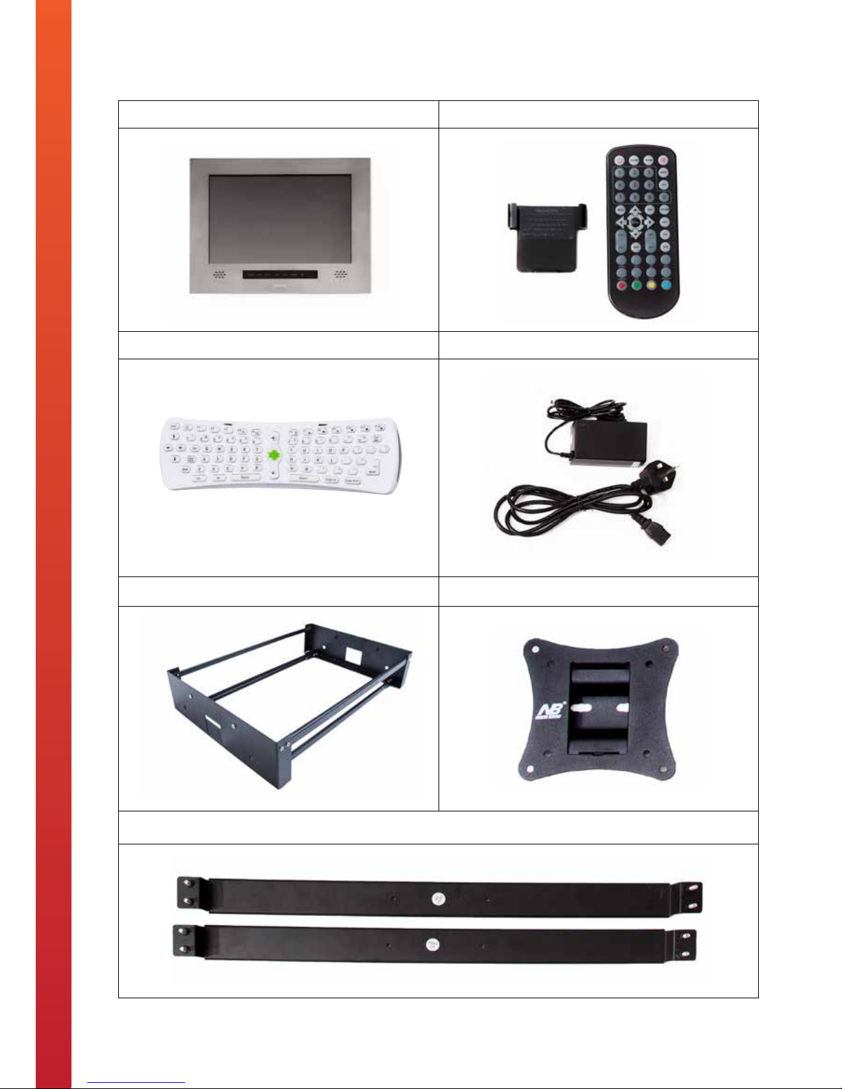
Package Contents
Kitchen Television Waterproof Remote Control and Holder
Smart TV Remote Control Power Adapter and Wired Plug
In-Wall Installation Bracket On-Wall Installation Bracket
In-Cabinet Installation Bracket
5
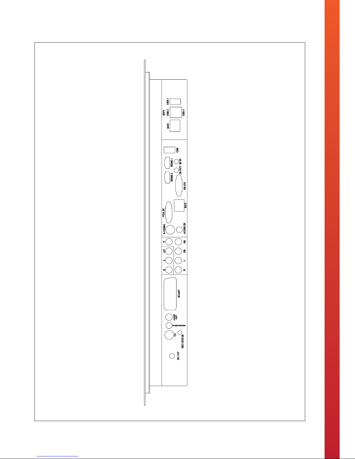
Ports and Connectors
6
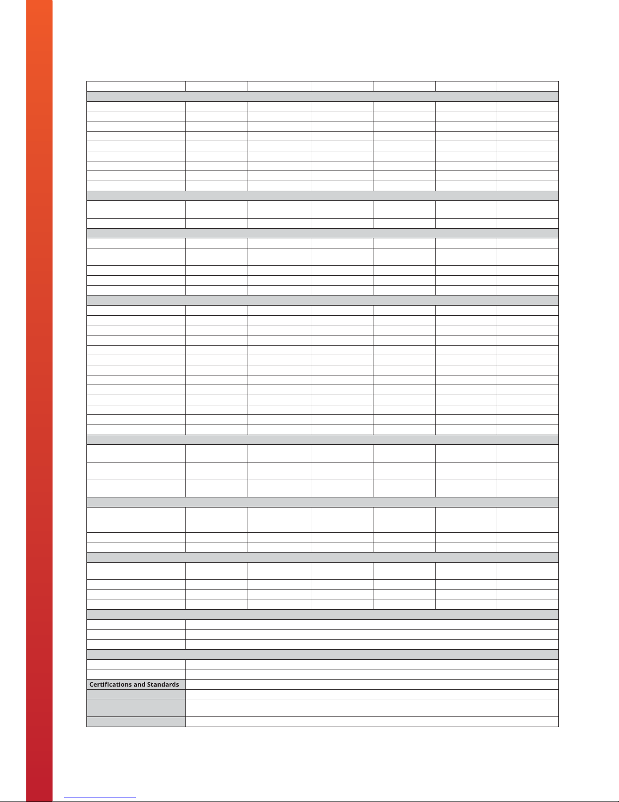
Technical Specications
Product 15” Kitchen TV 19” Kitchen TV 22” Kitchen TV 26” Kitchen TV 32” Kitchen TV 42” Kitchen TV
Display
Screen Type LED LED LED LED LED LED
Active Screen Size (W x H) 345 x 194.5 (mm) 407.5 x 254.5 (mm) 474.5 x 297 (mm) 578 x 326 (mm) 698 x 392 (mm) 933 x 526 (mm)
Resolution 1920 x 1080 pixels 1920 x 1080 pixels 1920 x 1080 pixels 1920 x 1080 pixels 1920 x 1080 pixels 1920 x 1080 pixels
Brightness 300 cd/m2 300 cd/m2 300 cd/m2 500 cd/m2 500 cd/m2 500 cd/m2
Aspect Ratio 16:9 16:9 16:9 16:9 16:9 16:9
Contrast Ratio 400:1 1000:1 1000:1 1000:1 1500:1 1500:1
Colour Depth 16.7 M 16.7 M 16.7 M 16.7 M 1.06 Billion 1.06 Billion
Viewing Angle (L / R / U / D) 89° / 89° / 89° / 89° 89° / 89° / 89° / 89° 89° / 89° / 89° / 89° 89° / 89° / 89° / 89° 89° / 89° / 89° / 89° 89° / 89° / 89° / 89°
Response Time 6 ms 6 ms 6 ms 6 ms 6 ms 6 ms
Audio
Speakers 2 x internal
speakers
2 x internal
speakers
2 x internal
speakers
2 x internal
speakers
2 x internal
speakers
2 x internal
speakers
Speaker Output 3 watts 3 watts 3 watts 5 watts 5 watts 5 watts
System
DVB-T / T2 / C TV System Yes Yes Yes Yes Yes Yes
HD Freeview (Digital) TV &
Radio
Yes Yes Yes Yes Yes Yes
Analogue Tuner Yes Yes Yes Yes Yes Yes
MHEG 5 System Yes Yes Yes Yes Yes Yes
Tech2o Smart TV Yes Yes Yes Yes Yes Yes
Ports and Connectors
TV / Aerial Input Yes Yes Yes Yes Yes Yes
Component (YPbPr) Input Yes Yes Yes Yes Yes Yes
AV Input Yes Yes Yes Yes Yes Yes
SCART Input Yes Yes Yes Yes Yes Yes
VGA Input Yes Yes Yes Yes Yes Yes
HDMI Input Yes Yes Yes Yes Yes Yes
Sky Magic Eye IR Link Yes Yes Yes Yes Yes Yes
RS 232 Input Yes Yes Yes Yes Yes Yes
RJ 12 Input Yes Yes Yes Yes Yes Yes
RJ 45 Input Yes Yes Yes Yes Yes Yes
IR IN and OUT Yes Yes Yes Yes Yes Yes
SPDIF Audio Output Yes Yes Yes Yes Yes Yes
USB Input Yes Yes Yes Yes Yes Yes
Installation
Recess Dimensions For
In-Wall Installation
(W x H x D)
475 x 310 x 100
(mm)
500 x 370 x 100
(mm)
565 x 410 100
(mm)
695 x 460 x 100
(mm)
820 x 550 x 110
(mm)
1080 x 705 x 110
(mm)
Recess Dimensions For
In-Cabinet Installation
(W X H)
465 x 295 (mm) 495 x 355 (mm) 560 x 395 (mm) 685 x 440 (mm) 810 x 535 (mm) 1070 x 685 (mm)
Wall Bracket Dimensions For
On-Wall Installation
VESA 100 x 100mm VESA 100 x 100mm VESA 100 x 100mm VESA 200 x 100mm VESA 200 x 200mm VESA 200 x 200mm
Power
Mains Power 110-240V
(DC 12V/3A
adaptor)
110-240V
(DC 12V/4A
adaptor)
110-240V
(DC 12V/4A
adaptor)
110-240V
(DC 24V/4A
adaptor)
110-240V
(DC 12V/5A
adaptor)
AC 110-240v
50/60Hz
Power Consumption 25 watts 42 watts 42 watts 50 watts 100 watts 120 watts
Standby Consumption 3 watts 3 watts 3 watts 3 watts 3 watts 3 watts
Dimensions and Weights
Unit Size 493 x 325 x 65
(mm)
516 x 385 x 65
(mm)
585 x 425 x 65
(mm)
710 x 480 x 70
(mm)
842 x 571 x 78
(mm)
1121 x 723 x 81
(mm)
Unit Weight 9 kg 13 kg 15 kg 24 kg 32 kg 42 kg
Package Size (W x H x D) 62 x 45 x 19 (cm) 63 x 51 X19 (cm) 71 x 55 x 19 (cm) 83 x 60 x 20 (cm) 95 x 68 x 18 (cm) 126 x 86 x 32 (cm)
Gross Weight 15 kg 18 kg 23 kg 36 kg 51 kg 76 kg
Design
Screen Finish Options Brushed Stainless Steel, Carbon Black and Champagne Gold
Screen Material/s 2mm Stainless Steel Sheet and 5mm Tempered Glass
Frame Material Steel Construction
Operating Environment
Working Temperature 0°C ~ +50°C
Working Humidity 10% ~ 90%
CE, RoHS, ISO9001, ISO14001
Waterproof Rating IP63
Package Contents Kitchen Television, Waterproof Remote Control and Holder, Smart TV Remote Control, Power Adapter and Wired Plug, User
Manual and Installation Guide, In-Wall Installation Bracket, On-Wall Installation Bracket and In-Cabinet Installation Bracket
Product Warranty 2 Year Warranty

7
Installation Guidelines
• We advise that a professional body should install our televisions. We do not take any liability for the
television being installed incorrectly and then causing damage or harm to the installer or user.
• Please do not open or tamper with the television, as this can break the television seal, which may lead to
water penetrating the internal parts of the television.
• The brackets provided can easily endure the weight of the television, however please conrm the area
your xing the bracket to can hold the television bracket and television weight safely.
• Install the television on a smooth surface and in an area where people are not likely to collide with the
television once installed.
• Do not plug the power cable in an area subjected to water or moisture.

8
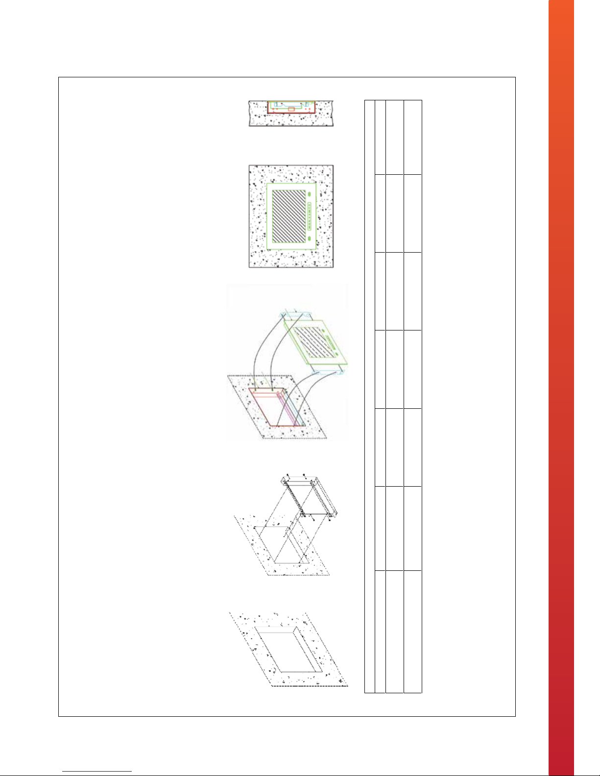
Installation Instructions – In Wall Bracket Construction
9
Installation Instructions - In Wall Installation Method
www.tech2o.tv | enquiries@tech2o.tv | +44 (0) 1509 608009
In-wall Installation Method
1. Create an opening within the chosen area of the wall. Please see the table below for specific recess dimensions that are relevant for your product.
2. Place the in-wall bracket into the recess and use the pilot holes to drill into the wall. Place the raw plugs into the holes that have been drilled and fix the bracket into position.
3. Offer the television up to the bracket that is fixed within the wall. Line up the side brackets (pre-assembled to television) with the protruding screws within the in-wall bracket and
simply push the television into situ.
Installation Data
Product 15” 19” 22” 26” 32” 42”
Unit Size
450 x 297 x 56 (mm)
536 x 360 x 62 (mm)
597.5 x 406 x 61.5 (mm) 736 x 449 x 68 (mm) 842 x 558 x 84 (mm) 1122 x 720 x 86 (mm)
Recess Dimensions (W x H x D)
430 x 280 x 90 (mm) 490 x 345 x 100 (mm) 560 x 390 x 95 (mm) 725 x 435 x 110 (mm) 810 x 545 x 125 (mm) 1105 x 705 x 110 (mm)

10
Installation Instructions - On Wall Installation Method
www.tech2o.tv | enquiries@tech2o.tv | +44 (0) 1509 608009
On-wall Installation Method
1. Attach the female section of the VESA bracket to the wall with the screws provided.
2. Attach the male section of the VESA bracket to the back of the television with the provided screws.
3. Simply offer the television up to the wall and slide the two pieces of the bracket into one another.
Installation Data
Product 15” 19” 22” 26” 32” 42”
Wall Bracket Compliance
VESA 100 x 100mm VESA 100 x 100mm VESA 100 x 100mm VESA 200 x 100mm VESA 200 x 200mm VESA 200 x 200mm
11
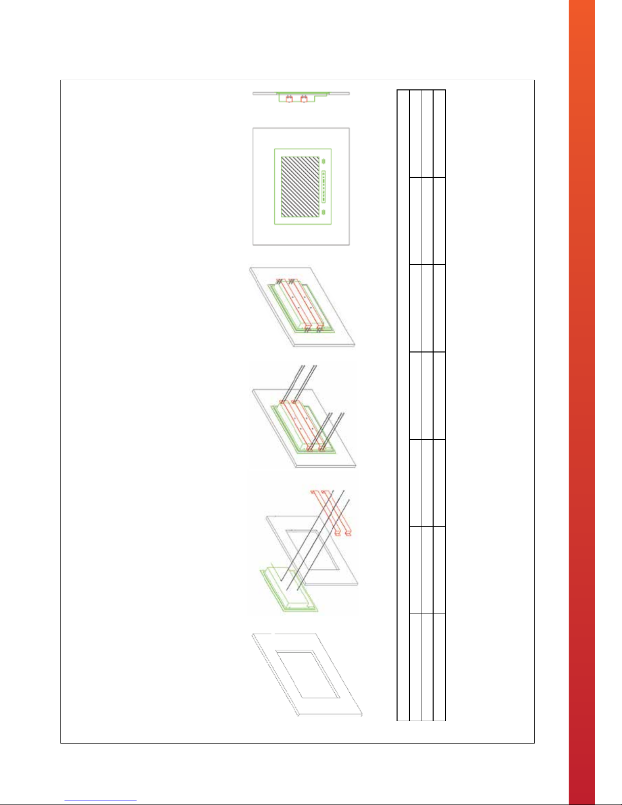
Installation Instructions – In Cabinet Installation Method
www.tech2o.tv | enquiries@tech2o.tv | +44 (0) 1509 608009
In-cabinet Installation Method
1. Create an opening within the chosen area of the cabinet. Please see the table below for specific recess dimensions that are relevant for your product.
2. Place the television into the recess and fix the fixing plate brackets onto the back of the television.
3. Turn the screws on the fixing plate bracket in a clockwise direction to clamp the television tightly and securely into position within the cabinet door.
Installation Data
Product 15” 19” 22” 26” 32” 42”
Unit Size 493 x 325 x 65 (mm) 516 x 385 x 65 (mm) 585 x 425 x 65 (mm) 710 x 480 x 70 (mm) 842 x 571 x 78 (mm) 1121 x 723 x 81 (mm)
Recess Dimensions (W x H) 465 x 295 (mm) 495 x 355 (mm) 560 x 395 (mm) 685 x 440 (mm) 810 x 535 (mm) 1070 x 685 (mm)

12
Touch Panel Overview
Button Action
MENU This button allows the user to view or exit the On-Screen Menu
Display.
Volume (Decrease) This button allows the user to turn down the volume.
Volume (Increase) This button allows the user to turn up the volume.
Channel (-) This button allows the user to move down the channel list, as
well as move down the On-Screen Menu Display.
Channel (+) This button allows the user to move up the channel list, as well
as move up the On-Screen Menu Display.
SOURCE This button allows the user to switch input source.
Power You can turn the television to Stand-By or to turn the television
ON using this button.

13
Remote Control Overview
• The waterproof remote controller comes with one CR2025 3V battery ready installed.
• The remote controller doesn’t need syncing to the television.
• To control the television with the remote controller, simply aim the controller at the television. If there are
barriers between the remote controller and television the response may be delayed or non-existent.
• For the best remote controller connection stay within 3-metres of the television and keep the remote at a
30-degree angle. The remote controller will stay connected to the television up to a distance of 8 meters.
• The remote controller is rated IPX5 waterproof classication. Do not submerse the remote controller
underwater for long periods of time.
• To change the batteries use a coin to rotate the opening on the back of the remote controller.

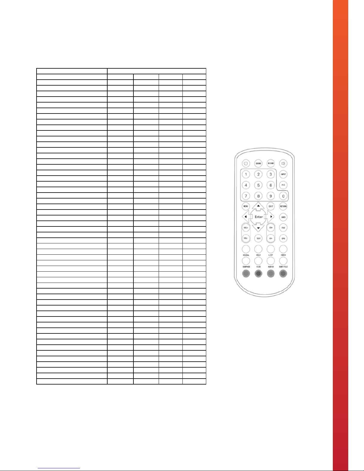
14
Remote Control Key Functions
TV Remote Control Key Functions
Button Function
POWER ON / Stand-By
SOUND Switch to Sound Mode
NICAM Enter or Exit the On-Screen DTV Menu within
DTV
MUTE Sound ON / OFF - The screen will display a
MUTE logo when the sound is OFF
0-9 Manual Channel Selection
INPUT Change Source Mode
PIC Switch to Picture Mode
MENU Enter or Exit the On-Screen Menu
Up / Down selector for the On-Screen Menu
Left / Right selector for the On-Screen Menu
ENTER
EXIT Exit the On-Screen Menu
RETURN Return to Previous Channel
INFO Display the channel name or any other
signal source
VOL+ Increase the volume
VOL- Decrease the volume
CH+ Move up a channel
CH- Move down a channel
FAV Display your favorite channel list
EPG Run the electronic program guide list within
DTV
TEXT Open Teletext
REVEAL Reveal Hidden Text in Teletext
HOLD Hold a page in Teletext
LIST Enter List Mode in Teletext
INDEX Enter Index Mode in Teletext
SUBPAGE Reveal Subpage in Teletext
SIZE Switch aspect ratio of the displayed picture
AUDIO Enter Audio Mode in Teletext
SUBTITLE Language Selection
COLOURED
BUTTONS
Teletext Selector
/
/
15
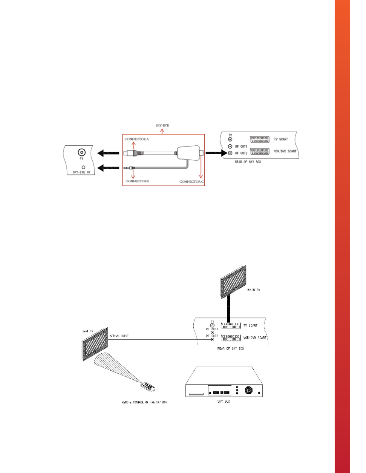
The external Sky Magic Eye IR Link allows you to control Sky Digital broadcasts on your Television…
Enabling you to view Sky television programmes and control the Sky box from another location.
To setup the Sky Magic Eye IR Link, you will need to run a length of coax cable from the socket marked RF2
output on the back of the Sky box directly to the Sky Magic Eye IR Link aerial input (labelled as Connector C on
the diagram below). Then attach the Sky Magic Eye IR Link to the TV by connecting Aerial (Connector A) with the
televisions aerial input, and IR (Connector B) with the televisions Sky Eye IR input. Please refer to the diagram
below for illustrative reference of how to set up your Sky Magic Eye IR Link System:
Sky television programmes can then be viewed on the ANALOGUE part of the tuner. Your Sky box needs to be
set up to faciliate for an RF2 output. Please refer to your Sky user guide on how to do this.
Control of the Sky system is available via either a standard Sky remote control or the included learning remote
control. The IR receiver within the television will receive the IR signal from the remote control, send it back
down the aerial cable to the Sky box allowing you to have complete control from another location.
Sky Magic Eye IR Link Instructions
Sky Magic Eye IR Link
Sky Magic Eye IR Link
The external Sky Magic Eye IR Link allows you to control Sky Digital broadcasts on your Television… Enabling you to
view Sky television programmes and control the Sky box from another location.
To setup the Sky Magic Eye IR Link, you will need to run a length of coax cable from the socket marked RF2 output on the back of the
Sky box directly to the Sky Magic Eye IR Link aerial input (labelled as Connector C on the diagram below). Then attach the Sky Magic
Eye IR Link to the TV by connecting Aerial (Connector A) with the televisions aerial input, and IR (Connector B) with the televisions Sky
Eye IR input. Please refer to the diagram below for illustrative reference of how to set up your Sky Magic Eye IR Link System:
6 SKY-EYE instructions tech2o kitchen.pdf 1 12/08/2013 19:54
16
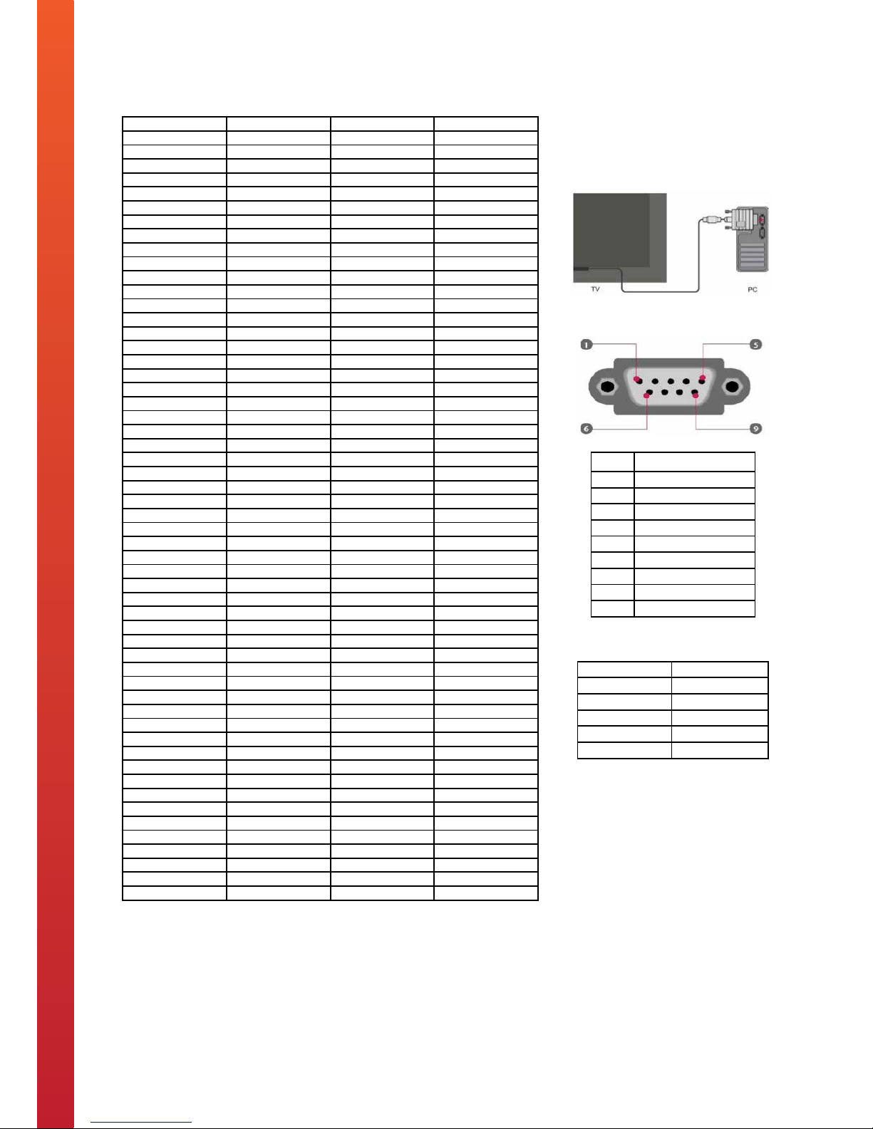
RS-232 Protocol
RS-232 Protocol
Pin Function
1 Data Carrier Data
2 Receiver Data
3 Transmit Data
4 Data Terminal Ready
5 Signal Ground
6 Data Set Ready
7 Request To Send
8 Clear To Send
9 Ring Indicator
This RS-232 input connector allows the
Television to receive command codes
from Home Automation Systems.
Connection
RS-232 Port Pin Configuration
Communication Settings
Command Code Sequence
A0 F0 55 FF <IR Code> <CH Code>
The time of the command sequence must be
<500 ms.
The interval time of two continuous command
sequences must be >500 ms.
Port COM
Code Hex form
Baud Rate 38400 bps
Data length 8 bits
Parity Bit None
Stop Bit 1 bit
Function IR Code CH Code RS-232 Code
POWER ON 2C D4 A0F055FF2CD4
POWER OFF 2E D2 A0F055FF2ED2
SOUND 4A B6 A0F055FF4AB6
NICAM 14 EC A0F055FF14EC
MUTE 08 F8 A0F055FF08F8
1 54 AC A0F055FF54AC
2 16 EA A0F055FF16EA
3 15 EB A0F055FF15EB
4 50 B0 A0F055FF50B0
5 12 EE A0F055FF12EE
6 11 EF A0F055FF11EF
7 4C B4 A0F055FF4CB4
8 0E F2 A0F055FF0EF2
9 0D F3 A0F055FF0DF3
0 0C F4 A0F055FF0CF4
INPUT 17 E9 A0F055FF17E9
PIC 4E B2 A0F055FF4EB2
MENU 18 E8 A0F055FF18E8
UP 1A E6 A0F055FF1AE6
RIGHT 07 F9 A0F055FF07F9
LEFT 47 B9 A0F055FF47B9
DOWN 48 B8 A0F055FF48B8
ENTER 06 FA A0F055FF06FA
EXIT 0A F6 A0F055FF0AF6
RETURN 49 B7 A0F055FF49B7
INFO 5C A4 A0F055FF5CA4
VOL+ 4B B5 A0F055FF4BB5
VOL- 4F B1 A0F055FF4FB1
CH+ 09 F7 A0F055FF09F7
CH- 05 FB A0F055FF05FB
FAV 58 A8 A0F055FF58A8
TEXT 03 FD A0F055FF03FD
EPG 40 C0 A0F055FF40C0
REVEAL 5E A2 A0F055FF5EA2
LIST 52 AE A0F055FF52AE
HOLD 5A A6 A0F055FF5AA6
INDEX 56 AA A0F055FF56AA
SUBPAGE 5F A1 A0F055FF5FA1
SIZE 5B A5 A0F055FF5BA5
AUDIO 53 AD A0F055FF53AD
SUBTITLE 57 A9 A0F055FF57A9
RED 5D A3 A0F055FF5DA3
GREEN 59 A7 A0F055FF59A7
YELLOW 51 AF A0F055FF51AF
BLUE 55 AB A0F055FF55AB
DTV 21 DF A0F055FF21DF
ATV 26 DA A0F055FF26DA
COMPONENT 2F D1 A0F055FF2FD1
PC-RGB 61 9F A0F055FF619F
HDMI1 64 9C A0F055FF649C
HDMI2 6D 93 A0F055FF6D93
HDMI3 (Internet) 6E 92 A0F055FF6E92
SCART 6F 91 A0F055FF6F91
S-VIDEO 45 BB A0F055FF45BB
AV1 42 BE A0F055FF42BE
Pin Function
1 Data Carrier Data
2 Receiver Data
3 Transmit Data
4 Data Terminal Ready
5 Signal Ground
6 Data Set Ready
7 Request To Send
8 Clear To Send
9 Ring Indicator
This RS-232 input connector allows the
Television to receive command codes
from Home Automation Systems.
Connection
RS-232 Port Pin Configuration
Communication Settings
Command Code Sequence
A0 F0 55 FF <IR Code> <CH Code>
The time of the command sequence must be
<500 ms.
The interval time of two continuous command
sequences must be >500 ms.
Port COM
Code Hex form
Baud Rate 38400 bps
Data length 8 bits
Parity Bit None
Stop Bit 1 bit
17
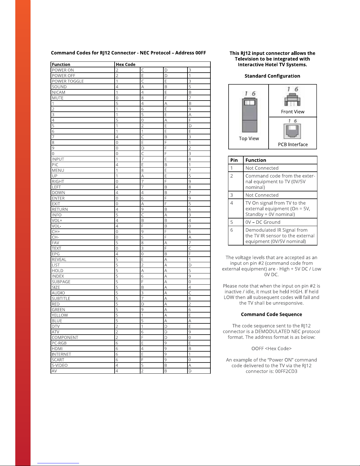
IR Remote Control Codes
IR Remote Control Codes
These Codes can be used to program
an IR Remote Control to transmit an
IR Signal to operate the Television.
Command Code Sequence
The code sequence is a DEMODU-
LATED NEC protocol format. The
address format is as below:
OOFF <Hex Code>
An example of the “Power ON”
command code delivered to the TV via
the IR Remote Control is: 00FF2CD3
To program an IR Remote Control to transmit an IR Signal to operate
the Television, please refer to the codes (NEC Protocol – Address
00FF) in the table below:
Function Hex Code
POWER ON 2 C D 3
POWER OFF 2 E D 1
POWER TOGGLE 1 C E 3
SOUND 4 A B 5
NICAM 1 4 E B
MUTE 0 8 F 7
1 5 4 A B
2 1 6 E 9
3 1 5 E A
4 5 0 A F
5 1 2 E D
6 1 1 E E
7 4 C B 3
8 0 E F 1
9 0 D F 2
0 0 C F 3
INPUT 1 7 E 8
PIC 4 E B 1
MENU 1 8 E 7
UP 1 A E 5
RIGHT 0 7 F 9
LEFT 4 7 B 8
DOWN 4 4 B 7
ENTER 0 6 F 9
EXIT 0 A F 5
RETURN 4 9 B 6
INFO 5 C A 3
VOL+ 4 B B 4
VOL- 4 F B 0
CH+ 0 9 F 6
CH- 0 5 F A
FAV 5 8 A 7
TEXT 0 3 F C
EPG 4 0 B F
REVEAL 5 E A 1
LIST 5 2 A D
HOLD 5 A A 5
INDEX 5 6 A 9
SUBPAGE 5 F A 0
SIZE 5 B A 4
AUDIO 5 3 A C
SUBTITLE 5 7 A 8
RED 5 D A 2
GREEN 5 9 A 6
YELLOW 5 1 A E
BLUE 5 5 A A
DTV 2 1 D E
ATV 2 6 D 9
COMPONENT 2 F D 0
PC-RGB 6 E 9 E
HDMI 6 4 9 B
INTERNET 6 E 9 1
SCART 6 F 9 0
S-VIDEO 4 5 B A
AV 4 2 B D
9 IR Remote Control Codes tech2o kitchen.pdf 1 12/08/2013 20:25
These Codes can be used to program
an IR Remote Control to transmit an
IR Signal to operate the Television.
Command Code Sequence
The code sequence is a DEMODU-
LATED NEC protocol format. The
address format is as below:
OOFF <Hex Code>
An example of the “Power ON”
command code delivered to the TV via
the IR Remote Control is: 00FF2CD3
18
RJ12 Command Codes
8 RJ12 Connection Instructions tech2o kitchen.pdf 1 14/08/2013 19:06

19
IR Link In & Out Instructions
IR Link In & Out
IR Links enable control of external equipment via the IR sensor on the Television, and control of the
Television from a remote location.
IR Link IN
The IR Link IN is a 3.5mm stereo jack socket. This
socket allows an auxiliary IR sensor receiver
(included) to be connected to the Television to
enable remote control of the Television from a
different point other than the front of the
Television.
IR Link OUT
The IR Link OUT is a 3.5mm mono jack socket. The
IR signal sensed by the Television is outputted from
this socket to an IR emitter (included). This will
enable the remote control of external equipment,
such as a DVD player from the Television itself.
10 IR Link In & Out Instructions tech2o kitchen.pdf 1 12/08/2013 20:28
20
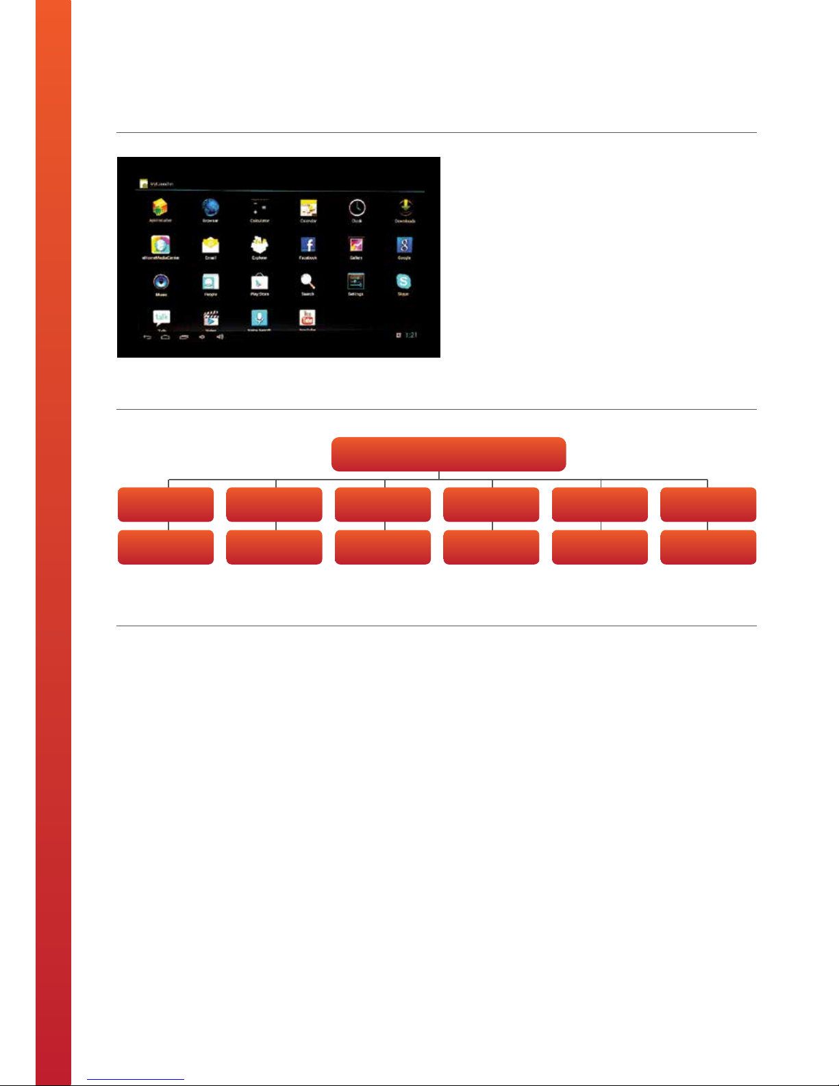
Smart-TV User Guide
Smart TV User Guide
1.0 Specification
2.0 Menu Layout
• Built on a Linux-based Android operating system
developed by Google
• Equipped with Wi-Fi and Ethernet input for internet
connectivity
• Google Play Application installed as standard allowing
you to access and download a multitude of android
applications
• Supports USB input and Media Player for presentation
of media (picture, video and audio) in a wide range of
formats
• Supports wireless keyboard and mouse
• Supports multiple languages
3.0 Network Setup Instructions
Wi-Fi Connectivity
a. Select "Settings" on the Smart TV homepage menu
b. Set Wi-Fi to be "ON" and the system will automatically
scan for available wireless networks
c. Once the scanning process has finished, the available
networks will be listed on the screen
d. Select the wireless network to connect with, and if
secure, enter the relevant password
Note: when in Wi-Fi mode, the signal status indicator will be
displayed in the status bar at the top of the page, which
describes the current strength of signal.
LAN Connectivity
a. Select "Settings" on the Smart TV homepage menu
b. Set Ethernet to be "ON"
c. If your network allows for dynamic acquisition of IP
address, then the system will automatically acquire the
IP address for you. If your network does not allow
dynamic acquisition of IP address, then you will have to
select "Static IP Settings" and input the relevant
information accordingly.
Smart TV Menu Interface
Applications Internet Music Video Picture Settings
Access &
download apps
Browse the
net
Play audio
files (USB)
Play video
files (USB)
Play picture
files (USB)
Change system
settings
11 Smart-TV User Guide tech2o kitchen.pdf 1 12/08/2013 20:30
21
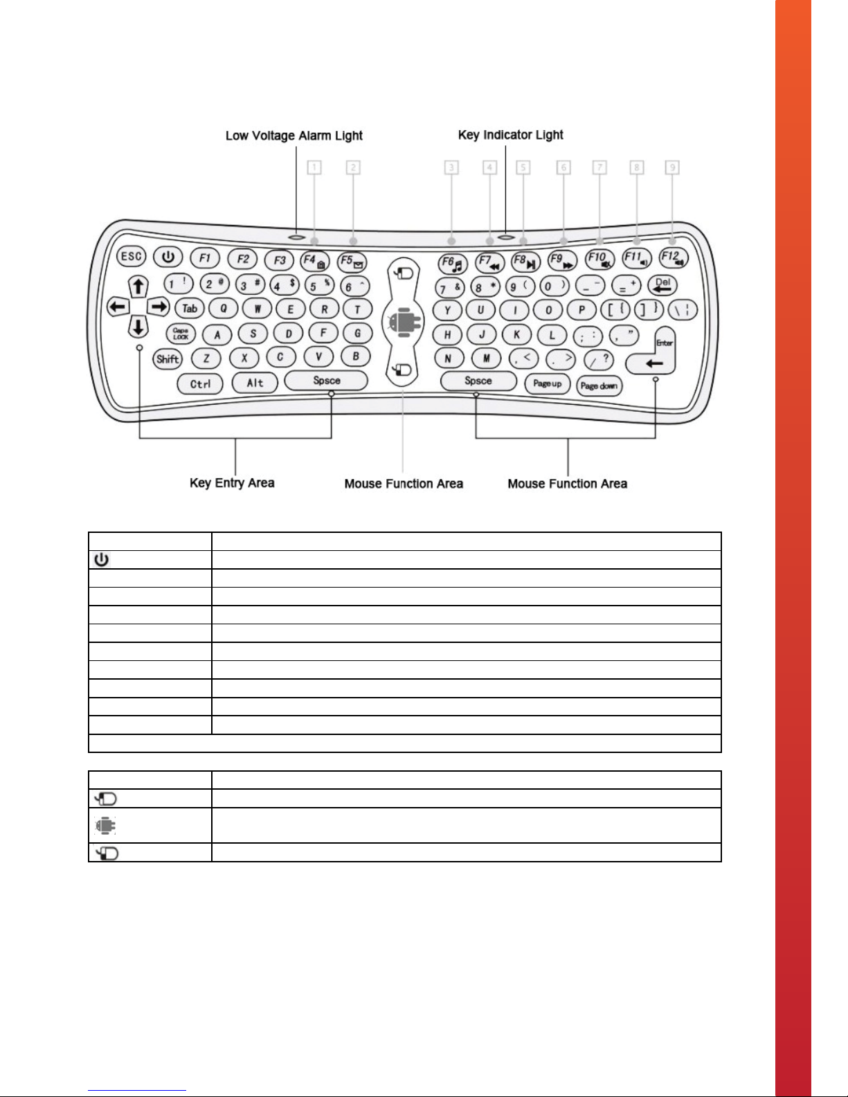
Smart TV Remote Control Key Functions
Smart TV Remote Control Key Functions
Button Function
Power ON / Stand by
[F4] Open the system default home page within the web browser
[F5] Open the system default email client
[F6] Open the system default media player
[F7] Play previous media
[F8] Play or Pause media
[F9] Play next media
[F10] Sound ON / OFF - The screen will display a MUTE logo when the sound is OFF.
[F11] Decrease the volume
[F12] Increase the volume
Note: Other key functions are the same as those of a standard keyboard.
Mouse Function
Right button of the mouse
Cursor key. Hold down this key and the cursor will move with the movement of the remote
control. Release the key and the cursor position will be locked.
Left button of the mouse
3 Smart TV Remote Control Key Functions tech2o Kitchen.pdf 1 12/08/2013 20:31
22
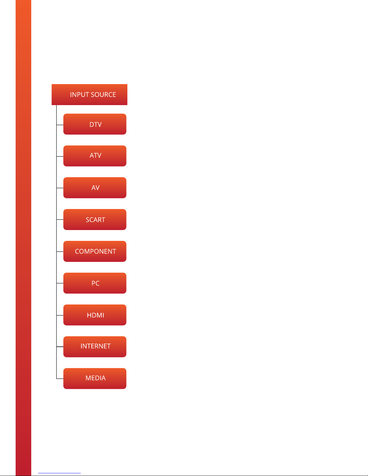
OSD Menu User Guide - 1.1 Input Source Menu
Press the TV/AV button to display the input source menu.
Press ▼ / ▲ to select the input source you want to select.
Press the OK button to enter the input source.
Press the EXIT button to quit.

23
OSD Menu User Guide - 1.2 Menu Layout
A. Menu Screenshot
B. Menu Layout

24
Troubleshooting
If you are experiencing problems with your television please read through all the troubleshooting points below
before contacting the provider.
Problem Subjects Possible Solutions
No Power
• Check that there is a green light on the mains power cable – transformer. If
the green light isn’t ON then please check the connections.
• Unplug the television from the mains for 5 minutes and check all
connections. Plug the television in to mains and try again.
No Television Signal
• Check whether the aerial that’s connected to the television is getting a
reception.
• Check that the Coax cable has been plugged in to the television correctly.
• Check that all other ports are working properly, including SCART, HDMI &
USB.
Poor Picture Quality
• Check or adjust the following screen settings: Contrast Ratio, Colour, Tint and
Brightness.
• Try returning the television settings back to factory settings or running the
Auto Picture Function.
No Sound
• Check that the MUTE function is not switched On.
• Check that the audio inputs are connected correctly.
• Increase the television volume.
• Use the remote controller to reprogram the sound settings within the
television’s Main Menu.
Picture Shadow
• This may be down to the quality of signal being received via the aerial
antenna. Please consult an aerial specialist to run checks.
No Remote Controller
Response
• Change the batteries within the remote control.
• The remote controller will only work within 8 meters of the television.
If you are experiencing a fault that is not listed above then please contact the provider.

25
Warranty Details
• All Tech2o televisions are guaranteed to be free from defects in parts and manufacture for 2 years from
the date of purchase, provided that the product is used under the normal operating conditions stated
within the manual.
• The warranty is only available to the original purchaser and is not transferable. Your consumer rights are
not aected.
• If there are any defects with your television please contact the provider stating your invoice number, date
of purchase, full name and address.
• Do not attempt to repair or take apart the television your self. If the television has been tampered with
before it arrives with us, the warranty will be void.
• We advise that all customers retain original packaging should the unit need to be returned.
• If your television occurs a problem outside of the warranty period, we oer a repair service where we can
collect and professionally repair your television.

26
Notes

27
Notes

www.tech2o.tv | enquiries@tech2o.tv | +44 (0) 1509 608006
 Loading...