

Page 1
POWER REQUIREMENTS
Utilizes included 9V DC, 100-240V universal auto-switching power
supply, 200mA minimum, center negative.
NOTE: See page 7 for instructions how to change the prong
assembly for countries other than the US.
Tech 21 Model #DC9.
For replacements, contact your local dealer/distributor, or Tech 21.
Maximum power consumption of the Fly Rig: approx 150mA.
ARNINGS:
W
* There are no user-serviceable parts inside. Attempting to repair unit is
not recommended and may void warranty.
* Missing or altered serial numbers automatically void warranty. For
your own protection: be sure serial number labels on the unit’s back
plate and exterior box are intact, and return your warranty
registration card or register online.
Note: This equipment has been tested and found to
comply with the limits for a Class B digital device, pursuant
to part 15 of the FCC Rules. These limits are designed to
provide reasonable protection against harmful interference
in a residential installation. This equipment generates, uses and can radiate radio frequency energy and, if not installed and used in accordance
with the instructions, may cause harmful interference to radio communications. However, there is no guarantee that interference will not
occur in a particular installation. If this equipment does cause harmful
interference to radio or television reception, which can be determined
by turning the equipment off and on, the user is encouraged to try to
correct the interference by one or more of the following measures:
• Reorient or relocate the receiving antenna.
• Increase the separation between the equipment and receiver.
• Connect the equipment into an outlet on a circuit different from that
to which the receiver is connected.
• Consult the dealer or an experienced radio/TV technician for help.
WARRANTY:
ONE YEAR LIMITED. PROOF OF PURCHASE REQUIRED.
Manufacturer warrants unit to be free from defects in materials and
workmanship for one (1) year from date of purchase to the original
purchaser and is not transferable. This warranty does not include damage resulting from accident, misuse, abuse, alteration, or incorrect current or voltage. If unit becomes defective within warranty period, Tech
21 will repair or replace it free of charge. After expiration, Tech 21 will
repair defective unit for a fee.
REPAIRS:
ALL REPAIRS for residents of U.S. and Canada: Call Tech 21 for
Return Authorization Number. Manufacturer will not accept
packages without prior authorization, pre-paid freight (UPS preferred)
and proper insurance. International residents should contact our local
distributor, which can be found on the Support page of our website.
FOR PERSONAL ASSISTANCE & SERVICE:
Contact Tech 21 weekdays 10:00 AM to 5:00 PM, EST: 973-777-6996.
Hand-built in the U.S.A. using high-quality components
sourced domestically and around the globe.
T: 973-777-6996 • F: 973-777-9899
E: info@tech21nyc.com • W: tech21nyc.co m
©2019 Tech 21 USA, Inc. (rev 9 /19 )
Page 2
TECH 21, THE COMPANY
Tech 21 was formed by a guitarist possessing the unusual combination
of a trained ear and electronics expertise. In 1989, B. Andrew Barta
made his invention commercially available to players and studios around
the world. His highly-acclaimed SansAmp™ pioneered Tube Amplifier
mulation in professional applications for recording direct and perform-
E
ing live, and created an entirely new category of signal processing. There
have since been many entries into this niche, yet SansAmp continues to
maintain its reputation as the industry standard.
With a full line of SansAmp models, Tech 21 also offers effect pedals
and MIDI products, as well as “traditional” style amplifiers for guitar and
bass. Each product is thoughtfully and respectfully designed by B. Andrew Barta himself with the player in mind. Our goal is to provide you
with flexible, versatile tools to cultivate, control, refine and redefine
your own individual sound. Tech 21 takes great pride in delivering consistent quality sound, studio to studio, club to club, arena to arena.
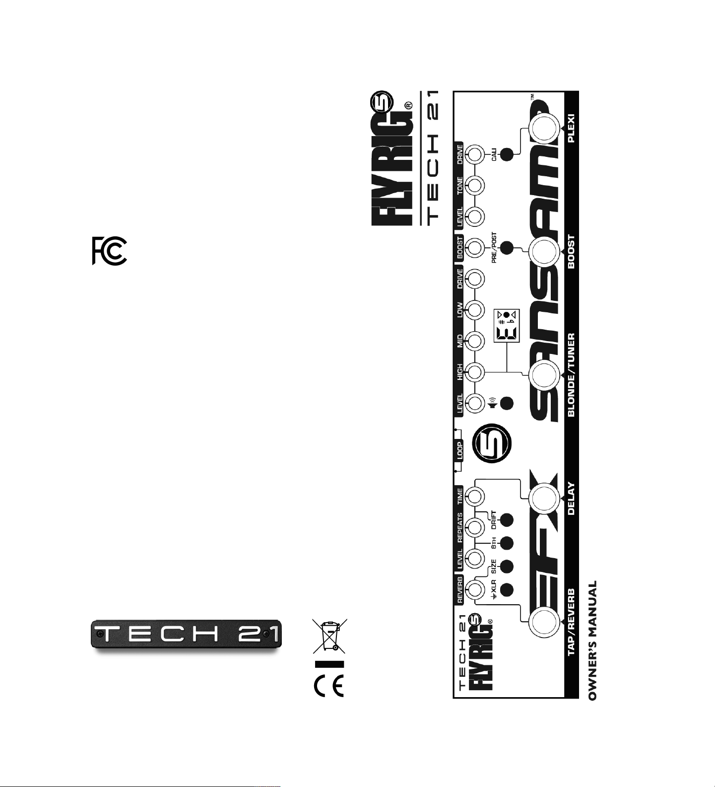
PRODUCT OVERVIEW
Each Tech 21 Fly Rig is much more than a pedalboard. In a single pedal.
And no board. Less than 13 inches long and weighing just over 20 oz.,
each sleek, compact unit embodies an entire rig. At the heart, is the allanalog SansAmp, which makes it possible to go direct to a PA or mixer.
For effects, you have the essentials and the ability to add some fun stuff,
too. What you don’t have are crackling patch cables, dying batteries or
ground loops. No stinkin’ van, heavy flight cases, cable spaghetti, and no
dead weight.
With a Tech 21 Fly Rig, you can relax. For fly gigs across the globe, jamming at the local hang, and last minute sessions, you’ll be the first one
ready to go. You can stop stressing over what to pack and agonizing over
what to leave behind. You can stop dreading cheesy backline loaners and
overheating at the mere thought of your touring rig going down. Just
pop your Fly Rig into your guitar case or backpack and head for the
door. (Be sure to wipe that smile off your face when the rest of the band
shows up sweating and out of breath.)
APPLICATIONS
As a PRE-AMP or STOMPBOX with a guitar amp.You can
connect the Fly Rig 5 in-line just as you would a standard distortion
pedal. If the pre-amp of your amplifier is imparting too much of its own
character on the pedal, plug into the low level input and set the preamp as clean and neutral as possible. As most amps tend to be on the
bright side, you may need to start with High in the Blonde SansAmp
section below 12 o’clock and adjust as necessary.
Also, be aware that most tube amps have a tone stack. When everything is on max, they tend to cut the mid-range. So don’t be surprised
to find that the flattest sound is achieved with bass and treble at minimum, and mid at max. Since most tube amp passive tone stacks work in
a similar fashion, we recommend this as a good starting point and adjusting to taste.
You can also plug into the effects loop return of your amplifier (if the
amp has one). This will disable the entire pre-amp of the amp for a
truer representation of the pedal’s sound.
For DIRECT RECORDING or DIRECT to PA. All of the tone
shaping and cabinet emulation needed is already incorporated into the
SansAmp sections of the pedal. It can be plugged into mixers (live and
studio), workstation/recorders, and even directly into the sound card
on a computer.
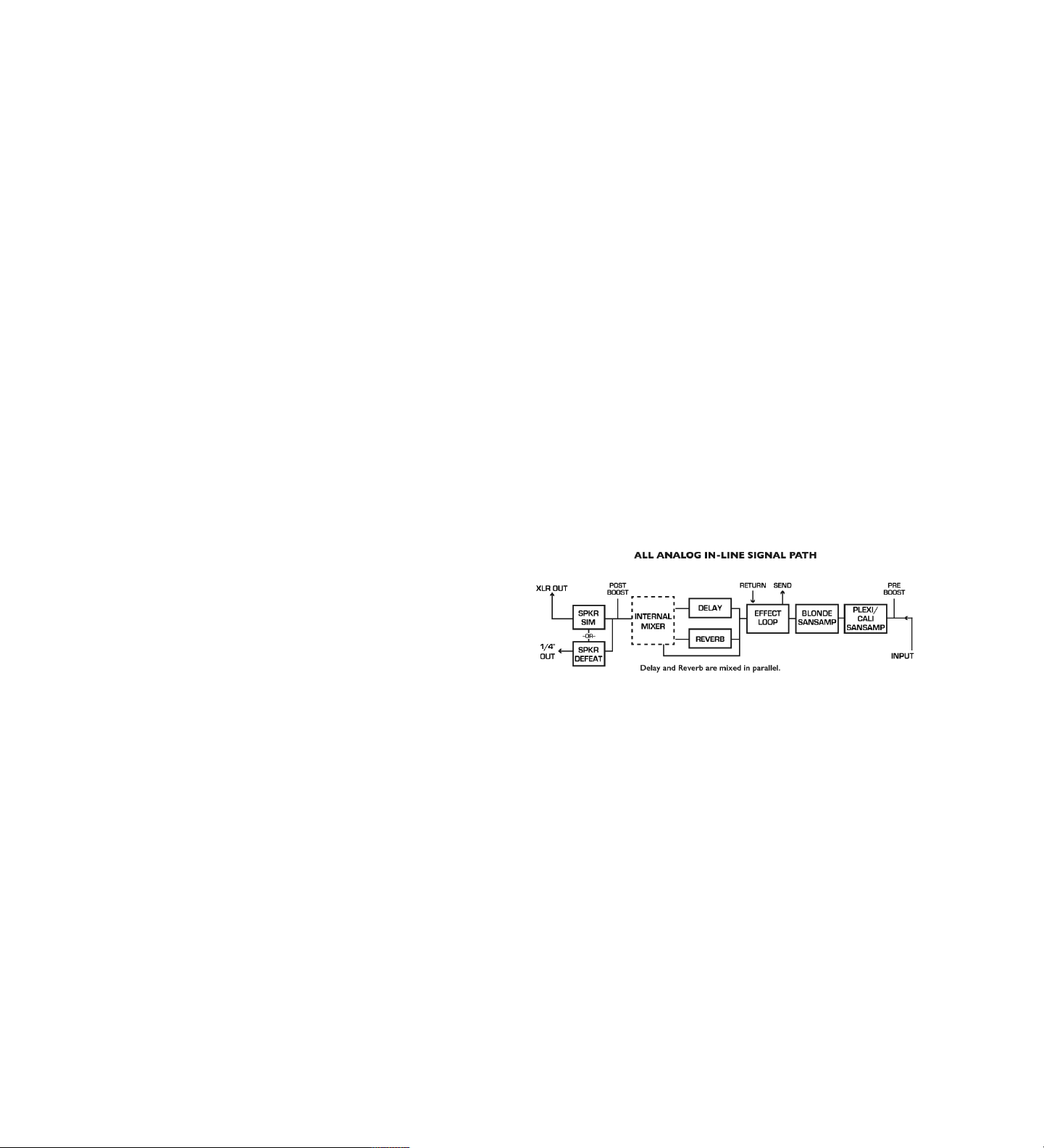
GOOD TO KNOW BEFORE YOU START
SIGNAL FLOWS RIGHT TO LEFT
FLY RIG 5 v2
The original Fly Rig, introduced in 2014, was a true game-changer for
players in all categories, from touring pros to bedroom hobbyists. At a
time when pedalboards were expanding and backs were breaking, the
innovative Fly Rig enabled players to slim down without sacrificing great
tone, and travel without fear of baggage surcharges and dreaded mystery backlines.
Going beyond being just a multi-effects unit, the all-analog SansAmp™
technology enables any Tech 21 Fly Rig to be an actual “rig.” You can run
directly into mixers of recording desks and PA systems, as well as augment your existing amplifier set-up. Always seeking to improve our
offerings and listening to customer feedback, we’ve incorporated some
new features to follow the same form factor as later Fly Rigs, such as
the Bass, Acoustic, and Paul Landers Signature PL1.
The Fly Rig 5 v2 retains the same SansAmp heart, but adds a few twists
and turns. New features include an independent reverb with choice of
room size, switchable pre/post Boost, an effect loop, a tuner, and an
XLR Output.
1
2
Page 3
THE INS AND OUTS
1/4” INPUT: 1megOhm instrument level. For normal operation, sig-
al level to Input should be close to that of a standard electric guitar
n
(approx -10dBm / 250mV). The input is designed with the same sensitivity and loading characteristic as a tube amp.
GUIDE TO FUNCTIONS and CONTROLS
SANSAMP Sections
he SansAmp technology enables the Fly Rig 5 to run directly into mixers
T
f recording desks and PA systems, as well as augment your existing am-
o
lifier set-up. It can also be used to enhance previously recorded tracks.
p
!! WARNING !! DO NOT RUN THE SPEAKER OUT-
PUT OF ANY AMP directly into a Fly Rig/SansAmp
input. Severe damage will result.
1/4” UNIVERSAL OUTPUT: Unbalanced 1kOhm Low Z instru-
ment level output. This output can be connected to High Z guitar amplifiers (or effects) as well as Low Z mixer and computer inputs. Output level
is unity gain when pedal is in bypass mode. It also drives long cables without
loss of signal integrity, even in bypass.
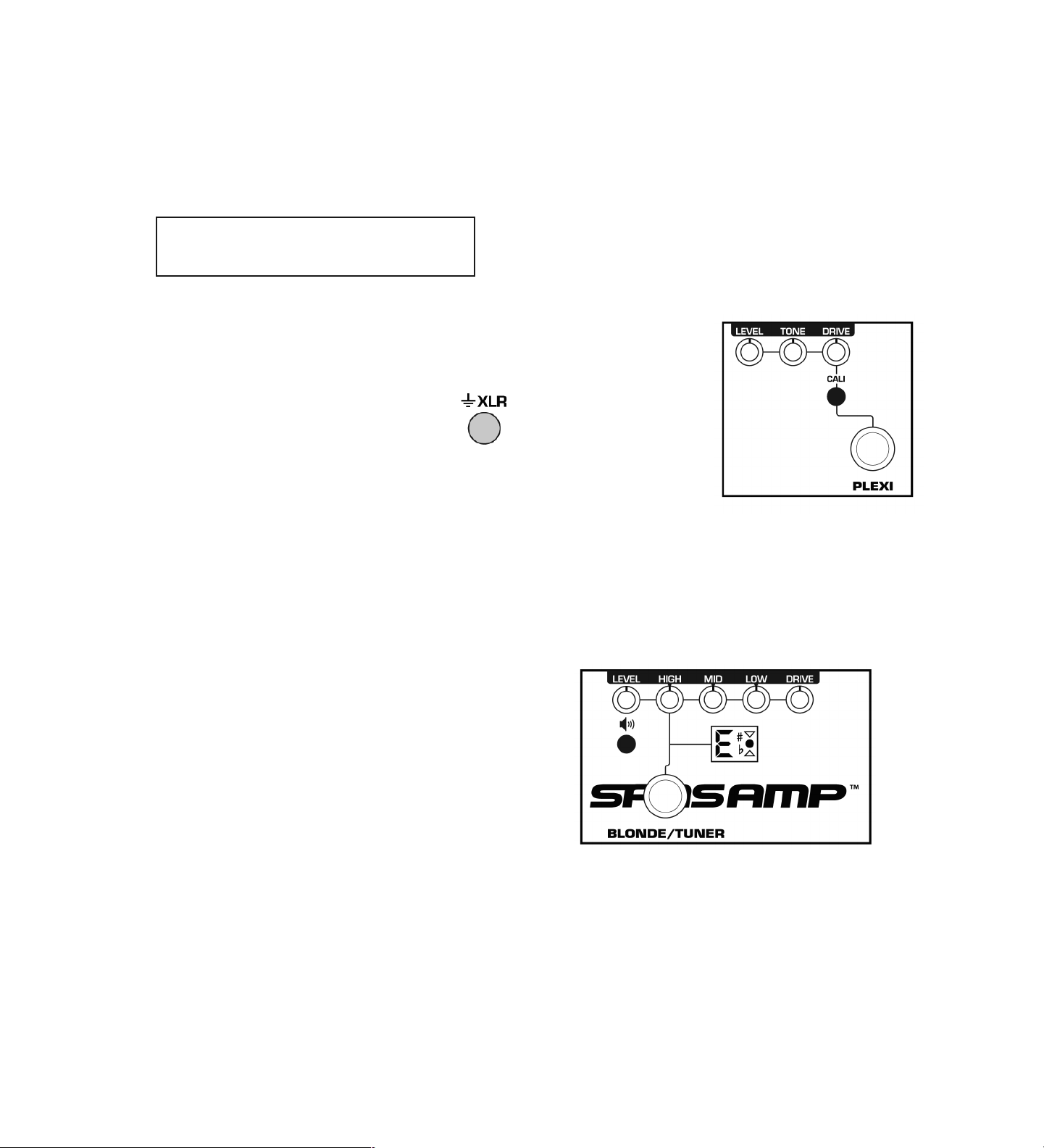
BALANCED XLR OUTPUT & GROUND
CONNECT SWITCH: Balanced low Z output. When the
Ground Connect switch is engaged, the ground connects.
Disengaged, the ground of your stage system and other interconnected gear is lifted (isolated) from the ground of the
mixing console.
NOTE: Both outputs can be used simultaneously. For example, 1/4"
Out to your amp and XLR Out to PA mixer, which is one instance
where the Ground might need to be disengaged.
LEVEL CONTROLS
SET LEVEL CONTROLS FOR UNITY GAIN
Set the level controls so you have the same volume coming from your
speaker/monitor whether the pedal is active or in bypass. This ensures
the next device in the signal chain won't get slammed by a much hotter
signal than what would normally come from the instrument. Similarly,
you wouldn't want a drop in volume either, which would force the next
device to struggle for enough signal.
PLEXI/CALI SansAmp Section
rovides the dirtier side of the Fly Rig. You have a choice of a roaring
P
lexi tone with its muscular crunch, detailed mids and mule-kick low
P
nd or you can engage the Cali switch (in position) for the chunk of a
e
70s high gain amp tone inspired by the then-boutique shop over on the
‘
est Coast. Each mode can be dialed in to your liking with dedicated
W
rive, Tone and Level controls.
D
DRIVE: Adjusts the overall
amount of gain and overdrive,
similar to when the output section of a tube amp is being
pushed. Highly interactive with
the level of your guitar. For instance, you can clean up the
amount of distortion by decreasing the guitar’s volume (except in
very extreme settings) without
having to change the setting on
the pedal. Conversely, you can increase the amount of distortion
by simply increasing the guitar’s
volume.
TONE: Adjusts the hi-end content. At max, it’s flat. As you reduce
the setting, it will decrease the high end.
LEVEL: Adjusts the output level of the Plexi/Cali SansAmp section.
This control has an exceptionally wide range for maximum compatibility with a variety of equipment.
BLONDE SansAmp Section
RELATIONSHIP OF THE LEVEL CONTROLS
Be aware that the “last” level in the signal path will determine the overall output level:
Plexi/Cali and no Boost: Plexi/Cali Level
Plexi/Cali and/or Blonde and no Boost: Blonde Level
Plexi/Cali and Pre-Boost: Plexi/Cali Level
Plexi/Cali and/or Blonde and Pre-Boost: Blonde Level
Plexi/Cali and/or Blonde and Post-Boost: Post-Boost Level
The Delay Level control only affects the mix level of the delay, not the
overall output level.
REVERB LEVEL CONTROL SERVES AS A CLIP WARNING
The Reverb control has a built-in clip warning. Like a VU meter, it will
flash red to warn you if the Fly Rig is being overloaded.
You can then trim the corresponding control accordingly: Plexi/Cali
SansAmp Level, Boost Level or Blonde SansAmp Level. Bear in mind
that occasional blinks (peaks) are okay and can be expected when you
dig into your strings, but it should not be continuously lit.
3
The Blonde SansAmp section of the Fly Rig 5 v2 has the tonality of the
Blonde Character Series pedal. It includes 3-band active EQ, Level and
Drive controls. To dirty things up, you have the flexibility of using the
Drive control, the Boost function, or you can add grit from the
Plexi/Cali section. Or all three. Each method achieves different tones.
DRIVE: Adjusts the overall amount of gain and overdrive, similar to
when the output section of a tube amp is being pushed. The first half of
the rotation will increase the volume as well as the overdrive.
4
Page 4

LOW, MID, HIGH: On-board post-EQ section gives you full control, like having a studio mixing board at your fingertips. Unlike passive
tone controls that only cut, these active controls cut and boost. At 12
o’clock, they are flat.
LOW is tuned to ±12dB @ 80 Hz.
MID is tuned to ±12dB @ 500 Hz.
HIGH is tuned to ±12dB @ 3.3 kHz.
LEVEL: Adjusts the output level of the unit when the Blonde
SansAmp section is engaged. This control has an exceptionally wide
range for maximum compatibility with a variety of equipment.
Level Tip: When running the Fly Rig 5 Output directly to the PA, set
the SansAmp Levels fairly high to achieve the best signal-to-noise ratio.
SPEAKER SIMULATION
Speaker simulation is an integral part of the SansAmp circuitry. It is designed for a smooth, even response as would be achieved by a multiplymiked cabinet, without the peaks, valleys, and notches associated with
single miking. The shape of the speaker curve will not adversely effect
or interfere with the frequency response of your own cabinet. The
speaker simulation works in tandem with the EQ controls to custom
tailor the overall sound.
If desired, you can defeat the speaker simulation by disengaging
the speaker switch (up position).
NOTE: The speaker simulation defeat function will only affect
the 1/4” output. It will not defeat the signal going through the
XLR Output.
PRE/POST BOOST
Switchable Pre/Post Boost to beef up drive and
distortion or increase the overall volume to punch
up fills and solos.
Out position = Pre-Boost up to 20dB
In position = Post-Boost up to 12dB
EFX Sections
DELAY
The delay is voiced for the sounds of a vintage tape echo.
TIME: Controls the amount of delay. This single, continuously-variable control provides a smooth, full sweep, ranging from 28 milliseconds up to 1,000 milliseconds. At 12 o’clock, Time is approx 300
milliseconds. You can easily dial in the exact amount of delay desired
with one turn of the knob. Turning the Time control while playing will
transpose the pitch of your guitar note, just like a vintage analog delay.
REPEATS: Feeds back the delayed signal to the input of the delay circuit to generate the number of repeats. At minimum (7 o’clock), you will
hear one repeat. As you increase the setting, the repeats will follow accordingly until they are almost infinite.
Repeats Tip: When using the Delay in front of an amp, the amp will
compress the signal and the repeats will become more pronounced.
Therefore, you will most likely need to have the setting lower than you
would when running through an effects loop. For instance, you may find a
Repeats setting at 10 o’clock through an effects loop will yield 3 repeats.
However, through the front of an amp, you may find a setting of 8 o’clock
will give you the same results.
DRIFT Switch: Adds a random, unpredictable element to the modulation that is more true to a vintage tape echo.
8TH Switch: Changes quarter notes to dotted 8ths.
Out position = Quarter notes. In position = Dotted 8ths.
LEVEL: Adjusts the output level of the Delay section only.
DUAL-FUNCTION TAP/REVERB FOOTSWITCH:
Engages the Tap Tempo function just by tapping it. Holding it down for
half-second will engage/disengage the Reverb function.
TAP TEMPO: Simply tap in the delay tempo you want during your
performance. Tap Tempo will override the Time setting (and conversely,
turning the Time knob will override the Tap Tempo). The Tap Tempo
works in Bypass so you can set it ahead of time. A special feature of
the Tech 21 Tap Tempo is that it will not change the pitch of your guitar
when you change the pace from faster to slower or slower to faster.
This provides a seamless transition for on-the-fly adjustments if your
drummer drifts.
REVERB
Reverb features a single, continuously-variable control. It provides a
smooth, full sweep to easily dial-in the amount of reverb desired.
Choose between “rooms” via the Size switch:
Out position = Small room
In position = Large room
Also functions as a clip warning (see page 3).
5
6
Page 5

THER GOODIES
O
CHROMATIC TUNER
he BLONDE/TUNER footswitch engages the chromatic tuner. Simply
T
hold the footswitch down for half-second to engage the tuner, which
will simultaneously mute the signal path. The LED in the tuner window
will then light up. If the green light is on, you’re in tune. If you’re not,
the red arrows serve as indicators:
Arrow points up = Flat. Raise the pitch.
Arrow points down = Sharp. Lower the pitch.
As you get closer to being in tune, the arrow will blink faster and turn
off when you are in tune. The green light then comes on and you’re
good to go. When you’re finished tuning, simply hold the footswitch
for half-second to disengage.
EFFECT LOOP
Post-SansAmp, preeffects to patch in
external effect pedals. Connect the
input of your effect
to Send; output of
your effect to
Return.
Hookup diagram utilizing the 4-cable method:
OTEWORTHY NOTES
N
1) Using the Fly Rig 5 with a Power Engine 60. Simply connect the 1/4” output of the Fly Rig 5 to the 1/4” input of the Power
Engine 60. Be aware the Power Engine 60 utilizes a ground independent transformer, which may pick up hum from the auto-switching
power supply. Therefore, the XLR input of the Power Engine 60
should be grounded. You can make your own grounding plug by modifying a male XLR connector by soldering Pin 1 to Pin 3 and inserting
into the XLR input of the Power Engine 60 per the diagram below.
NOTE: If you’re not into soldering, a Tech 21 grounding plug is available for purchase. Please see our website Accessories page for details.
2) Using the Fly Rig 5 with a Power Engine Deuce Deluxe.
Simply connect the 1/4” output of the Fly Rig 5 to the 1/4” input of
the Power Engine Deuce Deluxe.
3) Tech 21 controls are unusually sensitive and tend to perform well beyond what would be considered “normal.” So you need
not set everything at max to get maximum results. For instance, to
brighten your sound, rather than automatically boosting High all the
way up, try cutting back on Low first.
UNIVERSAL POWER SUPPLY
The included power supply is provided with a U.S. prong assembly installed. To change the prong assembly to one of the included European, UK or Australia/New Zealand styles, be sure the power supply is
unplugged and follow these instructions:
Press the PUSH switch to release the
prong assembly. Slide the assembly up
(about halfway) to align the side tabs
of the prong assembly with the slots
of the power supply housing. Then pull
up to remove the assembly. Choose
the new prong assembly, align the side
tabs with the slot of the housing and
slide down until it clicks into position.
NOTE: You cannot slide the prong
assembly all the way out.
7
4) To find the best settings for interacting with your other gear,
you may need to use radically different settings for each individual way
you use it. You need not be discouraged or suspect something is wrong
with the unit. If you’ve got your sound, you’ve simply found the right balance to complement each individual piece of gear. We recommend you
start with the tone controls at 12 o’clock and cut or boost as necessary.
5) Tech 21 pedals have exceptionally low noise levels.
However, they may amplify noise emanating from the input source. To
minimize noise, we recommend active electronic instruments have the
volume set so that the clip light barely comes on when in Bypass, and
have the tone controls positioned flat. If you need to boost, do so
slowly and sparingly. Also check for pickup interference by moving
your guitar or turning the volume off. Be aware single coil pickups are
more likely to generate noise.
6) Placement notes: The Fly Rig can be treated as an amplifier or
pre-amp when it comes to setting up your signal chain:
Place the following effects BEFORE the Fly Rig:
Phaser/Vibe, Overdrive, Wah.
Place the following effects in the Effect Loop of the
Fly Rig:
Delay, EQ, Flanger, Phaser, Pitch Shifter, Reverb.
7) Buffered bypass eliminates the shortcomings associated with
“true bypass” (pops and clicks, and high-end loss when multiple pedals
are connected together), as well as signal loss associated with other
types of switching circuits.
8) Custom actuators. All Tech 21 pedals feature smooth, custom,
silent-switching actuators.
8
Page 6

9
10
Page 7

11
12
Page 8

13
14
 Loading...