

Page 1
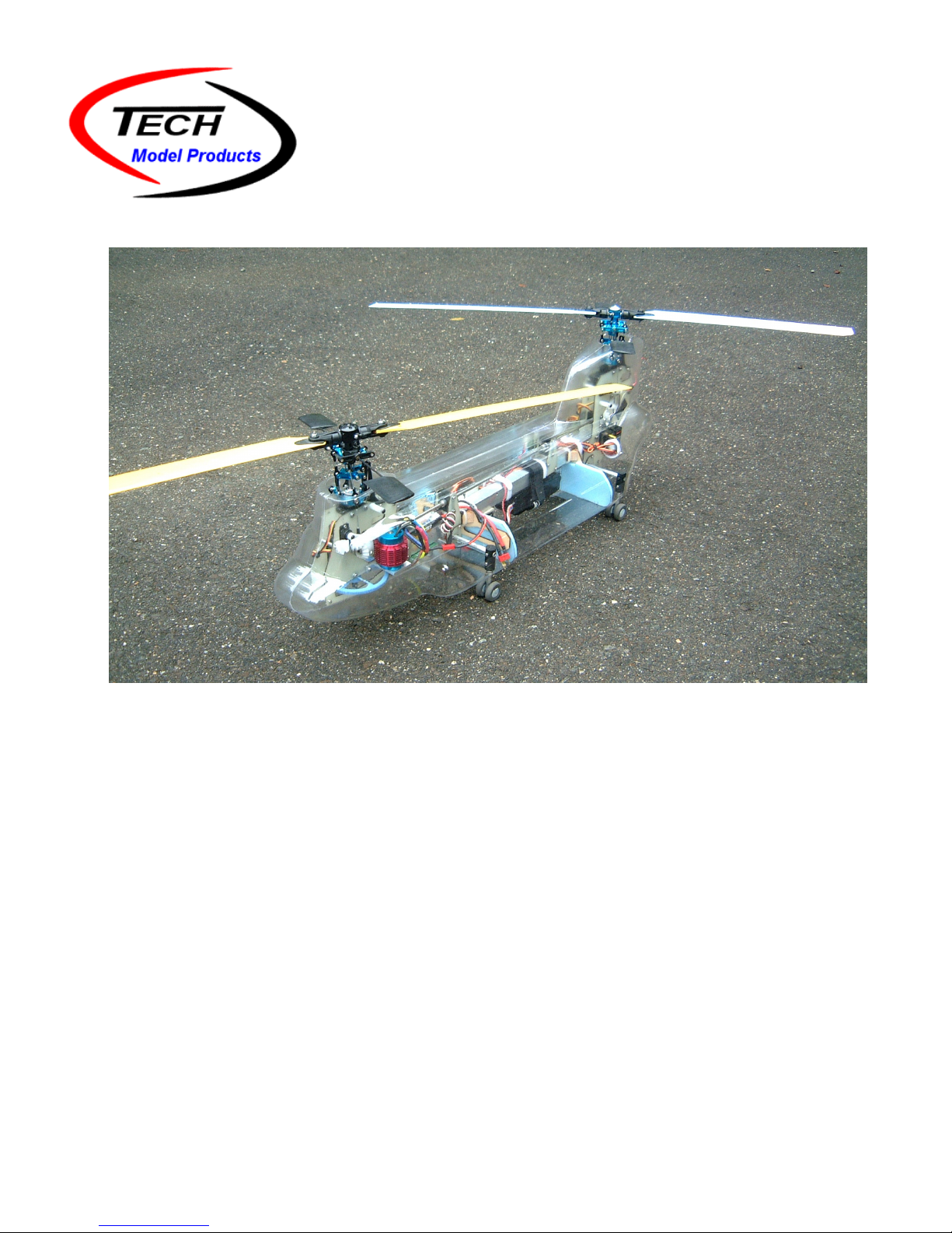
Twinn Rexx Assembly Manual
Introduction
The Twinn Rexx is a second-generation tandem helicopter that incorporates the latest components that
current technology can offer. It’s flight performance and capabilities far exceed that of any other tandem
model available on the market today. It’s sturdy construction has been designed to be easily repaired and
maintained and uses many common-place TRex 450 parts. Welcome to tandem country !
Safety Notice
The Twinn Rexx tandem helicopter is not a toy and can cause severe injury or death if not properly assembled
or operated. It is not for beginners and should only be assembled/operated by those experienced and
qualified. Eye protection is recommended anytime the rotors are turning.
Other Documentation
See the Twinn Rexx support section on our website for additional information and documents.
Tech Model Products L.L.C. • 800 Village Walk # 172 • Guilford CT 06437 • www.techmodelproducts.com
Rev B 4/03/10
Page 2

Specifications
Shaft to Shaft Distance 20.25 inches
Weight (no body or battery) 1160 grams (approximate)
Motors 300W - 500W 3S or 4S (2500KV 11T pinion on 4S)
Servos 6 - HS65 or HS65MG
Receiver 6 channel
Yaw gyro Gy240 or GY401 (with 7+ channel radio)
DCP gyro Gy240
BEC 5V 3.5 Amp min.
ESC 35 Amp
Tandem controller Tech TH-2 GP + extender board + mounting plate
Rotor heads 2 - Align plastic/metal
Rear main shaft Stock Align 450 shaft
Front main shaft Custom
Blades 315, 325 or 335
Main drive gear Stock Align main gear
Assembly Notes:
1. All metal to metal fasteners must use medium (blue) thread locker. DO NOT USE THREAD LOCKER
ON PLASTIC PARTS. Thin CA should be used for locking metal to plastic parts together.
2. All of the M2.5x30 frame screws should enter the frame from the left side. That is the screws heads
are on the left and the nuts are on the right.
Recommended Tools/Materials
Tools Required: Materials Required:
Safety Goggles/Face shield Acetone (used as degreasing agent)
Drill - small drill bits - 1mm, 2mm etc. Thread locker (medium - Loctite 242)
Marking pen (Sharpie etc) Pinion glue (Loctite 609)
Hobby knife #11 blade Thin CA
Rulers - caliper etc. Silicone rubber or Goop glue
Soldering iron - electronics solder Double-sided servo tape
Wire cutter/stripper Misc. tywraps
Pitch gauge 26 gage servo wire
Blade balancer Misc. heat shrink tubing
Misc. hand tools 22 gage hookup wire
Electrical tape
Tech Model Products L.L.C. • 800 Village Walk # 172 • Guilford CT 06437 • www.techmodelproducts.com
Rev B 4/03/10
Page 3

1. Front Frame - Assembly
Parts: Qty: Description:
TW-100-L 1 Front left main frame side plate
TW-100-R 1 Front right main frame side plate
TW-108 2 Main shaft bearing blocks
TW-109 1 Driveshaft bearing block w/M2x6 mounting screw
TW-111 1 Anti-rotation bracket w/screws (Align 1082 or 1236 modified)
TW-500 2 Main shaft bearings - 5x11x5mm (T-HS1028)
TW-501 1
TW-502 1 Driveshaft block bearing - 5x10x4 flanged
TW-301 1 Miter gear
TW-302 1 Miter gear aluminum sleeve
TW-304 1 Front main shaft
TW-305 1 Main shaft locking collar w/setscrew.
TW-306 1 Main drive gear (Align 1057 or 1218)
TW-307 1 Front main shaft ring (T-HB6003)
TW-308 1 Front one-way shaft (Align HZ026)
TW-311 1 M2x20 SH SS Miter gear mounting screw w/M2 locknut
TW-312 1 M2x10 SH Main gear mounting screw w/M2 locknut
TW-200-1 4 M2.5 x 20mm frame spacer
TW-200-2 8 M2.5 x 5 slotted screw
TW-200-5 6 M2.5 x 30 slotted screw
TW-200-6 11 M2.5 SS washer
TW-200-7 5 M2.5 locknut
1. Attach the four frame spacers to the front right frame side (TW-100-R) with four M2.5 x 5 screws. Use
thread locker. See Figure 1a.
2. Attach the front left frame side (TW-100-L) to the right side assembly with four M2.5 x 5 screws. Use
thread locker. See Figure 1b.
3. Add the two main shaft bearing blocks (TW-108) with four M2.5 x 30 slotted screws. The bearings
face outwards (top bearing faces up and bottom bearing faces down). Use three M2.5 locknuts and
six M2.5 washers. Be sure the bearing blocks are parallel to the top of the frame sides and to each
other. Leave the bottom block rear screw without a nut and washers for now. Insert the two bearings
(TW-500). See Figure 1c.
The top front block screw must be trimmed so approximately 1mm of threads extend past the locknut.
This is for clearance with the servo linkage . See Figure 1d.
4. Add the driveshaft bearing block (TW-109) with two M2.5 x 30 slotted screws. The bearing faces
towards the front. Use two M2.5 locknuts and four M2.5 washers.
Secure the bearing (TW-502) with the M2x6 machine screw. Apply some thin CA to the threads to
lock into place.
5. Slide the miter gear aluminum sleeve (TW-302) into the miter gear (TW-301) so the mounting holes
line up. Insert the M2x20 mounting screw to keep them aligned. Apply a small amount of thin CA to
lock them together. Allow to cure. Keep the M2x20 mounting screw in place without the nut for now.
6. Slide the front main shaft (TW-304) through the top bearing and through miter gear/sleeve assembly.
The gear teeth face downward. Continue sliding the shaft through the bottom bearing, through the
shaft ring (TW-307), and finally through the main gear/one-way assembly (TW-306, TW-308, TW-
501). Attach the main gear to the shaft with the M2x10 screw and locknut. Be sure the inside of the
shaft ring is sitting on the outside of the one-way shaft.
Leave the miter gear unfastened for now. The screw will be added after the rotors timing is set.
Tech Model Products L.L.C. • 800 Village Walk # 172 • Guilford CT 06437 • www.techmodelproducts.com
One-way bearing - HFO-612 (T-HS1229) - Assembled into main gear
Rev B 4/03/10
Page 4

7. Add the main shaft locking collar. Use thread locker. Add the anti-rotation bracket (TW-111). Apply
some thin CA to the threads to lock into place. See Figures 1e...1h.
2. Rear Frame - Assembly
Parts: Qty: Description:
TW-101-L 1 Rear left main frame side plate
TW-101-R 1 Rear right main frame side plate
TW-105 2 Landing gear locking plates
TW-108 2 Main shaft bearing blocks
TW-109 1 Driveshaft bearing block w/M2x6 mounting screw
TW-111 1 Anti-rotation bracket w/screws (Align 1082 or 1236 modified)
TW-301 1 Miter gear
TW-302 1 Miter gear aluminum sleeve
TW-303 1 Rear main shaft (Align 1011)
TW-311 1 M2x20 SH SS Miter gear mounting screw w/M2 locknut
TW-400 1 LG cross beam
TW-500 2 Main shaft bearings - 5x11x5mm (T-HS1028)
TW-502 1 Driveshaft block bearing - 5x10x4 flanged
TW-203-1 6 M2.5 x 20mm frame spacer
TW-203-2 8 M2.5 x 5 slotted screw
TW-203-5 6 M2.5 x 30 slotted screw
TW-203-6 12 M2.5 SS washer
TW-203-7 6 M2.5 locknut
TW-203-8 4 M2.5 x 8 slotted screw
1. Attach the four frame spacers to the rear right frame side (TW-101-R) with four M2.5 x 5 screws. Use
thread locker. See Figure 2a.
2. Attach the rear left frame side (TW-101-L) to the right side assembly with four M2.5 x 5 screws. Use
thread locker. See Figure 2b.
3. Add the two main shaft bearing blocks (TW-108) with four M2.5 x 30 slotted screws. The bearings
face outwards (top bearing faces up and bottom bearing faces down). Use four M2.5 locknuts and
eight M2.5 washers. Be sure the bearing blocks are parallel to the top of the frame sides and to each
other. Insert the two bearings (TW-500). See Figure 2c.
The top front block screw must be trimmed so approximately 1mm of threads extend past the locknut.
This is for clearance with the servo linkage . See Figure 2d.
4. Add the driveshaft bearing block (TW-109) with two M2.5 x 30 slotted screws. The bearing faces
towards the rear. Use two M2.5 locknuts and four M2.5 washers.
Secure the bearing (TW-502) with the M2x6 machine screw. Apply some thin CA to the threads to
lock into place.
5. Slide the miter gear aluminum sleeve (TW-302) into the miter gear (TW-301) so the mounting holes
line up. Insert the M2x20 mounting screw to keep them aligned. Measure the distance from the end
of the sleeve to the top of the gear (top is opposite the end with teeth). The sleeve should stick out
about 0.1 inches above the top. Flip the sleeve over and measure again. Use the configuration that
has the closest measurement to 0.1 inches.
Apply a small amount of thin CA to lock the sleeve and gear together. Allow to cure. Remove the
M2x20 mounting screw.
Tech Model Products L.L.C. • 800 Village Walk # 172 • Guilford CT 06437 • www.techmodelproducts.com
Rev B 4/03/10
Page 5

6. Slide the rear main shaft (TW-303) through the top bearing, bottom bearing and through the miter
gear/sleeve assembly. The gear teeth face downward. Secure the miter gear/sleeve to the shaft
with a M2x20 screw and locknut . The screw head should be in the recessed side of the gear.
Add the main shaft locking collar. Use thread locker. Add the anti-rotation bracket (TW-111). Apply
some thin CA to the threads to lock into place. See Figure 2e.
7. Insert a M2x12 SS dowel pin (TW-406) into the LG cross beam (TW-400). Center the pin inside the
beam shaft. Slide the shaft through both sides of the frame sides. Insert a second M2x12 SS dowel
into the LG cross beam. Center the pin inside the beam shaft.
8. Slide a landing gear locking plate (TW-105) onto each side of the frames. Attach the two M2.5 x
20mm frame spacers with the four M2.5 x 8 slotted screw. Use thread locker. See Figures 2f... 2j.
3. Rear DS Support - Assembly
Parts: Qty: Description:
TW-103 2 Driveshaft support plates
TW-106 1 Driveshaft support bearing block w/M2x6 mounting screw
TW-110 1 Main frame aluminum tube
TW-503 1 Driveshaft support bearing - 8x12x3.5 flanged
TW-202-1 2 M2.5x1 Nylon washer
TW-202-2 4 M2.5 x 30 slotted screw
TW-202-3 4 M2.5 locknut
TW-202-4 8 M2.5 SS washer
1. Draw a mark on the main frame aluminum tube (TW-110) with a marking pen 8.5 inches from the front
edge. Draw the mark on all four sides of the tube. This is the CG (center of gravity) location for the
aircraft.
2. Attach the driveshaft support plates (TW-103) to the frame tube with two M2.5 x 30 slotted screws.
Use two M2.5 locknuts and four M2.5 washers. The Nylon washers go between the left plate and the
frame tube to shim the plate outward.
3. Add the driveshaft support bearing block (TW-106) with two M2.5 x 30 slotted screws. Use two M2.5
locknuts and four M2.5 washers. Insert the bearing (TW-503) so it faces towards the front. Secure
the bearing with the M2x6 machine screw. Apply some thin CA to the threads to lock into place. See
Figures 3a... 3b.
4. Front DS/LG Support - Assembly
Parts: Qty: Description:
N/A 1 Main frame tube assembly from step 3
TW-104 2 Front landing gear/driveshaft mounting plates
TW-105 2 Landing gear locking plates
TW-106 1 Driveshaft support bearing block w/M2x6 mounting screw
TW-400 1 LG cross beam
TW-406 2 M2x12 SS dowel pin
TW-503 1 Driveshaft support bearing - 8x12x3.5 flanged
TW-201-1 2 M2.5x1 Nylon washer
TW-201-2 1 M2.5 x 20mm frame spacer
Tech Model Products L.L.C. • 800 Village Walk # 172 • Guilford CT 06437 • www.techmodelproducts.com
Rev B 4/03/10
Page 6

TW-201-3 2 M2.5 x 8 slotted screw
TW-201-4 4 M2.5 x 30 slotted screw
TW-201-5 4 M2.5 locknut
TW-201-6 6 M2.5 SS washer
1. Attach the two front landing gear/driveshaft mounting plates (TW-104) to the main frame tube
assembly using one M2.5 x 30 slotted screw. The screw goes into the top front section of the
mounting plates. Use a M2.5 locknut and two M2.5 washers. A Nylon washer goes between the left
plate and the frame tube to shim the plate outward. Leave the screw loose.
2. Insert a M2x12 SS dowel pin (TW-406) into the LG cross beam (TW-400). Center the pin inside the
beam shaft. Slide the shaft through both sides of the mounting plates. Insert a second M2x12 SS
dowel pin into the LG cross beam. Center the pin inside the beam shaft. See Figure 4a.
3. Slide a landing gear locking plate (TW-105) onto each side of the mounting plates. Attach them with a
M2.5 x 30 slotted screw and M2.5 locknut. A Nylon washer goes between the left plate and the frame
tube. No other washers are used here. Attach the M2.5 x 20mm frame spacer with the two M2.5 x 8
slotted screw. Use thread locker. Tighten both M2.5 x 30 slotted screws.
4. Add the driveshaft support bearing block (TW-106) with two M2.5 x 30 slotted screws. Use two M2.5
locknuts and four M2.5 washers. Insert the bearing (TW-503) so it faces towards the rear. Secure
the bearing with the M2x6 machine screw. Apply some thin CA to the threads to lock into place. See
Figures 4b... 4d.
5. Completing the frame - Assembly
Parts: Qty: Description:
N/A 3 Assemblies from steps 1 - 4
TW-102 2 Main frame shim plates
TW-300 1 Hollow SS driveshaft w/support sleeves
TW-301 2 Miter gear
TW-302 2 Miter gear aluminum sleeve
TW-310 1 Motor mount
TW-311 2 M2x20 SH SS Miter gear mounting screw w/M2 locknut
TW-314 3 Motor mount shim plates (optional)
TW-200-5 4 M2.5 x 30 slotted screw
TW-200-6 5 M2.5 SS washer
TW-200-7 1 M2.5 locknut
TW-200-8 3 M2.5 nut
TW-203-5 4 M2.5 x 30 slotted screw
TW-203-6 8 M2.5 SS washer
TW-203-7 8 M2.5 locknut
1. Attach the front frame assembly and motor mount to the main frame assembly with four M2.5 x 30
slotted screws. A main frame shim plate goes between the left side and the frame tube to shim the
frame side outward. Fasten the motor mount screws using three M2.5 nuts. Use thread locker. No
washers are used under the screw heads on the motor mount. The top rear section of the frame
sides should be square with the frame tube. Note: Depending on the motor used, 1 or more motor
mount shim plates (TW-314) may be needed. The plates stack between the frame side and the motor
mount. See Figures 5a... 5b.
Tech Model Products L.L.C. • 800 Village Walk # 172 • Guilford CT 06437 • www.techmodelproducts.com
Rev B 4/03/10
Page 7

2. For the remaining two miter gears, slide the miter gear aluminum sleeves (TW-302) into the miter
gears (TW-301) so the mounting holes line up. Insert the M2x20 mounting screws to keep them
aligned. Apply a small amount of thin CA to lock them together. Allow to cure. Remove the M2x20
mounting screws.
3. Insert the driveshaft (DS) through the rear DS support bearing. Next, slip the two support sleeves on.
Continue sliding the DS forward through the front support bearing. While holding the front miter gear
assembly in place, slide the DS into it and insert a M2x20 mounting screw to keep them together.
Slide each support sleeve such that they are centered within the race of each DS support bearing.
Mark the locations of the sleeves on the DS. Remove the DS and sleeves. Degrease the entire DS
and inside the sleeves with a suitable cleaner such as Acetone. See Figures 5c... 5d.
Re-install the DS as described above. Secure the miter gear/sleeve to the DS with a M2x20 screw
and locknut. The screw head should be in the recessed side of the gear. Glue the sleeves into place
using a suitable compound (loctite 609 recommended). Allow to cure.
4. While holding the rear miter gear assembly in place, slide the rear frame assembly into place on the
frame tube. A main frame shim plate goes between the left side and the frame tube to shim the frame
side outward. Loosely attach the assembly with four M2.5 x 30 slotted screw. Use four M2.5 locknut
and eight M2.5 SS washers. Secure the miter gear/sleeve to the DS with a M2x20 screw and locknut.
The screw head should be in the recessed side of the gear.
5. Snug either of the two diagonal M2.5 x 30 slotted screws so that the rear frames can be adjusted but
stay in place as well. Adjust the rear frames so that they are square to the main tube and the DS has
a maximum end to end play of 0.5mm (0.02 inches). Tighten the four M2.5 x 30 slotted screws.
See figures 5e... 5f.
6. Setting the timing of the rotors - Assembly
Parts: Qty: Description:
TW-311 1 M2x20 SH SS Miter gear mounting screw w/M2 locknut
1. The front and rear rotor heads must be phased by 90 degrees to prevent the blades from
colliding. This is done by setting the holes on top of the two main shafts 90 degrees to each other.
Remove the mounting screw from the front vertical miter gear. While holding the front main shaft in
place, lift the front vertical miter gear (disengage from the other gear) and rotate the rear shaft so the
hole is 90 degrees (perpendicular) to the front shaft. The trick is to keep the front shaft and miter gear
mounting holes aligned while this is done.
Secure the front miter gear/sleeve to the DS with a M2x20 screw and locknut. The screw head should
be in the recessed side of the gear.
7. Landing gear - Assembly
Parts: Qty: Description:
TW-401 4 LG strut
TW-402 4 LG strut mount
TW-403 4 LG axel
TW-404 8 LG 1" wheel
TW-405 8 M2x16 SH strut mounting screw; M2 nut
Tech Model Products L.L.C. • 800 Village Walk # 172 • Guilford CT 06437 • www.techmodelproducts.com
Rev B 4/03/10
Page 8

1. The two rear landing gear (LG) strut mounts (TW-402) need to be trimmed slightly for clearance with
the CH47 body. The bottom is trimmed so that it tapers upwards around 5mm front to back. This
step can be done later when adding the body. See figure 7a.
2. Attach two LG strut mounts (TW-402) to each of the LG cross beams (TW-400) with four M2x16 SH
and M2 nuts. Use thread locker. Apply some thin CA to each joint (TW-400 & TW-402)) to lock into
place.
3. Attach the four LG struts (TW-401) to the LG strut mounts with four M2x16 SH and M2 nuts. Use
thread locker.
4. Add the wheels to the LG struts. The solid side of the wheel hubs face outward. The wheels are
pressed onto axels. Do one side at a time. Leave some play between the wheel and the strut to
allow the wheels to spin freely. See figure 7b.
5. Adjust the LG struts/LG cross beams so that the struts are square with the ground. Use a small
amount of silicone rubber or Goop type glue to lock the dowel pins into place. CA is not
recommended for this application. Apply the glue such that it fills the spaces between the pin and the
locking plates. Allow to cure.
8. Servos - Assembly
Parts: Qty: Description:
Servos 6 Hitec HS-65MG or HS-65
TW-200-3 6 M2 x 8 Phillips servo mounting screw
TW-200-4 6 M2 locknut
TW-203-3 6 M2 x 8 Phillips servo mounting screw
TW-203-4 6 M2 locknut
1. Mount the six balls (TW-114) to the servo arms with the 2mm screws provided. Use the single servo
arm that has the second hole 13mm from center. Mount the balls in the second hole on the arm. Five
of the balls are mounted downward (toward the servo) and one is mounted upward. Optionally, a
2mm nut can be added to each screw for insurance (not included in kit).
2. Center each servo with the radio and mount the servo arms to the servos. Mount the servos to the
frame using the M2 x 8 Phillips screws and locknuts. Note: The rear "E" servo can be mounted two
ways. It can be mounted up top for use without the body and the stock link can be used (same as
front link). For use with the body, Mount the servo in the lower section and the "E" link must be used.
See figures 8a... 8f.
Note: All servos should be centered to the same channel for now. Final adjustments will be made
later using the TH-2 controller centering.
9. Links - Assembly
Parts: Qty: Description:
TW-112 2 Link set (Align 1119)
TW-113 1 Front P link kit
TW-115 1 Rear E link kit
1. Assemble the two link sets (front and rear) as shown in the Align SE kit manual. See the Twinn Rexx
support page on the website for more info.
Tech Model Products L.L.C. • 800 Village Walk # 172 • Guilford CT 06437 • www.techmodelproducts.com
Rev B 4/03/10
Page 9

2. Assemble the front "P" link (TW-113). Be sure the rod threads are half way or more into the plastic
links.
3. Assemble the rear "E" link (TW-115). Be sure the rod threads are half way or more into the plastic
links. Note: the "E" link only needs to be used if the rear "E" servo is mounted in the lower section of
the frame. See the "E link" specification for adding the proper bend to it.
10. Rear rotor head - Assembly
Parts: Qty: Description:
TW-800 1 Flybar paddles
TW-801 2 M3x16 SH screws w/locknuts for main blades
TW-803 1 Flybar travel limit kit
TW-804 2 Feathering screws (M2x5 SH)
TW-805 2 Feathering washer
TW-806 1 Rotor head feathering shaft (Align 1003)
TW-807 2 Rotor head spacers
TW-808 1 Flybar (Align 1006)
N/A 1 Rotor head parts (See parts list for more info)
Note: The rear rotor head is built the same way as a stock T-Rex. The only difference is that a
"flybar limiter" is added to limit the travel of the flybar so it can’t hit the rear tower.
1. Attach the flybar limiter (TW-803) to the main rotor housing (Align 1071 plastic, 1197 metal). If the
metal (1197) version is used a 1mm hole (approximately) needs to be drilled for the anchor wire. The
hole is drilled about 3mm up from the top of the flybar slot. See figures 10a... 10b.
2. Assemble the rear rotor head as shown in the Align SE kit manual. See the Twinn Rexx support page
on the website for more info.
3. Be sure the flybar paddles are centered. Any side to side slop in the flybar cage should be removed
with shim washers as required. This step is important towards minimizing sources of vibration.
4. Attach the rear rotor head to the rear main shaft.
5. Balance the rear main blades using a blade balancer. Try to get them as perfect as possible since
this will reduce vibration. Leave the blades off for now.
11. Front rotor head - Assembly
Parts: Qty: Description:
TW-800 1 Flybar paddles
TW-801 2 M3x16 SH screws w/locknuts for main blades
TW-804 2 Feathering screws (M2x5 SH)
TW-805 2 Feathering washer
TW-806 1 Rotor head feathering shaft (Align 1003)
TW-807 2 Rotor head spacers
TW-808 1 Flybar (Align 1006)
N/A 1 Rotor head parts (See parts list for more info)
Note: The front rotor head is built to rotate counter-clockwise (CCW). This is opposite of a stock
TRex.
1. Assemble the front rotor head. Refer to the notes below. See figures 11a... 11b.
• The main blade grips are flipped.
Tech Model Products L.L.C. • 800 Village Walk # 172 • Guilford CT 06437 • www.techmodelproducts.com
Rev B 4/03/10
Page 10

• The upper mixer arms are flipped and the balls are mounted on the opposite side. For the
plastic arms, a small amount of the plastic needs to be shaved off for clearance with the ball.
• The washout base is mounted upside down. For the metal version, the bushing needs to be
either trimmed (cut away) or pressed out and then pressed in on the other side. The other
option is to use the older style metal washout base that is symmetrical on both sides (Align
1143)
2. Attach the front rotor head to the front main shaft.
3. Verify that the front and rear heads are phased 90 degrees to each other.
4. Balance the front main blades using a blade balancer. Try to get them as perfect as possible since
this will reduce vibration. Leave the blades off for now.
12. Electronics/Electrical - Assembly
Parts: Qty: Description:
N/A 1 Motor with mounting screws
N/A 1 ESC
N/A 1 BEC (5V 3.5amp minimum)
N/A 1 Yaw gyro
N/A 1 DCP gyro
N/A 1 Receiver
N/A 1 TH-2GP controller + mount + extender
N/A 1 Deans micro connector set M/F
N/A 1 Deans Ultra connector set M/F
N/A 1 36" Servo extension Male
N/A 4 12" Servo extension Male
N/A N/A 26 gage servo wire
N/A N/A 22 gage stranded hookup wire
N/A 2 Ferrite ring
Note: Refer to the Twinn Rexx wiring diagram for the instructions below.
• ESC to motor - The ESC outputs connect to the motor with bullet connectors covered with heat
shrink tubing. Mount the ESC up front close to the motor with it’s heat sink against the main frame
tube. The motor attaches to the motor mount with two screws and washers. Verify the mesh with the
main drive gear is smooth all around it’s circumference.
• ESC to receiver - The ESC control input connects to the receivers throttle channel. The red power
lead must be removed from the connector housing and covered with heat shrink tubing or tape. This
is because an external BEC supplies power to all of the onboard electronics. Add a ferrite ring the
control lead if needed.
• ESC to battery - The ESC power inputs connect to the battery with Deans ultra connectors. The
male end is on the ESC side.
• BEC to battery - The BEC power inputs connect to the battery with Deans micro connectors. The
male end is on the BEC side. This is so the electronics can be powered without the ESC and motor.
This is convenient during set up. Mount the BEC up front near the ESC. The output of the BEC
should have a ferrite ring installed.
• Receiver - Mount the receiver onto the rear of the frame away from the ESC, BEC etc. For safety, a
redundant power connection is made to the BEC output (5v). Use a spare channel if available or a
Tech Model Products L.L.C. • 800 Village Walk # 172 • Guilford CT 06437 • www.techmodelproducts.com
Rev B 4/03/10
Page 11

"Y" cable if not. A male servo lead is connected to the BEC output (5V) to supply the power.
Apply a layer electrical tape over the receiver connectors to prevent them from coming loose. Wrap
the receiver with foam rubber sheet and attach to the frame with tywraps
• TH-2 - Mount the TH-2 onto the rear of the frame away from the ESC, BEC etc. It is best to mount the
TH-2 unit to a TH-2 mounting plate with double sided tape. Then the assembly is mounted to the
frame with screws and standoffs (not included in base kit).
For safety, two power connections are made to the BEC output (5v). Use any two of the spare header
connectors (on the TH-2). Male servo leads plug into the headers and are connected to the BEC
output (5V) to supply the power.
The rear servos plug directly into the TH-2 rear A, E, P outputs.
An extender board is mounted to the front frame and the front servos plug into the extender board A,
E, P outputs. The extender board is connected to the TH-2 with a dual male servo extension to the
TH-2s front A, E, P servo outputs. The extender board power inputs are connected directly to the
BEC output (5V) with 22 gage stranded wire..
The TH-2 A, E, P inputs are connected directly to the receivers aileron, elevator and pitch outputs.
• Yaw gyro - Mount the yaw gyro onto the bottom side of the frame tube with double-sided servo tape.
Mount it as close a possible to the CG (center of gravity). The gyro input connects to the receivers
rudder output. The gyro output connects to the TH-2s rudder input. An extension will probably be
needed. Apply tape or heat shrink tubing over the connections to prevent them from coming apart.
• DCP gyro - Mount the DCP gyro onto the right side of the frame tube with double-sided servo tape.
Mount it as close a possible to the CG (center of gravity). The gyro input connects to the receivers
CH5 output. The gyro output connects to the TH-2s CH5 input. An extension will probably be
needed. Apply tape or heat shrink tubing over the connections to prevent them from coming apart.
See figures 12a... 12f.
13. Radio/Electronics - Setup
• ESC - Program the ESC for helicopter use. Set the cut-off voltage feature off or to the lowest setting.
• Yaw gyro - Set the gyro gain to 50% for now and the mode to "rate mode". The direction setting will
be set and verified in a later step.
• DCP gyro - Set the gyro gain to 50% for now and the mode to "rate mode". The direction setting will
be set and verified in a later step. Also, the mode will be switched to "heading hold" later after the
helicopter is lift balanced.
• Transmitter - Turn all mixing features off in the transmitter. Swashplate type is for mechanical mixing.
a. Set all channels ATV (end point) to 100/100 except for CH5. Set the CH5 ATV (end point) to
50/50.
b. Setup a PMIX (programmable mix) between the elevator channel and CH5. The elevator is
the master and CH5 is the slave. Set the mixing gain to 70/70. This will allow changes to the
DCP gain at the flying site by just changing the gain in the transmitter.
c. Setup expo of 30% for the aileron, elevator and rudder channels. Set it to reduce sensitivity
at center. Some radios will have a positive value and others will be negative (Futaba).
Tech Model Products L.L.C. • 800 Village Walk # 172 • Guilford CT 06437 • www.techmodelproducts.com
Rev B 4/03/10
Page 12

d. Set the throttle curve (normal mode) to 0, 25, 50, 75, 100.
e. Set the pitch curve (normal mode) to 0, 25, 50, 75, 100.
• TH-2 - load the Twinn Rexx constants settings into the TH-2. The constants file can be downloaded
from the Twinn Rexx support page.
a. Set all input gains to 50% except DCP is 25% to 30%.
b. DCP source is CH5.
• Final calibration - Turn on the transmitter (TX) and power-up the helicopter without the ESC/motor
powered. Set the TX throttle stick to half way. Note: TX reversing switches may need adjusting.
a. Adjust the TH-2 centering constants so the servo arms are at right angles to the swashplate.
This a back and forth try and see procedure. It only needs to be done once.
b. Adjust the length of the lowest links so each swashplate is level.
c. Install both sets of main blades. Adjust the length of the lowest links/ top most links so that
there is zero degrees of pitch in the main blades. Use a pitch gauge.
d. Set the overall up/down swashplate travel in the TX using the swashplate menu. Adjust the
pitch gain setting such that there is no binding of the swashplate at full low stick and full high
stick.
e. Set the top end pitch using the pitch curve (normal mode) to about eight (8) degrees.
f. Set the low end pitch using the pitch curve (normal mode) to about minus four (-4) degrees.
g. Verify both rotors and both sets of blades have zero pitch at half stick using a pitch gauge.
Do this same test at full low stick and full high stick.
h. Yaw gyro direction - Verify the direction setting on the yaw gyro is correct. This is done by
rotating the model along it’s yaw axis and observing if the motion is being corrected by the
gyro. Forcing a right yaw should cause the gyro to apply left yaw and visa versa.
i. DCP gyro direction - Verify the direction setting on the DCP gyro is correct. This is done by
rotating the model along it’s DCP axis and observing if the motion is being corrected by the
gyro. Forcing the nose down should cause the gyro to apply aft DCP (front swashplate up
and rear swashplate down). Temporarily setting the gyro gain higher will make it easier to
see the motion of the servos etc. Be sure the DCP gyro is set to "rate" mode for now.
14. Initial Run-up
Remove the rotor blades. Wear eye protection and power-up the radio and helicopter in a suitable
location. Advance the throttle slowly to about 1/4 stick. Notice the following.
• There should be no vibration. If vibration is present, find the source and correct it before
going further.
• The drive-train should be running smoothly and quietly. Correct if not.
• The flybars should be flying level. Correct if not.
• The cyclic controls should be operating properly. Correct if not.
Tech Model Products L.L.C. • 800 Village Walk # 172 • Guilford CT 06437 • www.techmodelproducts.com
Rev B 4/03/10
Page 13

• Install the front rotor blades. Run it up slowly and track the blades using the uppermost
links. Check for vibration and correct as needed. Remove the front rotor blades.
• Install the rear rotor blades. Run it up slowly and track the blades using the uppermost
links. Check for vibration and correct as needed. Do not over-speed the rotor (1500
RPM max).
• Re-install the front rotor blades. Verify the front and rear rotors are phased by 90
degrees. Correct as needed.
• Verify the driveshaft end to end play is no more than 0.5mm ( 0.020 inches)
15. First flight
Wear eye protection and power-up the radio and helicopter at the flying site. A hard surface is recommend.
• Lift balancing - Lift off the helicopter about six inches. It should have equal lift in each rotor. If so,
both rotor discs will be flying in the same plane. Correct if needed by adding pitch the low rotor or by
reducing pitch in the high rotor. This is done by adjusting the uppermost links a half turn at a time.
• DCP gyro HH mode - With the helicopter properly lift balanced, switch the DCP gyro into "heading
hold" mode. This will make the helicopter fly much smoother and be more enjoyable. Be sure to
maintain a DCP gain of 25% to 30% (in the TH-2). This will provide the gyro with enough control
power to overcome most disturbances.
16. General Flying Notes
• Tandems are inherently stable helicopters. When setup properly it will fly hands off for quite some
time. Unlike single rotor helicopters, a tandem won’t drift off in some direction and head for the
ground. It will just happily float around.
• Keep the rotor head speed lower than that of a single rotor helicopter. The maximum recommended
RPM is about 2000. An RPM of 1800 to 1900 is good. The two rotors offer plenty of gyroscopic
stability. Higher head speed will generate higher levels of vibration. This can reach levels that may
produce positive feedback into the yaw gyro. This condition can make the helicopter uncontrollable.
• All tandems experience Front Rotor Vortex Interference (FRVI). It occurs at low flying speeds and at
high angles of attack. From a stationary hover gaining forward speed, at some speed the front rotor
vortex will begin to extend back and interfere with the lift generated by the rear rotor. This will cause
the tail of the aircraft to drop. To correct, apply forward stick and some power. The sooner you apply
the correction the smaller the effect of FRVI will be.
The DCP gyro will handle this condition for most flight conditions. It will stay ahead and compensate
automatically up to a point. Understand that there are many flight conditions and attitudes beyond the
control power of the gyro to compensate. It is recommended that you practice with the DCP gyro in
"rate " mode to develop a "feel" for when these conditions occur and the reflexes to compensate.
Practice will allow you to recognize the onset of FRVI and allow you to recover or even prevent an
occurrence.
• Tandems require more forward stick to be held during forward flight. This will induce a steady state
yaw to the left due to the DCP. Yaw compensation can be used to counter this effect. This can be
done by the TH-2 controller or by a programmable mix in your transmitter (elevator to rudder).
Tech Model Products L.L.C. • 800 Village Walk # 172 • Guilford CT 06437 • www.techmodelproducts.com
Rev B 4/03/10
 Loading...