

Page 1
ST-44 USER’S MANUAL
Page 2

ST-45 User's Manual
Declaration of Conformity No. 27/2008
Hereby, we declare under sole responsibility that the ST-45
230V 50Hz thermoregulator manufactured by TECH, ul. St.
Batorego 14, 34-120 Andrychów, is compliant with the
Regulation by the Ministry of Economy. (Journal of Laws Dz.U.
155 Item 1089) of July 21, 2007 implementing provisions of the
Low Voltage Directive (LVD) 2006/95/EC of January 16, 2007.
The ST-45 controller has been tested for electromagnetic
compatibility (EMC) with optimal loads applied.
For compliance assessment, harmonized standards were
used:
PN-EN 60730-2-9:2006.
Co-owners:
Paweł Jura, Janusz Master
-2-
Page 3

TECH
ATTENTION!
HIGH VOLTAGE!
Make sure the regulator is unplugged before
working on the power supply (cable connections,
device installation, etc.)!
All mounting works must only be carried out by
qualified electricians.
Before activating the controller, measure the motor
resetting efficiency, check the boiler and inspect
wire insulation.
CAUTION
THE DEVICE MAY BE DAMAGED IF STRUCK BY A
LIGHTNING. MAKE SURE IT IS UNPLUGGED
DURING STORMS
-3-
Page 4
ST-45 User's Manual
I.Description
The ST-45 temperature regulator is intended for use with central heating
boilers. It is used to control the water circulation pump, hot consumption
water pump, floor heating pump, mixing pump, blow (fan) and fuel
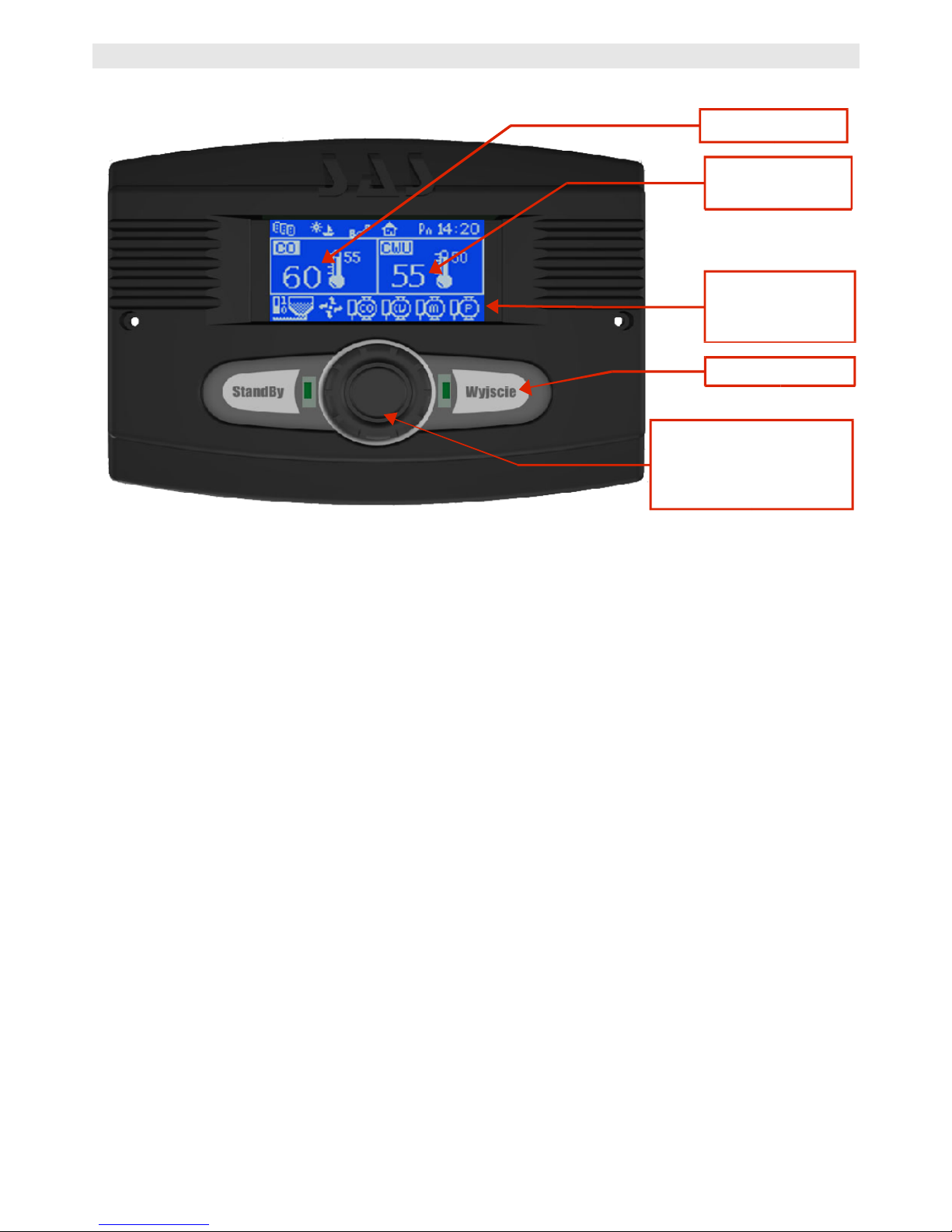
feeder. The ST-45 regulator features two modules: graphic display panel
and control panel.
The ST-45 can be used with two optional additional three-way or
four-way valve control modules. The regulator has been designed
and made for comfort.
It is very easy in use. All parameters are adjusted with a convenient
knob (encoder). The ST-45 regulator features also a graphic display that
shows the current status of the boiler.
If the furnace temperature is lower than the setpoint temperature, the
regulator is operated in its duty cycle, i.e. the blow is active and the
operation time of the fuel feeder is set by the user (both operation and
stand-by times are set).
If the furnace temperature is equal to or higher than the setpoint
-4-
Boiler Temp.
Water Heater
Temp.
Feeder; C.H.
Pump; H.C.W.
Pump; Fan
Button for accessing
submenus,
confirming settings
(encoder)
Exit
Page 5
TECH
temperature, the regulator is operated in its sustain cycle (both stand-
by and sustain mode times are to be set).
Please send all comments on the software to the boiler
manufacturer.
Your controller should be set according to your individual needs,
depending on the type of fuel and boiler used. TECH shall not be
held responsible for incorrect settings.
II.Regulator Functionality
This chapter describes regulator functionality, how to change settings
and navigate in the menu with the encoder (knob). Depending on the
mode the boiler is currently in, the display will show boiler operational
parameters. The given mode is selected by the user.
While the user is logging in, the display shows the manufacturer and the
software version.
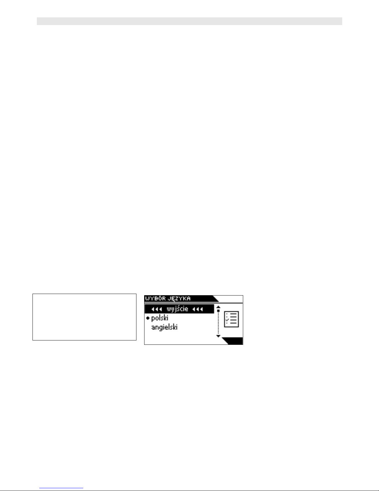
After several seconds, you can select your language. With this function,
you can change the language version.
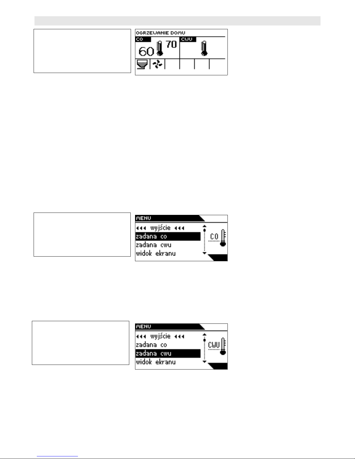
II.1.Main Page
During normal operation, the graphic display shows the main page with
the following data:
-5-
LANGUAGE VERSION
Exit
Polish
English
Page 6
ST-45 User's Manual
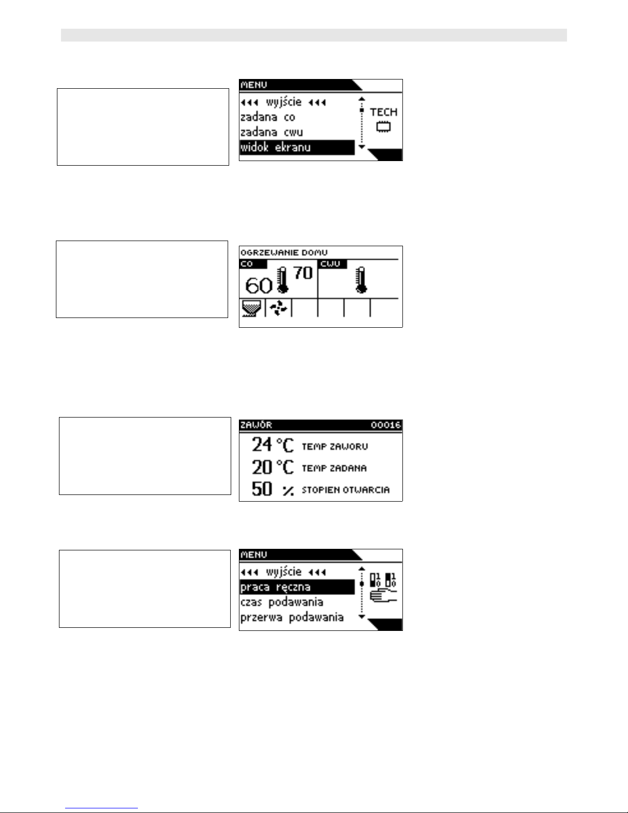
Boiler temperature (actual to the left; setpoint to the right)
Pressing the encoder will move you to the first level. The display shows
three options of the menu. To move to next options, turn the knob
clockwise. In order to exit the menu, select EXIT (only in the edit mode)
In order to apply any changes, they need to be confirmed by pressing the
encoder on the CONFIRM message. If you do not wish to make any
changes in a given function, press the encoder on the CANCEL message.
II.2.C.H. Setpoint Temperature
With this function, you can set the boiler temperature. You can change
the boiler temperature in a range between 45°C and 80°C.
II.3.H.C.W. Setpoint Temperature
With this function, you can set the hot consumption water temperature.
You can change the boiler temperature in a range between 40°C and
75°C.
-6-
HOUSE HEATING
C.H. H.C.W.
MENU
Exit
C.H. Setpoint
H.C.W. Setpoint
Screen Display
MENU
Exit
C.H. Setpoint
H.C.W. Setpoint
Screen Display
Page 7
TECH
II.4.Screen
With this function, you can select one of three main screens to control
the thermoregulator. The C.H. screen is used for displaying the current
boiler status.
The valve 1 screen is used for displaying parameters of the first valve.
The valve 2 screen is used for displaying parameters of the second
valve.
II.5.Manual Mode
For your convenience, the regulator features a manual mode module. In
this mode, each individual element is enabled and disabled independently
of the other.
Pressing the ENCODER will enable the fuel feeder. The feeder will
operate until the ENCODER is pressed again.
-7-
MENU
Exit
C.H. Setpoint
H.C.W. Setpoint
Screen Display
HOUSE HEATING
VALVE
VALVE TEMP
SETPOINT TEMP
OPENING
MENU
Exit
Manual Mode
Feed Time
Feed Pause
Page 8

ST-45 User's Manual
Press the ENCODER to enable / disable the blow.
Press the ENCODER to enable / disable the central heating pump.
Press the ENCODER to enable / disable the (water heater) hot
consumption water pump.
Press the ENCODER to enable / disable the floor heating pump.
Press the ENCODER to enable / disable the mixing pump.
Press the ENCODER to enable / disable the alarm.
II.6.Feed Time
With this function, you can set the operation time for the fuel feeder. Set
the operation time according to the type of fuel and boiler used.
II.7.Feed Interval
With this function, you can set the stand-by time for the feeder,
depending on the type of fuel used in the boiler. Incorrect operation and
stand-by times may cause the boiler to malfunction, i.e. inability to burn
all carbon and to reach the setpoint temperature. Setting correct times
will ensure correct boiler operation.
II.8.Blow Force
With this function, you can control the fan speed. The adjustment range
is from 10 to 100% (it can be assumed that the fan operates in gears).
-8-
MENU
Exit
Manual Mode
Feed Time
Feed Pause
MENU
Exit
Blow Force
Operation Mode
Sustain Mode
Page 9
TECH
The higher the gear, the higher the speed with 10% being the minimum
and the 100% being the maximum speed of the fan.
Initially, the fan runs always at full speed so that it is possible to start it
with the motor being slightly dusty.
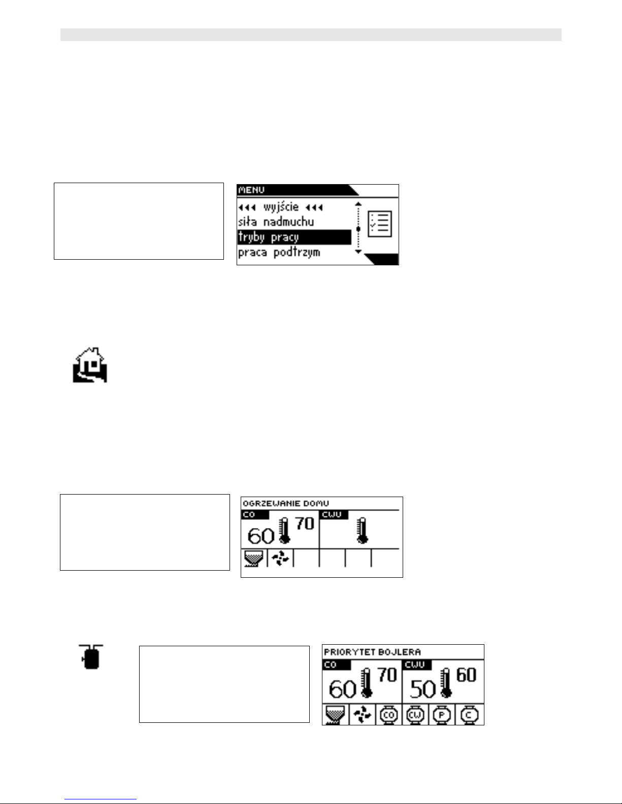
II.9.Operation Mode
With this function, you can select one out of four operation modes.
II.9.a)House Heating
If you select this option, the regulator will switch into the house heating
mode. The central heating pump starts to run above the pump activation
threshold (set to 40°C by default). Below this temperature, the pump is
shut off.
II.9.b) Water Heater Priority
-9-
MENU
Exit
Blow Force
Operation Mode
Sustain Mode
HOUSE HEATING
C.H. H.C.W.
WATER HEATER PRIORITY
C.H. H.C.W.
Page 10

ST-45 User's Manual
If you select this option, the regulator will switch into the water heater
priority mode. Activating the hot consumption water pump will cause the
regulator to switch into the water heater priority mode. In this mode, the
(hot consumption water) heater pump is activated until the set
temperature is reached. Then, the pump is shut off and the central
heating circulation pump is activated.
In order to activate the hot consumption water pump, it is necessary to
raise the setpoint temperature above the pump activation threshold (the
pump activation threshold to be adjusted in the service menu).
The temperature can be changed in the H.C.W Set function (see point
II 2).
In this mode, the fan and the feeder are operated as long as the
temperature is below 62°C to prevent the boiler from overheating. Such
condition will be maintained until the water heater setpoint temperature
is reached. When the temperature is reached, the hot consumption water
pump is shut off and the central heating pump is activated.
The central heating pump will run until the water heater temperature
drops below the setpoint value; then, the central heating pump is shut
off and the hot consumption water pump is activated.
The hot consumption water priority function consists in that the
consumption water is heated up before heating up water in radiators.
ATTENTION: the boiler should have non-return valves mounted on the
central heating pump and hot consumption water pump circuits. A valve
mounted on the pump will prevent the hot consumption water from being
discharged from the water heater. A valve mounted on the central
heating circuit will not let the hot consumption water move from the
water heater into the house circuit.
-10-
Page 11

TECH
II.9.c) Parallel Pumps
In this mode, the pumps run initially in parallel above the pump
activation threshold (set to 40°C by default). The central heating pump
continues to run and the hot consumption water pump is shut off after
the water heater setpoint temperature has been reached.
ATTENTION: in this mode, you should mount a three-way valve or a
mixing valve that will maintain different temperatures in the water heater
and in the house.
II.9.d) Summer Mode
When the function is enabled, the central heating pump is switched off
and the hot consumption water pump is activated above the pump
activation threshold (set to 40°C by default). In this mode, the hot
consumption water pump continues to run above the pump activation
threshold (set to 40°C by default). In the summer mode, the water
heater setpoint temperature is to be set. When the summer mode is
disabled, the actual temperature of the central heating and two
temperatures (actual and setpoint) of the hot consumption water are
displayed.
II.10.Sustain Mode Operation
With this function, you can set the operation time for the fuel feeder and
the fan.
-11-
SUMMER MODE
C.H. H.C.W.
Page 12

ST-45 User's Manual
II.11.Pause in Sustain Mode
With this function, you can set the pause of the feeder in the sustain
mode.
The function is used for regulating the furnace while in the sustain
mode. This is to prevent damping of the furnace when the boiler
temperature is over the setpoint value.
ATTENTION: incorrect settings may cause a continuous increase of the
temperature! Especially the Pause in Sustain Mode should not bee too
short.
II.12.Sustain Mode of Fan
In this function, you can set the operation time and the pause time for
the fan while in the burnout mode.
III.Fitter’s Menu
The fitter’s menu parameters are to be set by the boiler fitter or service
personnel provided by Sas.
-12-
MENU
Exit
Sustain Pause
Fan Sustain
Fitter’s Menu
MENU
Exit
Sustain Pause
Fan Sustain
Fitter’s Menu
MENU
Exit
Sustain Pause
Fan Sustain
Fitter’s Menu
Page 13

TECH
III.1.Factory Settings
The regulator has been pre-configured. However, it should be adjusted to
your individual needs. It is possible to return to the factory settings at
any time. By enabling factory settings, all boiler settings that you have
made will be replaced by settings made by the manufacturer. From then
on, you can again set your own operating parameters for the boiler.
III.2.Valves 1 and 2
With this function, you can set the operation time for the mixing (three-
or four-way) valve only with modules ST-61. For the valve to operate
properly and as required, it is necessary to set several parameters.
III.2.a) Registration
In this function, the fitter enters the serial number of the control module
used with the three-way valve actuator (ST-61, five-digit number
provided on the module housing). Without entering the number, the
function will be disabled.
-13-
FITTER’S MENU
Exit
Factory Settings
Valve 1
Valve 2
VALVE
Exit
Registration
Temp Monitor
Opening Time
FITTER’S MENU
Exit
Factory Settings
Valve 1
Valve 2
Page 14

ST-45 User's Manual
III.2.b) Temperature Monitoring
In this function, you can set the temperature monitoring time for water
that is delivered downstream of the valve to heat the house. This means
that the temperature downstream of the valve is checked periodically. If
decrease of the temperature is detected, the valve will be opened by a
defined amount in order to heat up the house. The above principle also
serves the opposite purpose when there is a need of decreasing the
temperature.
III.2.c) Opening Time
This function can be used for setting the opening time for the valve, i.e.
how long is it going to take for the valve to be fully opened.
-14-
REGISTRATION
Enter Module Number
C.H. VALVE
Calibrating valve
Please wait
VALVE
Exit
Registration
Temp Monitor
Opening Time
TEMP. MONITOR
seconds
OPENING TIME
seconds
Page 15

TECH
III.2.d) Single stroke
This function can be used for setting the opening stroke for the valve, i.e.
by what percent is the valve to be opened or closed.
III.2.e) Minimum opening
With this function, you can set the minimum value for closing of the
valve. The valve cannot be closed further than this value.
III.2.f) Valve Type
With this function, you can select the valve type, either the central
heating valve or the floor heating valve. By selecting the latter,
temperature rise is limited to 50°C in order to ensure safety in case of
floor heating.
III.3.Temperature Alarm
-15-
SINGLE STROKE
%
MINIMUM OPENING
%
FITTER’S MENU
Exit
Factory Settings
Valve 1
Valve 2
VALVE TYPE
Exit
C.H. Valve
Floor Valve
Page 16

ST-45 User's Manual
The function is enabled only in the duty mode (i.e. when the boiler
temperature is lower than the setpoint temperature). When the boiler
temperature fails to rise in the user-defined period, an alarm is
activated: the feeder and the fan are shut off (the water pump is
switched on and off independently) and the alarm is sounded. The
display shows the following message: C.H. Temperature Rise Failed. The
alarm can be reset with the encoder.
III.4.Room Regulator
The ST-45 regulator can be connected to a room regulator. In such case,
it has a higher priority, which does not apply to heating from the water
heater. The feeder, fan and central heating pup run until the temperature
set with the room regulator is reached. However, the boiler is limited in
its operation by the temperature set with the boiler controller.
CONNECTING THE ROOM REGULATOR: the room regulator features a
two-wire cable that should be connected to the controller's connection
strip, to a terminal labelled as room regulator.
ATTENTION: no external voltage can be applied to the room regulator
output.
III.5.Boiler Hysteresis
With this function, you can set the hysteresis of the setpoint
-16-
FITTER’S MENU
Exit
Temperature Alarm
Room Regulator
Boiler Hysteresis
FITTER’S MENU
Exit
Temperature Alarm
Room Regulator
Boiler Hysteresis
Page 17

TECH
temperature. This is a difference between the temperature of entering
into the sustain cycle and the temperature of returning to the duty cycle
(e.g.: when the setpoint temperature is set to 60°C, and the hysteresis is
set to 3°C, entering into the sustain cycle will be effected after the
temperature reaches 60°C, whereas return to the duty cycle will be
effected after the temperature drops to 57°C).
III.6.H.C.W. Hysteresis
With this function, you can set the hysteresis of the setpoint temperature
on the water heater.
This is a difference between the setpoint temperature (required by the
water heater) and the actual temperature on the water heater (e.g.:
when the setpoint temperature is set to 55oC and the hysteresis is set to
5oC). After reaching the setpoint temperature, i.e. 55°C, the hot
consumption water pump is shut off, causing the central heating pump to
be activated. The hot consumption water pump will be activated again
when the temperature drops to 50°C.
III.7.Floor Heating Pump
With this function, you can control the floor heating. You can set the floor
-17-
FITTER’S MENU
Exit
H.C.W. Hysteresis
Floor Pump
Circulation Pump
FITTER’S MENU
Exit
H.C.W. Hysteresis
Floor Pump
Circulation Pump
FLOOR PUMP
Exit
On
Off
Min Temperature
Page 18

ST-45 User's Manual
heating temperature in a range between 20°C and 55°C. You can also set
the pump switch-on and shut-off threshold, e.g. 25°C, meaning that
when the temperature drops below this value, the pump is shut off, and
when it rises above this value, the pump runs until the setpoint
temperature is reached. When the setpoint temperature has been
reached, e.g. 45°C, the floor heating pump is shut off. The floor heating
pump will be re-activated when the temperature drops to 2°C).
III.8.Circulation Pump
With this function, you can control the pump that is responsible for
mixing hot water between the boiler and hot consumption water
receivers. Operation and pause times are set by the user.
III.9.Automatic Mode of Feeder
With this function, you can disable or enable the automatic feed (e.g. in
order to damp the boiler).
-18-
FITTER’S MENU
Exit
H.C.W. Hysteresis
Floor Pump
Circulation Pump
CIRCULATION PUMP
Exit
On
Off
Operation Time
FITTER’S MENU
Exit
Feeder in Auto Mode
Language Version
Software Version
Page 19

TECH
III.10.Language Version
With this function, you can change the language version.
III.11.Software Version
With this function, you can check the software version for a given
thermoregulator.
IV.Service Menu
To be able access service functions of the ST-45 controller, you need to
enter a four-digit code. The code is available from Sas or Tech.
IV.1.Pump Switch-on Temperature
-19-
FITTER’S MENU
Exit
Feeder in Auto Mode
Language Version
Software Version
LANGUAGE VERSION
Exit
Polish
English
SERVICE MENU
Exit
Pump Activation Temp
Feeder Alarm Temp
Priority Temp
PUMP ACTIVATION TEMP
degrees
SERVICE MENU
Enter Access Code
Page 20

ST-45 User's Manual
With this function, you can set the temperature for central heating pump
and hot consumption water pump activation. (This is the temperature
measured on the boiler). Below the set temperature (-2°C), the pumps
are inoperative, and above the setpoint value, the pumps are activated
but they operate according to the selected mode.
IV.2.Feeder Alarm Temperature
With this protective function, you can set the alarm temperature for the
fuel feeder. If the feeder temperature rises unexpectedly, this can be due
to the presence of fire in the feeder. After the feeder alarm temperature
is reached, the feeder starts to run in order to discharge the burning
material into the furnace.
IV.3.Priority Temperature
With this function, you can set the temperature in the hot consumption
water heating priority. The temperature adjustment range is 50-75°C.
-20-
SERVICE MENU
Exit
Pump Activation Temp
Feeder Alarm Temp
Priority Temp
FEEDER ALARM TEMP
degrees
SERVICE MENU
Exit
Pump Activation Temp
Feeder Alarm Temp
Priority Temp
PRIORITY TEMP
degrees
Page 21
TECH
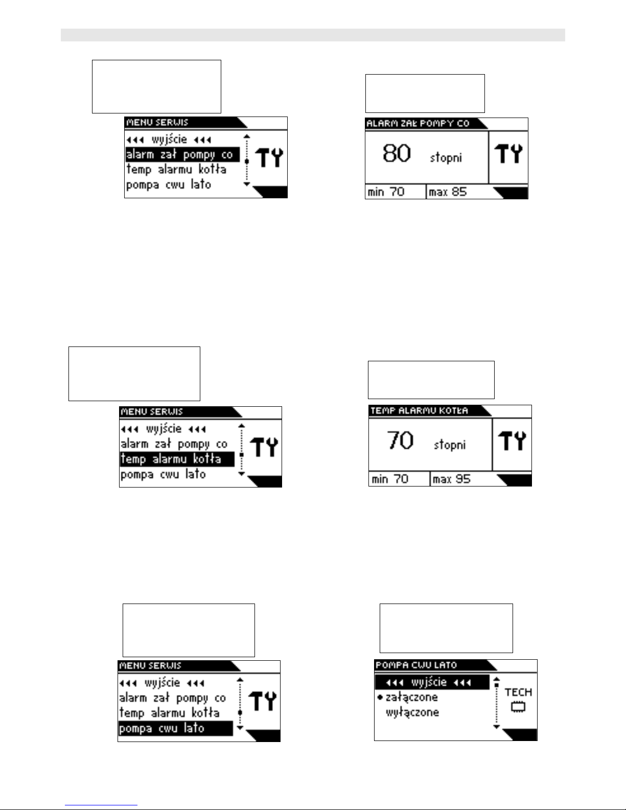
IV.4.C.H. Pump Activation Alarm
With this function, you can set the alarm temperature for central heating
pump activation. The central heating pump is to be activated in case the
boiler should be overheated, in the water heater priority mode. The
pump runs until the boiler temperature drops by 2°C. This protection is
applied when burnout functions are improperly set.
IV.5.Boiler Alarm Temperature
With this function, you can set the alarm temperature at which the feeder
and the fan will stop and the central heating pump will be activated in
order to distribute hot consumption water throughout the system.
IV.6.H.C.W. Summer Pump
-21-
SERVICE MENU
Exit
C.H. Pump On Alarm
Boiler Alarm Temp
H.C.W. Pump Summer
C.H. PUMP ON ALARM
degrees
SERVICE MENU
Exit
C.H. Pump On Alarm
Boiler Alarm Temp
H.C.W. Pump Summer
BOILER ALARM TEMP
degrees
SERVICE MENU
Exit
C.H. Pump On Alarm
Boiler Alarm Temp
H.C.W. Pump Summer
H.C.W. PUMP SUMMER
Exit
On
Off
Page 22

ST-45 User's Manual
With this function, you can switch on and off the hot consumption water
pump in the summer mode, i.e. specify whether the hot consumption
water pump is to run after the preset temperature has been reached or it
is to be shut off. If you enable the function, the hot consumption water
pump will run permanently in the summer mode, whereas if you disable
it, the pump will be shut off after the preset temperature has been
reached and activated again, depending on the boiler hysteresis applied.
IV.7.C.H. Pump Room Regulator
With this function, you can switch on or off the central heating pump
when the room regulator is active, i.e. you can decide whether the
central heating pump is to be shut off after the desired room temperature
has been reached.
B) Reed Relay Protection
With this function, you can set the duration of a complete feed cycle. If
the cycle is not completed within the set period, the following message is
displayed: Clean Feeder. In this function, data are obtained form the Hall
sensor that is located at the feeder.
V.Stand-by Mode
-22-
SERVICE MENU
Exit
C.H. Pump Room Reg.
C.H. PUMP ROOM REG.
Exit
On
Off
MENU
Exit
Service Menu
Stand-by Mode
Page 23

TECH
In this function, you can switch on or off the stand-by mode for the
thermoregulator. All motors of devices (e.g. fan) that are connected to
the thermoregulator are stopped.
ATTENTION: in the stand-by mode, the power is not cut off
completely.
Alternatively, you can switch the controller into the stand-by mode by
pressing and holding the encoder for several seconds.
VI.Protections
In order to ensure a safe and faultless operation, the regulator has
been provided with numerous protections. In the case of an alarm, an
acoustic warning is sounded and the display shows an appropriate
message.
Press the encoder to restore the controller to operation.
VI.1.Temperature Alarm
The protection is enabled only in the duty mode (i.e. when the
furnace temperature is lower than the setpoint temperature). When the
furnace temperature fails to rise in the user-defined period, an alarm is
activated: the feeder and the fan are shut off (the water pump is
activated regardless of the furnace temperature) and the alarm is
sounded. The display shows an appropriate message:
If you press the encoder, the regulator will deactivate the alarm.
The regulator will return to the previous working mode.
VI.2.Thermal Protection
The boiler is protected with an additional bimetal sensor (located at
the furnace sensor) that deactivates fan and feeder outputs when the
-23-
Page 24

ST-45 User's Manual
temperature exceeds the critical value, ranging from 85°C and 90°C. This
is to prevent water from boiling in the system when the boiler has been
overheated or the regulator damaged. With this type of safety
temperature protection, the system will return to the initial position
(automatically).
ATTENTION: in case the thermal relay is damaged, the fan and the
feeder are inoperative in both modes: manual and automatic.
VI.3.Automatic Sensor Check
When the temperature sensor of the central heating, hot
consumption water, screw or grate is damaged, an alarm is activated
with an additional indication shown in the display, e.g.: C.H. Sensor
Damaged:
the feeder and the fan are shut off. The pump is activated
regardless of the actual temperature. If you press the encoder (this
refers to the hot consumption water sensor), the regulator will deactivate
the alarm and the controller will return to its normal operation with a
single pump. If the central heating sensor or feeder sensor is damaged,
the alarm will remain active until the sensor is replaced.
VI.4.Anti-Boil Protection
This function is used for protecting the boiler against high
temperatures [only with the water heater priority function], e.g.
when the water heater setpoint temperature is 55°C and the boiler
temperature is 62°C, the controller shuts off the feeder and the fan.
When the temperature reaches 80°C, the central heating pump is
activated. When the temperature continues to rise, the alarm is sounded
at 85°C. Such condition may appear when the water heater or the pump
are damaged or when the sensor has been improperly mounted.
-24-
Page 25

TECH
However, if the temperature continues to drop, the controller will activate
the feeder and the fan at 60°C and it will continue to operate until the
water heater setpoint temperature is reached.
VI.5.Temperature Protection
The regulator features an additional protection in case the bimetal
sensor is damaged. After the temperature exceeds 95°C, the alarm is
sounded. The display shows: Temperature Too High
The current temperature is read from an electronic sensor and processed
by the thermoregulator. When the alarm temperature is exceeded, the
fan is shut off and both pumps begin to run in order to distribute hot
consumption water throughout the system.
VI.6.Fuel Container Protection
At the fuel container screw, an additional temperature sensor is
mounted. If the temperature rise is high (above 70°C), the alarm is
sounded: the feeder is activated for 3 minutes with the fuel being moved
into the combustion chamber. The screw sensor protects the fuel from
being combusted in the grate.
VI.7.Fuse
The regulator features two WT 6.3A tube fuses to protect the
network.
ATTENTION: it is not advisable to use fuses with higher current ratings.
Higher current ratings may cause damage to the controller.
-25-
Page 26

ST-45 User's Manual
VII.Maintenance
Before and during the heating season, the ST-45 controller should be
checked for any damages in its cables. You should also check if the
controller is properly mounted and clean it if dusty or dirty. It is
advisable to measure grounding parameters for the motors (central
heating pump, hot consumption water pump, fan, feeder, floor pump and
circulation pump).
We are committed to protecting the environment. Manufacturing electronic devices imposes an
obligation of providing for environmentally safe disposal of used electronic components and devices.
Hence, we have been entered into a register kept by the Inspection For Environmental Protection. The
crossed-out bin symbol on a product means that the product may not be disposed of to household
waste containers. Recycling of wastes helps to protect the environment. The user is obliged to transfer
their used equipment to a collection point where all electric and electronic components will be recycled.
-26-
Page 27

TECH
No. Specification Unit
1 Supply Voltage V 230V/50Hz +/-10%
2 Max. Power Consumption W 11
3 Ambient Temperature
O
C
10 - 50
4 Central Heating; Hot Consumption Water;
Floor; Circulation - Pump Outlet Load
A
,0 5
5 Fan Output Load A
,0 6
6 Feeder Output Load A
2
6
7
8
9
10
Temperature Measurement Range
Measurement Accuracy
Temperature Adjustment Range
Sensor Thermal Resistance
Fuse Insert
O
C
O
C
O
C
O
C
A
0 - 85
1
45 - 80
-25 - 100
6,3
VIII.Assembly
ATTENTION: all assembly works must only be carried out by qualified
persons. During assembly, the device must be disconnected (make sure
the power cord is unplugged)!
ATTENTION: improper cable connection may damage the regulator!
ATTENTION: the ST-45 controller must be built into the boiler so that
the cable connection strips are not accessible.
The regulator may not be operated in a closed-circuit central heating
system. It is necessary to provide for safety valves, pressure valves and
a surge tank in order to prevent water from boiling in the central heating
system.
-27-
Page 28

ST-45 User's Manual
VIII.1.Cable Connection Diagram for Controller
Particular attention should be paid when making cable connections with
the controller. Especially, the grounding conductor should be connected
properly.
PE-GROUND (YELLOW-GREEN)
N- NEUTRAL (BLUE)
L- PHASE (BROWN)
-28-
Figure 1: ST-45 cable connection diagram
Page 29

TECH
Table of Contents
I. Description.................................................................................. 4
II. Regulator Functionality................................................................ 5
II.1. Main Page............................................................................. 5
II.2. C.H. Setpoint Temperature.....................................................6
II.3. H.C.W. Setpoint Temperature..................................................6
II.4. Screen................................................................................. 7
II.5. Manual Mode.........................................................................7
II.6. Feed Interval........................................................................ 8
II.7. Blow Force............................................................................9
II.8. Operation Mode.....................................................................9
II.8.a) House Heating.................................................................9
II.8.b) Water Heater Priority.....................................................10
II.8.c) Parallel Pumps..............................................................11
II.8.d) Summer Mode..............................................................11
II.9. Sustain Mode Operation........................................................12
II.10. Pause in Sustain Mode........................................................12
II.11. Sustain Mode of Fan...........................................................12
III. Fitter’s Menu........................................................................... 13
III.1. Factory Settings.................................................................13
III.2. Valves 1 and 2................................................................... 13
III.2.a) Registration.................................................................14
III.2.b) Temperature Monitoring................................................14
III.2.c) Opening Time.............................................................. 15
III.2.d) Single stroke...............................................................15
III.2.e) Minimum opening.........................................................15
III.2.f) Valve Type...................................................................16
III.3. Temperature Alarm............................................................. 16
III.4. Room Regulator..................................................................16
III.5. Boiler Hysteresis.................................................................17
III.6. H.C.W. Hysteresis...............................................................17
III.7. Floor Heating Pump.............................................................18
III.8. Circulation Pump................................................................18
III.9. Automatic Mode of Feeder....................................................19
III.10. Language Version.............................................................19
III.11. Software Version...............................................................19
IV. Service Menu........................................................................... 20
IV.1. Pump Switch-on Temperature...............................................20
IV.2. Feeder Alarm Temperature...................................................20
IV.3. Priority Temperature............................................................21
IV.4. C.H. Pump Activation Alarm..................................................21
-29-
Page 30

ST-45 User's Manual
IV.5. Boiler Alarm Temperature....................................................22
IV.6. H.C.W. Summer Pump......................................................... 22
IV.7. C.H. Pump Room Regulator..................................................22
B) Reed Relay Protection............................................................. 23
V. Stand-by Mode..........................................................................23
VI. Protections..............................................................................24
VI.1. Temperature Alarm............................................................. 24
VI.2. Thermal Protection..............................................................24
VI.3. Automatic Sensor Check......................................................25
VI.4. Anti-Boil Protection.............................................................. 25
VI.5. Temperature Protection........................................................25
VI.6. Fuel Container Protection.....................................................26
A) Fuel Container Protection (Hall Sensor).....................................26
VI.7. Fuse..................................................................................26
VII. Maintenance........................................................................... 27
VIII. Assembly.............................................................................. 28
VIII.1. Cable Connection Diagram for Controller..............................29
-30-
Page 31

TECH
-31-
Page 32

ST-45 User's Manual
-32-
 Loading...