

Page 1

Tech
- 1 -
Page 2

ST-408 – user's manual
Declaration of Conformity No. 44/2011
Hereby, we declare under sole responsibility that the
ST-402 230V 50Hz thermoregulator manufactured by TECH,
headquartered in Wieprz 1047A, 34-122 Wieprz, is compliant
with the Regulation by the Ministry of Economy. (Journal of
Laws Dz.U. 155 Item 1089) of July 21, 2007 implementing
provisions of the Low Voltage Directive (LVD) 2006/95/EC of
January 16, 2007.
The ST-402 controller has been tested for electromagnetic
compatibility (EMC) with optimal loads applied.
For compliance assessment, harmonized standards were
used: PN-EN 60730-2-9:2006.
- 2 -
Page 3

Tech
ATTENTION!
High voltage!
Make sure the regulator is disconnected from
the mains before working on the power
supply (cable connections, device
installation, etc.)!
All connection works must only be carried
out by qualified electricians.
Before activating the controller, measure the
motor resetting efficiency and inspect wire
insulation.
- 3 -
Page 4

ST-408 – user's manual
- 4 -
Page 5
Tech
I. Application
ST-408 type thermoregulator is intended for the operation of central
heating system installation. The controller supports two mixing valves
and HUW pump (boiler pump). Optionally, controller may co-operate
with two ST-61 modules, which allows to control four mixing valves
altogether. The controller is equipped with weather control function,
weekly program, and may cooperate with two room two-state
regulators (standard) and with one TECH regulator.
An additional advantage of the device is the protection of return
temperature, which fulfills the function of protection against boiling of
the water in the short furnace circulation or against too low temperature
of the water returning to the water furnace.
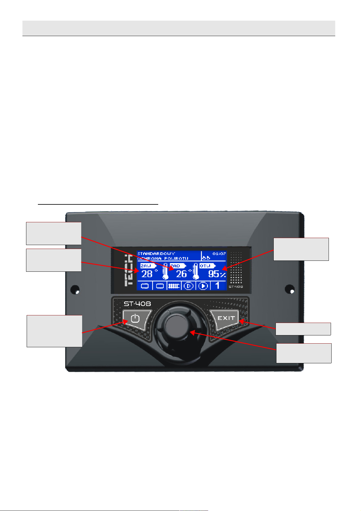
II. Principle of operation
Description of control panel
Operational principle of installation controller is based on mixing the
supplying circulating warm water, with the water, which comes back from
heating circulation, in order to set the desired temperature and maintaining it
all the time at the same level.
The pump is connected to the cycle of each valve, and is supposed to help
water distribution in the system. The pump should be installed behind the
mixing valve, while the temperature sensor should be placed behind the valve
and the pump, for the purpose of the most accurate control of temperature at
valve outlet.
- 5 -
PRESET
TEMPERATURE
OPENING
TEMPERATURE
BEHIND VALVE
STANDBY
MODE
(STANDBY)
PERCENTAGE
EXIT
PULSE
GENERATOR
Page 6
ST-408 – user's manual
ATTENTION: if the valve controller operates, at the same time, in a
circulation common with the furnace controller, the pump can be connected
from the furnace controller (the outlet of such pumps from ST-408 type
regulator or from an additional module will remain disconnected).
The control takes place with the use of pulse generator knob. Entering
MENU and settings confirmation proceeds by pressing the knob. When turning
it, a user operates in MENU functions. To go to the higher level menu, use exit
button. Any settings may be changed in a similar manner.
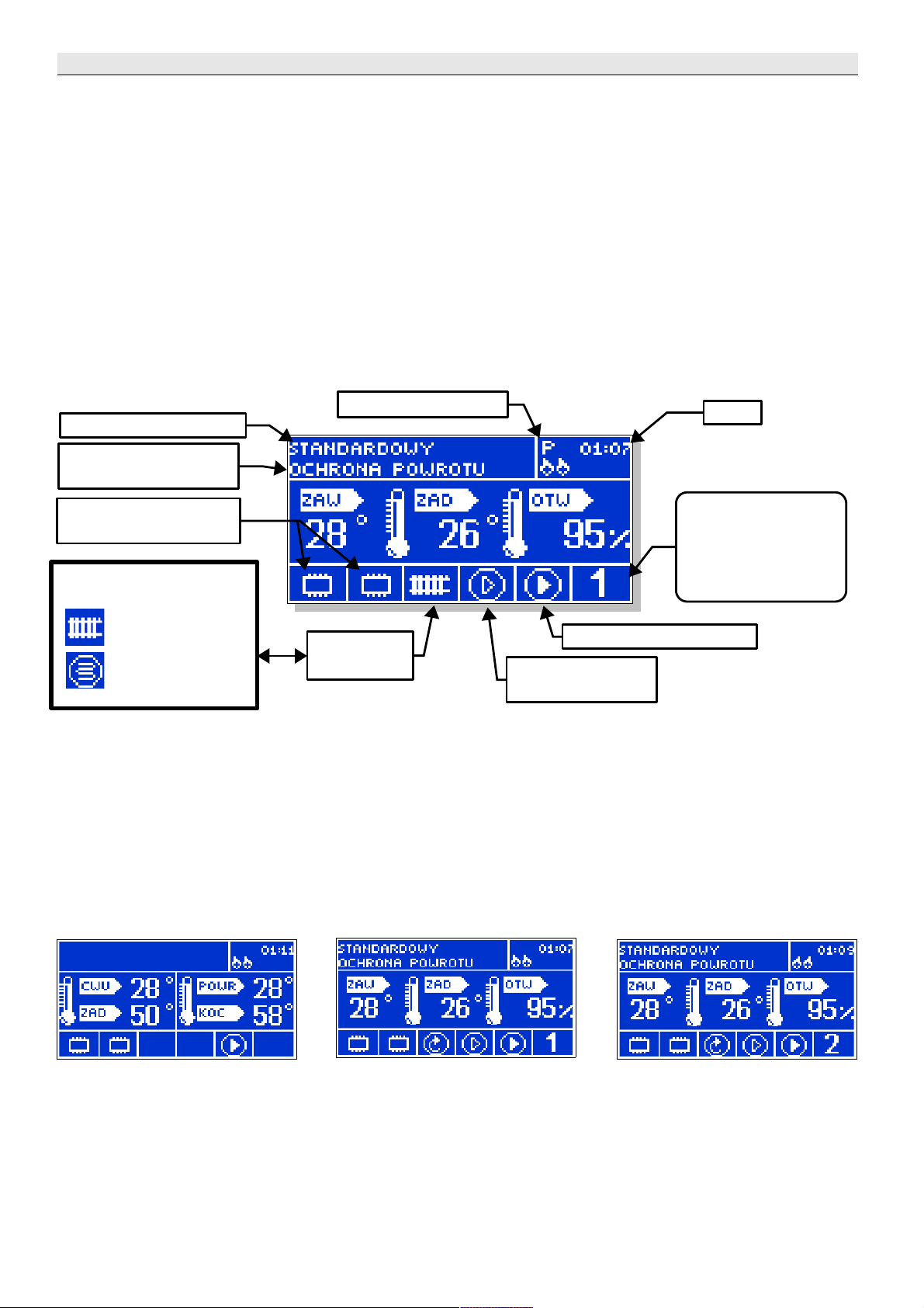
II.a) Main page
During normal regulator operation , graphic display shows the
homepage, on which the following are displayed:
Valve type:
- C.H.
- FLOOR
By turning the pulse generator, the preset temperature can be easily
changed (the change is set for the currently visible main screen). After
pressing pulse generator knob, the user moves to the main menu.
To change homepage appearance for the boiler temperature view,
another valve or one of the additional valves (if active), EXIT key should be
pressed. Then, after choosing another screen, homepage view is changed.
- 6 -
ACTIVE MODULES
ADDITIONAL
OPERATION MODE
VALVE PUMP
WORK
BOILER
PROTECTION
HOUR
ACTIVE
VALVE
HUW PUMP WORK
NUMBER OF THE
VALVE, THE
PARAMETERS OF
WHICH ARE
VISIBLE
ROOM CONTROL
Page 7
Tech
III. Main menu
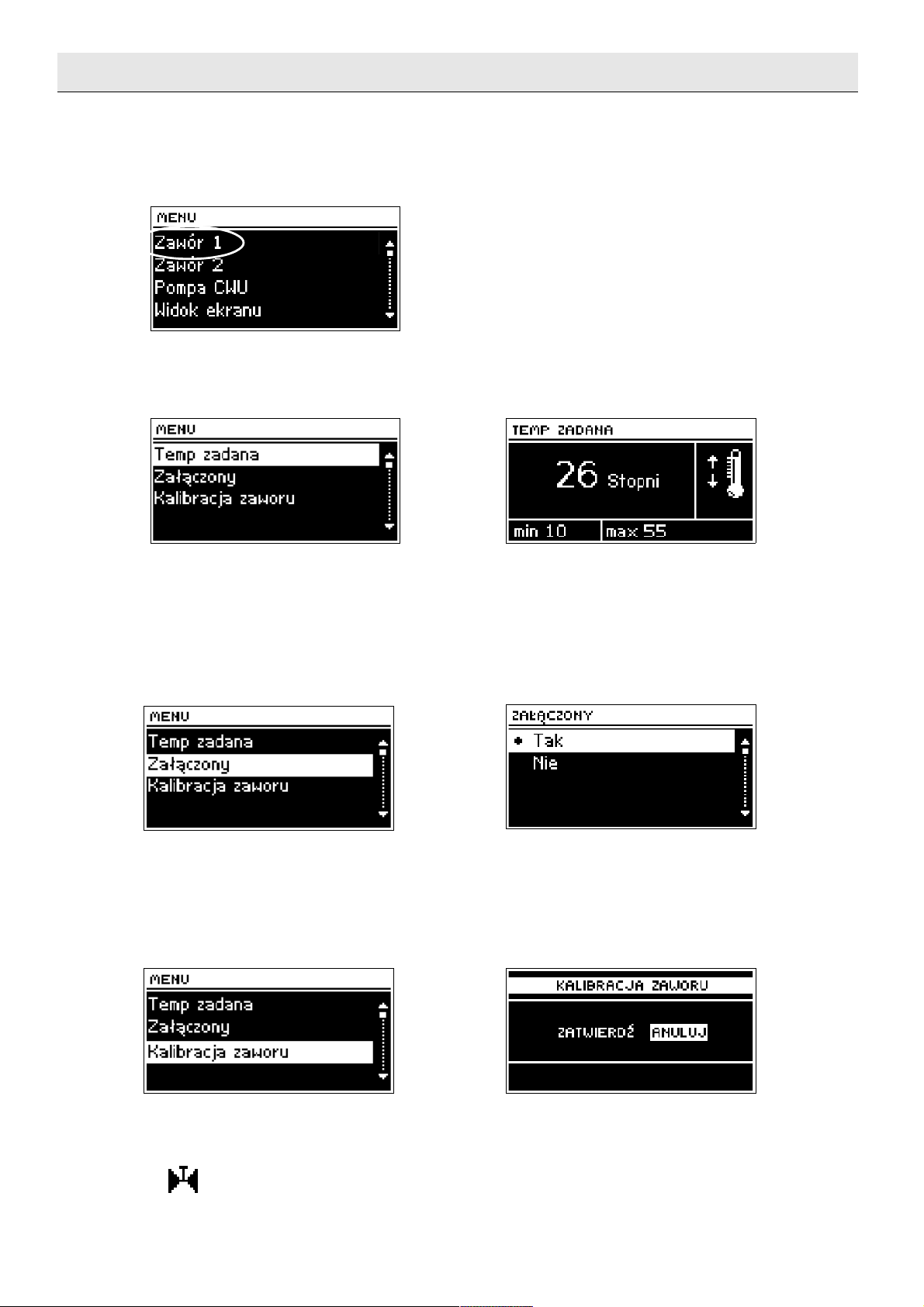
III.a) VALVE 1
In this submenu, a user sets the basic parameters of the first valve.
III.a.1) Preset temperature
With this option, the requested temperature is set, and VALVE 1 is
supposed to maintain it. The temperature can be also changed directly from
the controller main screen when Temp 1 view is active. In the course of
correct operation, water temperature behind the valve will be approaching the
preset valve value.
III.a.2) Activated
This option is used to activate valve 1. When valve is deactivated, the
pump is also deactivated. In spite of the fact that valve is deactivated,
calibration always takes place after switching the controller to the network. It
prevents from remaining valve in a dangerous position.
III.a.3) Valve calibration
Using this function, valve 1 can be calibrated at any time. During
calibration, valve is set to a safe position, that is, for CH valve, to a fully open
position, while for floor valve, to a closed position. When calibration is in
progress, the following symbol is displayed at the bottom of the main
screen:.
- 7 -
Page 8

ST-408 – user's manual
III.b) Valve 2
In this submenu, a user sets the basic parameters of the first valve, the same
as for valve 1 settings.
III.c) HUW pump (boiler pump)
This function is used to set HUW pump working parameters.
III.c.1) HUW preset temperature
With this function, the preset temperature of utility water is set; The
temperature can be also changed directly from controller main screen, when
HUW view is active. After heating water in the boiler up to this temperature,
the regulator deactivates HUW pump. The pump will be re-activated when the
temperature decreases below the value set by HUW hysteresis parameter
value.
III.c.2) Operational modes
This function allows for a complete deactivation of HUW pump, if it is not
used, or for the activation of automatic operation (then it works according to
the settings included in this chapter).
III.c.3) HUW hysteresis
This option is used to set the hysteresis of the preset boiler temperature.
This is a difference between the preset temperature (that is, the one required
at the boiler) and the temperature of returning to work (for example: when
the preset temperature has the value of 55°C and the hysteresis is 5°C. After
reaching the preset temperature, namely 55°C, HUW pump shuts down. HUW
pump will be re-activated when the temperature decreases to 50°C).
- 8 -
Page 9
Tech
III.c.4) HUW pump activation threshold
This option is used to set HUW pump activation temperature (it is the
temperature measured at the furnace sensor). The pump does not work below
the preset temperature, and above this temperature the pump is activated
and works till achieving the preset temperature.
III.c.5) Weekly regulator (weekly control of HUW pump)
This function is used for programming daily temperature changes of the
boiler. The set temperature deviations are in the range of +/-10 0C.
Operation of the weekly control is described in Chapter IV.c.16.
III.d) Circulation pump
This function is used to control the pump mixing hot water between the
furnace and the hot utility water receivers. The User, after activation of this
function, sets the daily cycle of activation or standstill of the pump with the
accuracy of 30 minutes.
To facilitate setting the daily cycle of operation and standstill of the
pump, there is a possibility to copy the selected time interval to further ones.
After setting the operation plan, it is required to set operation time and
standstill time of the pump, while the time interval selected before is active.
When necessary, it is possible to quickly remove earlier settings to facilitate
setting of new intervals.
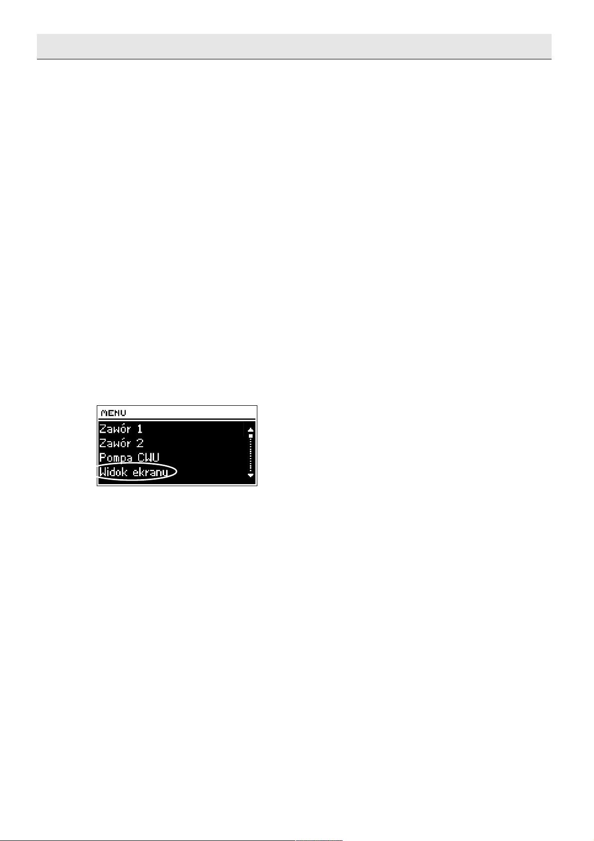
III.e) Screen view
Using this function, homepage appearance may be changed between the
views of : basic valves, temperatures of furnace sensors, boiler temperatures
or parameters of one of the additional valves (only when the valves are
active).
After choosing the Valve screen view (1 or 2) on the website, the
following temperatures will be displayed on the homepage: valve temperature
(preset and current value) and opening percentage.
Temp 1 or Temp 2 view selection causes the display of the parameters
of the chosen valve on the homepage: the preset and the current
temperatures, external and return temperatures.
HUW view selection causes the display of the temperatures of the boiler
on the homepage: the preset and the current, external temperature and the
furnace temperature.
Additionally, after installing the additional valves, the views with their
parameters are available: the parameters of the preset and the current
temperatures, external and return temperatures, and the opening percentage
(deviation) of the chosen valve.
Screen view selection menu may be entered by pressing EXIT button,
when the main screen view is active.
- 9 -
Page 10

ST-408 – user's manual
III.f) Operational Modes
In this function, as necessary, the user activates one mode from three
installation working modes.
III.f.1) Boiler priority
In this mode, firstly, the boiler pump (HUW) is activated until reaching
HUW preset temperature (valves close maximally and valve pumps are
deactivated), after reaching it, the pump is deactivated and mixing valves are
activated (together with pumps – according to their settings).
Valves work constantly, until the moment the boiler temperature drops
below the preset value by hysteresis value. Then, valve pumps are
deactivated and HUW pump is activated.
III.f.2) Paralel pumps
In this mode, all active pump and valves work at the same time. Valves
maintain the preset temperature, and the boiler is heated up to the preset
temperature
III.f.3) Summer mode
Regulator In this mode CH valves close, so as not to heat house
unnecessarily, but in the case of achieving, too high furnace temperature
(requires the activation of the return protection!), emergency valve will be
opened.
In this mode, the boiler pump and floor valves work normally according
to their settings.
III.g) Manual operation
After selecting the option of Manual operation, the user has the
possibility of manually opening/ closing the valves (and the additional valves
when they are active) and switching each HUW and valve pump on or off for
the purpose of inspection of the correct operation of the device.
- 10 -
Page 11

Tech
III.h) Installer menu
Functions included in installer menu will be described in detail in
subsequent chapters of this manual.
III.i) Language selection
A user can select the language version of the controller.
III.j) Factory settings
The regulator is pre-configured for operation. However, it should be
adjusted for own needs. Return to the factory settings is possible at any
moment. By activating the factory settings option, all own adjustments are
replaced by the settings saved by the manufacturer. From that moment, the
own parameters may be set once again.
III.k) About program
After activating this option, the display shows the furnace
manufacturer's logo along with software version of the regulator.
- 11 -
Page 12

ST-408 – user's manual
IV. Installer menu
IV.a) Pump anti-stop
After activating this option, pump valve will activate every 10 days for
2 minutes. It prevents too long water stagnation in the assembly beyond the
heating season.
IV.b) Furnace sensor
In this submenu, the user determines basic furnace protection parameters
and pump activation.
IV.b.1) Return protection
This function permits setting the furnace protection against too cool
water returning from the main circulation, which could cause low-temperature
furnace corrosion. The return protection operates in the way that when the
temperature is too low, valve is closed, until the short circulation of the
furnace reaches the appropriate temperature. After activating it, user presets
the minimum acceptable return temperature.
IV.b.2) Furnace protection
The protection against too high return temperature serves to prevent
the hazardous growth in furnace temperature. The user sets the maximum
acceptable return temperature. In the case of the hazardous growth in
temperature, the valve begins to open to house installation in order to cool
the furnace down. This function is activated permanently (the possibility of
deactivation only in the service menu).
- 12 -
Page 13

Tech
IV.c) TECH room regulator
This option allows to activate/disable the activity of TECH room
regulator. To cooperate with an applicable valve, this type of "room
regulator", should be additionally activated, together with the applicable
operation mode, in a relevant valve menu.
TECH regulator is equipped with RS communication and is connected to
the controller with a four-core communication wire (RJ type – "telephone"
plugs). ST-408 controller may serve only for one TECH room regulator (it can
be additionally connected to two standard regulators).
If TECH room regulator is activated, a user, apart from room control,
has the possibility to change: the preset temperatures of active valves, the
furnace temperature directly from room regulator, without the need to go
down to the furnace room. Additional advantages of the device are: the
access to the history of temperatures in the form of clear charts, light
signaling of all assembly controller alarms, external temperature monitoring
(in cooperation with ST-61 valve module), possibility of setting the weekly
program, etc.
IV.d) Voltage-free contact
The controller may cooperate with any external device activated on the
basis of contact/opening. Output of the voltage-free contact is controlled with
the use of:
- room regulator (when the room regulator does not reach the set value – the
contact is closed, after reaching the set value, the contact opens).
- weekly control (the user sets time intervals with the accuracy to 30 minutes,
in marked intervals, the contact will close).
IV.e) Valve 1
With the use of functions contained in this submenu, the changes are
made in the settings of any parameters of valve 1, in such a way that it works
correctly and in accordance with user expectation.
- 13 -
Page 14

ST-408 – user's manual
IV.e.1) Temperature control
This parameter determines water temperature measurement (control)
frequency behind the CH or HUT installation valve. If the sensor indicates a
change in temperature (deviation from the set value), then the electric valve
will open or close by the set stroke, in order to return to the preset
temperature..
IV.e.2) Opening time
Parameter specifying the time needed for the servomotor valve to open
from 0% to 100% position. This time should be selected according to the
owned valve servomotor (stated on the rating plate).
IV.e.3) Single stroke
This is a maximum single stroke (opening or closing) that the valve may
make during one temperature sampling. If it is near the preset temperature,
the stroke calculated on the basis of WSP PROPORCJON parameter position.
The smaller the single stroke, the more precisely the set temperature can be
achieved. However, the preset temperature is being fixed for a longer time.
IV.e.4) Minimum opening
The parameter determines, which valve opening may be the smallest
Thanks to that parameter, the valve may be opened minimally, to maintain
the smallest flow.
- 14 -
Page 15

Tech
IV.e.5) Valve type
By means of this setting, the user selects the type of the controlled
valve between:
CH - it is set to adjust CH circulation temperature.
FLOOR - it is set to adjust floor heating circulation temperature. Floor type
protects the installation from dangerous temperatures. If the valve type is set
as CH and it will be connected to floor system, this may result in the
destruction of fragile floor installation.
IV.e.6) Room regulator
In this function, the user has the possibility to select the type of room regulator,
which will be assigned to valve 1:
➔ TECH regulator
After selecting this type of "room regulator", valve will work according to <change in
the preset valve temperature> and <difference of room temperatures parameters
(see chapter IV.c.8 and 9). This regulator should be connected to RJ (telephone)
sockets of ST-408 controller by means of a four - core wire ended with the
appropriate plugs (to the socket at the back of the controller).
➔ Standard 1 regulator
After selecting such (two-state) regulator, the valve will work according to <room
regulator reduction parameter (see chapter IV.c.10). The connection of such "room
regulator" should be performed to the place described at the controller: Room
regulator 1 with the use of two-core wire.
➔ Standard 2 regulator
After selecting such (two-state) regulator, the valve will work according to <room
regulator reduction parameter. The connection of such "room regulator" should be
made to the place described at the controller: Room regulator 2 with the use of two-
core wire.
Communication plug for TECH regulator (at the back of the controller)
- 15 -
Page 16
ST-408 – user's manual
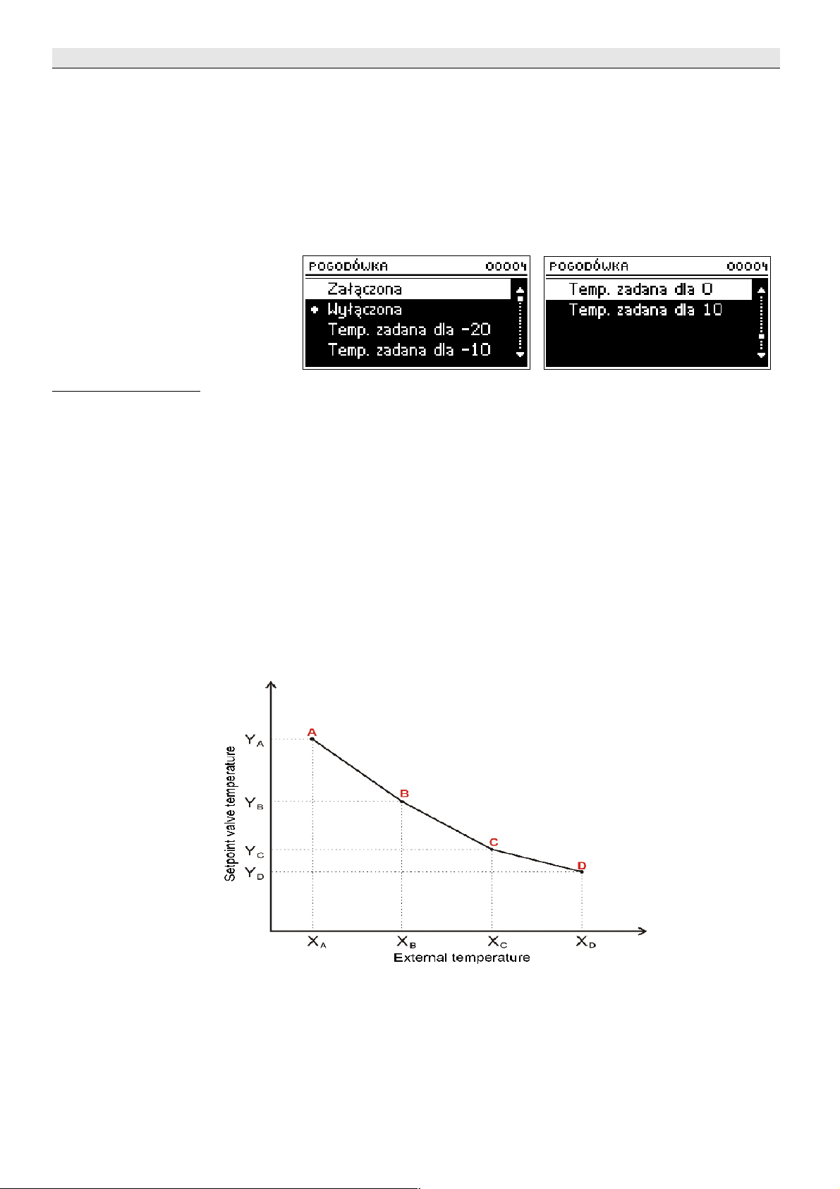
IV.e.7) Weather sensor (weather-based control)
To activate the weather function, external sensor should be placed in the
place which is not insolated and not exposed to atmospheric impacts. After
installation and connection, a sensor should have the function Weather sensor
activated in a controller menu.
To make sure that the valve works correctly, the set temperature is set
(behind the valve) for four intermediate external temperatures:
TEMP. FOR -20
TEMP. FOR -10
TEMP. FOR 0
TEMP. FOR 10
Heating curve – this is a curve, according to which the preset controller
temperature is determined, on the basis of external temperature. In our
controller, this curve is constructed on the basis of three points of set
temperatures for the respective external temperatures. The preset
temperatures must be determined for external temperatures - 20ºC, -10ºC,
0ºC and 10ºC.
The more points constructing the curve, the greater its accuracy, which
allows its flexible shaping. In our case, four points seem to be a very good
compromise between the accuracy and the ease in setting the course of this
curve.
Where, in our controller:
XA = -20ºC, XC = 0ºC,
XB = -10ºC, XD = 10ºC,
YA, YB, YC, YD – preset valve temperatures for respective external
temperatures: XA, XB, XC, X
D
After activating the weather control, preset valve temperature
parameter is not available
- 16 -
Page 17
Tech
IV.e.8) Change in the preset valve temperature
This setting determines by how much degrees the temperature will
increase or decrease at the single room temperature change (see: difference
in room temperatures). This function is active only with the TECH room
regulator and is strictly related to difference in room temperatures parameter.
IV.e.9) Difference in room temperatures
This setting determines a single change in the current temperature
(down to 0,1
with
C) at which the determined temperature change will take
place in the preset valve temperature (the function is active only with the
TECH room regulator).
Example:
setting: Difference in room temperatures 0,5ºC
setting: Change in preset valve temperature 1ºC
setting: Preset valve temperature 40ºC
setting: Preset room regulator temperature 23ºC
Case 1. If the room temperature increases up to 23,5ºC (by 0,5ºC), the valve
will close to the preset 39ºC (by 1ºC).
Case 2. If the room temperature drops to 22ºC (by 1ºC), the valve opens to
the preset 42ºC (by 2ºC).
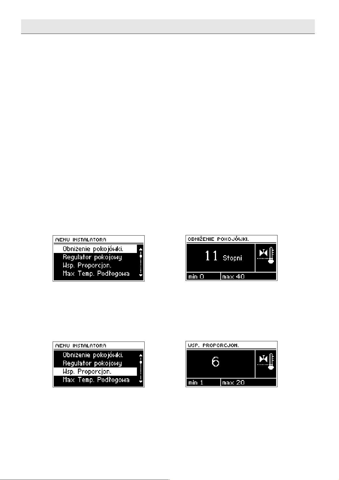
IV.e.10) Room regulator reduction
This function is active only in the event when the valve cooperates
with the two-state room (standard) regulator. In this setting, one should
preset the temperature by which the valve decreases its preset temperature,
at the moment of achieving the preset temperature at the room regulator
(room heat-up).
IV.e.11) Proportionality coefficient
Proportionality coefficient is used for defining valve stroke. The closer
the preset temperature, the smaller the stroke. If this coefficient is high, the
valve will faster achieve the opening close to the relevant. However, the
opening will not be accurate. Single opening percentage is calculated on the
basis of a formula:
(SET_TEMP - SENSOR_TEMP) * (PROP_COEFF /10)
- 17 -
Page 18

ST-408 – user's manual
IV.e.12) Maximum floor temperature
This is the maximum temperature, which does not damage floor
installation. Setting this temperature is used, when valve type is set as the
floor type. After reaching this temperature, a complete valve closure takes
place, and a user is informed about that by means of a relevant alarm. If the
maximum floor temperature is reached, the furnace protection function is
deactivated. In this case, the floor installation protection will have a higher
priority.
IV.e.13) Opening direction
If after connection of the valve to the controller it turns out that it was
to be connected the other way round, then the power supply cables do not
have to be switched, it is enough change the opening direction in this
parameter.
LEFT *
RIGHT *
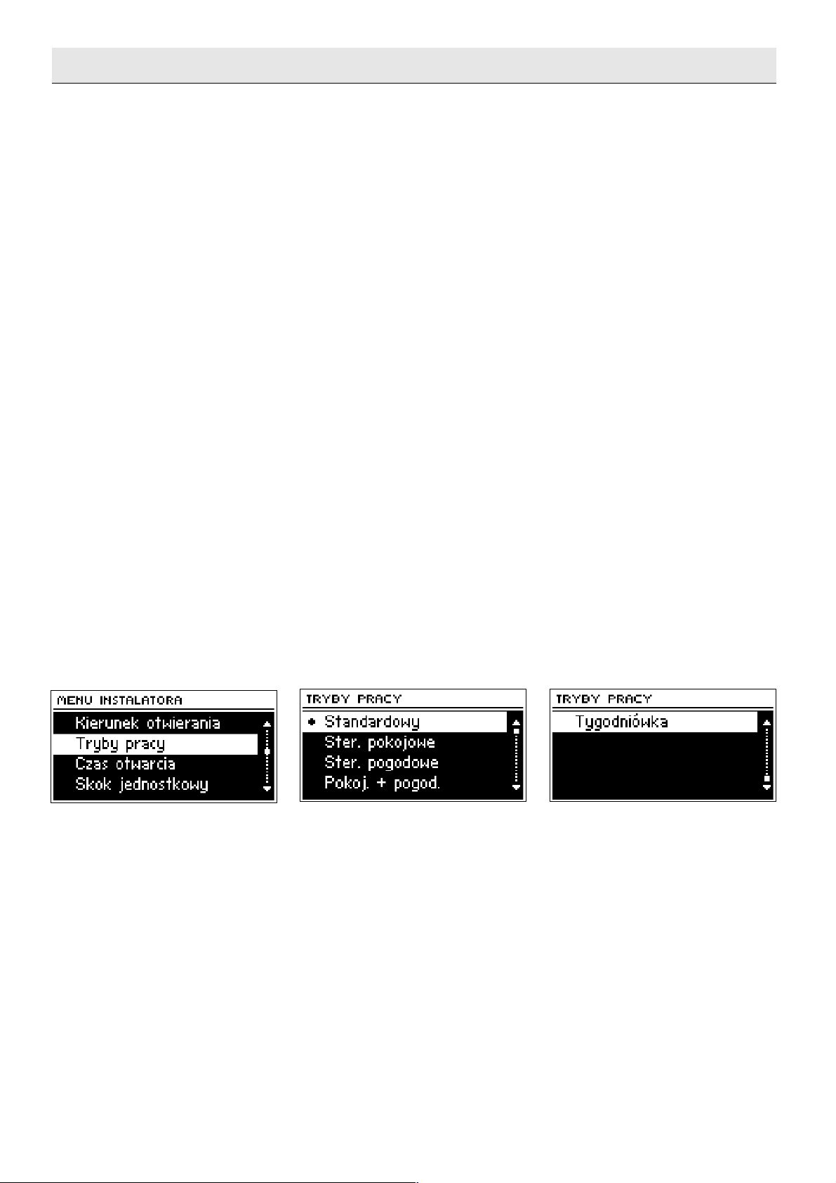
IV.e.14) Operational modes
In this function, user selects the working mode between:
STANDARD - the controller maintains the preset temperature at the valve
exit level.
ROOM CONTROL – in the event of standard (two-state) application of room
regulator, the controller maintains the preset valve temperature till the
- 18 -
Page 19
Tech
moment in which room regulator gives the signal of room heat-up (contact
divergence). Then the preset temperature shall be reduced by the
temperature value set up according to room regulator reduction parameter
(see chapter: IV.c.10). The reduced preset temperature will not be displayed
on the controller main screen. The information that the room regulator
indicated that the room is heated up is signaled by room regulator
symbol<p>(continuous display, not pulsating).
If TECH type room regulator is used, valve will work all the time
according to <change in the preset valve temperature> and according to
<difference in room temperatures> parameters (see chapter IV.c.8 and 9).
WEATHER CONTROL - the preset valve temperature depends on the
temperature outside. It is calculated on the basis of the functions stipulated in
Weather regulator (see chapter IV.c.7).
ROOM AND WEATHER CONTROL – this mode, in the case of standard (twostate) application of room regulator and when room regulator does not reach
the preset temperature, the valve works just as in weather control. At the
time the room is heated up to the set regulator temperature, the valve starts
to work as in room control mode (temperature decreases by "room regulator
reduction" parameter value). When this mode is active, weather control and
room control symbols pulsate alternately on a display. After reaching the
temperature preset by the controller, the symbol<p>(room regulator heated
up) will be displayed permanently.
If TECH type room regulator is used, valve will work all the time
according to "Weather regulator" calculations, however, the temperature
calculated in such a way will be corrected by the deviation value calculated
according to parameters: according to <change the set valve temperature>
and according to <difference in room temperatures> parameters.
WEEKLY REGULATOR - the preset valve temperature depends on the value
deviations defined for particular weekdays in Chapter Weekly regulator (see
chapter: IV.c.16). Room control or weather control is not active in this mode.
The active weekly control is indicated by the current temperature deviation
value pulsating on the main screen (at the place of"preset text).
IV.e.15) Pump activation
This option allows to select the working mode of a pump. A pump shall
be activated: always (pump works all the time, regardless of temperatures),
never (pump is permanently deactivated and only valve work is controlled by
the regulator), above the threshold (the pump is switched on above the
preset activation temperature ). If pump is to be activated above the
threshold, the threshold temperature of pump activation should be also
preset.
- 19 -
Page 20
ST-408 – user's manual
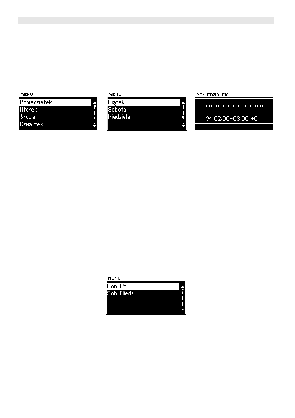
IV.e.16) Weekly regulator (weekly program)
This function is used for programming daily temperature changes behind
the valve. The set temperature deviations are in the range of +/-10
0
C.
Step one:
A user must first set the current time and date (Installer menu> Timer).
Step two:
The user sets temperatures for particular weekdays (Set mode 1):
Monday – Sunday
In this mode, specific hours and the requested deviations from the
preset temperature should be marked (by how many degrees the
temperature is supposed to raise or drop in a given hour) for each day of
the week. Additionally, to facilitate the service, there is a possibility to
copy the settings.
Example
Monday
set: 300 AM, TEMP -100 C (temperature change – 100 C)
set: 400 AM, TEMP -100 C (temperature change – 100 C)
set: 500 AM, TEMP -100 C (temperature change – 100 C)
In this case, if the set valve temperature is 600 C, on Monday from 300 to
600, the preset valve temperature shall drop by 100 C, so it will be 500 C
Instead of setting the temperatures for different days, the temperatures in
the second mode may be set collectively for working days (Monday to Friday)
and weekend (Saturday and Sunday) – Set mode 2.
Monday – Friday; Saturday – Sunday
In this mode, like in the previous one, specific hours and requested
deviations from the set temperature should be marked for business days
(Monday-Friday) and for the weekend (Saturday, Sunday).
Example
Monday-Friday
set: 300 AM, TEMP -100 C (temperature change – 100 C)
set: 400 AM, TEMP -100 C (temperature change – 100 C)
- 20 -
Page 21
Tech
set: 500 AM, TEMP -100 C (temperature change – 100 C)
Saturday-Sunday
set: 4
00
PM, temperature 5 0 C (temperature change + 50 C)
set: 500 PM, temperature 5 0 C (temperature change + 50 C)
set: 600 PM, temperature 5 0 C (temperature change + 50 C)
In this case, if the set valve temperature is 600 C, on Monday from 3
00
until 600, the set valve temperature shall drop by 100 C every weekday
from Monday to Friday, so it will be 500 C. In turn, during weekend
(Saturday, Sunday) from 1600 C to 1900 C, the set valve temperature will
increase by 50 C, so it will be 650 C.
Step three (Mode):
A user activates one of the two previously set modes (Mode1, Mode2),
or deactivates the weekly control option completely.
After activating one of the modes, on the controller homepage, in the place
of preset text (the preset temperature), the digit with the value of the
currently preset deviation shall be pulsating (informing at the same time
about the weekly control activity).
Function delete the data allows to remove the settings of the weekly
program saved before in a simple way, to be able to enter the new settings.
IV.f) Valve 2
If the user wants to control the second valve, like in the previous
case, all settings should be configured in the same manner as in the case of
valve 1.
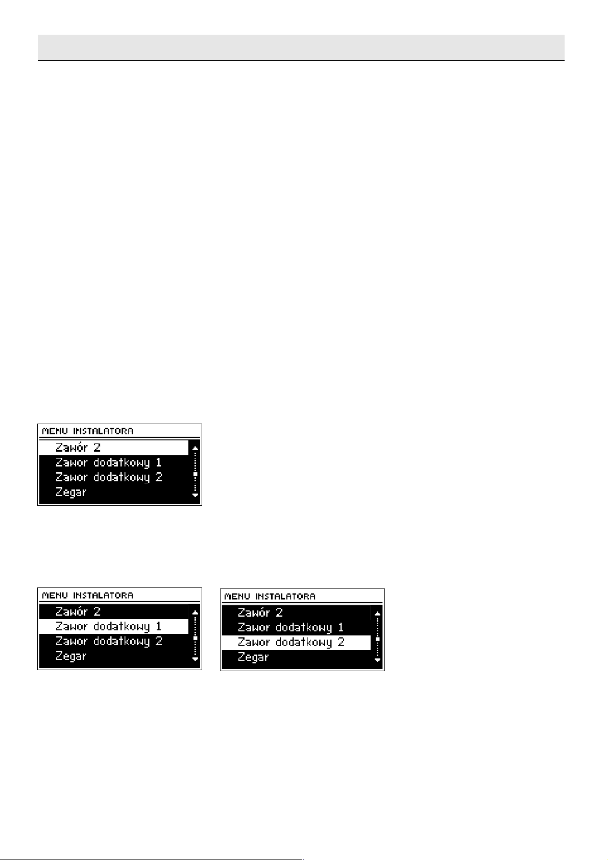
IV.g) Additional valve 1, additional valve 2
The user has the opportunity to control two additional valves (option),
after buying two independent ST-61 modules.
After connection, each additional module should be registered, by
introducing the module number (this number is visible in the casing of module
ST-61). Then, the configuration of an additional valve can be started.
In the case of an additional valve, the following functions should be set:
➢ Activated (switching-on the valve after the finished configuration)
➢ temperature control
- 21 -
Page 22
ST-408 – user's manual
➢ opening time
➢ single stroke
➢ minimum opening
➢ valve type
➢ room regulator
➢ weather sensor
➢ room regulator reduction
➢ return protection
➢ sensors (it should be selected whether the measurement of the furnace
sensor and return sensor is to be read from the main controller –
ST-408 or from ST-61 module output – own sensors)
➢ change in the preset valve temperature
➢ difference in room temperatures
➢ external sensor calibration
➢ factory settings. This parameter allows to return to the settings of a
given valve, saved by the manufacturer. Restoring factory settings does
not change the set valve type (CH or floor)
➢ valve removal. This function is used for a complete removal of a valve
from the controller memory. Valve removal is used e.g. at disassembling
the valve or module replacement (re-registration of a new module is
necessary).
The above parameters that are not described in this chapter in detail are
set identically as described in Chapter Valve 1.
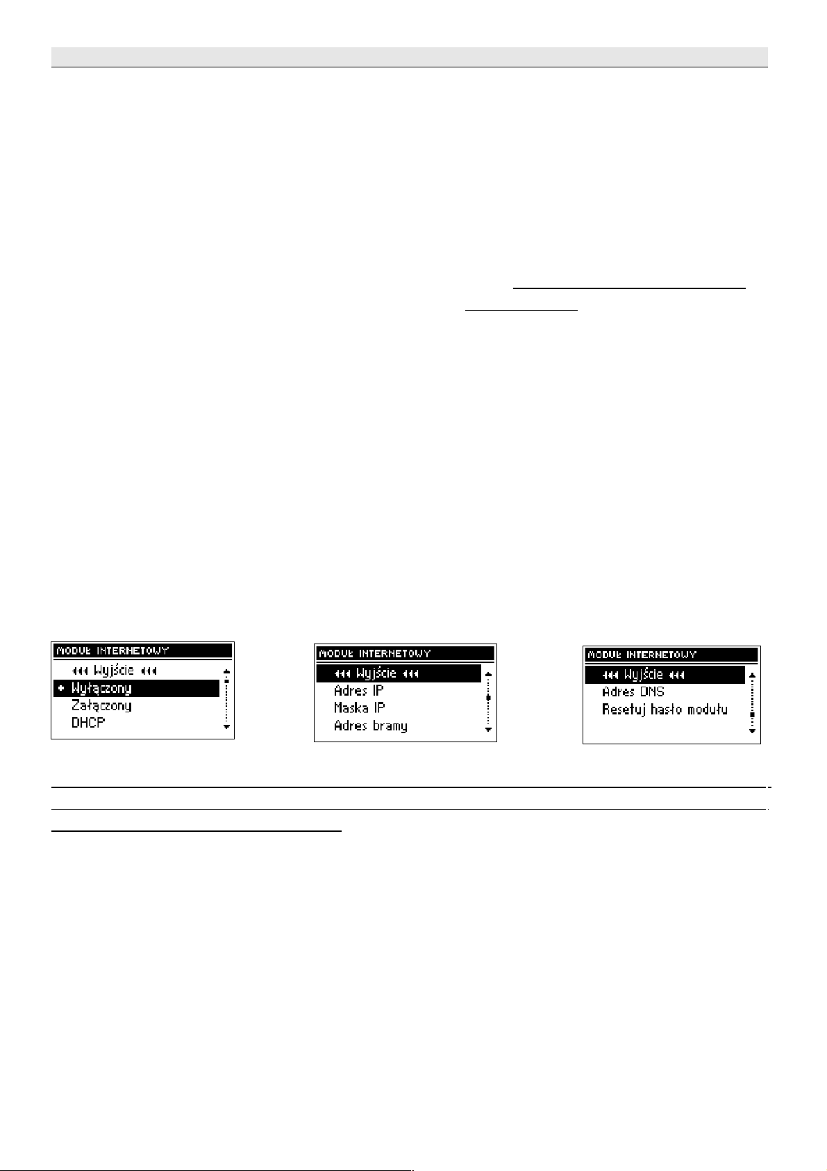
IV.h) Internet module
NOTE
Controlling of this type is possible after purchasing and connecting, to the
controller, the additional control module ST -500 which is not attached to the
regulator as a standard feature.
The Internet module is a device enabling remote control of the boiler
over the Internet or local network . On the home computer screen the user
controls the condition of all boiler system devices and the operation of each
device is presented in the animated form.
Apart from the possibility to view the temperature of every sensor, the
user has the possibility of introducing changes of the set temperatures for
both the pumps and the mixing valves.
After activating the Internet module and selecting the DHCP option, the
controller will automatically download such parameters from the local network
as: IP address, IP Mask, Gateway address and DNS Address. In the case of
any problems with downloading network parameters of the existing network,
there is a possibility of setting these parameters manually. The method of
- 22 -
Page 23
Tech
obtaining local network parameters has been described in the instructions for
the Internet module.
The function Reset module password may be used when the User, on
the login page, has changed the factory user's password to his or her
password. When a new password is lost, it is possible to return to the factory
password after resetting the module password.
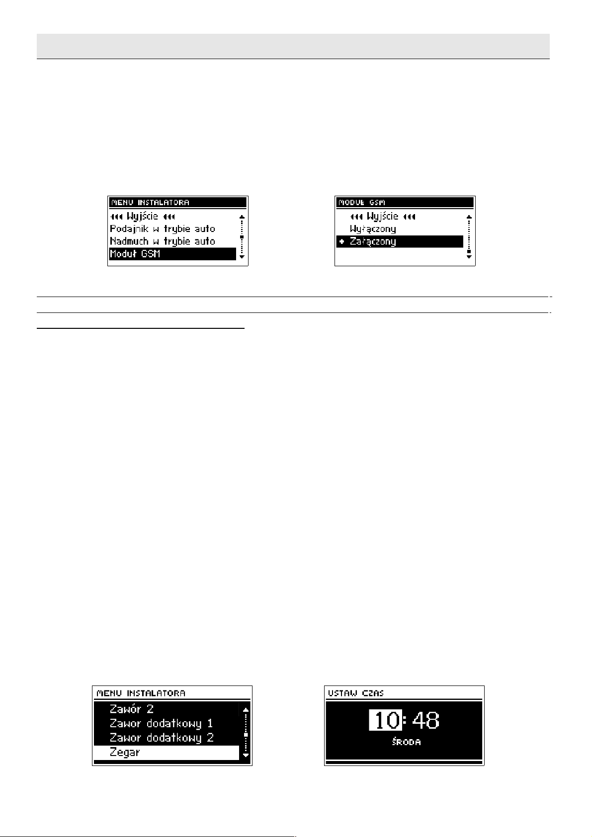
IV.i) GSM module
NOTE
Controlling of this type is possible after purchasing and connecting, to the
controller, the additional control module ST-65 which is not attached to the
regulator as a standard feature.
The GSM module is an optional device cooperating with the boiler
controller, enabling remote control of the boiler operation with the use of a
mobile phone. The User is notified with a text message on each alert of the
boiler controller, and by sending an appropriate text message at any time, he
or she receives a return message with the information on the current
temperature of all sensors. After entering an authentication code it is also
possible to remotely change the set temperatures.
The GSM module can also operate independently from the boiler
controller. It has two inputs with temperature sensors, single contact input for
use in any configuration (detecting short circuit/opening of contacts) and one
controlled output (e.g. possibility to connect additional contactor to control
any electrical circuit).
When any temperature sensor reaches the preset deactivation
temperature, maximum or minimum, the module will automatically send a
text message with such information. It is similar in the case of a short-circuit
or opening of contact input, which may be used e.g. for simple protection of
property.
If ST-408 controller is equipped with an additional GSM module, in order
to activate this device, it is required to start the activated option (MENU>
Installer menu> GSM module> Activated).
IV.j) Timer
By setting the timer, a user defines the current time and weekday. Without
- 23 -
Page 24

ST-408 – user's manual
setting the time, correct operation of the weekly control is not possible.
IV.k) Pulse generator sensitivity
Using this setting, the sensitivity of the pulse generator knob may be
changed in the range between 1 and 3 (where 1 is the highest sensitivity).
IV.l) External temperature measurement
This parameter determines the averaging frequency of the temperatures
during measurement from the external sensor. The measurement is conducted
continuously and every 60 seconds is (factory) averaged and refreshed. The
available range of this setting is within 1 to 600 seconds.
IV.m) External sensor calibration
The external sensor calibration is made during the installation or
after a longer period of use of the regulator, if the external temperature
displayed differs from the actual one. Regulation range: -10 to + 10 OC
with the accuracy to 0.1 OC.
V. Protections
To ensure the maximally safe and reliable operation, the regulator
has several protections. In the case of alarm, a sound signal is activated
and a relevant message is shown on the display.
To make the controller return to work, press pulse generator.
In the alarm, manual work is possible, but it should be completely
ensured whether our activities will not result in damages.
The controller has the following alarm protections:
1. Temperature alarm - stops the valve temperature regulation and sets the
valve in the safest position. For floor valve - it is closing, and for CH valve it is
opening.
2. Alarm - VALVE SENSOR - means an incorrect connection or lack of
connection of the valve sensor or its damage. It is a sensor strategic for valve
operation, therefore it should be replaced immediately.
3. Alarm - RETURN SENSOR – alarm occurs, when the return protection
function is activated and the damage of this sensor takes place. The return
sensor should be then corrected or replaced.
There is a possibility of deactivating this alarm by switching off the return
protection function, but if a circulation does not have the protection against
boiling of water at the furnace, it may cause a permanent damage of the
furnace or a part of circulation.
4. Alarm - WEATHER SENSOR - occurs, when external temperature sensor is
damaged. The alarm may be cancelled, when an undamaged sensor is
installed correctly. The alarm shall be activated, when valve operation mode is
different than "weather control " or "room control with weather control".
- 24 -
Page 25

Tech
The regulator is equipped with WT 1.6A tubular fuse cartridge,
protecting the network.
ATTENTION: The fuse of higher value should not be used. Assembling the
fuse with a higher value may cause damage to the controller.
V. Maintenance
In ST-408 controller, technical condition of wires should be checked
before the heating season and throughout its duration. Fastening of the
controller should be also checked, it should be cleaned from dust and other
dirt.
Technical data
CH valve temperature regulation range 10oC : 90oC
Floor valve temperature regulation range 10oC : 55oC
HUW tank temperature regulation range 1oC : 80oC
Power supply voltage 230V/50Hz +/- 10%
Power consumption max. 4W
Temperature endurance of the sensors -25oC : 90oC
Ambient temperature 5oC : 50oC
Load at each outlet 0,5A
Fuse insert 1,6A
! ATTENTION !
In the case of the lack of flow in short furnace circulation
(installation improperly mounted) the return sensor should be
placed at a warm water outlet from the furnace to prevent the
boiling of water.
VI. Mounting
TTENTION: Installation should be performed by a person with relevant
authorizations! At that time, the device cannot be live (make sure that
the plug is disconnected from the network)!
- 25 -
Page 26

ST-408 – user's manual
Demonstrative installation diagram
- 26 -
Page 27

Tech
Table of contents
I. Application.............................................................................................................................. 5
II. Principle of operation .............................................................................................................. 5
II. a) Main page..................................................................................................................... 6
III. Main menu.............................................................................................................................7
III. a) Valve 1........................................................................................................................ 7
III. a.1) Preset temperature ....................................................................................................7
III. a.2) Activated................................................................................................................... 7
III. a.3) Valve calibration......................................................................................................... 7
III. b) Valve 2........................................................................................................................8
III. c) HUW pump (boiler pump)...............................................................................................8
III. c.1) HUW preset temperature.............................................................................................8
III. c.2) Operational modes...................................................................................................... 8
III. c.3) HUW hysteresis.......................................................................................................... 8
III. c.4) HUW pump activation threshold.................................................................................... 9
III. c.5) Weekly regulator (of HUW pump)..................................................................................9
III. d) Circulation pump...........................................................................................................9
III. d) Screen view.................................................................................................................. 9
III. e) Operational modes.......................................................................................................10
III. e.1) Boiler priority........................................................................................................... 10
III. e.2) Paralel pumps.......................................................................................................... 10
III. e.3) Summer mode..........................................................................................................10
III. f) Manual operation.........................................................................................................10
III. g) Installer menu............................................................................................................11
III. a) Language selection...................................................................................................... 11
III. h) Factory settings........................................................................................................... 11
III. a) About program............................................................................................................11
IV Installer menu.................................................................................................................. 12
IV. a) Pump anti-stop ........................................................................................................... 12
IV. b) Furnace sensor............................................................................................................12
IV. b.1) Return protection................................................................................................... 12
IV. b.2) Furnace protection..................................................................................................12
IV. c) TECH regulator............................................................................................................ 13
IV. c) Voltage-free contact..................................................................................................... 13
IV. c) Valve 1.......................................................................................................................13
IV. c.1) Temperature control ...............................................................................................14
IV. c.2) Opening time.........................................................................................................14
IV. c.3) Single stroke.......................................................................................................... 14
IV. c.4) Minimum opening...................................................................................................14
IV. c.5) Valve type.............................................................................................................15
IV. c.6) Room regulator...................................................................................................... 15
IV. c.7) Weather regulator (weather based control).................................................................16
IV. c.8) Change in the preset valve temperature.....................................................................17
IV. c.9) Difference in room temperatures ..............................................................................17
IV. c.10) Room regulator reduction ...................................................................................... 17
IV. c.11) Proportionality coefficient.......................................................................................17
IV. c.12) Maximum floor temperature ..................................................................................18
IV. c.13) Opening direction.................................................................................................. 18
IV. c.14) Operational modes................................................................................................18
IV. c.15) Pump activation.................................................................................................... 19
IV. c.16) Weekly regulator.................................................................................................. 20
IV. d) Valve 2....................................................................................................................... 21
IV. e) Additional valve 1, Additional valve 2.............................................................................. 21
IV. e) Internet module...........................................................................................................22
IV. e) GSM module................................................................................................................23
IV. f) Timer..........................................................................................................................23
IV. g) Pulse generator sensitivity.............................................................................................24
IV. h) External temperature measurement................................................................................ 24
IV. h) External sensor calibration............................................................................................24
V. Protections.................................................................................................................... 24
VI. Maintenance................................................................................................................. 25
VII. Mounting...................................................................................................................... 25
- 27 -
Page 28

ST-408 – user's manual
- 28 -
 Loading...