

Page 1
EU-2640 user’s manual
1
User’s manual
ST-2640
Page 2

TECH
2
Table of contents
I. Safety ...................................................................................................................... 3
II. Device description .................................................................................................. 4
III. Installing the controller ........................................................................................... 5
IV. Radio communication .............................................................................................. 7
V. First start-up ............................................................................................................ 7
VI. Operating the controller .......................................................................................... 9
VI.a) Principle of operation ............................................................................................ 9
VI.b) View and description of the main screen.................................................................. 9
VII. Controller's functions – Main menu ......................................................................... 10
VII.a) Chart of the controller's menu ............................................................................ 10
VII.b) Manual operation .............................................................................................. 11
VII.c) Channel ........................................................................................................... 11
VII.d) External sensor ................................................................................................. 11
VII.e) Sensors ........................................................................................................... 12
VII.f) Pump ............................................................................................................... 14
VII.g) Language selection ............................................................................................ 14
VII.h) Display contrast ................................................................................................ 14
VII.i) Fitter's menu ..................................................................................................... 14
VII.j) Information on software ..................................................................................... 14
VIII. Protections and alarms ...................................................................................... 15
Fuse ......................................................................................................................... 15
IX. Software update .................................................................................................. 16
X. Technical data......................................................................................................... 16
Page 3

EU-2640 user’s manual
3
I. Safety
Before using the device for the first time the user should read the following regulations carefully.
Not obeying the rules included in this manual may lead to personal injuries or controller damage.
The user’s manual should be stored in a safe place for further reference. In order to avoid
accidents and errors it should be ensured that every person using the device has familiarized
themselves with the principle of operation as well as security functions of the controller. If the
device is to be sold or put in a different place, make sure that the user’s manual is there with the
device so that any potential user has access to essential information about the device.
The manufacturer does not accept responsibility for any injuries or damage resulting from
negligence; therefore, users are obliged to take the necessary safety measures listed in this
manual to protect their lives and property.
WARNING
High voltage! Make sure the regulator is disconnected from the mains before performing
any activities involving the power supply (plugging cables, installing the device etc.)
The device should be installed by a qualified electrician.
Before starting the controller, the user shoud measure earthing resistance of the electric
motors as well as the insulation resistance of the cables.
The regulator should not be operated by children.
WARNING
The device may be damaged if struck by a lightning. Make sure the plug is
disconnected from the power supply during storm.
Any use other than specified by the manufacturer is forbidden.
Before and during the heating season, the controller should be checked for condition of its
cables. The user should also check if the controller is properly mounted and clean it if dusty
or dirty.
We are committed to protecting the environment. Manufacturing
electronic devices imposes an obligation of providing for
environmentally safe disposal of used electronic components and
devices. Hence, we have been entered into a register kept by the
Inspection For Environmental Protection. The crossed-out bin symbol
on a product means that the product may not be disposed of to
household waste containers. Recycling of wastes helps to protect the
environment. The user is obliged to transfer their used equipment to a
collection point where all electric and electronic components will be
recycled.
Page 4
TECH
4
II. Device description
The EU-2640 installation strip is intended to operate the valves both by means of wired and wireless
communication via a radio signal. The strip makes it possible to substantially save the consumption
of electricity due to its precise temperature management of particular rooms in the building. Due
to its expanded software, the regulator may perform a number of functions:
the operation of temperature regulator actuators 230V
one output 230V for the pump
dry contact
the possibility to connect EU-507 Ethernet - makes it possible to control certain functions,
preview certain parameters via the Internet
the possibility to operate battery actuators (wireless) – no more than 9 in a zone
the operation of 8 sensors
the operation of an external sensor
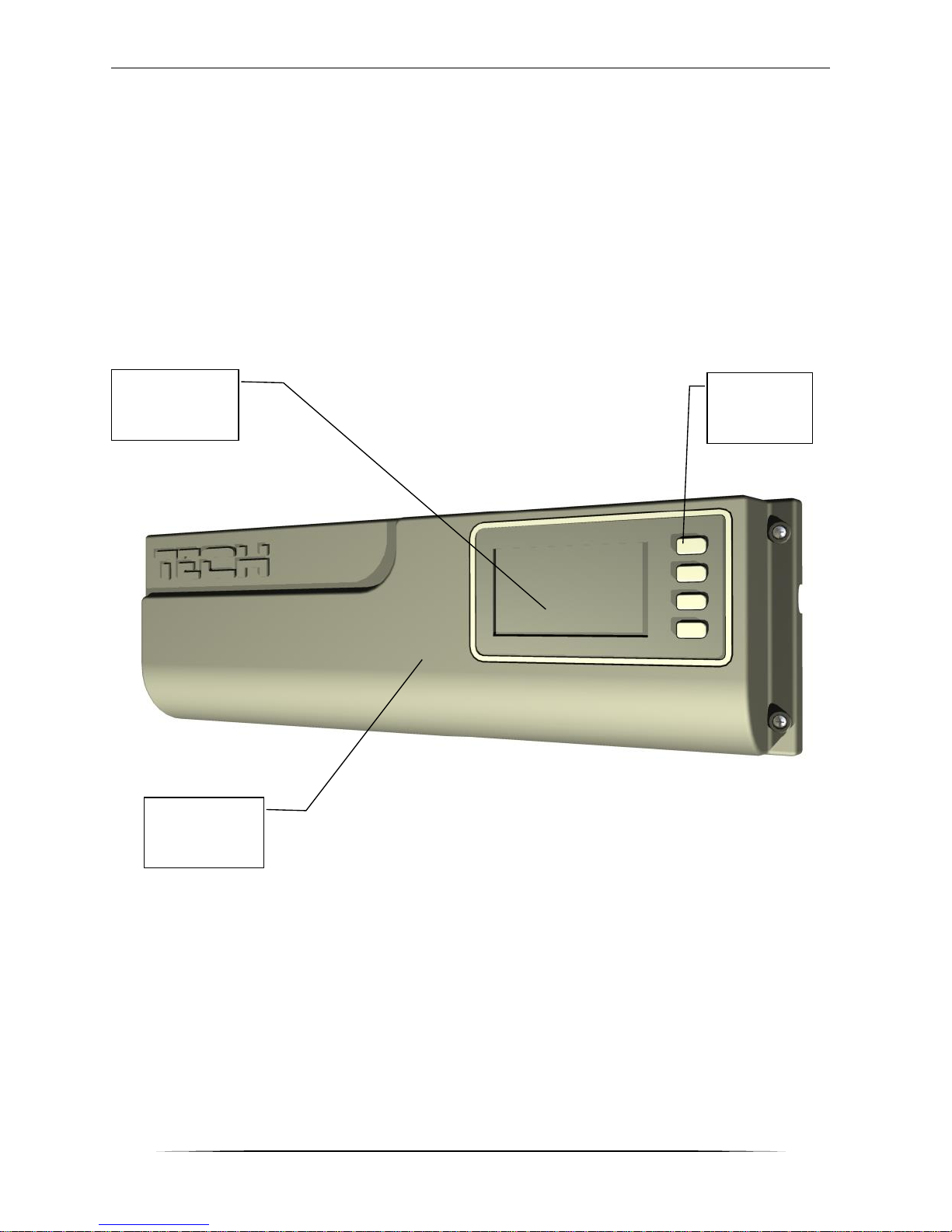
Navigation
buttons
Display
Controller
cover
Page 5
EU-2640 user’s manual
5
III. Installing the controller
The controller should be installed by a qualified person.
WARNING
Risk of fatal electric shock from touching live connections. Before working on the
regulator, switch off the power supply and prevent it from being switched on again.
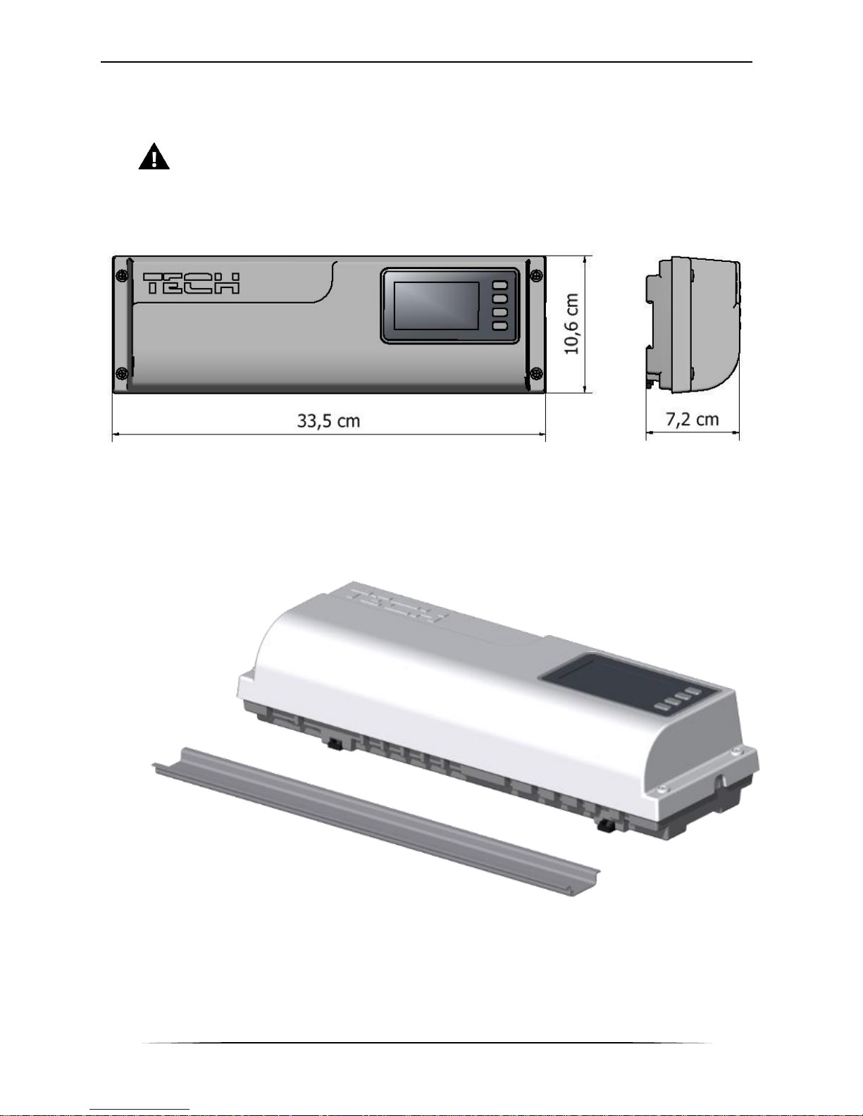
The EU-2640 regulator may be installed as a free-standing device or as a panel mountable on a
wall.
The strip is adapted for installation on a DIN strip.
The controller's cover should be disassembled to connect the cables.
Page 6

TECH
6
Page 7

EU-2640 user’s manual
7
IV. Radio communication
The EU-2640 controller may communicate with certain devices by means of radio communication:
Function
Configuration
EU-261r room
temperature
sensor
It makes it possible to
transmit information on
the current temperature
in the room
- the current communication
channel needs to be the same
as in the EU-2640 regulator
- a given sensor should be
assigned to the selected zone,
the desired zone should be
adjusted in the sensor.
EU-291
external
temperature
sensor
It makes it possible to
monitor the external
temperature.
- the current communication
channel needs to be the same
as in the EU-2640 regulator
STT-868
wireless
temperature
regulator
actuator
It makes it possible to
maintain the set
temperature.
- registration necessary in the
EU-2640 controller
V. First start-up
In order for the controller to operate correctly, the user should proceed according to the following
steps during the first start-up:
1. Connect the cables.
2. Switch on the controller's power supply.
3. If the set includes the EU-507 Internet module, the user should activate it in the controller's
menu: Main menu / Fitter's menu / Internet module / Activated.
4. If the set includes an external sensor, the user should activate its operation by selecting:
Main menu / External sensor / Wireless.
5. Configuration of temperature sensors transmitting information on the current temperature in
a given zone.
a. The user should determine whether the current communication channel in the temperature
sensors is the same as in the EU-2640 regulator. The factory setting in both devices is
channel 35, so if the user has a new set there is no need to adjust the communication
channel. The communication channel should be changed to another only when the operation
of the devices is disturbed by other radio signals.
Changing the channel in the EU-261r room sensor:
It may be necessary to change the communication channel in the event of radio
interference. In order to change the channel to a different one, the user should press the
channel change button twice - holding it the second time. When the LED on the sensor
flashes, this means that the channel change process has started. Holding the channel
change button all the time, the user should wait until the LED flashes as many times as
the value of the first digit of the requested channel number.
Page 8

TECH
8
Then, the user should release the button when the LED goes out and should press it again
to adjust the second digit of the requested number – the LED flashes quickly two times.
Holding the button, the user should wait until the LED flashes the requested number of
times. After the button is released, the LED flashes two times – this means that the new
channel has been programmed.
NOTE:
If the user adjusts a single-digit channel (channels 0÷9), 0 should be adjusted as the first
digit.
When the LED goes on for approx. 2 seconds, this signals errors in the channel change
process. In this case, the channel is not changed.
b. Each room sensor should be assigned to a given zone. By default, each sensor is assigned
to zone 1.
CAUTION
Only one room sensor may be assigned to one zone.
Assigning the EU-261r room sensor to the selected zone:
In order to assign the room sensor to the selected zone, the user should press and hold
the channel change button on the EU-261r controller. The LED will begin flashing – the
number of flashes indicates the number of the zone. The user should release the channel
change button when the flashing LED reaches the number of the selected zone.
c. A separate set temperature and a weekly schedule may be adjusted for each room sensor
assigned to a given zone. These settings may be changed both in the controller's menu
(Main menu / Sensors) as well as at oeg.emodule.eu (using the ST-5072 module).
Channel
change
button
LED
Page 9
EU-2640 user’s manual
9
VI. Operating the controller
VI.a) Principle of operation
The EU-2640 controller determines the reheating need for a given zone on the basis of the current
temperature transmitted by the EU-261r room sensor as well as on the basis of the individual
operation algorithm for each zone.
Upon receiving such information, the EU-2640 controller activates the additional contact
which may be intended, e.g. for the operation of a heating device.
After the delay time (parameter: Main menu / Pump / Delay), the EU-2640 controller
activates the CH pump.
The signal from each zone is transferred to the EU-2640 strip via the EU-261r room sensor. Room
sensors communicate with the strip by means of radio communication.
Wired valve actuators may be connected to each zone as well as no more than nine wireless
actuators communicating with the EU-2640 strip by means of a radio signal (they require a
registration process).
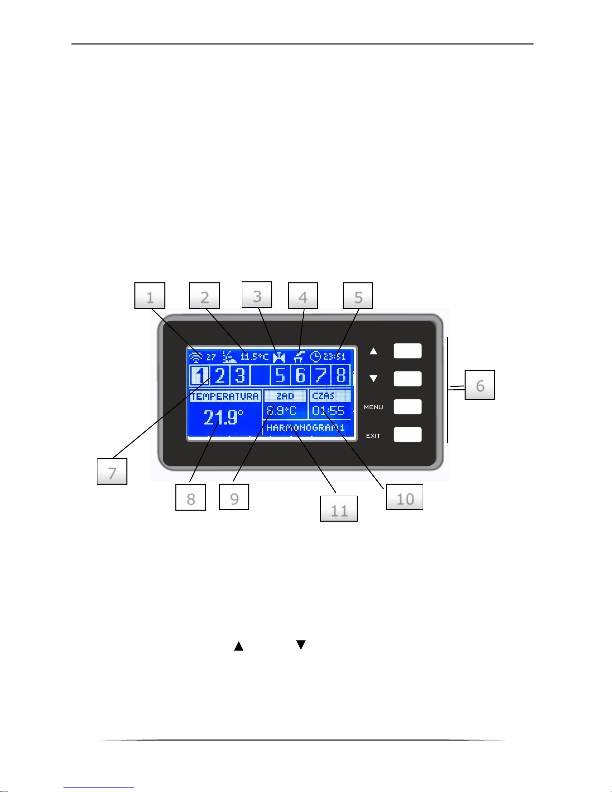
VI.b) View and description of the main screen
The device is controlled by means of buttons located next to the display
1. Information about the current channel of radio communication
2. External temperature
3. Icon signaling the pump's operation
4. Icon signaling the activated additional contact
5. Current time
6. Navigation buttons
7. Information on zones:
The visible digit means a connected room sensor transferring information on the current
temperature in a given zone. If the zone is insufficiently heated, the digit flashes. In the
case of an alarm in a given zone, an exclamation mark is displayed instead of the digit.
With the use of buttons as well as , the user may view the current settings of
subsequent zones.
8. Temperature of room sensor from a given zone
9. Set temperature in a given zone
10. Time until the end of manually adjusted set temperature
11. Information on the type of valid weekly schedule
3
1
6
7
8
10
2 3 4
5
9
11
Page 10

TECH
10
VII. Controller's functions – Main menu
Due to the numerous functions of the controller, the menu is divided into the Main Menu and the
Fitter's Menu.
VII.a) Chart of the controller's menu
Main menu
Manual operation
Pump
Dry contact
Valve 1...8
Channel
Czhannel 35;
Range: 0÷55
External sensor
Deactivated
Wireless
Sensors Zone 1...8
Deactivated
Activated
Set
Weekly control
Calibration
Hysteresis
Registration
Pump Delay
Language selection
Display contrast
Fitter's Menu
External sensor correction
Internet module
Deactivated
Activated
Registration
Information on software
DHCP
IP address
IP mask
Gateway address
DNS address
Module version
TimerInformation on software
Page 11

EU-2640 user’s manual
11
VII.b) Manual operation
This function allows the user to control the operation of particular devices. The user may manually
activate each device: the pump, the dry contact as well as particular valve actuators.
VII.c) Channel
This function is used to select the channel for radio communication with room sensors as
well as with the external sensor. The user should remember that this channel should be the same
as in all devices communicating with the EU-2640 controller. The user may select channels 0÷55.
The factory setting in devices cooperating with the EU-2640 controller is channel "35". The
channel needs to be changed only in the case of a conflict with other devices communicating with
one another with the use of a radio signal. In this situation, the user should remember to change
the channel in each device that is to communicate with the EU-2640 strip.
VII.d) External sensor
An external temperature sensor may be connected to the controller that allows the user to monitor
the current temperature on the main screen.
After the external sensor is mounted, the user should mark the option Wireless in the controller.
NOTE
The user should remember to adjust the same channel for radio communication as
in the EU-2640 controller. The factory setting in the external sensor is
channel "35".
Changing the communication channel in the external sensor:
In order to change the channel to a different one, the user should press and hold the channel
change button. When the LED on the sensor flashes two times, this means that the channel change
process has started. Holding the channel change button all the time, the user should wait until
the LED begins flashing again - the number of flashes corresponds to the number of the channel
(one flash - channel 1, 5 flashes - channel 5). When the requested channel number is adjusted,
the user should release the button. In order to adjust the channel back to 0, the user should
repeat the entire procedure and release the channel change button immediately after the first two
flashes of the LED.
LED
Channel change
button
Page 12

TECH
12
VII.e) Sensors
The submenu Sensors allows the user to adjust the operation parameters for particular zones.
When a given zone reaches the set value, the EU-2640 controller assigns a reheated status to this
zone until the temperature drops below the set value, reduced by hysteresis. When all zones are
reheated, the EU-2640 controller deactivates the pump as well as the dry contact at the same
time.
Submenu in each zone:
Deactivated / Activated
After the room sensor is activated and is assigned a given zone, it will be detected by the EU2640 strip. However, the operation of this sensor may be disabled by marking a suitable option.
Set value
The set temperature in a given zone depends on the settings of the selected weekly
schedule. However, the function Set Value allows the user to adjust a separate set value.
After it is determined, the display will show the screen with time settings for this
temperature. After this time expires, the set temperature in a given zone will again depend only
on the weekly schedule. When the duration of a given set temperature is adjusted as 00:00, this
temperature will be valid for an indefinite period of time.
The value of the set temperature along with the time until its end is displayed on the main
screen on a current basis (see Description of the main screen – screen number 8).
Weekly control
The EU-2640 controller has two types of weekly schedules:
1. Local schedule
This is a weekly schedule assigned only to a given zone. After the strip detects the room sensor,
it is automatically assigned as valid in a given zone. It may be edited freely.
2. Global schedule (Schedule 1..5)
These schedules have the same settings regardless of the zone and are non-editable from the
level of the strip (changes in global schedules are possible only via the Internet in cooperation
with an Internet module).
In order to assign the selected schedule to a given zone, the user only needs to mark the
option Select.
If the user wishes only to modify the global schedule as the current one in a given zone,
this is possible in the option Edit. After the user enters the desired modifications and saves them,
it is overwritten as a local schedule.
Zone 1..8
Deactivated
Activated
Set
Weekly control
Local
Select
Preview
Edit
Schedule 1..5
Select
Preview
Edit
Correction
Hysteresis
Registration
Register valce
Remove valve
Page 13

EU-2640 user’s manual
13
The type of weekly schedule assigned to the zone is visible on the main screen (see Description
of the main screen – screen number 9).
Edit
The schedule's editing commences after the user marks the option Edit.
The user may program no more than three time intervals with specific boundaries (with
accuracy to 15 minutes). A separate set temperature is assigned to each interval. The next step
is the adjustment of the set temperature valid beyond the time intervals.
The last step is selecting days of the week on which these settings are to be valid: by means of
the button , the user proceeds to edit the neighboring day of the week and it is marked /
unmarked with the use of the key .
Correction
The room sensor is calibrated during the installation or after a longer period of the regulator's
operation if the displayed external temperature differs from the actual temperature. Adjustment
range: -10 to +10⁰C with accuracy to 0.1⁰C.
Hysteresis
Hysteresis introduces the tolerance for the set temperature preventing unwanted oscillations at
minimum temperature deviations (ranging from 0 ÷ 10⁰C) with accuracy to 0.1°C.
Example: when the set temperature is 23⁰C and the hysteresis is adjusted to 2⁰C, the zone will
be assigned a status of insufficient heating after the temperature in the room drops to 21⁰C.
Registration
When wireless temperature regulator actuators are used, it is necessary to register a given
actuator in the zone. The user may select 8 zones (Valve 1…8), no more than 9 actuators may be
registered in each zone.
The registration process:
1. The temperature regulator actuator is mounted on the heater, the user waits until it is
calibrated (the calibration process ends with a short, double acoustic signal)
2. The user selects the number of the zone in which they wish to register a given actuator
and then the option Registration / Register Valve.
3. The user presses the registration button on the actuator. This needs to be done within
30 seconds from pressing the option Register Valve – after this time,
the EU-2640 controller considers the registration process
unsuccessful.
4. If the registration is conducted correctly, an appropriate message
will appear on the display informing about the successful
registration, as well as informing about the number of registered
valves. In the case of an error in the registration process, an
appropriate message will appear on the display. There are three
possible causes of errors:
a. Attempt to register more than nine actuators.
b. Attempt to register an already registered actuator.
c. No signal from the valve actuator within 30 seconds.
A digit informing about the number of registered valves is displayed apart from the icon Register
Valve.
Registration button on
wireless temperature
regulator actuator.
Page 14

TECH
14
VII.f) Pump
The EU-2640 regulator controls the operation of the pump – it activates the pump after the delay
time when any zone is insufficiently heated. When all zones are reheated (the set temperature is
reached), the controller deactivates the pump.
The function Delay allows the user to adjust the delay time for the pump's deactivation after the
temperature drops in any zone below the set value. The delay in pump activation is used for the
valve's actuator to open.
VII.g) Language selection
This function allows the user to change the controller's language version.
VII.h) Display contrast
This function allows the user to adjust the display's contrast to their individual needs.
VII.i) Fitter's menu
The Fitter's Menu is intended to be operated by people with appropriate qualifications and is used
primarily to adjust the controller's additional functions.
• External sensor correction
The external sensor is calibrated during the installation or after a longer period of the regulator's
operation if the displayed external temperature differs from the actual temperature. Adjustment
range: -10 to +10°C with accuracy to 0.1°C.
• Internet module
The EU-2640 regulator may operate with an Internet module which makes it possible to monitor
and change certain parameters via the Internet. Control of this type is possible only after
connecting an additional ST-5072 control module to the controller.
The Internet module may be connected with the EU-2640 controller via an RS cable. After the
module is connected, the user selects the option Registration. The code generated by the
controller is entered on the website – a detailed description may be found in the Internet module's
user's manual.
The Internet module is a device allowing the user to remotely control the regulator's operation
via the Internet. The user controls the condition of all valves on their personal computer at home.
After the user activates the Internet module and selects the DHCP option, the controller will
automatically download the following parameters from the local network: IP address, IP mask,
Gateway address and DNS address. In the case of any problems with downloading the network
parameters, it is possible to adjust these parameters manually. The method of obtaining the local
network parameters is described in the manual for the Internet module.
• Timer
This function allows the user to adjust the current time and day of the week.
VII.j) Information on software
After this option is activated, the display will show the boiler manufacturer's logo along with the
controller's software version.
Page 15

EU-2640 user’s manual
15
VIII. Protections and alarms
In order to ensure the maximum safe and trouble-free operation, the regulator is equipped with
a number of protections. An acoustic signal is activated in the case of an alarm and a relevant
message is shown on the display.
Automatic sensor control
If the temperature sensor or the external sensor are damaged, an alarm is activated, signaling
the relevant defect on the display, e.g. "Sensor damaged ".
The alarm will be active until the defect is removed (battery exchanged in the sensor or sensor
replaced with a new one) and until it is deleted from the strip level.
Deleting the zone alarm from the strip level:
The user marks the zone where the alarm is present (exclamation mark instead of the strip
number). The user presses the EXIT button – the screen will show two options to select from:
Reset
For a given period of time, the strip will try to communicate with the sensor again (this
may take several minutes). Until communicating with the sensor, the valve remains in
alarm position (closed – zone reheated). If the communication attempt with the zone is
not successful, the alarm occurs again.
Switch off
This function deactivates the zone from operation. Reactivation is possible via the option
of Activate – parameter: Main menu / Sensors / Zone 1..8.
Fuse
The regulator is equipped with tube fuse element WT 3.15A, dimensions 5x20mm, protecting the
network.
NOTE:
Higher amperage fuse should not be used as it may damage the controller.
Page 16
TECH
16
IX. Software update
NOTE
New software may be uploaded to the controller only by a qualified fitter. After the
software is changed, it is not possible to restore the previous settings.
To upload new software, the controller should be disconnected from the power supply. A flash
drive with the new software should be inserted to the USB port. Then, the user should connect
the controller to the power supply while holding the EXIT button. The user should hold the EXIT
button until a single acoustic signal is heard – this means that the new software is being uploaded.
After the task is completed, the controller will restart by itself.
CAUTION
Never switch the controller off when the software is being updated.
X. Technical data
Item
Specification
Unit
1
Power supply
V
230V/50Hz +/-10%
2
Maximum power consumption
W
7
3
Ambient temperature
O
C
5÷50
4
CH pump output load
A
0,5
5
CH temperature measurement range
O
C
0÷90
6
Measurement accuracy
O
C
1
7
Temperature strength of the sensor
O
C
-25÷90
8
Fuse element
A
3,15
Page 17
EU-2640 user’s manual
17
Declaration of conformity 185/2015
Hereby, we declare under our sole responsibility that EU-2640 230V,
50Hz thermoregulator manufactured by TECH, headquartered in
Wieprz (34-122), Biała Droga 31, is compliant with:
the regulation by the Ministry of Economy, Labour and Social
Policy (Journal of Laws No. 155, Item 1089) of August 21, 2007
implementing provisions of the Low Voltage Directive (LVD)
2006/95/EC,
an act of April 13, 2007 concerning Electromagnetic
Compatibility (Journal of Laws 07.82.556) implementing provisions of
EMC directive 2004/108/EC,
the regulation by the Ministry of Economy of May 8, 2013
concerning the essential requirements as regards the restriction of
the use of certain hazardous substances in electrical and electronic
equipment, implementing provisions of RoHS directive
2011/65/EU.
For compliance assessment, harmonized standards were used:
PN-EN 60730-2-9:2011, PN-EN 60730-1:2012
Date of CE marking: 10-2015
Page 18

TECH
18
Page 19

EU-2640 user’s manual
19
Page 20

TECH
20
 Loading...