

Page 1
ST – 26
Manual Guide
Page 2

ST-26 – Manual Guide
TECH
Declaration of compatibility number 7/2006
We, the TECH Company, 14, St. Batorego Street, 34-120
Andrychów, declare with absolute liability that this
thermoregulator ST – 26 230V, 50 HZ, produced by our
company, fulfils the requirements of Ordinance of the
Minister of Economy, Labour and Social Policy (Dz.U.
03.49.414) from 12th March 2003, implementing the
provisions of Low Voltage Directive 73/23/EEC and
Ordinance of the Minister of Infrastructure (Dz.U.
03.90.848) from 2nd April 2004 implementing the
provisions of Directive EMC 89/336/EEC.
To conformity assessment there were used harmonized
standards
PN-EN 60730-2-1:2002.
The product was marked with CE for the first time on 3
rd
January 2006
Andrychów, 03.01.2006r
- 2 -
Proprietors:
Paweł Jura, Janusz Master
Page 3

Attention!
TECH
THE LIVE ELECTRIC DEVICE!
Before doing any activities connected with
power supply (connecting wires,
installation of the device, etc) it is
necessary to make sure that the regulator
is not connected to the grid!
Assembly and installation should only be
carried out by qualified electrician.
Before activating the controller it is
necessary to do the measurement of
effectiveness of resetting electric motors,
the boiler and the measurement of
insulation of electric wires.
- 3 -
Page 4

ST-26 – Manual Guide
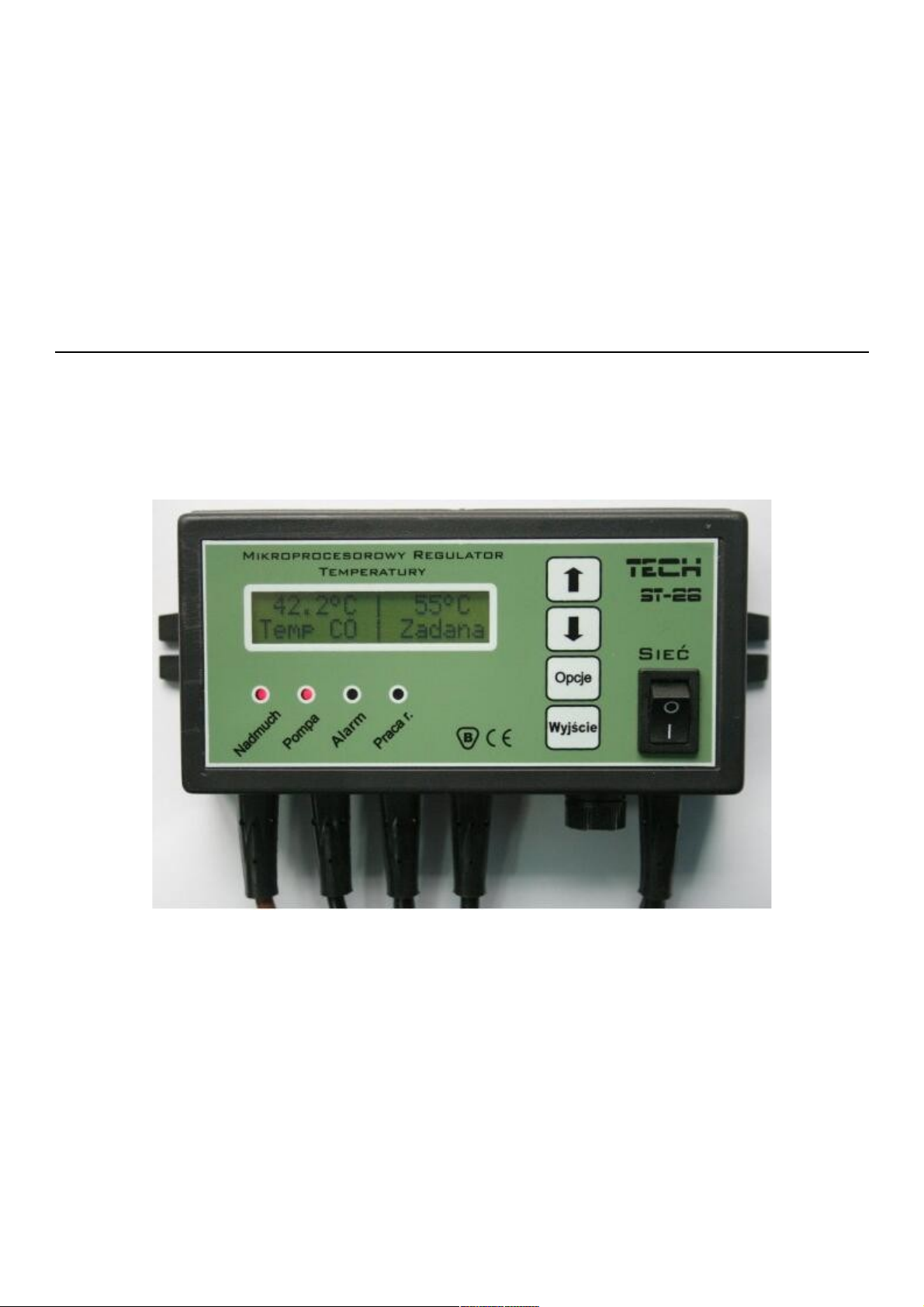
Entrance to
submenu and
confirmation of
settings button
PLUS button
MINUS button
Return from the
menu and cancel
the settings button
I. Description
The temperature regulator ST-26 is designed for the central heating
boiler. It controls the circulation of water pump and air-blow (fan).
● If the temperature of the stove is lower than Set temperature, the
regulator is in operating mode in which the air blow is working all the
time.
● If the temperature of the stove is equal or higher than Set
temperature, the regulator is in back-up mode.
- 4 -
Page 5

TECH
II. Functions of the regulator.
This section describes functions of the regulator, the way of
changing settings, and moving the menu.
II.a) Main page
62oc 72oc
CH temp req temp
During normal working of the regulator in the LCD display you can
see the main page on which there are displayed following informations:
● Temperature of the stove
● Set temperature
This screen makes possible quick change of set temperature by the
PLUS and MINUS buttons. Pressing the options button will move the
user to first level menu. On the display there are displayed the two first
lines of the menu. On the menu you can move by using PLUS and
MINUS buttons. Pressing the Options button will move you to the next
submenu or it will start the option. EXIT moves you back to main menu.
II.b) Lighting
The lighting function is designed for turning the fan on and off
during continuous controller’s work. If the boiler reaches the
temperature over 30°C and the boiler does not reach set temperature,
then the button fulfils START-STOP function. By using this function you
can turn the fan on and off while his working. It is signalized by pulsar
shining Manual Work diode. This function is designed for enabling the
user safe service of the boiler. When the fan is on, you mustn’t open the
hearth’s door.
II.c) Manual Work
62oc 72oc
CH temp req temp
In order to user’s comfort, the regulator has Manual Work. In this
function, every element of the system is turned on and off irrespective of
the rest.
- 5 -
Page 6

ST-26 – Manual Guide
Air blow
pump
Pressing OPTIONS buttons activates the air-blow. The air-blow
remains activated till pressing again OPTIONS.
Air blow
Pump
Pressing MENU turns on / off the water’s pump.
pump
ALARM
Pressing MENU turns on / off the alarm
II.d) Air-blow’s speed
62oc 72oc
CH temp req temp
Air-blow's speed
air-blow's break
03 gear
air-blow's speed
This function controls the fan’s working speed. Range of adjustment
is from 1 to 6 (it can be said that these are fan’s gears). The biggest the
gear is, the faster the fan is working. The first gear – it is a minimum
speed of the fan and 6
To change the range of fan’s gears, press the button PLUS and
th
gear is a maximum speed of the fan.
MINUS. The fan always turns on in the beginning with full speed – it
makes possible turning the fan on when the motor is a little dusty.
- 6 -
Page 7

TECH
II.e) Burning
62oc 72oc
CH temp req temp
Air-blow's break
Air-blow's work
This function is used to regulate working the boiler during its
working in back-up mode. It prevents from extinguishing the boiler when
the temperature of the boiler remains over set temperature.
In this function you can set time of air-blow’s break. After set time, on
the time set by the boiler’s producer, the air-blow turns on. The time of
air-blow working you can change in the service functions. Time of
burning’s break you should set dependence on the fuel and a type of the
boiler.
ATTENTION: Wrong setting the options included above can cause
continuous rising the temperature! Time of burning’s break shouldn’t be
too short.
II.f) Minimal revolutions
62oc 72oc
CH temp req temp
1 gear
minimal rev.
On this gear the fan reaches set temperature – for instance you set
the second gear, and the fan will be gradually slowing down by every
single degree Celsius from the 6th gear to the minimal value (that is 2).
The fan will be working on the 2nd gear till reaching set temperature.
- 7 -
Page 8

ST-26 – Manual Guide
II.g) Factory settings
The fan is tentatively preset to work. However, you should adjust it
to your own needs. In every moment it is possible to return to factory
settings.
62oc 72oc
CH temp req temp
f
factory settings
no
yes
III. Protection
In order to ensure maximum safe and failure-free working, the
regulator has a number of protections. In the case of an alarm, the sound
signal encloses and there appears adequate message on the display.
When you press MENU the controller returns to working.
III.a) Thermal protection
It is additional mini bimetallic sensor (it is placed near the stove
sensor) which cuts off the output of the fan in the case of exceeded
90°C. It prevents from boiling the water in the case of damage of
thermoregulator.
III.b) Automatic controlling the sensor
In the case of damage of central heating temperature’s sensor, the
alarm becomes active and it signals additionally the fault on the display.:
A L A R M
sensor damaged
The air-blow is turned off. The pump is turned on irrespective from
current temperature. The regulator is waiting for pressing MENU button
and then the alarm is turned off and the controller returns to normal
working.
- 8 -
Page 9

TECH
III.c) Temperature protection
In the case of damage of bimetallic sensor the regulator has
additional protection: after exceeding the 95°C temperature, the alarm is
turned on and it is signaled on the display:
A L A R M
temp too high
III.d) The fuse
The regulator has cartridge fuse WT 1,6A which protects the grid.
IV. Maintenance of the controller.
Before heating season and in the time of his duration there should
be checked the technical status of the wires in the controller ST 26. The
fastening of the controller, cleaning up and dusting must be checked, too.
It must be done the measurement of effectiveness of motors’ earthing
(pump and blow)
L.p. Specification Unit
1 Power supply V 230V/50Hz +/-10%
2 Power consumption W 2
3 Surroundings temperature
4 Output load of circulating pump A 1
5 Temperature measuring range
O
C 00
O
C 0
6 Measuring accuracy
7 Temperature setting range
8 Temperature strength of sensor
O
C 1
O
C
O
C -
- 9 -
Page 10
ST-26 – Manual Guide
V. Service
In the case of appearing faults you should contact with:
TECH Civil Partnership
14, St. Batorego Street, 34-120 Andrychów, Poland
Phone: +48 33 8705105, +48 33 8759380
VI. Assembly
Attention: The assembly should be done only by the person with
proper qualifications! The device in this time mustn’t be live (you should
ensure that plug is disconnected from the grid)!
ATTENTION: wrong connection of wires can cause the
damage of the regulator!
The regulator cannot work in closed circuit of central heating. The
balance tank, safety valves and pressure valves that protect by boiling
the water in the central heating circuit must be mounted.
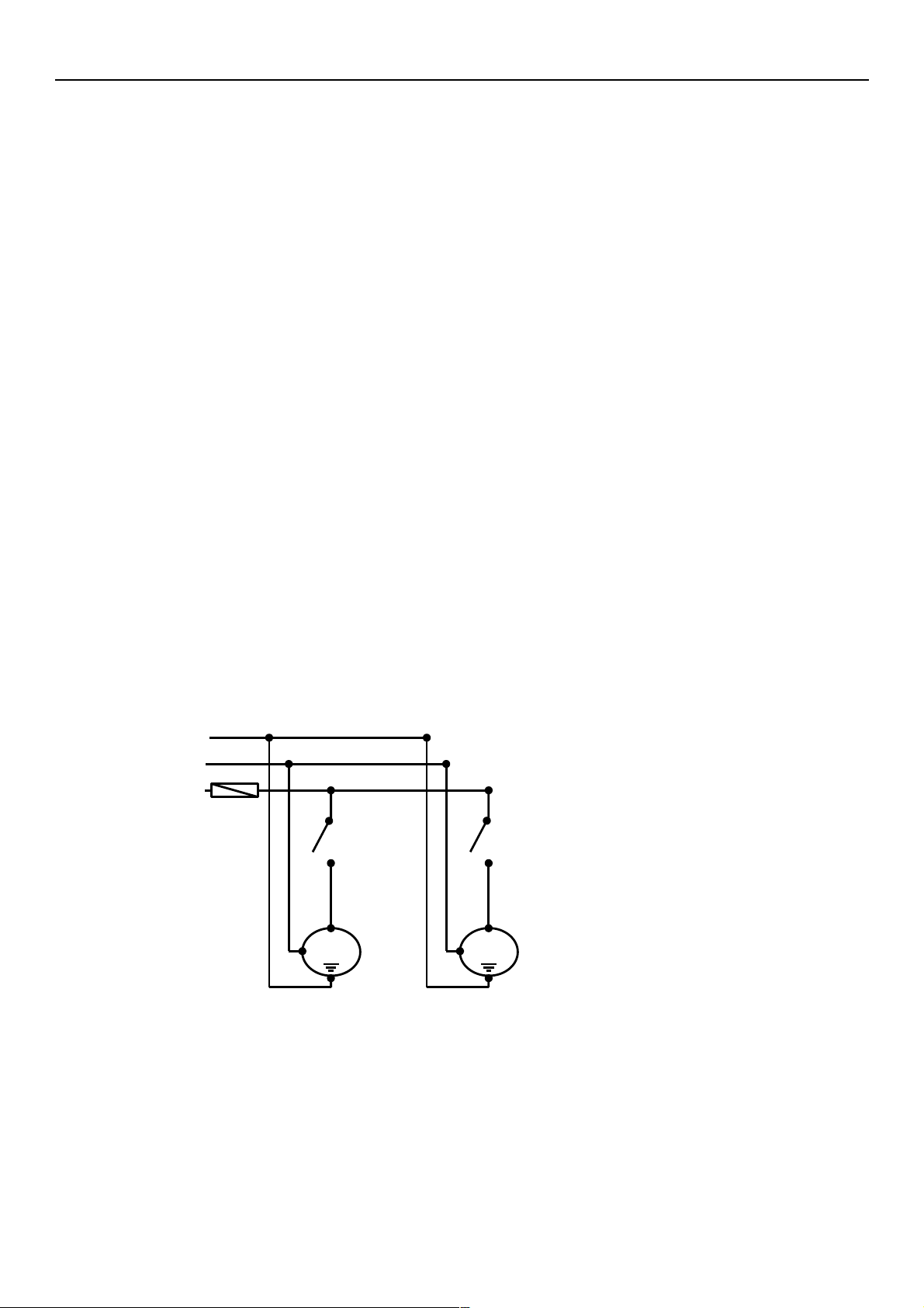
VI.a) The diagram of cables connection to the
controller.
While assembly of wiring of the controller you should pay special
attention to correct connecting ground wires.
PE
N
L
FUSE 6.3A
relay
~
230V AC
air-blow
~
230V AC
central heating pump
relay
PE – earthing (yellow and green)
N – neutral (blue)
L – phase (brown)
- 10 -
Page 11

Spis treści
II. Functions of the regulator.....................................................5
II.a) Main page....................................................................5
II.b) Lighting.......................................................................5
II.c) Manual Work.................................................................5
II.d) Air-blow’s speed............................................................6
II.e) Burning .......................................................................7
II.f) Minimal revolutions.......................................................7
II.g) Factory settings............................................................8
III. Protection.........................................................................8
III.a) Thermal protection.......................................................8
III.b) Automatic controlling the sensor....................................8
III.c) Temperature protection.................................................9
III.d) The fuse.....................................................................9
IV. Maintenance of the controller...............................................9
V. Service.............................................................................10
VI. Assembly........................................................................10
VI.a) The diagram of cables connection to the controller..........10
Page 12

WARRANTY
The TECH Company guarantees the buyer correct functioning
of the device for 30 months from the date of purchasing. Guarantor
obliges to repair without charge of the device if the fault appears
from the guilt of the producer. The device should be delivered to
the place where the product was purchased. All connected with
these costs incur the user.
ATTENTION!! The temperature sensor mustn’t be
immersed in any liquid (oil etc.). It menaces damage of the
controller and the loss of the warranty!
You mustn’t remove insulation that is put on the
bimetallic minisensor. Its removal can cause that the
controller will wrong work.
The warranty does not include damages arising out of misuse,
or due to user; the mechanical damages and appeared due to
atmospheric discharge, over voltage, and short-circuit.
The warranty without attached receipt, date of sale, date of
delivery and signatures is invalid.
The warranty card is the only base of free repair.
In the case of loosing or destroying the warranty card the producer
does not give the duplicate
................... ................... ................
Date of delivery Salesman’s stamp Date of sale
 Loading...