

Page 1
L-6 User’s manual
1
User’s manual
L-6
Page 2
TECH
2
I. Safety
Before using the device for the first time the user should read the following regulations
carefully. Not obeying the rules included in this manual may lead to personal injuries or
controller damage. The user’s manual should be stored in a safe place for further
reference. In order to avoid accidents and errors it should be ensured that every person
using the device has familiarized themselves with the principle of operation as well as
security functions of the controller. If the device is to be sold or put in a different place,
make sure that the user’s manual is there with the device so that any potential user has
access to essential information about the device.
The manufacturer does not accept responsibility for any injuries or damage resulting
from negligence; therefore, users are obliged to take the necessary safety measures
listed in this manual to protect their lives and property.
WARNING
High voltage! Make sure the regulator is disconnected from the mains before
performing any activities involving the power supply (plugging cables, installing
the device etc.)
The device should be installed by a qualified electrician.
Before starting the controller, the user shoud measure earthing resistance of the
electric motors as well as the insulation resistance of the cables.
The regulator should not be operated by children.
WARNING
The device may be damaged if struck by a lightning. Make sure the plug is
disconnected from the power supply during storm.
Any use other than specified by the manufacturer is forbidden.
Before and during the heating season, the controller should be checked for
condition of its cables. The user should also check if the controller is properly
mounted and clean it if dusty or dirty.
!
!
Page 3
L-6 User’s manual
3
II. Description of the device
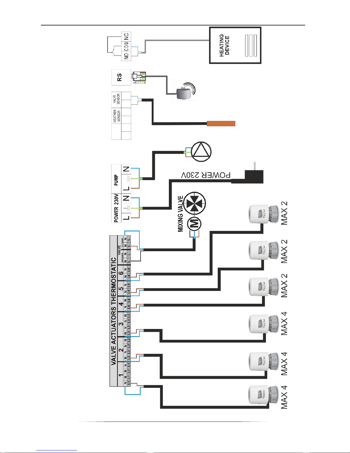
L-6 external controller is intended for both wired and wireless control of the valves. It
allows the user to limit considerably the power consumption due to precise control of the
room temperature. Thanks to advanced software, the device offers a wide range of
functions:
control of the mixing valve
control of up to 18 thermostatic valves via 6 room regulators (wired connection)
o 3 room regulators may support 12 actuators (the maximum of 4 actuators per one
regulator)
o 3 room regulators may support up to 6 actuators (the maximum of 2 actuators per
one regulator)
possibility of controlling thermostatic valves via radio signal
one 230V pump output
supporting pump with speed control (via PWM signal)
voltage-free contact
possibility of connecting ST-65 GSM module allowing the user to control some of
the functions via a mobile phone.
possibility of connecting ST-500 Ethernet module allowing the user to control some
of the functions and view certain parameters via the Internet
possibility of connecting an external control panel with RS communication
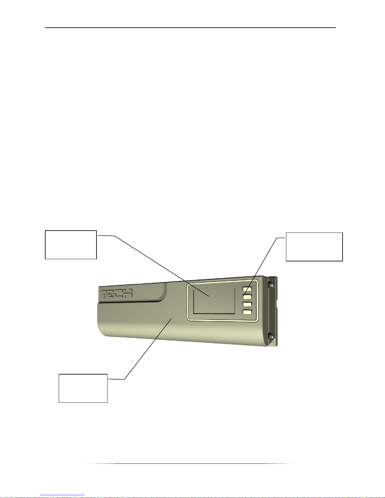
Buttons used
to navigate
the menu
Display
Controller
cover
Page 4
TECH
4
III. Controller installation
The controller should be installed by a qualified person.
WARNING
Risk of fatal electric shock from touching live connections. Before working on the
controller switch off the power supply and prevent it from being switched on again.
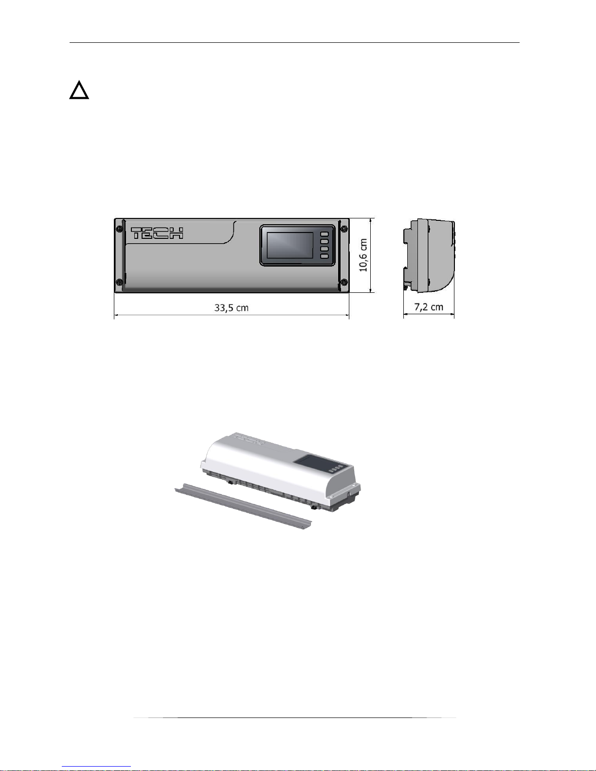
L-6 regulator may be installed as a free-standing device or as a panel mountable on a
wall.
The controller may be installed on a DIN strip.
In order to wire up the controller, the cover should be removed.
!
Page 5
L-6 User’s manual
5
Page 6
TECH
6
IV. Wireless communication
L-6 controller enables wireless communication with the following devices:
Function
Configuration
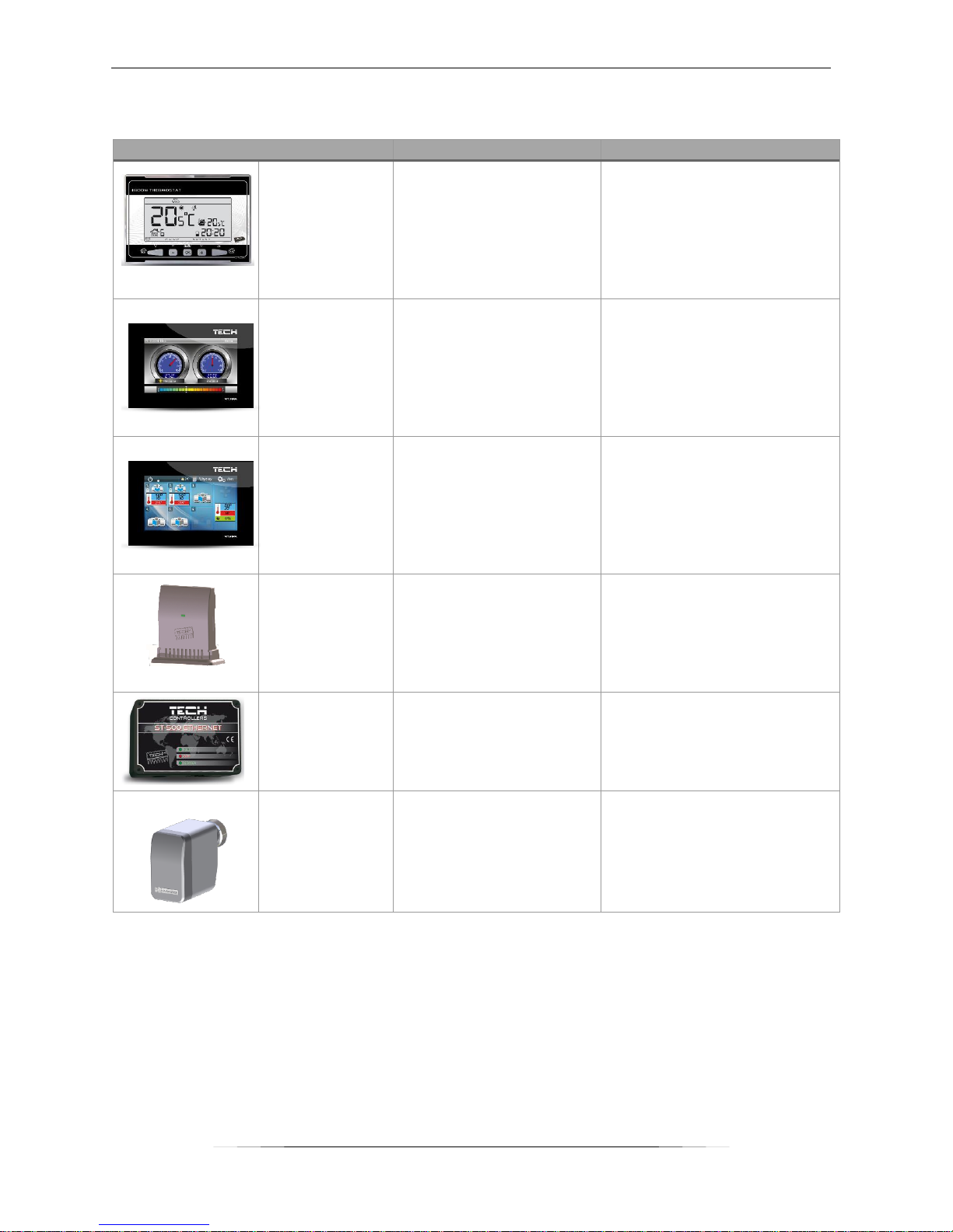
ST-290v4
ST-292v4
two-state
room
regulators
Sending information
about
sufficient/insufficient
temperature in a given
zone
- the room regulator needs
to be assigned to a
selected area in the room
regulator menu
- the current
communication channel
must be the same as in L-6
ST-286
two-state
room
regulators
(colour)
Sending information
about
sufficient/insufficient
temperature in a given
zone.
- the room regulator needs
to be assigned to a
selected area in the room
regulator menu
- the current
communication channel
must be the same as in L-6
ST-285
master room
regulator
Enabling the user to
view and change
certain parameters of
the room regulators
assigned to the zones
- an appropriate option
should be selected in ST-L6 menu (Main menu/
Fitter’s menu/ Room
regulator/ TECH regulator)
- ST-260 module is
necessary
ST-291
external
temperature
sensor
Enabling the user to
view the external
temperature and use
weather-based control
of the built-in valve
module
- the current
communication channel
must be the same as in L-6
ST-500
Internet
module
Enabling the user to
view and change
certain operation
parameters of L-6 via
the Internet
- additional ST-260 module
is necessary
STT-868
wireless
thermostatic
actuator
Helping to maintain the
pre-set temperature
- it needs to be registered
in L-6 controller.
Page 7

L-6 User’s manual
7
V. First start-up
In order for the controller to operate correctly, the following steps must be followed when
starting the device for the first time:
1. Wire up the controller
2. Switch on the controller.
3. If the set includes the master room regulator (ST-285), it needs to be activated
in the controller menu: Main Menu/ Fitter’s menu/ Room regulator/ TECH
regulator.
4. If the set includes ST-500 Internet module, it needs to be activated in the
controller menu: Main menu/ Fitter’s menu/ Internet module/ ON.
5. Define the type of external sensor by selecting one of the options in the controller
menu: OFF, Standard or Wireless (ST-291) in the controller menu: Main Menu /
External sensor.
6. Configuration of room regulators sending information about sufficient/insufficient
temperature in a given zone.
a. The user should check if the selected communication channel in the room
regulators is the same as in L-6. ‘0’ is the default channel in all devices. If
there is a conflict with other devices using radio communication, the user
needs to select a different channel.
Channel change in ST-286 controller:
In order to change the channel, press Controller settings in
the main menu and go to Channel selection. After a channel
is selected, confirm the change by pressing OK.
Channel change in ST-290v4 or ST-292v4:
ST-290v4
Screenshot
ST-292v4
- Press and hold MENU
button to view the controller
functions.
- Using arrows and
go to channel change
(see: screenshot)
- Select a desired channel by
using PLUS and MINUS
buttons.
- Confirm the change by
pressing MENU and holding it
for a few seconds.
- Press MENU to view the
controller functions
- Press MENU button until the
channel change panel appears
on the screen. (see:
screenshot)
- Using and
buttons select a desired
channel.
- Confirm the change by
pressing MENU and holding it
for a few seconds or by
pressing EXIT.
b. Each room regulator should be assigned to a zone.
NOTE
Each room regulator should be assigned to only one zone. If there are more room
regulators assigned to the same zone, L-6 controller will not work properly.
!
Page 8

TECH
8
How to assign ST-286room regulator to a selected zone:
Press Controller settings in the main menu and go to
Regulator number (zone number). Select a zone number and
confirm by pressing OK icon.
How to assign ST-290v4 or ST-292v4 to a selected zone:
ST-290v4
Screenshot
ST-292v4
- Press and hold MENU
button to view the controller
functions
- Using and
go to zone selection (see:
screenshot)
- Zone change function is
secured with 215 code – use
PLUS and MINUS buttons to
enter the first digit of the
code (‘2’). Press MENU to
confirm. Follow the same
procedure with ‘1’ and ‘5’.
- Press MENU to view the
controller functions
- Press MENU button until the
zone selection panel appears
on the screen. (see:
screenshot)
- Zone change function is
secured with 215 code - use
and buttons to
enter the first digit of the
code (‘2’). Confirm by
pressing and holding MENU
button. Follow the same
procedure with ‘1’ and ‘5’.
- Choose a desired zone
number using PLUS and
MINUS buttons.
- Press and hold MENU to
confirm the change.
- Choose a desired zone
number using
buttons.
- Confirm the change by
pressing MENU and holding it
for a few seconds or by
pressing EXIT.
7. If wireless thermostatic actuators are used, they need to be registered in the
zones.
VI. How to use the controller
V.a) Principle of operation
L-6 controls the CH pump switching it on when the temperature in any of the six zones
or the built-in valve is too low. The controller receives temperature information from the
subordinate room regulators assigned to particular zones. If the temperature in any of
the zones is too low, the controller opens the valves in this particular zone.
L-6 receives temperature information from different zones via room regulators e.g. ST292v4, ST-290v4 or ST-286. Room regulators use wireless communication to send
information to the L-6 controller.
It is possible to connect a master room regulator (ST-285) which controls the operation
of the room regulators in all zones via wireless communication.
To each zone the user may assign wired valve actuators and the maximum of 9 wireless
actuators communicating with L-6 via radio signal (registration is required).
Page 9

L-6 User’s manual
9
V.b) Main screen view and description
The user operates the controller using buttons located next to the display.
1. Information about active master room regulator (ST-285)
2. Current time
3. Buttons used to navigate
4. Current communication channel
5. Information about the zones:
A digit displayed on the screen refers to the room regulator which reports
insufficient/sufficient room temperature. If the digit is flashing, the room temperature is
too low – the valves are open. If a digit is not displayed, there is no signal from the room
regulator assigned to this number.
6. Information about active built-in valve
V.c) Controller functions – main menu.
Due to a great number of functions offered by the controller, the menu is divided into
Main menu and Fitter’s menu.
3
1
2
3
4 5 6
7
Page 10

TECH
10
V.c.1) Block diagram – Main menu
V.c.2) Manual operation
This function enables the user to control operation of
particular devices. Each of the following devices may be
switched on manually: main valve, pump, voltage-free
contact and particular valve actuators.
Main menu
Manual mode
Main valve
Pump
Voltage-free contact
Valve 1-6
Channel 0 Channel; range: 0÷20
Main valve
Valve status
Pre-set valve temperature
Opening time
Valve type
Weather-based control
Factory settings
External sensor
OFF
Standard
Wireless
Pump Delay
Language selection
Display contrast
Fitter's menu
Registration
Room regulator
Internet module
Clock
Page 11

L-6 User’s manual
11
V.c.3) Channel
This function is used to select the channel for wireless
communication with the room regulators and the external
sensor. The user needs to select the same channel in all
devices communicating with the L-6 controller. The range
of channels is 0-20.
‘0’ is the default channel in the devices cooperating
with L-6. The channel must be changed only if there
is a conflict with other devices using radio
communication. In such a case the user must
remember to change the channel in all the devices
communicating with L-6.
V.c.4) Main valve
L-6 controller is equipped with a built-in module
controlling the mixing valve. There is a range of
parameters regulating the valve operation and allowing
the user to customize it to individual needs.
Valve status
In order to activate the valve select ON.
Pre-set valve temperature
This function is used to define the pre-set temperature of
the valve. It is measured by the valve sensor.
Opening time
This parameter defines the time needed for the valve to
open from 0% to 100%. The value should be adjusted to
the valve actuator used (information on the rating plate).
Valve type
This function is used to select the type of valve to be
controlled:
CH VALVE – this option is selected when the user
wants to control the CH circuit temperature
FLOOR VALVE - this option is selected when the
user wants to control the temperature in the
underfloor heating circuit. This function protects
the underfloor heating system against hazardous temperature. If CH valve type is
Page 12

TECH
12
selected when the valve is connected to the underfloor heating system, the fragile
installation may be damaged.
Weather-based control
For the function of weather control to be active, the
external sensor mustn't be exposed to sunlight or
influenced by the weather conditions. After it is installed
in an appropriate place and wired up, weather control
function needs to be activated in the controller menu.
For the valve to operate correctly, the user defines the
pre-set temperature (behind the valve) for 4 intermediate
external temperatures:
-20ºC, -10ºC, 0ºC and 10ºC.
The user selects external temperature value using LEFT
and RIGHT arrows and defines a corresponding pre-set
temperature value using DOWN and UP arrows.
Subsequently, the display shows the heating curve.
Heating curve – it is a curve according to which the pre-
set controller temperature is determined, on the basis of
external temperature. In our controller, this curve is
constructed on the basis of four pre-set temperatures for
respective values of external temperatures.
The more points constructing the curve, the greater its
accuracy, which allows its flexible shaping. In our opinion,
four points seem a very good compromise ensuring decent
accuracy and easiness of setting the course of this curve.
NOTE
After weather-based control is switched on, pre-set valve temperature parameter is
not available. (Main menu-valve settings)
Factory settings
This function enables the user to restore the factory
settings for a particular valve. Restoring factory settings
does not change the selected valve type (CH or floor).
V.c.5) External sensor
The controller may be connected to a standard or wireless
external temperature sensor which enables weatherbased control of the built-in valve. Current external
temperature is displayed on the main screen. After the
external sensor is installed, the user needs to
define its type: standard or wireless.
!
Page 13

L-6 User’s manual
13
WARNING
If a wireless external sensor is used, the user needs to check if the same communication
channel is selected in L-6 controller. ‘0’ is the default channel in the external sensor.
Channel change in the external sensor:
Press and hold the channel change button in order to change the communication channel.
When the control light flashes twice, the process of channel change has been initiated.
Hold the button and wait until the light starts flashing again. The number of flashes
corresponds to the channel number (1 flash – channel 1; 5 flashes – channel 5). After
the desired channel has been selected, release the button. In order to return to channel
0, repeat the procedure releasing the button after the first two flashes.
V.c.6) Pump
L-6 controls the pump operation switching it on when
necessary.
The pump is activated when the temperature in any of the
zones is too low or if the pre-set temperature of the builtin valve has not been reached (the built-in valve needs to
be active). If all room regulators report sufficient
temperature and the pre-set temperature of the built-in
valve has been reached (if the valve is active), the
controller switches off the pump.
Delay function allows the user to define the
time of pump activation delay after the
temperature in any of the zones is too low or
after the valve temperature drops below the
pre-set value.
V.c.9) Language selection
This function is used to choose the language version.
!
Control light
Channel
change button
Page 14

TECH
14
V.c.10) Display contrast
This function enables adjustment of display contrast.
V.c.11) Fitter’s menu
Fitter’s menu should be accessed by a qualified person.
It is intended mostly for adjusting additional functions of
the controller.
1) Registration
Wireless thermostatic actuators must be registered in
particular zones. The user may choose from 6 zones
(Valve 1-6). The maximum of 9 actuators may be
registered in one zone.
Registration procedure:
1. Install the thermostatic actuator on the radiator.
2. Go to Registration in the Fitter’s menu of L-6
controller.
3. Choose the zone number in which the actuator
will be registered and select Registration.
4. Press registration button on the controller. It
must be done within 30 seconds from selecting
Registration option in the menu – after this time
the registration process is considered unsuccessful.
5. If the registration process has been successfully completed,
the display shows the message confirming the registration
as well as the number of registered valves. If an error
occurs during the registration process, the display shows an
appropriate message. There are three possible causes of
errors:
o an attempt to register more than 9 actuators
o an attempt to register an actuator which has
already been registered
o no signal from the valve actuator within 30
seconds
2) Room regulator
L-6 controller may cooperate with a master room regulator
(ST-285) which enables the user to:
view the status of particular valves
change the pre-set temperature of a given zone – in
the case of using subordinate room regulators with
RS communication (ST-286)
view the external temperature
Registration button on
the wireless
thermostatic actuator
Page 15

L-6 User’s manual
15
view the status of an additional contact (ON/OFF)
Regulator TECH option needs to be selected in order for
the communication between L-6 and the room regulator
to be active.
3) Internet module
L-6 controller may cooperate with the Internet module
allowing the user to view and change some of the
parameters via the Internet. This type of control is
available only after purchasing and connecting an
additional controlling module ST-500 which is not included
in the standard controller set.
The Internet module may be connected to L-6 controller
with RS cable. Wireless communication is possible if an
additional module - ST-260 is used.
Internet module is a device enabling the user remote
control of the CH boiler via the Internet or local network.
The user controls the status of all valves on the home
computer screen.
If two-state room regulators are used, the user may check
if the temperature is sufficient/insufficient. Room
regulators with RS communication enable the user to view
the current room temperature as well as change its preset value.
After switching the module on and selecting DHCP option,
the controller automatically downloads such parameters
as IP address, IP mask, gateway address and DNS
address from the local network. If any problems arise
when downloading the network parameters, they may be
set manually. The procedure of obtaining these parameters is described in detail in the
instruction manual of the Internet module.
Module password reset function may be used when the user has changed the default
password on the login page. If the user's new password is lost, the default password may
be restored by resetting the module password.
4) Clock
This function is used to set current time and day of the
week.
Page 16

TECH
16
VII. Protections and alarms
In order to ensure safe and failure-free operation, the regulator has been equipped with
a range of safeguards. In case of alarm, a sound signal is activated and the display shows
an appropriate message.
Automatic sensor control
If the valve temperature sensor or the external sensor is damaged, an alarm sound is
activated and the display message informs about the failure
e.g. 'Sensor damaged'. The pump is active regardless of the current
temperature.
The alarm is active until a new sensor is installed.
Fuse
The regulator has a WT 6,3A tube fuse-link (5x20mm) protecting the network.
CAUTION: Higher amperage fuse should not be used as it may damage the controller.
VIII. Technical data
No.
Specification
Unit
1
Supply voltage
V
230V/50Hz +/-10%
2
Maximum power consumption
W
7
3
Ambient temperature
O
C
5÷50
4
CH pump output load
A
0,5
5
Range of CH temperature measurement
O
C
0÷90
6
Accuracy of measurement
O
C
1
7
Thermal resistance of the sensor
O
C
-25÷90
8
Fuse link
A
6,3
Page 17

L-6 User’s manual
17
Table of contents
I. Safety .......................................................................................................... 2
II. Description of the device .............................................................................. 3
III. Controller installation ................................................................................... 4
IV. Wireless communication ............................................................................... 6
V. First start-up .............................................................................................. 7
VI. How to use the controller ............................................................................. 8
V.a) Principle of operation .................................................................................. 8
V.b) Main screen view and description ................................................................. 9
V.c) Controller functions – main menu. ................................................................ 9
V.c.1) Block diagram – Main menu ................................................................. 10
V.c.2) Manual operation ................................................................................ 10
V.c.3) Channel ............................................................................................. 11
V.c.4) Main valve ......................................................................................... 11
V.c.5) External sensor .................................................................................. 12
V.c.6) Pump ................................................................................................ 13
V.c.9) Language selection ............................................................................. 13
V.c.10) Display contrast ................................................................................ 14
V.c.11) Fitter’s menu .................................................................................... 14
1) Registration .......................................................................................... 14
2) Room regulator ..................................................................................... 14
3) Internet module .................................................................................... 15
4) Clock .................................................................................................... 15
VII. Protections and alarms ............................................................................... 16
Fuse .............................................................................................................. 16
VIII. Technical data ........................................................................................ 16
Page 18

TECH
18
We are committed to protecting the environment. Manufacturing
electronic devices imposes an obligation of providing for
environmentally safe disposal of used electronic components and
devices. Hence, we have been entered into a register kept by the
Inspection For Environmental Protection. The crossed-out bin
symbol on a product means that the product may not be disposed
of to household waste containers. Recycling of wastes helps to
protect the environment. The user is obliged to transfer their
used equipment to a collection point where all electric and
electronic components will be recycled.
Page 19

L-6 User’s manual
19
EU Declaration of conformity
Hereby, we declare under our sole responsibility that L-6 manufactured by TECH,
headquartered in Wieprz Biała Droga 31, 34-122 Wieprz, is compliant with:
Directive 1999/5/EC of the European Parliament and of the Council of 9 March 1999 on radio
equipment and telecommunications terminal equipment and the mutual recognition of their
conformity,
Directive 2014/35/EU of the European Parliament and of the Council of February 26, 2014 on
the harmonisation of the laws of Member States relating to the making available on the market
of electrical equipment designed for use within certain voltage limits (EU Journal of Laws L 96,
of 29.03.2014, p. 357),
Directive 2014/30/EU of the European Parliament and of the Council of February 26, 2014 on
the harmonisation of the laws of Member States relating to electromagnetic compatibility (EU
Journal of Laws L 96 of 29.03.2014, p.79),
Directive 2009/125/EC establishing a framework for the setting of ecodesign requirements for
energy-related products, the regulation by the Ministry of Economy of May 8, 2013 concerning
the essential requirements as regards the restriction of the use of certain hazard-ous
substances in electrical and electronic equip-ment, implementing provisions of RoHS directive
2011/65/EU.
For compliance assessment, harmonized standards were used:
PN-ETSI EN 301 489-1 V1.9.2:2012
PN-ETSI EN 301 489-3 V1.6.1:2014-03
PN-ETSI EN 300 220-1 V2.4.1:2013-02
PN-ETSI EN 300 220-2 V2.4.1:2013-02
PN-EN 60730-2-9:2011, PN-EN 60730-1:2012
Wieprz, 12. 10. 2015
Page 20

TECH
20
 Loading...