

Page 1
3001 Red Hill Ave, Suite 1-204
Costa Mesa, CA 92626
Phone +1-714-641-1709
Fax +1-714-641-1569
Triton+ User’s Manual
Page 2

T able of Contents
Before You Begin.....................................................................................................3
1.1 Introduction................................................................................................3
1.2 Package Contents.....................................................................................3
1.4 Computer Requirements..........................................................................3
1.5 Installation Overview.................................................................................3
Installation................................................................................................................4
2.1 Select the Driver Setup File for Your OS.................................................4
2.2 Install Driver File Onto Your Computer....................................................5
2.3 Connect the Power Supply To the Amplifier............................................7
2.4 Plug In the Power Supply Into an AC Outlet ...........................................8
2.5 Connect the USB Cable To the Amplifier and the Computer.................9
2.6 Turn On the Amplifier................................................................................9
2.7 Associating the Driver and the Amplifier (Windows XP).......................10
Getting Started With TecellaLab...........................................................................13
3.1 Install TecellaLab....................................................................................13
3.2 Launch TecellaLab..................................................................................15
3.3 Start Acquisition ......................................................................................16
3.4 Changing Gain (Rf setting).....................................................................17
3.5 Changing Source....................................................................................18
3.8 Save Data To a File................................................................................19
3.9 Convert Data to Tab Delimited or ATF Format.....................................22
3.10 Using TecellaLab..................................................................................22
Getting Started With WinWCP..............................................................................24
4.1 Download WinWCP Setup File..............................................................24
4.2 Download WinWCP User Guide............................................................24
4.3 Install WinWCP.......................................................................................24
4.4 Start WinWCP.........................................................................................24
4.5 Set Laboratory Interface Card to “Tecella Triton”..................................25
4.3 Using WinWCP.......................................................................................26
Connecting To Your Setup....................................................................................27
Page 3

2
Using TecellaLab...................................................................................................28
Hardware Calibration.............................................................................................29
6.1 Check For Hardware Drift.......................................................................29
6.2 Option 1: Re-start the Application.........................................................29
6.3 Option 2: Re-run Hardware Calibration................................................30
Specifications.........................................................................................................32
7.1 Source Selector.......................................................................................32
7.2 Headstage and Feedback Gain Resistor (Rf).......................................32
7.3 Current Range & Current Resolution.....................................................33
7.4 A/D Resolution & Sampling Rate...........................................................33
7.5 Analog Filter ............................................................................................33
7.6 Noise........................................................................................................34
7.7 Capacitance Compensation...................................................................35
7.8 Series Resistance Compensation..........................................................36
7.9 Analog Leak Compensation (optional) ..................................................36
7.10 Command Voltage................................................................................36
7.11 Holding Voltage.....................................................................................36
7.12 Junction Offset Compensation.............................................................37
7.13 Zap.........................................................................................................37
7.14 Sync Out................................................................................................37
7.15 Trigger In...............................................................................................37
7.16 Acquisition Modes.................................................................................37
7.17 Acquisition Data Format.......................................................................37
7.18 Power Supply........................................................................................37
7.19 Power Requirements............................................................................37
7.20 Mechanical Dimensions .......................................................................37
Troubleshooting & Support....................................................................................38
Technical Support.............................................................................................38
Page 4

3
Chapter
1
Before You Begin
1.1 Introduction
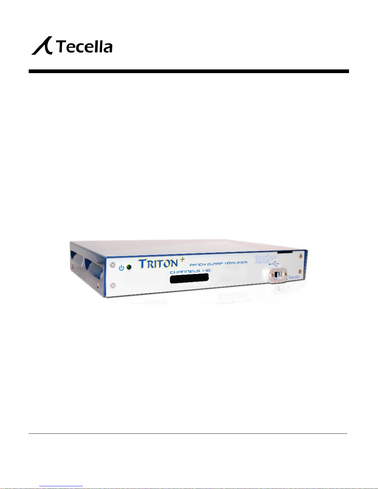
The Triton+ is a full-featured whole cell patch clamp amplifier, available in 1, 2, 4, or 8 channel
configurations. The digitizer, the head stages, and the model cells are all integrated inside the
Triton+ amplifier simplifying setup of the work environment. Triton+ communicates to the
computer via a standard USB 2.0 cable, so no special hardware is required on the computer.
1.2 Package Contents
Please confirm that the following items were included in the Triton+ package.
Triton+ amplifier
Power supply
USB cable (Mini-USB)
What You May Need To Provide
Since AC outlets vary depending on your country, you may need to provide your own
AC chord to connect between the power supply and the AC outlet.
1.4 Computer Requirements
The following is the minimum computer requirements for using the Triton+.
2GHz single core processor or 1.4GHz dual core processor
1GB RAM
10GB free space on your Hard Drive
One available USB 2.0 port
Windows XP, Vista, or 7
1.5 Installation Overview
The Triton+ setup can be summarized in the following 5 steps.
1. Install Driver file
2. Install Software
3. Plug in power supply
4. Plug in USB cable
5. Turn on the amplifier to associate Driver with the amplifier
These steps will be explained in greater detail in the following two chapters.
Page 5
4
Chapter
2
Installation
2.1 Select the Driver Setup File for Your OS
Before plugging in the amplifier to the computer for the first time, please follow the following
steps to install the FrontPanel driver file onto your computer. The FrontPanel driver file comes
in 32-bit version and 64-bit version. Please install the correct version that matches your
operating system (OS). You can check which version OS you are running by opening Control
Panels and selecting System. If you do not see any mention of 64-bit Operating System, then
please choose the 32-bit driver file.
Previous Driver Installations
If you have previously installed the FrontPanel driver onto your computer, there is no
need to reinstall the driver file, and you can skip this section and the next section on
FrontPanel driver file installation.
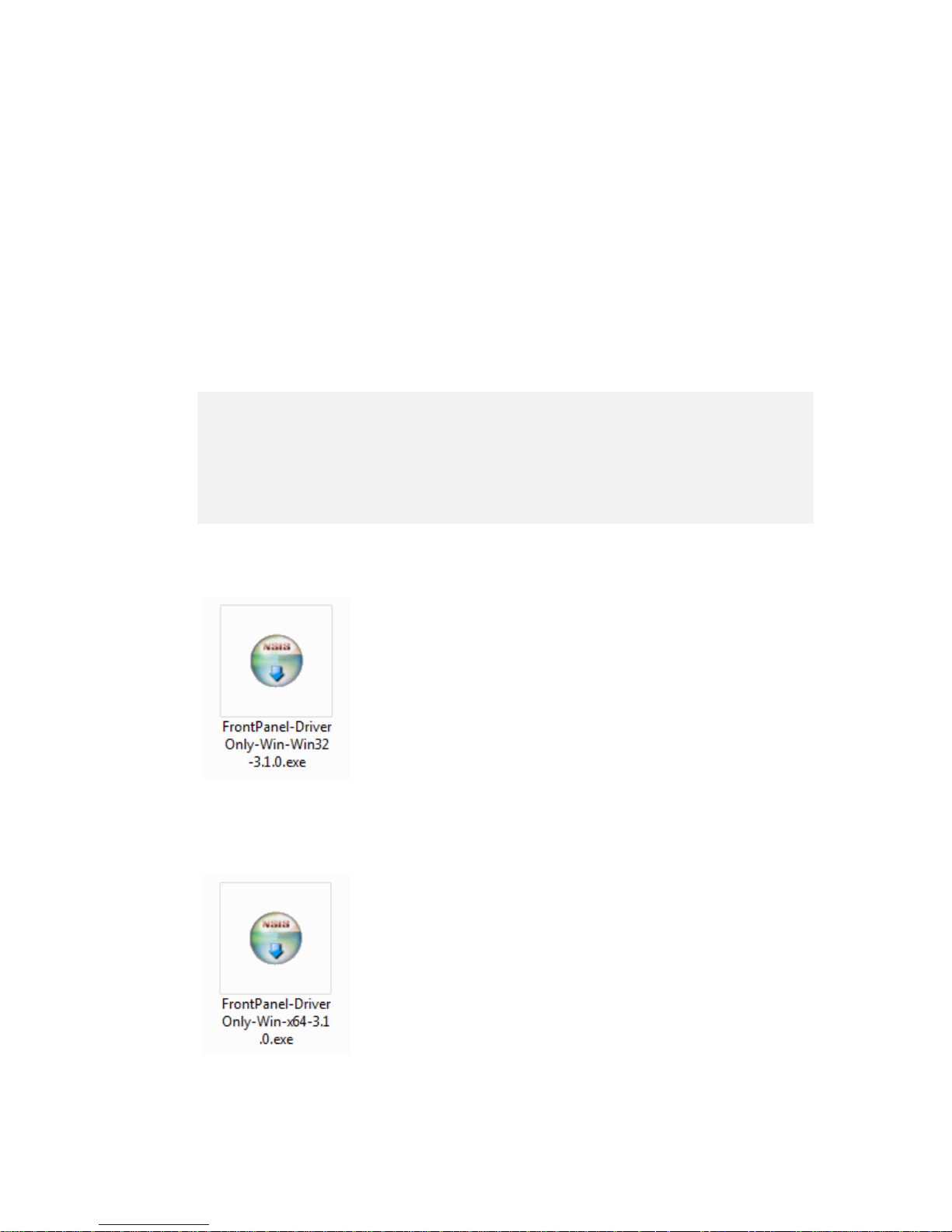
Driver Setup File for 32-bit Windows XP, Vista, 7
For 32-bit Windows XP, Vista, or 7 OS, please use the file called
“FrontPanel-DriverOnly-Win-Win32-3.1.0.exe”. Double click on the
icon to begin installing the driver files.
Driver Setup File for 64-bit Windows XP, Vista, 7
For 64-bit Windows XP, Vista, or 7 OS, please use the file called
“FrontPanel-DriverOnly-Win-x64-3.1.0.exe”. Double cli ck on the i con
to begin installing the driver files.
Page 6
5
2.2 Install Driver File Onto Your Computer
Follow the steps below to install the FrontPanel driver file onto your computer.
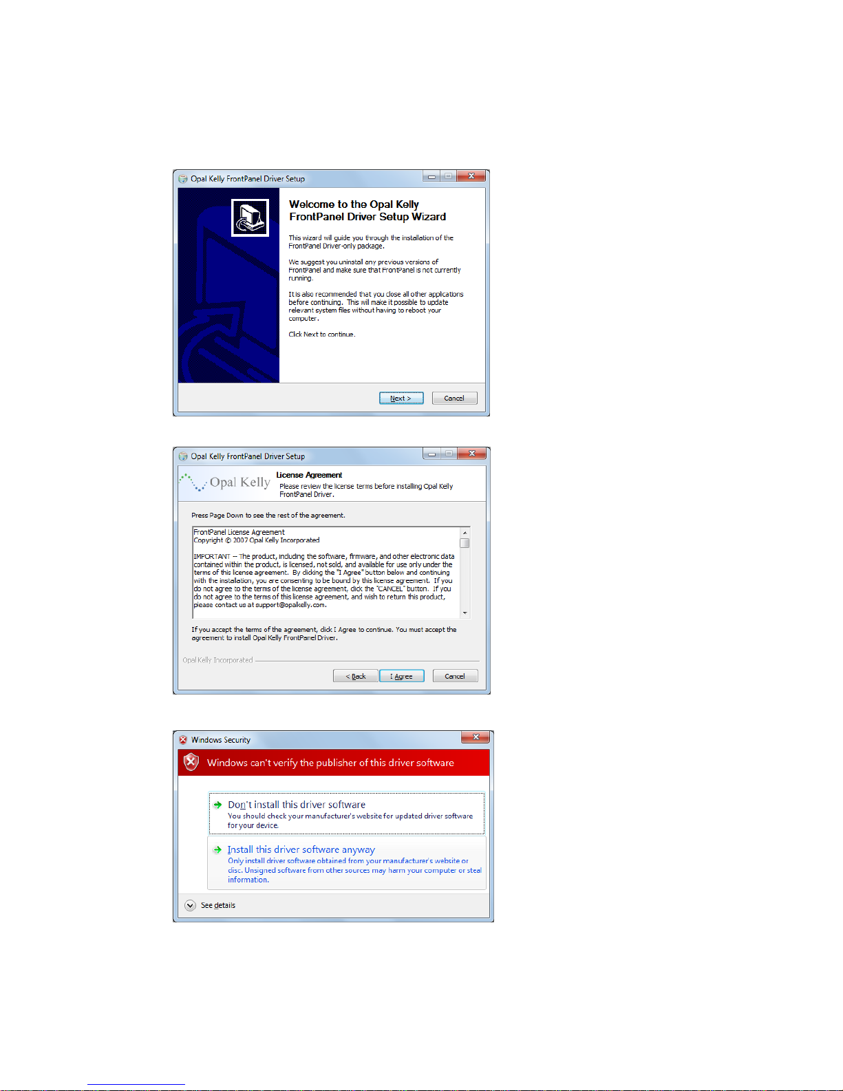
First, you will see the Setup Wizard
welcome screen. Click on “Next” to
proceed.
Next, you will see Opal Kelly’s
License Agreement. Click on “I
Agree” to install the driver.
Depending on the security setting of
your computer, you may see this
warning screen. Click on “Install thi s
driver software anyway” to continue
with installation.
Page 7
6
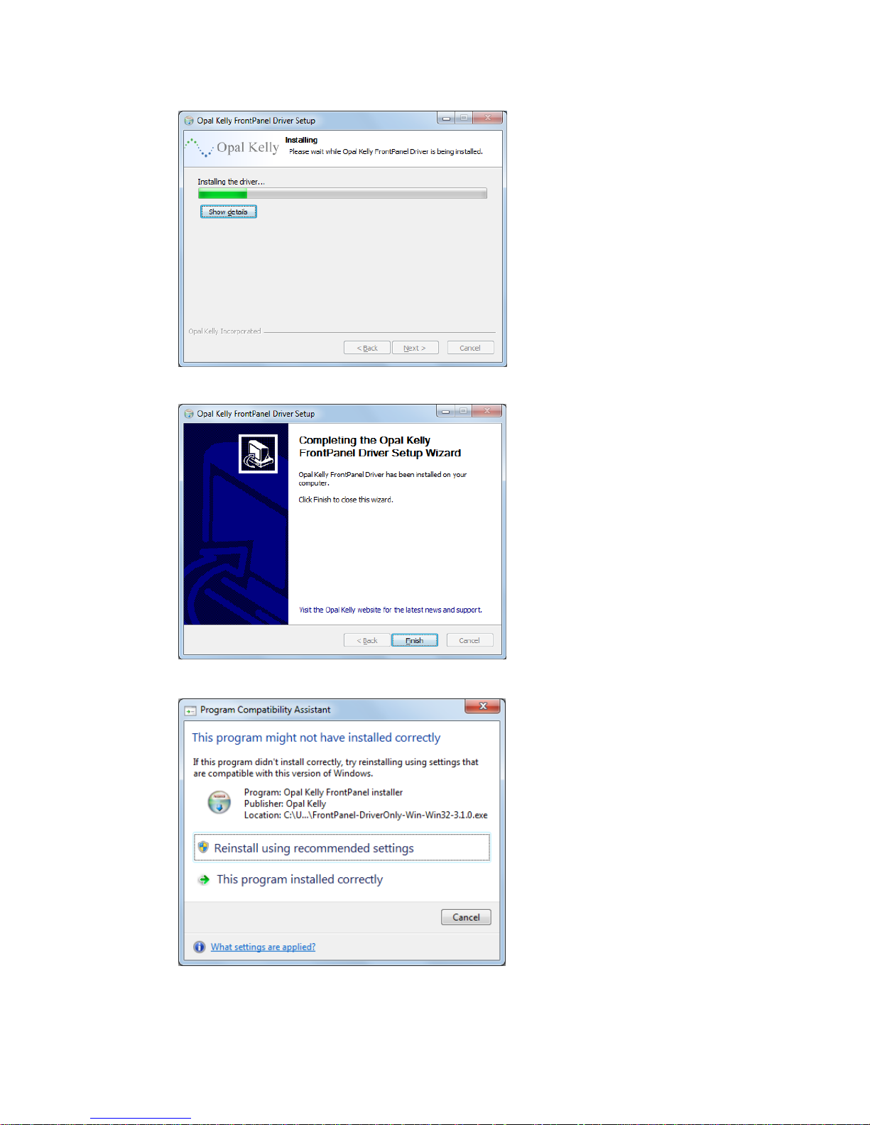
This screen may momentarily
appear during driver installation.
After the FrontPanel driver files has
been successfully installed on your
computer, you will see this
confirmation screen. Click on
“Finish” to exit the installation.
Although the driver files have been
installed on your computer, they
have not been associated with the
amplifier yet. The driver file and the
amplifier will be associated the first
time the amplifier is connected to the
computer and turned on.
This warning screen may appear on
computers running Windows Vista
and Windows 7, even if the
installation was successful. Click on
“Cancel” to exit the warning screen.
Page 8
7
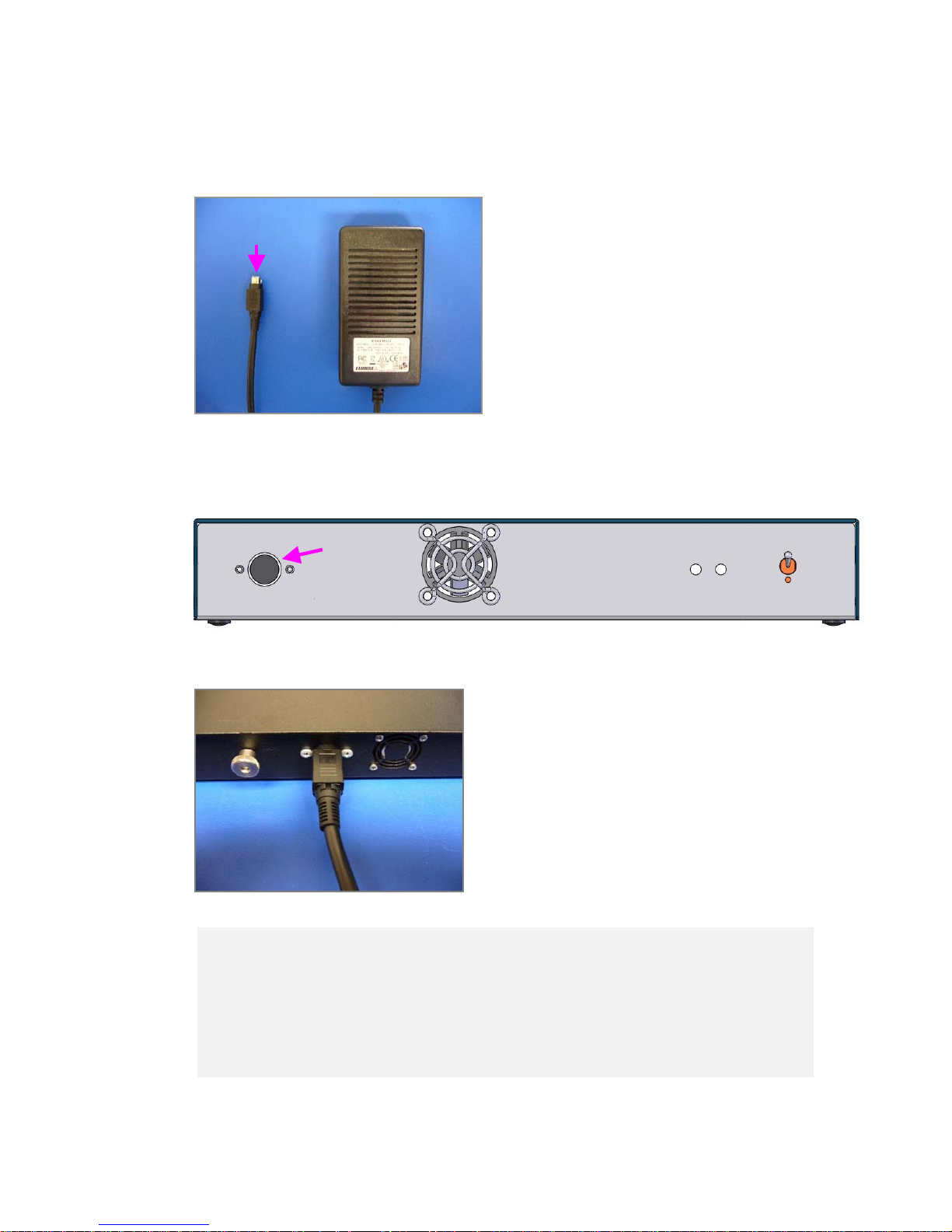
2.3 Connect the Pow er Supply T o the Amplifier
Power
Connector
Locate the power jack on the back of the amplifier as indicated by the arrow below.
Locate the connector of the power supply.
Power
Jack
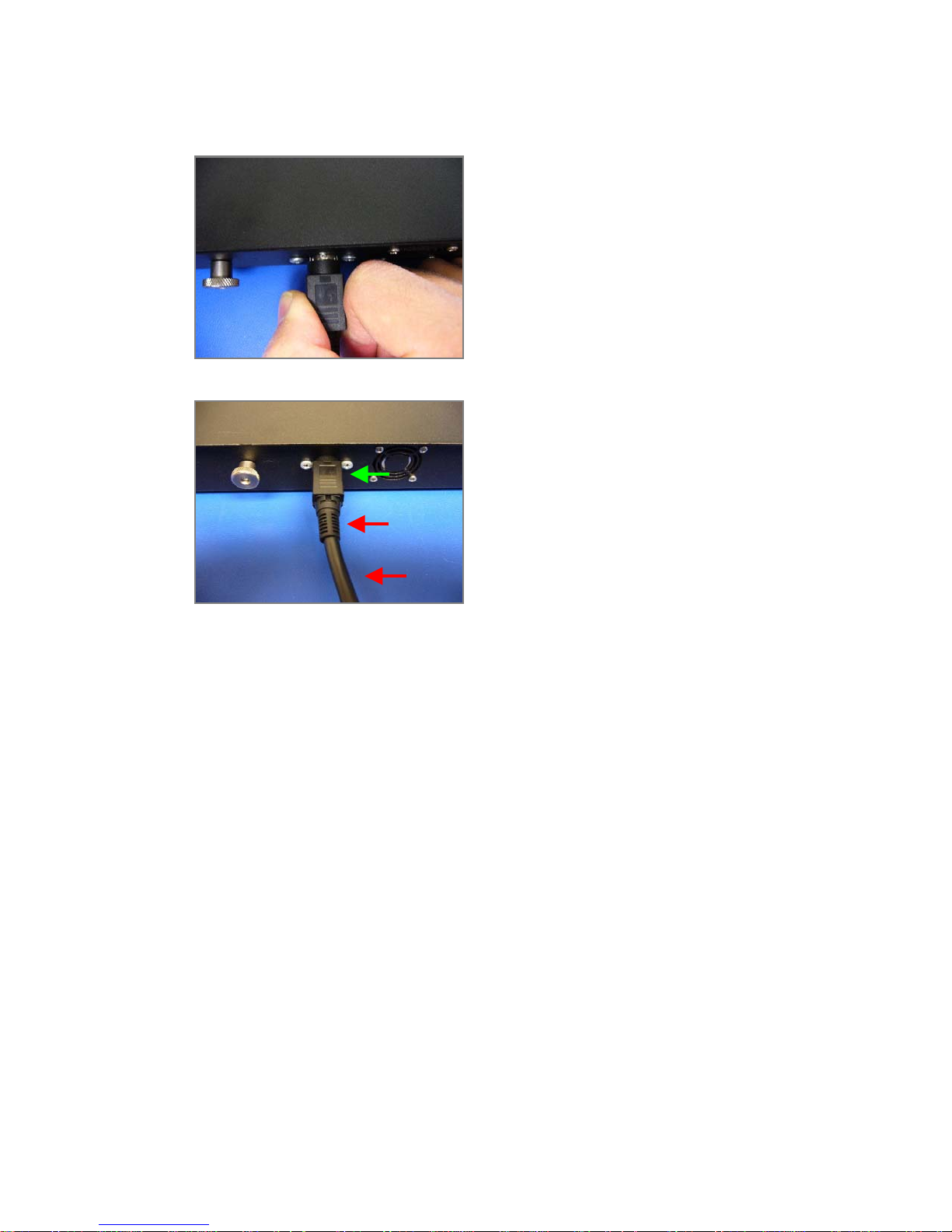
Test for Proper Insertion
Insert the power connector firmly into the power
jack. The power connector has a locking
mechanism, so it is important that the power
connector is fully inserted into the power jack.
Considerable force is required to properly insert the power connector and engage the
locking mechanism. To test for proper insertion, pull snugly on the cable. If the
connector gets loose, the insertion force was insufficient to lock the connector. Please
try again by applying more insertion force.
Page 9
8
Caution! Extremely Important When Detaching Power Cable
When detaching the power cable from the
amplifier, in order to disengage the locking
mechanism, you must first pull back on the
connector cover as shown.
As you pull back on the connector cover, the silver
colored shield should become visible. Continue
pulling on the connector to detach the power cable.
NEVER attempt to detach the power connector by
pulling on the cable or on the stress relief of the
cable.
YES
NO !
NO !
2.4 Plug In the Powe r Supply Into an AC Outlet
Plug in the power supply into an AC outlet using the appropriate AC chord for your country’s
outlet.
Page 10
9
2.5 Connect the USB Cable T o the Amplifier and the Computer
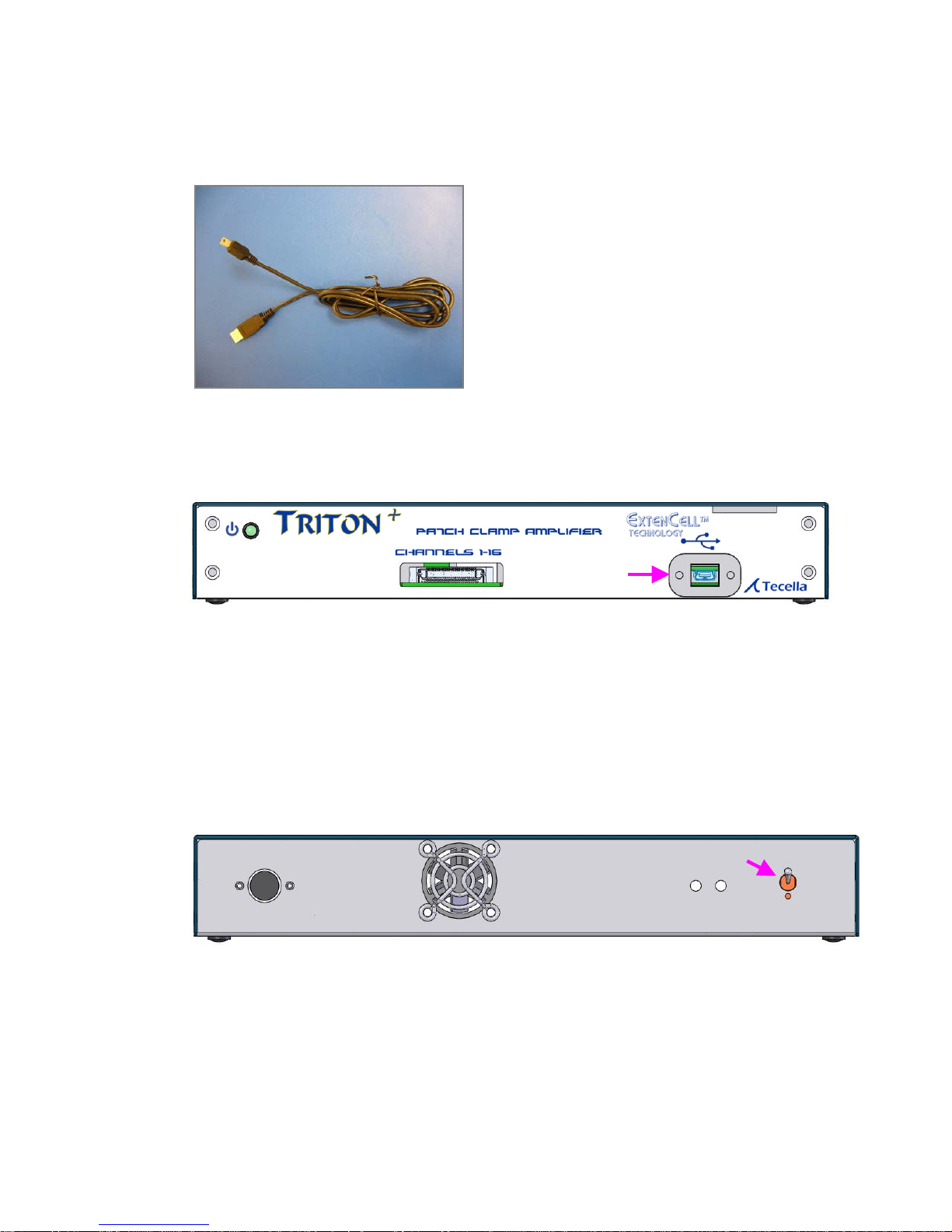
A standard Mini-USB cable (as shown) is included
with the amplifier.
Plug the small end of the USB cable into the USB port of the amplifier indicated below.
Plug the large end of the USB cable into the USB port of your computer. The USB port must
be USB 2.0.
2.6 Tu rn On the Amplifier
Turn on the amplifier by toggling the power switch indicated below.
USB
Power
Switch
Page 11
0
2.7 Associating the Driver and the Amplifier (Windows XP)
Automatic Association On Windows Vista and Windows 7
Windows Vista and Windows 7 will automatically associate the FrontPanel driver and
the amplifier. No further action is required.
For Windows XP computers, please proceed with the following steps.
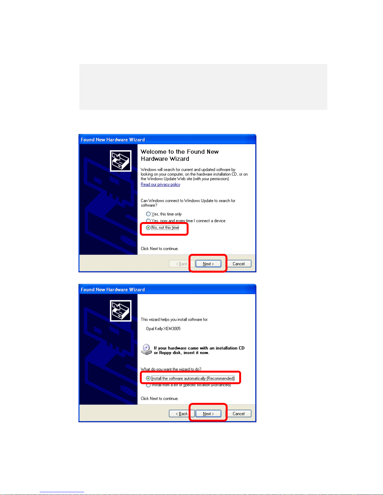
The first time you
connect the amplifier to
your computer, “Found
New Hardware Wizard”
will launch, and you will
see this screen. Select
“No, not this time”, and
click “Next”.
Select “Install the
software automatically”,
and click “Next”.
1
Page 12
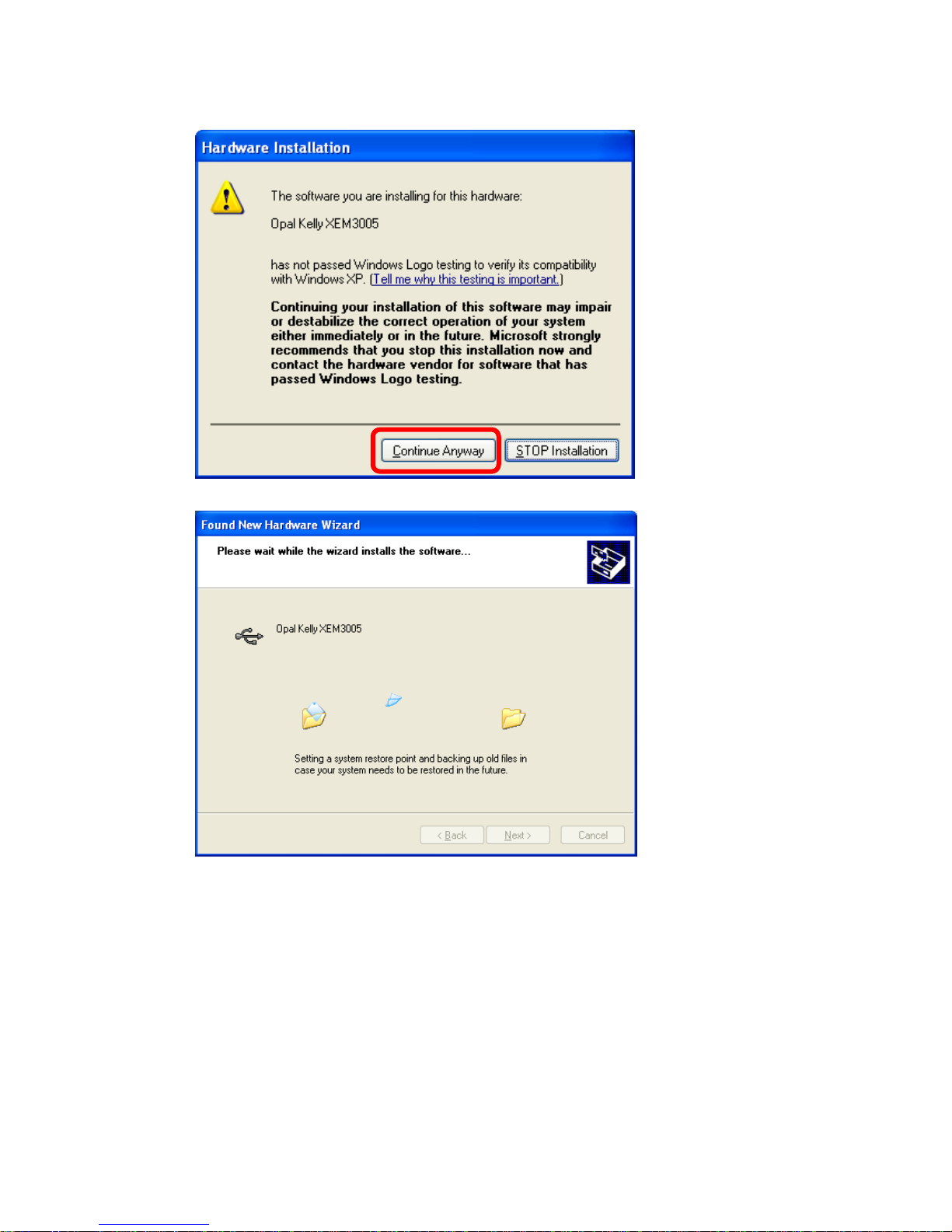
If this screen pops up,
click on “Continue
Anyway”.
You will see this screen
as the amplifier gets
installed on your
computer.
11
Page 13
2
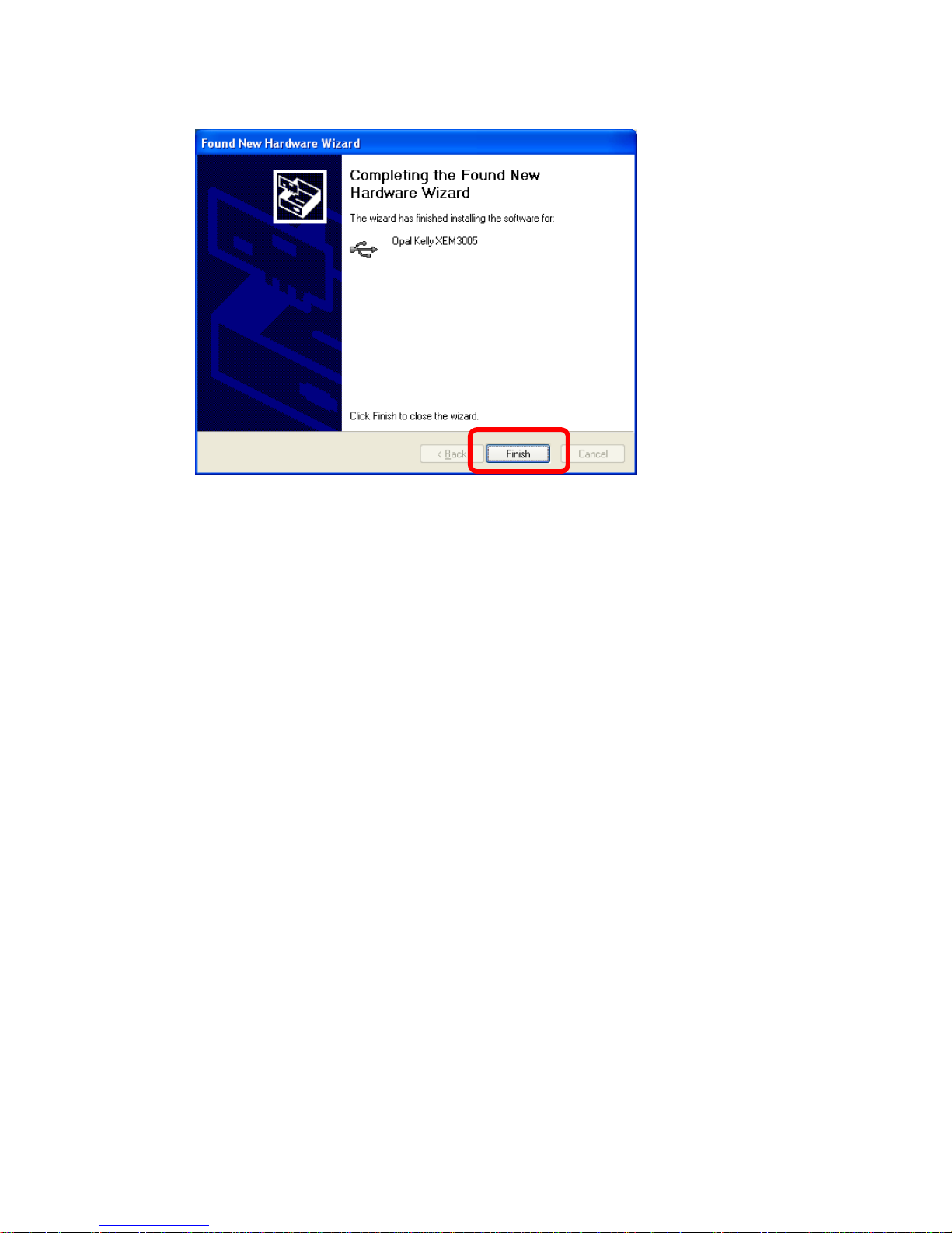
The amplifier is now ready for use.
You will see the
following after the
amplifier finishes
installing. Click “Finish”
to exit the wizard. You
are now ready to begin
using the amplifier.
1
Page 14
3
Chapter
3
Getting Started With TecellaLab
Now that the amplifier has been installed, the following steps will help you get familiar with the
amplifier quickly using the TecellaLab software.
WinWCP Users
If you wish to use the WinWCP software, please jump to the next chapter.
3.1 Install TecellaLab
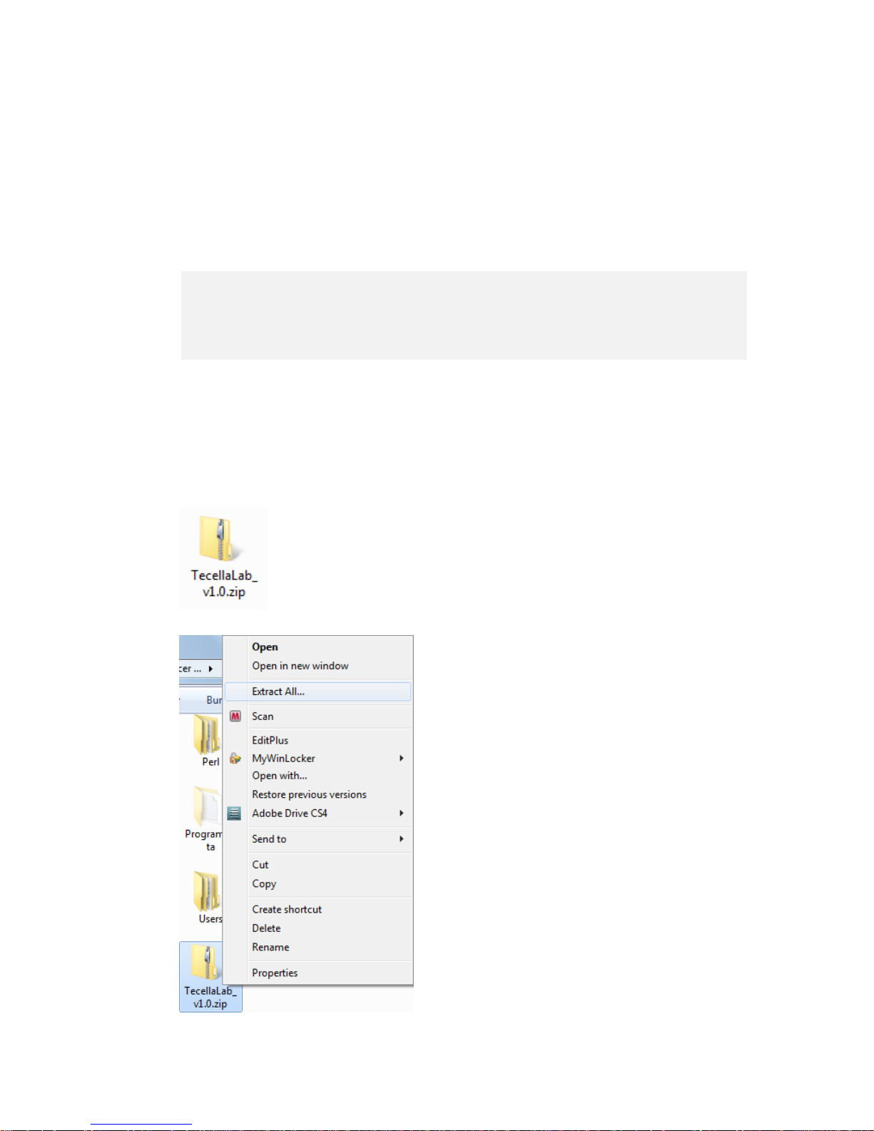
TecellaLab can be installed on your computer by simply unzipping the software zip file to a
desired folder on your computer.
Unzip TecellaLab To Folder
Please locate the TecellaLabxxx.zip file provided to you via CD, via download
from our website, or via email attachment from us.
Right click on the zip file and select “Extract All…”.
1
Page 15
4
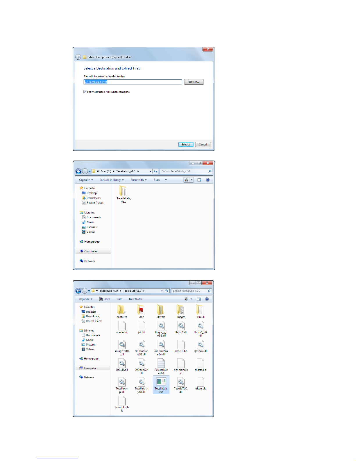
We recommend you extract the
files to the root folder of your main
drive, usually the C:\ folder,
because data recordings are
saved to a subfolder of the
TecellaLab folder by default.
Double click on the TecellaLab
folder.
You will see TecellaLab.exe file
which is the TecellaLab software.
You will also see several folders,
including “captures” which stores
the data, “stimuli” which stores the
stimulus command protocols, and
“doc” which contains TecellaLab
documentation.
1
Page 16
5
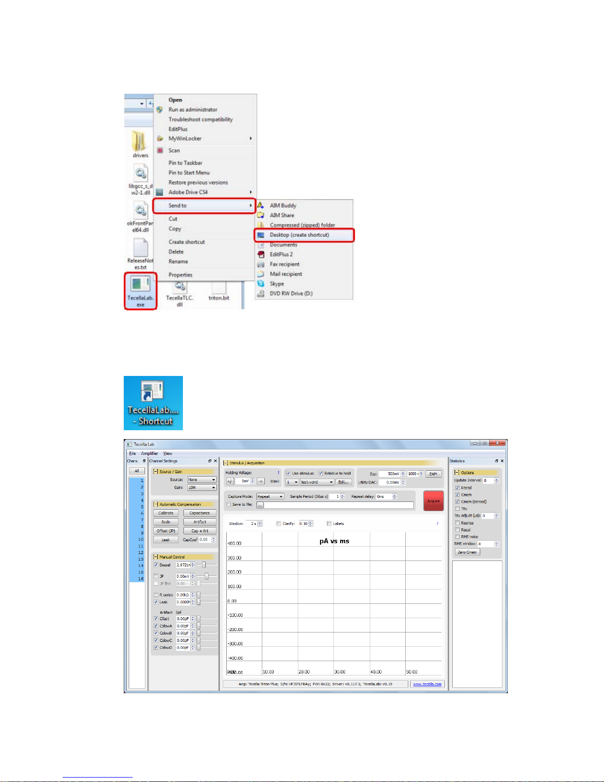
Create a Desktop Icon
For ease of access, we recommend
you create a desktop icon. To do so,
right click on the TecellaLab.exe
icon, then choose Send To and then
Desktop.
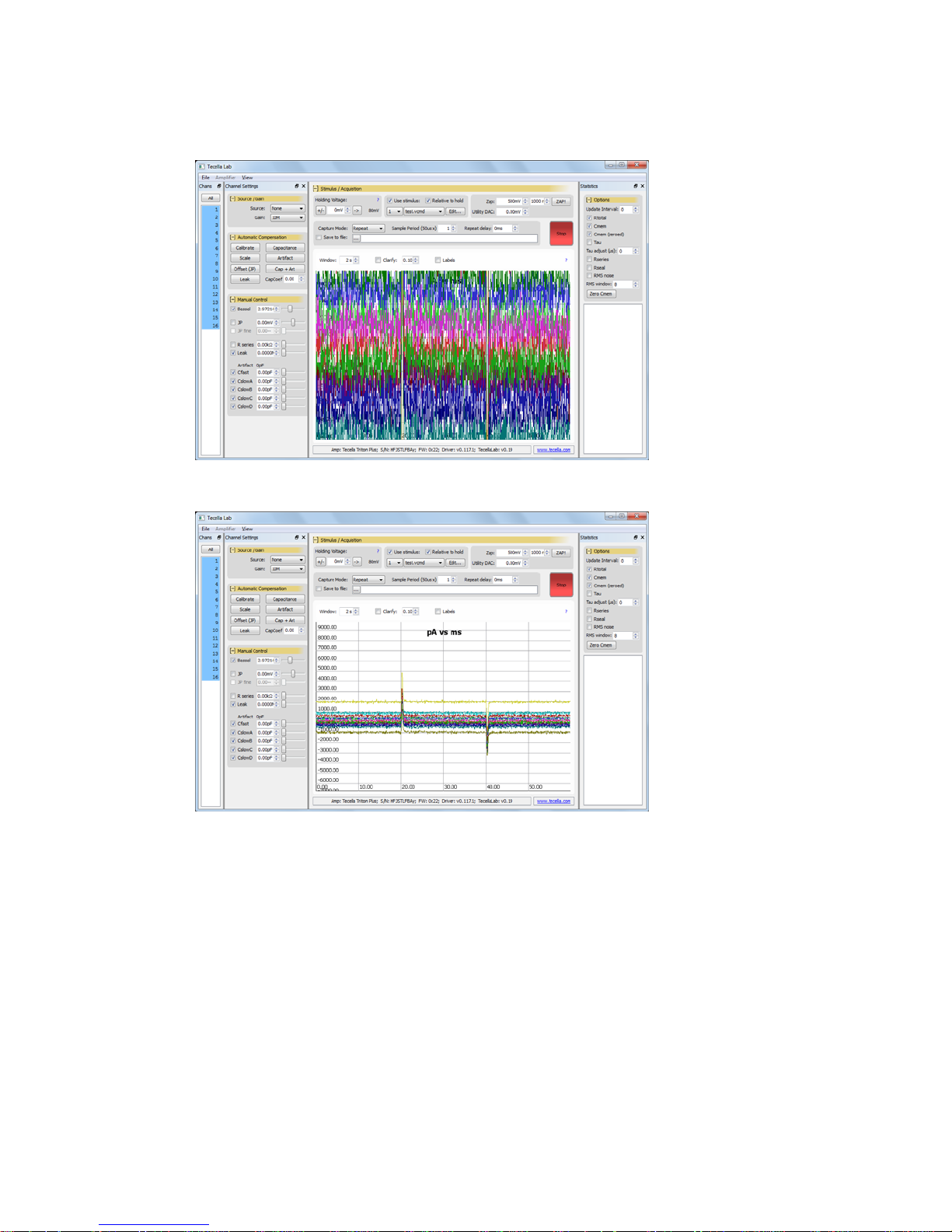
3.2 Launch TecellaLab
Start TecellaLab by double clicking on the Desktop icon you just created. If
you did not create a desktop icon, then you can start TecellaLab, by double
clicking on the TecellaLab icon in the TecellaLab folder that you created.
Screen below will appear.
1
Page 17
6
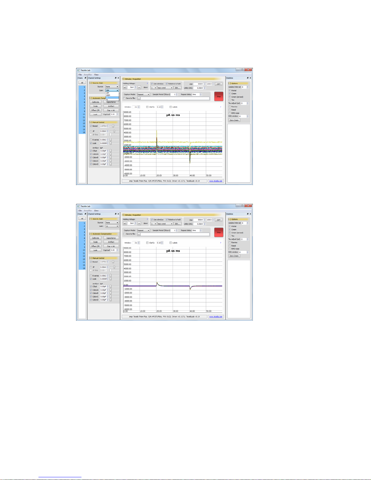
3.3 Start Acquisition
Click on the Acquire
button in the upper
right to begin
acquisition. You
should see a
waveform like this.
Double Click in the
waveform section to
zoom out and fit the
waveform.
You can now see the
entire waveform.
Holding down the left
mouse button allows
you to move the
waveform. Holding
down the right mouse
button allows you to
zoom in and out.
1
Page 18
7
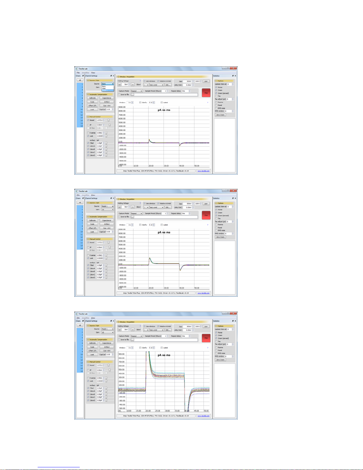
3.4 Changing Gain (Rf setting)
Pull down on the Gain
menu and select 1Gig.
Notice the substantial
reduction in noise at
the higher gain.
1
Page 19
8
3.5 Changing Source
Pull down on the Source
menu and select Model.
The Triton+ comes
equipped with a whole celll
model cell on every
channel. The model cell
consistsw of 10Meg series
resistance and 100Meg
seal resistance.
Notice the current flowing
through the model cell.
Holding down on the right
mouse key, move the
mouse up, then to the right
to zoom in on the vertical
and horizontal axes,
respectively.
1
Page 20
9
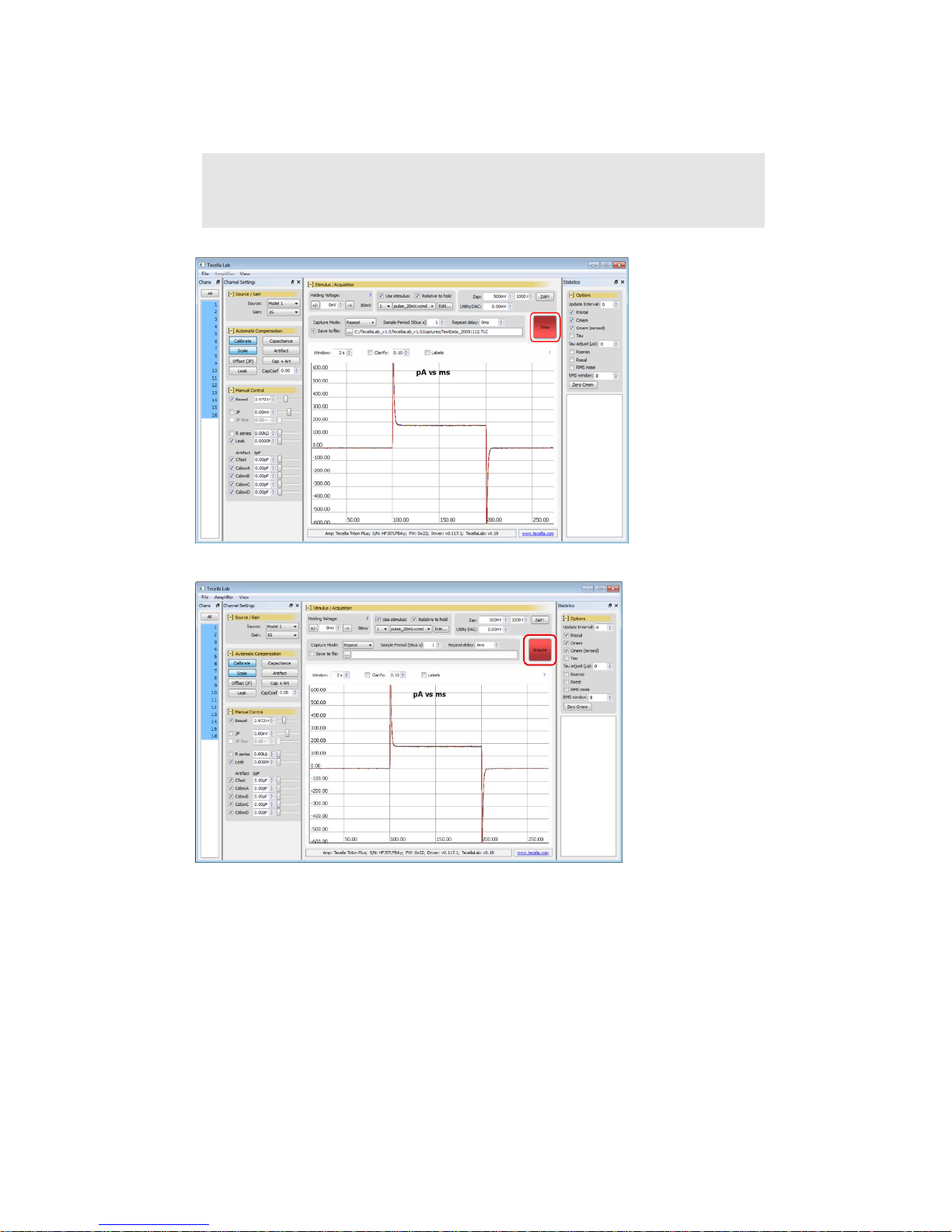
3.8 Sav e Data To a File
Warning!
Make sure acquisition is stopped before proceeding.
If the Acquisition/Stop
button is displaying “Stop”,
then you are in
acquisition mode. Stop
the acquisition by
pressing on the “Stop”
button.
You can now proceed to specify the output file.
When acquisition is
stopped, the button should
display “Acquire”.
1
Page 21
0
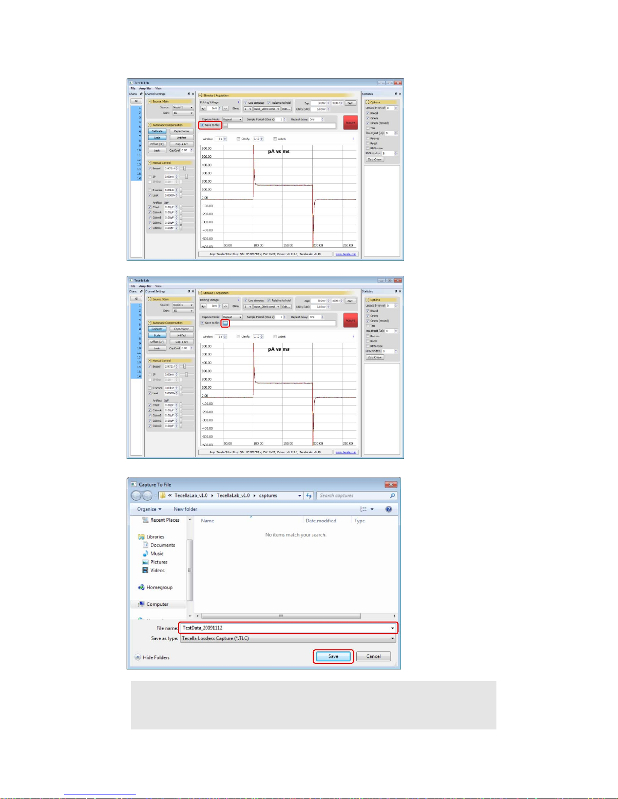
Click on “Save to file”.
Click on “…” to specify the
output file.
The “Capture To File”
dialog box will pop up. The
default output folder is
“captures” under the
TecellaLab folder.
Type in the output file
name.
Click on “Save” to set the
output file name and exit
the dialog box.
Data is saved in TLC (Tecella Lossless Compression) format with file extension of TLC.
TLC files can be converted to tab-delimited, ATF format using the tlc2atf.exe utility.
2
Page 22
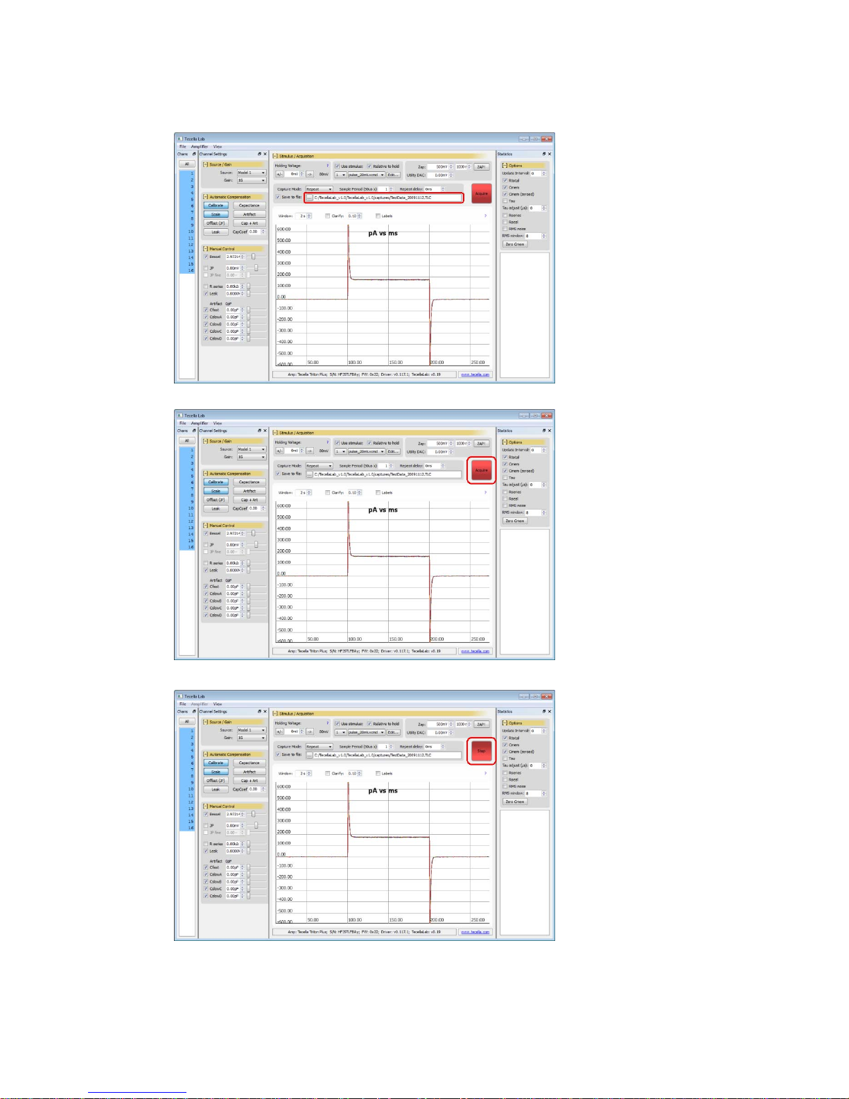
The output file name is
displayed in TecellaLab.
Acquisition data will now
be saved to this file.
Click on “Acquire” to begin
acquiring data and saving
it to the output file.
Click on “Stop” to stop
acquisition and to write the
data to the output file.
Subsequent starting and
stopping of acquisition will
cause the data to be
appended to the output file.
21
Page 23
2
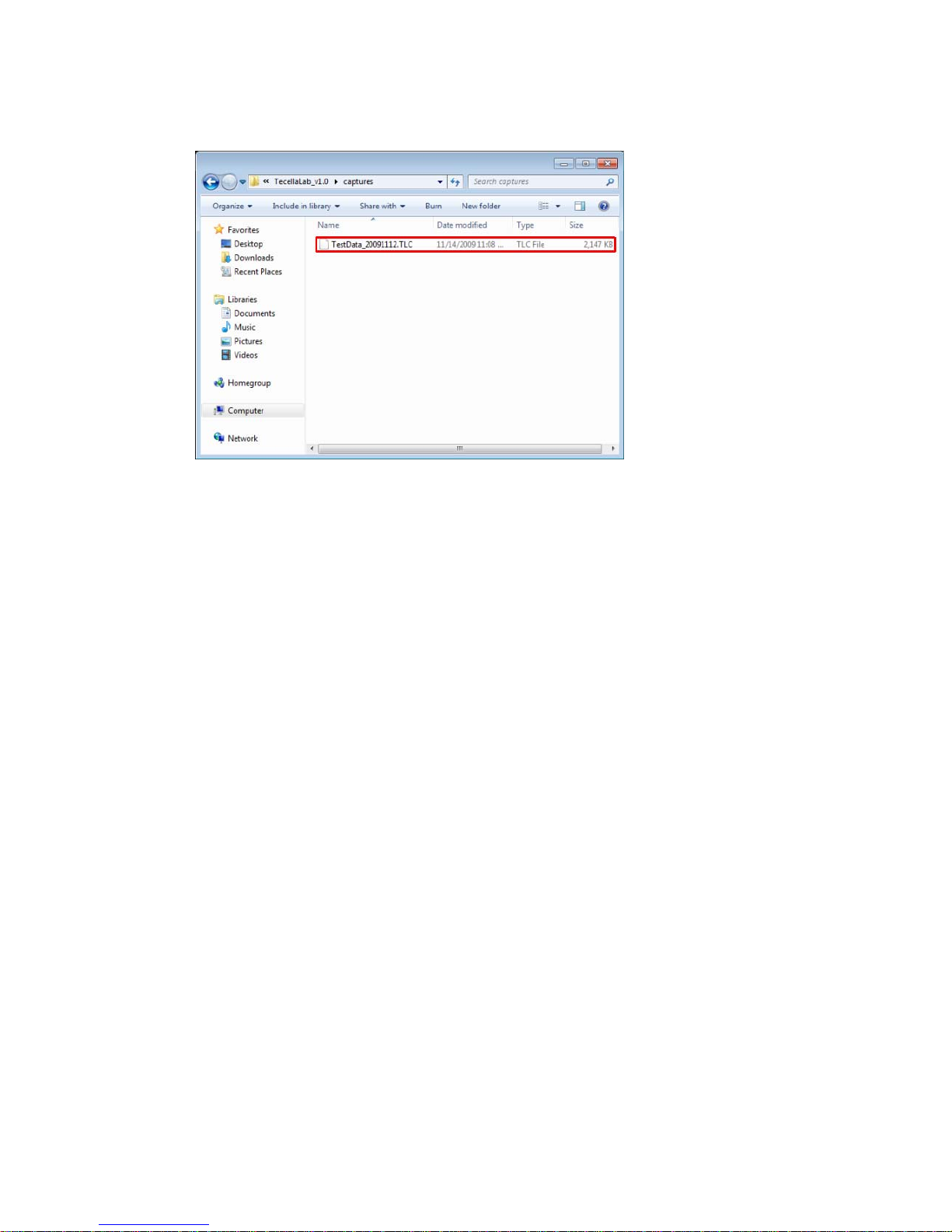
Go to the “captures” folder
in your TecellaLab folder
to access the captured
data.
3.9 Con vert Data to T ab Delimited or A TF F ormat
Click on the Start button to begin acquisition. You should see a waveform like this.
3.10 Using TecellaLab
For additional detailed information on the use of TecellaLab, please refer to the chapter titled
“Using TecellaLab”.
2
Page 24

3
2
Page 25

4
Chapter
4
Getting Started With WinWCP
WinWCP is a full featured 3
amplifiers.
rd
Party software application that works with Tecella’s Triton+
4.1 Download WinWCP Setup File
First, go to the following web site.
http://spider.science.strath.ac.uk/sipbs/page.php?show=software_ses
Download the WinWCP software, by clicking on the link that says:
WinWCP Vx.x.x Setup File
(x.x.x represents the version number that is currently available for download.)
4.2 Download WinWCP User Guide
From the same web site, download the WinWCP User Guide, by clicking on the link that says:
WINWCP User Guide.pdf
4.3 Install WinWCP
To install WinWCP on your computer, double click on WinWCP_Vx.x.x_Setup.exe that you
downloaded in the previous step.
Follow the setup wizard to complete the installation.
4.4 Start WinWCP
Locate the WinWCP icon on your computer’s Desktop, and double click on the
icon to start WinWCP.
2
Page 26
5
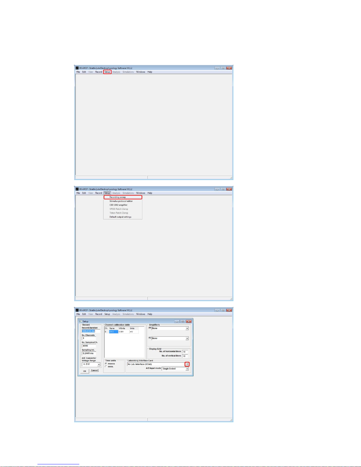
4.5 Set Laboratory Interface Card to “T ecella T riton”
Click on “Setup” in the top
menu.
Select “Recording sweep”.
Click on the pull-down
menu under “Laboratory
Interface Card”.
2
Page 27
6
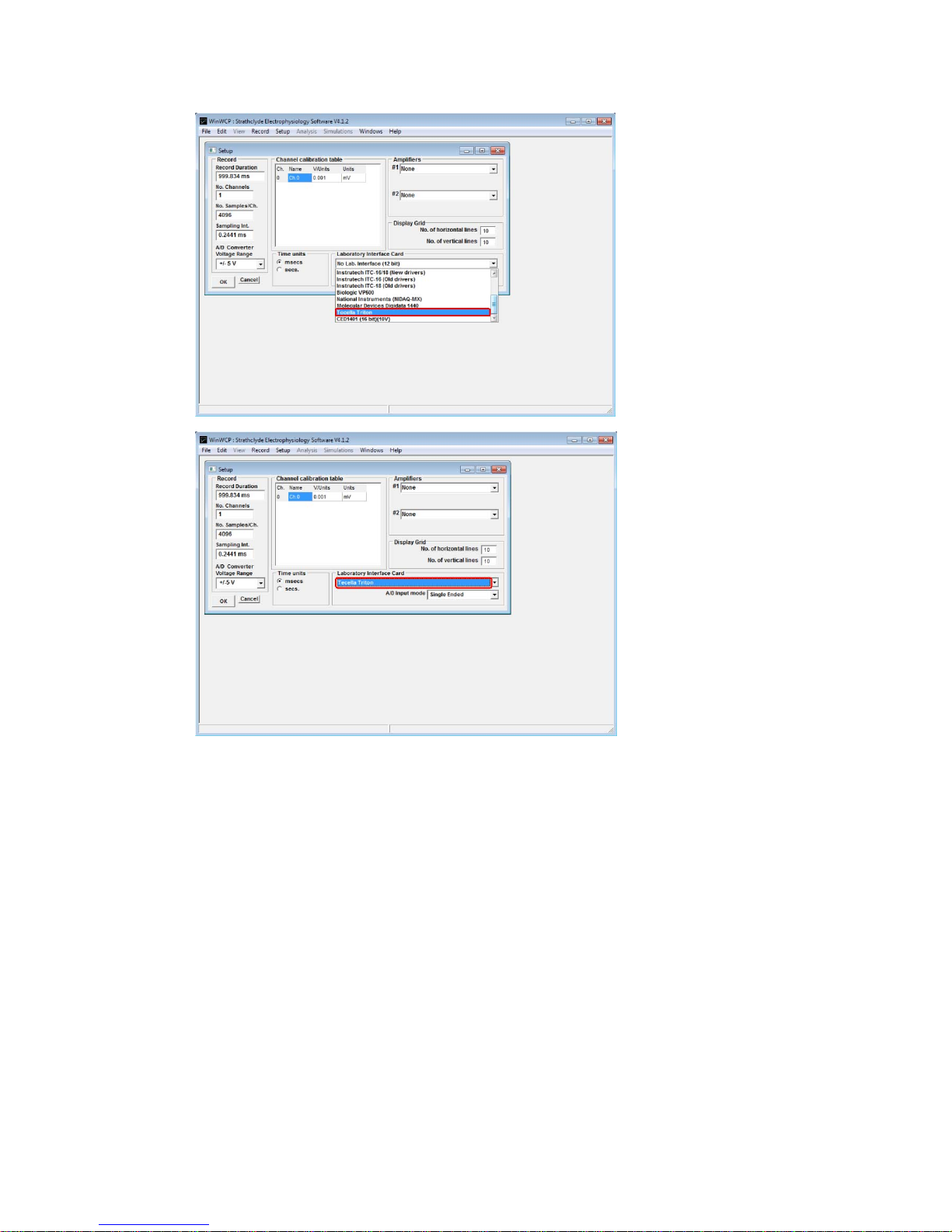
Select “Tecella Triton”.
Tecella Triton has been
selected. You are now
ready to use WinWCP with
the Triton+.
4.3 Using WinWCP
For information on how to use WinWCP, please refer to the WinWCP User Guide that you
downloaded previously.
2
Page 28

7
Chapter
5
Connecting To Your Setup
2
Page 29

8
Chapter
6
Using TecellaLab
2
Page 30

9
Chapter
7
Hardware Calibration
The hardware is automatically calibrated every time TecellaLab or WinWCP is started.
Under normal use, there should not be any need to re-calibrate the hardware.
However, if you suspect that the hardware calibration has drifted, due to heat, as an
example, the hardware can be recalibrated with TecellaLab or by closing and re-starting
your application, either TecellaLab or WinWCP.
The following steps describe how to check whether your hardware is out of calibration, and if
so, how to perform re-calibration.
6.1 Check For Hardware Drift
Select “Test Pulse” stimulus.
Select “All” channels.
Select “Model” as source.
Start “Acquire”.
Baseline should read 0pA, and the middle section should read about 180pA. If you see
significant deviation from these values, then proceed with the following steps to re-calibrate the
hardware.
6.2 Option 1: Re-start the Application
If the situation permits, closing and re-starting your application, either TecellaLab or WinWCP,
will automatically re-calibrate the hardware.
If the situation does not permit you to close your application, and if you are ru nning Tecella Lab,
please proceed with the following steps.
2
Page 31
0
6.3 Option 2: Re-run Hardware Calibration
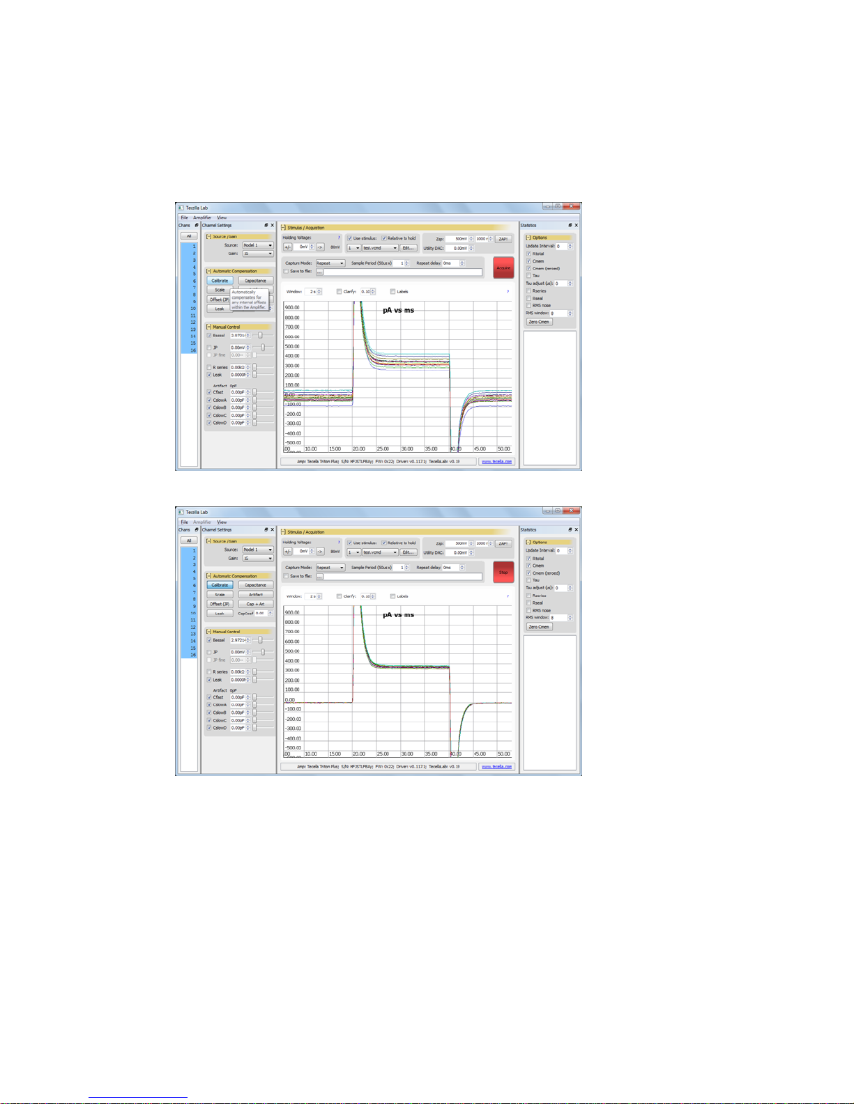
Calibrate Internal Offset
Click on the “Calibrate”
button to compensate
for internal amplifier
offsets.
Notice that the
baseline offsets have
now been removed.
3
Page 32
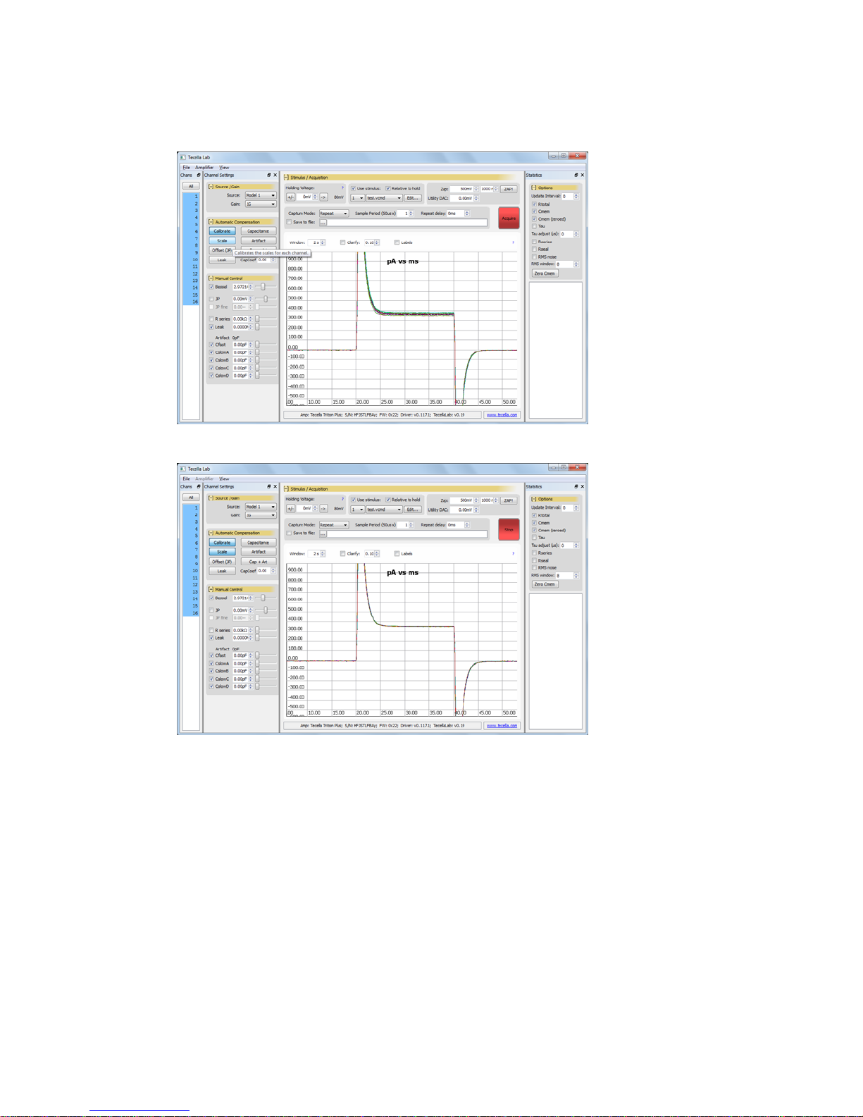
Calibrate Scale
Click on the “Scale”
button to properly
scale the Rf gain
resistors.
Notice that the
currents through the
model cells have been
scaled uniformly
across all channels.
31
Page 33
2
Chapter
8
Specifications
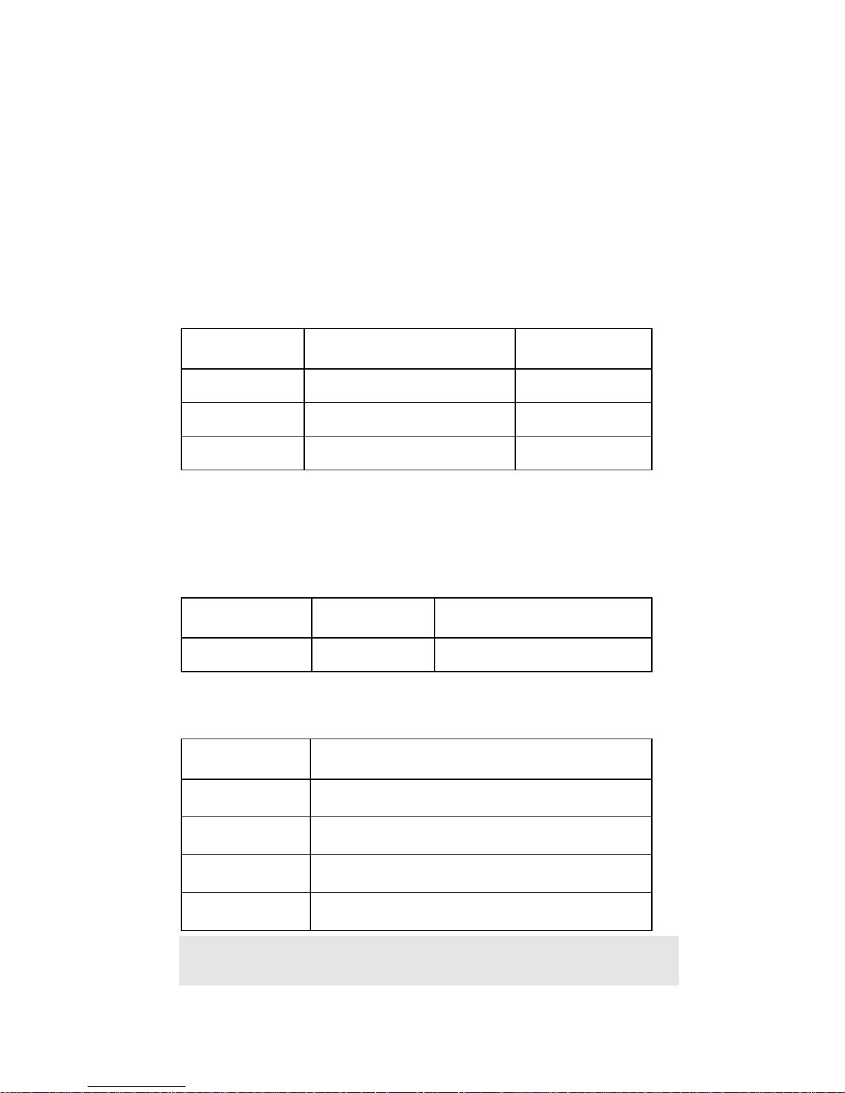
8.1 Source Selector
The connection to the input of the amplifier is determined by the Source Selector, and the
following choices are available. Source Selector also determines whether the attached
external object is being clamped by the amplifier.
Source Selector can be controlled independently for each channel.
Source Connection Is External Object
Clamped?
None (open) Nothing is connected to the input of
the amplifier.
Head (normal) External object is connected to the
input of the amplifier.
Model Cell Internal model cell is connected to the
input of the amplifier.
No
Yes
No
8.2 Headstage and Feedbac k Gain Resistor (Rf)
Each amplifier channel comes equipped with an independent headstage integrated inside the
amplifier. Each headstage supports up to 4 feedback gain resisto rs (Rf) for varying the gai n on
the input signal.
# of Headstages # of Feedback
Gain Resistors
1 per Channel 4 per Channel Yes, as long as Source is set to Head
The following table lists the available Feedback Gain Resistor values, and example
applications for each value.
Feedback Gain
Resistor (Rf)
10Meg Ohm Bath.
100Meg Ohm Population patch clamp, multi-cell patch clamp.
1Gig Ohm Whole cell patch clamp.
5Gig Ohm Bilayer.
Note: Feedback Gain Resistor (Rf) values can be customized prior to purchase or after
purchase, for an additional fee.
Example Application
For measuring pipette resistance or hole resistance.
Loose seal.
Bilayer.
Single channel.
Continuous Clamping
(normal).
3
Page 34
3
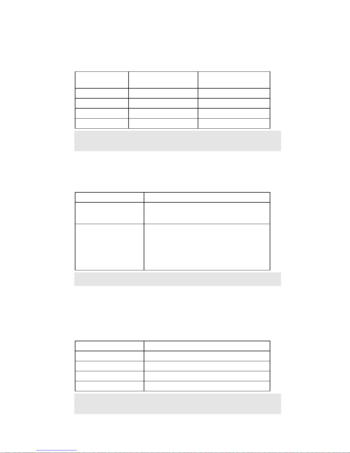
8.3 Current Range & Current Resolution
Values for measurable current range and current resolution are listed in the following table,
and are dependent on the selected Feedback Gain Resistor (Rf).
Feedback Gain
Resistor (Rf)
10Meg Ohm
100Meg Ohm
1Gig Ohm
5Gig Ohm
Note: Feedback Gain Resistor (Rf) values can be customized prior to purchase or after
purchase, for an additional fee.
Current Range Current Resolution
±450nA
±45nA
±4.5nA
±900pA
8.4 A/D Resolution & Sampling Ra te
Triton+ is equipped with a high-performance internal digitizer. The digitizer performance is
listed below
Parameter Value
A/D Resolution Internal resolution is 18-bits.
Acquisition Data is stored with 16-bit resolution. The
two LSB (least significant bits) are discarded.
Sampling Rate 20kHz
10kHz
5kHz
3.33kHz
2kHz
1kHz
15.3pA
1.53pA
0.153pA (153fA)
30.5fA
Note: Other sampling rates can be provided for a customization fee.
8.5 Analog Filter
Each channel is equipped with a 6-pole low pass filter implemented in analog circuit to
preserve data integrity. The filter characteristics are listed in the following table. Although the
analog filter can be programmed beyond 100kHz, the amplifier bandwidth will be limi ted by t he
selected Feedback Gain Resistor and the A/D sampling rate.
Parameter Value
# of Filters Independent analog filter per channel
# of Poles 6
Filter Type Bessel (Thompson)
Frequency Range 800Hz to 160kHz
Note: Butterworth or Chebyshev filters can be provided for an additional fee. Frequency
Range can be shifted for an additional fee.
3
Page 35
4
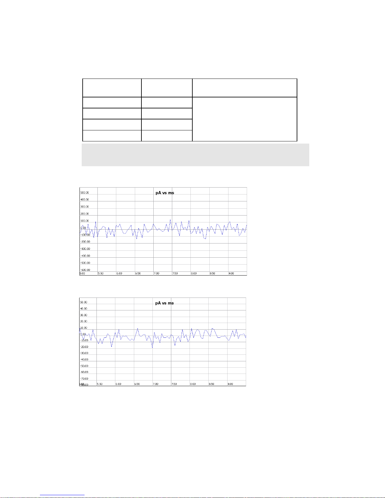
8.6 Noise
Noise level is dependent on the selected Feedback Gain Resistor (Rf), and the values are
listed in the following table.
Feedback Gain
Resistor (Rf)
10Meg Ohm 65pA
100Meg Ohm 7pA
1Gig Ohm 0.8pA
5Gig Ohm 0.2pA
Note: Feedback Gain Resistor (Rf) values can be customized prior to purchase or after
purchase, for an additional fee.
RMS Noise
(typical)
Conditions
Source: None
Filter: 3kHz
Vcmd: 0mV
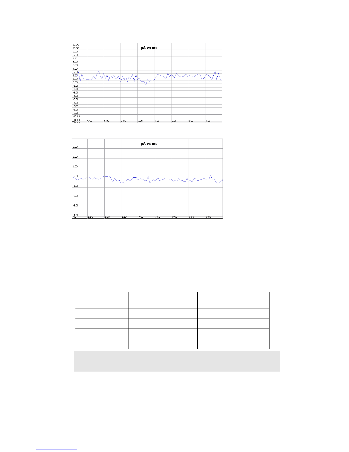
Typical noise profiles for each of the Feedback Gain Resistor (Rf) settings appear below.
Rf = 10Meg
RMS Noise = 65pA
M
Rf = 100Meg
RMS Noise = 7pA
3
Page 36
5
Rf = 1Gig
RMS Noise = 0.8pA
Rf = 5Gig
RMS Noise = 0.2pA
8.7 Capacitance Compensation
The Triton+ provides 1 Fast Capacitance (Cfast) and 3 Slow Capacitance (Cslow)
compensation circuits. Cfast comp ensation is typically us ed to compensate capaci tive spikes
created by capacitance in the cable, chip, and at the input to the headstage. Cslow
compensation is typically used to compensate capacitive spikes created by membrane
capacitance.
Compensation
Circuit
Cfast 0.1us 0 to 200pF
Cslow1 20us 0 to 100pF
Cslow2 100us 0 to 100pF
Cslow3 200us 0 to 100pF
Note: Capacitance Compensation circuits can be customized prior to purchase or after
purchase, for an additional fee.
Time Constant Compensation Range
3
Page 37
6
8.8 Series Resistance Compensa tion
The Triton+ provides Series Resistance compensation circuit on every channel.
Parameter Value
Range 0 to 20Meg ohm
Note: Series Resistance Compensation circuits can be customized prior to purchase or
after purchase, for an additional fee.
8.9 Analog Leak Compensation (optional)
The Triton+ provides an optional Analog Leak Compensation circuit. The Analog Leak
Compensation circuit is designed to properly scale the compensation current based on the
applied clamping voltage.
Parameter Value
Range 0 to 2Meg ohm
Note: Analog Leak Compensation circuits is an optional feature available on the –L
models. This option can be ordered at the time of purchase, or added after
purchase for an additional fee.
8.10 Command Voltage
Stimulus or Command Voltage specification is listed below.
Parameter Value
Range
Resolution 0.5mV
Note: Command Voltage circuit can be customized prior to purchase or after purchase,
for an additional fee.
8.11 Holding Voltage
Holding Voltage specification is listed below
Parameter Value
Range
Resolution 0.5mV
Note: The sum of holding voltage and command voltage must be within ±255mV.
±255mV
±255mV absolute
3
Page 38
7
8.12 Junction Offset Compensation
Junction Offset specification is listed below.
Parameter Value
Range
Resolution 0.1mV
Note: Junction Offset circuit can be customized prior to purchase or after purchase, for
an additional fee.
±255mV
8.13 Zap
Zap specification is listed below.
Parameter Value
Range
Resolution 8mV
Note: Zap circuit can be customized prior to purchase or after purchase, for an additional
fee.
±1000mV
8.14 Sync Out
8.15 Trigger In
8.16 Acquisition Modes
8.17 Acquisition Data Format
8.18 Power Supply
8.19 Power Requirements
8.20 Mechanical Dimensions
3
Page 39

8
Chapter
9
Troubleshooting & Support
T echnical Support
Please contact Tecella for technical support at::
Email: [email protected]
Phone: +1-714-641-1709
Fax: +1-714-641-1569
Mail: Tecella
3001 Red Hill Ave, Suite 1-204
Costa Mesa, CA 92626
USA
3
 Loading...