

Page 1
510 v7
520 v7
TECHNICAL MANUAL
For smart cars & smart car holders
Immobilizer –
heart of auto-theft
protection sistem
Page 2

2
TEC- 61201-1 Technical Manualе PRIZRAK-510, 520 v7
Description of the securit y system
Introduction
Differences between security systems:
• PR IZR A K-510 – wire engine locking
• PR IZR A K-520 – wireless engine locking.
Functions of the Immobilizer:
• Protecting the vehicle from being stolen or hijacked
• Alert if the vehicle was tampered with
Integrator (www.tec-integrator.com) contains information about
compatibility of the Immobilizer with a specific vehicle, and a list of
vehicles compatible with the Immobilizer and specific features.
Ter m s
Programming button — one of the factory (default) buttons, with
which the Immobilizer can be programmed (buttons specific to the
vehicle can be found in the Integrator). Programmable button can be
changed only within short time after installation of the Immobilizer.
Also built in button can be used as programming button. (please see
“Immobilizer wiring diagram”).
Security — is a state of the Immobilizer, which is turned on after
locking the doors in any way provided by the manufacturer of the
vehicle (keyless entry system, remote control, rearming the alarm
etc.) and turning factory security system. Secure state can be left
by unlocking the doors with the original remote control or vehicles
keyless access system or by entering the PIN code.
Speed control allows setting the locking activation algorithm for
Immobilizer and AntiHiJack features. Speed control can be activated
and de-activated in user settings programming menu. Certain vehicles
may not support this feature (please see Integrator for details).
Guard mode — active state of the PINTODrive® and AntiHiJack: if
one of these functions has entered guard mode, to leave it it is required
pass authentication procedure, otherwise engine will be locked.
Comfort feature — feature allowing not only to lock doors from the
factory remote, but also to raise windows (sunroof also can be closed).
Immobilizer feature
Immobilizer is a feature designed to prevent vehicle from being
stolen from parking space. PINTODrive® goes into effect if ignition
was switched off for more than 3 seconds. If PINTODrive® feature is
enabled and active it requires PIN code to be deactivated, otherwise
engine will be locked:
• Engine will be switched off on attempt to move if speed control
is enabled and supported by the vehicle
• The engine will be turned off within 5 seconds after the ignition
has been turned on if the Speed control is disabled or not supported
by the vehicle.
AntiHiJack feature
AntiHiJack is the function that prevents the vehicle from being
hijacked or stolen from the parking area. AntiHiJack enters the Guard
mode in the following cases:
• The ignition was turned off for longer than 3 seconds
(including a case when Immobilizer is off; if the Immobilizer
was switched on, the Immobilizer will follow its algorithms)
• The driver’s door was opened.
Upon entering the Guard mode, AntiHiJack feature goes through a
series of phases, and in case if the Guard mode was not deactivated,
the feature will activate the engine lock.
Phases change only when the ignition is on. When the ignition has
been turned off, the Immobilizer saves the current condition, and will
continue the feature operation when the ignition is back on.
The Guard mode of the AntiHiJack feature can be deactivated at
any step by entering the PIN code.
The Guard mode phases are as follows:
•
Idle phase
•
Warning phase
•
Locking phase
Idle phase.
In this phase AntiHiJack follows two different algorithms
depending on the availability of Speed control. If the Speed control is
available, AntiHiJack waits until the vehicle covers a set distance from
the moment of Guard mode activation Upon that, AntiHiJack goes into
the Warning phase. If the Speed control is not available, Idle phase
consists of three stages:
• Waiting for the driver’s door to be closed
• Waiting for preset amount of brake presses to be made
• Pause before going to warning phase.
Warning phase consists of two steps:
• Warning the driver with the trill that they have to enter PIN
code.
• Warning other drivers on the road of the possible hazardous
situation due to the upcoming engine locking (10 seconds). It
is carried out by vehicle hazard lights. Driver warning is still on.
Locking phase.
The engine lock is activated, the siren is turned
on, and the hazard lights are activated. The siren and hazard lights
will switch off in 15 seconds. AntiHiJack will be in locking phase until a
new PIN code verification.
If «Safe stop» is enabled engine will be locked only if speed is
lower then 30 km/h or on complete stop (depends on the settings of
the safe stop).
Table of Content
s
Description of the Immobilizer .......................................................... 2
Introduction ....................................................................................... 2
Ter m s ................................................................................................. 2
Immobilizer feature ............................................................................. 2
AntiHiJack feature ............................................................................... 2
PIN code entering sequence ................................................................ 3
PUK code ............................................................................................ 3
Maintenance mode .............................................................................. 3
Automatic deactivation of Maintenance mode ....................................... 3
Other options ..................................................................................... 3
Connection .......................................................................................... 4
Tab l e1 Assignment of immobilizer connector pins ................................. 4
Immobilizer pin connectors’ description ............................................... 4
pL in e-221 description and installation guidelines .................................. 4
Tab l e 2 Relay outputs description ........................................................ 4
Immobilizer programming ............................................................. 5
Stage 1. Immobilizer interfacing with vehicle ........................................ 5
Stage 2. Immobilizer configuration programming .................................. 6
Tab l e3 Programming menu .................................................................. 6
Menu 1 Hardware settings configuration .............................................. 6
Menu 1.2 Configuration of programmable inputs / outputs .................... 6
Tab l e 4 Immobilizer Programmable Output Functions ............................ 7
Tab l e5 Immobilizer Programmable Input Functions ............................... 7
User Set tings Configuration ................................................................. 9
Menu 2. User settings ......................................................................... 9
Changing PIN code ............................................................................. 9
Reassigning Programming Button ........................................................ 9
Examples of programming ................................................................. 10
Reset ting to factory default settings .................................................. 10
Immobilizer wiring diagram ............................................................... 11
Immobilizer units arrangement in the vehicle ............................... 12
Standard scope of delivery .............................................................. 13
Specifications and operating conditions ........................................ 13
Table of contents
Description of the Immobilizer
Page 3
3
TEC- 61201-1 Technical Manualе PRIZRAK-510, 520 v7
Accelerator pedal lock (force to stop)
Feature will stop the vehicle if AntiHiJack was triggered minding
safe lock settings. Vehicle has to support «speed control». At the eng
of the warning phase, if speed of the vehicel didn’t increase within 5
seconds or brake pedal was pressed within 3 seconds, lock will activate
for 2 seconds, then it will be lifted for 5 seconds. This will be repeated
5 times. Every repetition lock lift will be reduced for 1 second. On fifth
repetition lock will be permanent.
PIN code entry sequence
• Turn on the ignition or start the engine
• Enter PIN code
• Wait for the confirming trill.
Available PIN options
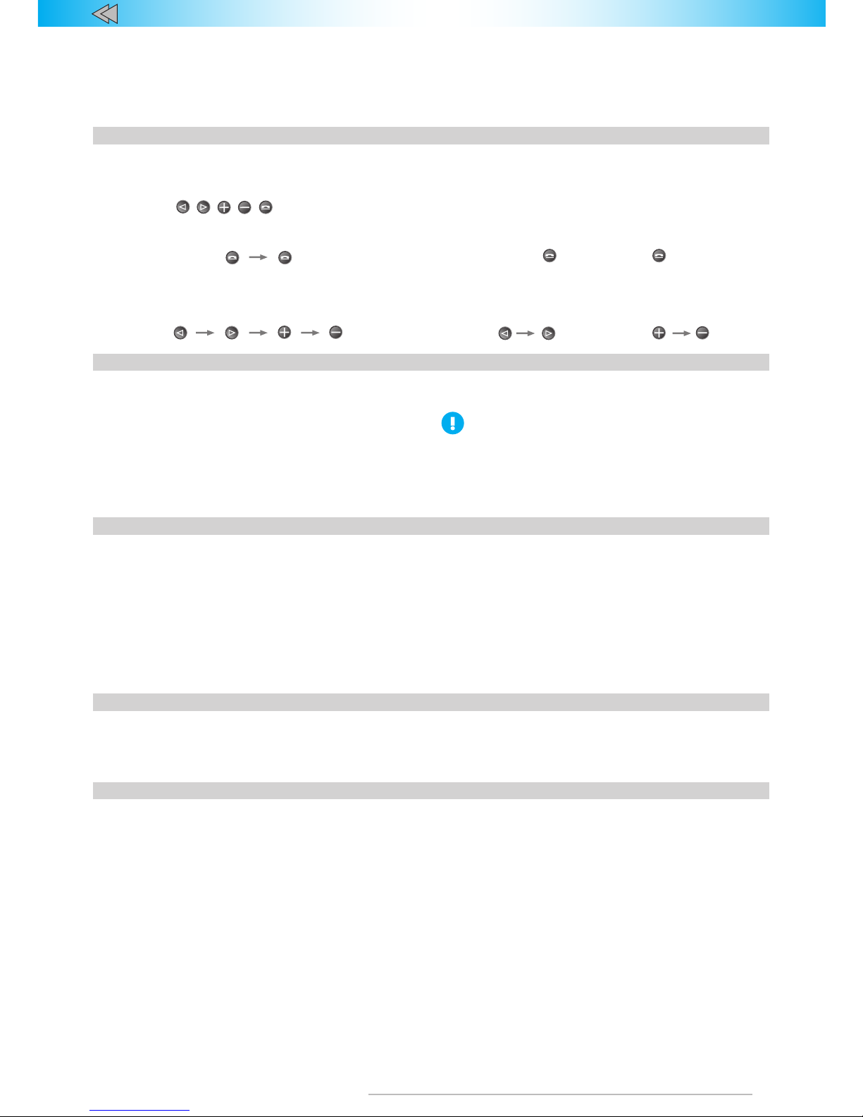
Buttons , , , , are used here as an example. Request the list of avaliable buttons in your vehicle at your shop.
One-digit PIN: Two-digit PIN:
~2 second pause
Single-button PIN entry
When entering the PIN code keep in mind the entering sequence.
One-digit PIN: Two-digit PIN:
~2 second pause
PUK code
PUK code - 4-digit numbers under the scrach layer on the plastic
card that came with the Alarm. PUK-code will disable all security
features of the alarm. Use PUK-code only if you lost PIN-code.
After PUK code is entered, all security functions of the Alarm will be
deactivated regardless the selected authentication method.
PUK code can be found under the scratch layer on the plastic card.
• The factory set PIN code is «2»; it is entered by using
the Programming button (please check the Integrator).
• You can not assign a PIN-code «1» - one press of the
one button
PUK-c ode entry
PUK code is entered by the Programming button with a 2 second pause in between keystrokes.
Entering se quence:
• Turn on the ignition or start the engine
• Enter PUK code
• Wait for the confirming trill.
Maintenance mode
Maintenance is an operation mode when all hijack protection and
service functions of the Alarm are temporarily disabled.
The Alarm will notify of activation of the Maintenance mode as
follows:
• When disarming, LED will turn on
• When the ignition is turned on, LED will go out
• Warning trill after PIN-code entry
• After the ignition is turned of f, LED will light up and will be on
for a while.
To activate or deactivate the Maintenance mode follow these
steps:
1. Tur n off the ignition.
2. Enter PIN code.
3. Press the Programming button 6 times (you should start within
10 seconds after verification).
4. Wait for confirmation of your actions:
• If the Maintenance mode is on, the system will emit 1
audio signal, 1 light signal and a trill
• If the Maintenance mode is off, the system will emit 2
audio signals, 2 light signals and a trill.
Automatic deactivation of the Maintenance mode
This function automatically disables the Maintenance mode after
a 10 km run. So even if you forget to disable this mode in the service
station, it will still be automatically disabled.
If Maintenance mode is activated by PUK code, it cannot be
automatically disabled.
If the vehicle does not support Speed control, automatic
deactivation of this feature will not be avaliable.
Other options
Immobilizer has several options to make your vehicle more
comfortable and secure.
Automatic window roll up
The system can be programmed so that the vehicle windows are
rolled up when engaging the lock.
Setting the electromechanical hood lock
You can install an optional (third- pa rty) hood lock and program
the Immobilizer to lock the hood when locking the vehicle, and
open it only after enter PIN code.
Central lock control
If your vehicle does not have an integrated door lock activated
when driving (locking) or turning off the ignition (unlocking), this
option can be provided by the Immobilizer.
Page 4
4
TEC- 61201-1 Technical Manualе PRIZRAK-510, 520 v7
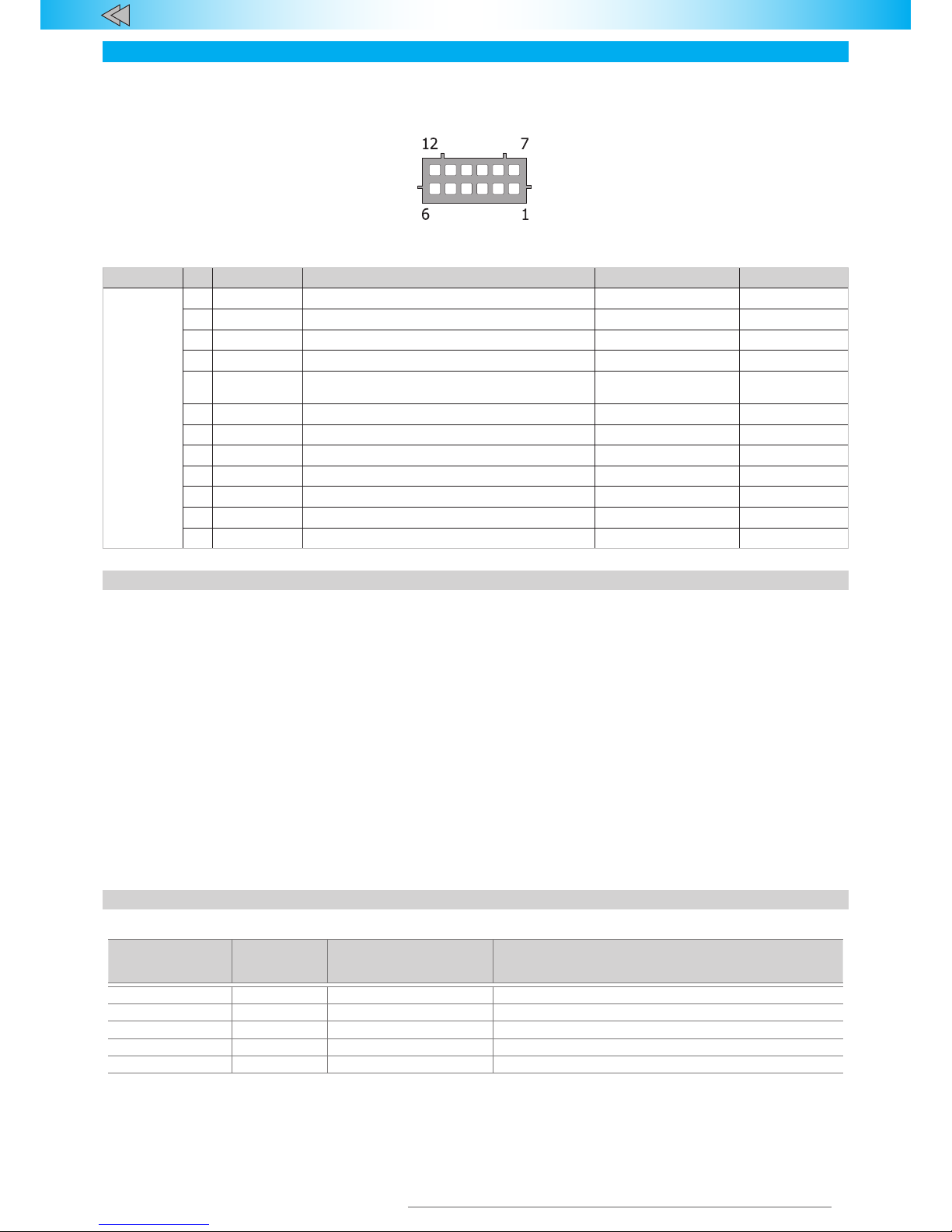
Immobilizer Inputs / Outputs functionalities are described in the Table 3. Connection pin numeration is indicated on fig. 1. Aside from
outputs with set functions Immobilizer is equipped with two programmable outputs each of which can be assigned with one of 20 functions
(see CAN bus adapter features table).These outputs are set for controlling an accessory hood lock. Output configuration is carried out via
programming (see Immobilizer hardware functions programming (Menu 1)).
Tab l e1. Assignment of immobilizer connector pins
Socket No. Color Function Type Current, m
12-pin 1 Pink/Green Brake lights condition control Programmable output (+) 1,5
2 White/black Engine locking/ Underhood unit control Output (-) 150
3 Brown CAN-L vehicle data bus CAN —
4 Brown/red CAN-H vehicle data bus CAN —
5 Blue/red Alternate hazard lights control/autentication impulse
(depending on the vehicle)
Programmable output
(+/-)
150
6 Black Power supply Ground —
7 Orange/white Closing of hood lock via HCU-230 Programmable intput (+) 1,5*
8 Yellow/red Connection in between the central unit and the relay Communication channel —
9 Green/black Control of position of a hood Programmable input (-) 50
10 Gray/yellow Analog button/Positive button Input (+) —
11 Gray/black Reference ground/Negative button Input (-) —
12 Red Power supply +12 V 1200/5**
Immobilizer pin connectors’ description
Pins No. 1.
Brake lights control. It is used only in cases when
vehicle CAN bus does not contain data on brake pedal position (see
Integrator files). In such cases input No. 1 is to be connected to brake
pedal terminal switch output. Should the CAN bus contain brake pedal
position data the input’s function is lost and can be restored only
when settings are reset to factory default ones.
Pin No. 2.
“Engine lock” is connected to one of relay coil con¬tacts,
which is used for engine operation or ignition lock. The output can be
set for controlling a normally-open or normally-closed relay. Alt
Pin No. 3 and 4.
“CAN-H and CAN-L vehicle data bus” are connected
to vehicle CAN bus (see “Integrator files”). Programmable negative
output (“Lock Impulse” by default).
Pin No. 5.
“Alternate hazard light control” is used for hazard light
controlling on vehicles where CAN bus control is not available. Please
see Integrator files software product for information on vehicle-specific
connection features.
Pin No. 6.
“Ground” is connected to vehicle body in one of the
loca¬tions determined by vehicle manufacturer for original equipment
ground connection.
Pin No. 7.
Closing of hood lock via HCU-230. Incoming impulse on
this input will lock hood lock via HCU-230. The function can used
when you install an immobilizer in conjunction with third party
equipment.
Pin No. 8.
“Communication channel” is connected to positive polarity
commutative voltage vehicle circuit that is used for communication
with main unit and locking relay. Upon installing the Immobilizer it is
necessary to check the communication in between the main unit and
th e rel ay.
Pin No. 9.
“Control of position of a hood. If data on the position of the
hood absent in C AN-bus, please connect limit switch of the hood to
this input.
Pin No. 10 and 11.
Analog button/Positive button”. Depending on
control button type choice one of the following functions is used:
• Analog button is connected to the corresponding vehicle wire
at the steering wheel contact helix port (see Integrator files).
• Reference ground if analog button connected to the respective
vehicle wire (see. Integrator)
Pin No. 12.
Immobilizer power supply is connected through 3 A
fuses to one of vehicle wires that has +12 V non-commutated
voltage.
pL ine -221 description and installation guidelines
Tab l e 2 . Relay outputs description
Color Note Typ e Current
Red +12 V Communication and power 1 А/20 mА*
Black Ground Power —
Yellow Lock output Common contact 10 А
Yellow/Black Lock output Normally closed contact 10 А
Yellow/White Lock output Normally open contact 10 А**
* While transmitting data (pulses) up to 1 A. When receiving data up to 20 mA ** Limited by cross section of the wire.
You can lock any suitable circuit in the vehicle. After installation it
is recommended to check link between relay and Immobilizer.
Relay has a built-in accelerometer for vehicles that have no
information about speed in the CAN-bus, and enables extra features
for vehicles that have information about speed present in the CANbus:
• Lock the engine even if there is no speed information in the
CAN-bus
• Accelerometer allows starting the engine and locking it if the
vehicle began movement.
Fig. 1. Enumeration of connector pins
(view from the wiring side)
Connection
Page 5

5
TEC- 61201-1 Technical Manualе PRIZRAK-510, 520 v7
It is not recommended to install the relay in places that vibrate
heavilyduring engine starting or launching. This can prevent movement
detection due to excessive noise passed to accelerometer.
Factory default sensitivity settings mean that there are almost no
vibrations transferred from the engine.
After installing it is recommended to check sensitivity settings and
adjust them if required.
• You may install only one pLine-221 relay in the vehicle.
• Relay works as normally locked relay.
• If same circuit that is used for connection with the Immobilizer
is locked, «Communication and power» has to be connected
higher than lock point.
Stage 1. Immobilizer interfacing with vehicle
Immobilizer programming is carried out with Programming button.
Identifying the vehicle model
Vehicles supported by the Immobilizer are divided into functional
groups, each of which is divided into subgroups. All groups and
subgroups are assigned with item ordinals (see Integrator files).
Interfacing is the procedure of Immobilizer detecting vehicle group
and subgroup.
There are two interfacing options:
1. Automatic interfacing
After connecting with the vehicle CAN bus, supplying power, and
performing a few other simple manipulations (for most vehicles those
are ignition on/off and vehicle close/open via original remote control)
the group and subgroup will be determined automatically. The user
verifies an identified group and subgroup by listening to sound signals
(group number – pause, subgroup number – pause). Interfacing
sequence for each vehicle is detailed in the Integrator files.
If the group number is a two-digit number, each digit will be
identified individually. For example, group 35 and subgroup 2
will produce the following sequence of sound signals: 3 long
signals – pause (1 sec), 5 long signals – pause (2 sec), 2 short
signals – pause (4 sec), etc.
2. Forced interfacing
This algorithm is used in extraordinary cases. Programming is
carried out with the integrated Programming button. Prior to interfacing
procedure initiation vehicle group must not be identified and CAN bus
must not be connected. Programming will stop if Programming Button
is not pressed within 60 seconds.
Programming sequence:
1. Power the Immobilizer and wait for an intermittent sound.
2. Once the system has been powered, within 10 seconds enter
Menu 1 by pressing Programming button 10 times. If the
procedure is carried out correctly, the Immobilizer will inform
on this fact with three audible signals.
3. Enter menu option 1 – Vehicle model by pressing Programming
button once. Immobilizer will inform on the option status with
a repeated audible signal.
4. Enter the vehicle group number by pressing Programming
button the corresponding number of times (see Integrator
fil es).
5. Enter the vehicle subgroup number by pressing Programming
button the corresponding number of times (see Integrator
fil es).
If the group number is a two-digit number, enter the first
digit, wait for 2 seconds, and then enter the second digit.
From time to time the Immobilizer will emit a sequence of
audible signals indicating the group number.
Verify that vehicle model was selected correctly by listening to
audible signals:
• If the vehicle model has been chosen correctly, press the
Programming button once. Audible signals will stop and the
vehicle model will be programmed.
• If the vehicle model has been chosen incorrectly, press the
Programming button twice. Repeat programming steps
starting from step 4.
Analog steering wheel buttons programming
1. Once the Immobilizer has identified the model, turn the
ignition on and wait for at least 5 seconds.
2. Press all the steering wheel and steering wheel column
joysticks buttons (cruise control, central unit control, etc.)
sequentially (one after another). Those buttons, which after
being pushed receive a response audible signal, are available
for use.
3. Tur n the ignition off – an audible sound trill will be played.
4. Tur n the ignition on.
Analog steering wheel buttons must be programmed within
15 minutes after the interfacing with the vehicle is completed.
If 15 minutes have passed, initiate the reset sequence, and
perform programming steps again.
Programming of a digital button
For further use of the digital button (positive and/or negative)
complete the following steps:
1. Configure the Immobilizer
to
operate with digital buttons (see
Menu 1, option 2). Note that this menu option can be modified
only via an integrated button and prior to first PIN entering
via analog or digital buttons. Any further modifications will be
possible only after system reset.
2. Set the activated button as the Programming button by
turning the ignition on, and pressing and holding the button
for at least 5 seconds (until an audible signal is heard).
The digital button is to be programmed within 15 minutes af ter
Immobilizer interfacing. If 15 minutes have passed, initiate the
reset sequence, and perform programming steps again.
Testing the communication between
the main unit and relay
1. Tur n the ignition on.
2. Enter PIN code, wait for confirmation.
3. Press the Programming button 10 times within 10 seconds
after the authentication. Immobilizer will confirm menu access
by three audible signals.
4. Select option 7 on Menu 1 by pressing the Programming
button 7 times. The Immobilizer will confirm the selection by
emitting a sequence of 7 audible signals.
5. Push the brake pedal and hold on for at least 10 seconds. After
the Menu option has been accessed, the system will indicate
it audibly (if the communication has been established – short
duplex tone signals every 0.5 second; no communication –
steady dual-tone signal).
To exit this Menu option, quickly press the brake pedal. To exit the
Programming mode, turn the ignition off.
Operation of all main vehicle systems should be simulated in all
available modes (ideally, the system operation should be checked with
various combinations of powered devices):
• Turning climate control on in various modes
• Changing rotation speed of the heater fan
• Changing operating modes of heating systems (seat heater in
different power modes, window and mirror heating)
• Changing operating modes of lighting (main light, marker lights,
and fog lights).
Special attention should be paid to communication checks during
engine in high rpm. Engine speed should be adjusted up or down very
smoothly, while constantly monitoring the system. Communication loss
can occur in a very short range of engine rpm.
Isolated communication errors (occasional short-term jams,
indicated by variable dual-tone signals) are allowed. If communication
errors are frequent (dual-tone signal is on for more than 2 seconds),
choose another connection circuit, since the tested connection does not
guarantee a fail-safe operation of the system.
Test i n g can be performed with any pLine-221 relay (even
the one that has been installed on another vehicle, with a
different main unit). Though the Immobilizer will operate
only with one specific pLine-221 relay associated with a
specific main unit.
Adjustment of accelerometer sensitivity
1. Tur n the ignition on.
2. Enter PIN code, wait for confirmation.
3. Press the Programming button 10 times within 10 seconds
after the authentication. The Immobilizer will confirm menu
access by three audible signals.
4. Select option 8 in Menu 1 by pressing the Programming button
8 times. Immobilizer will confirm the selection by emitting a
sequence of 8 audible signals.
After engine starts let it run for at least 10 seconds.
Immobilizer programming
Page 6

6
TEC- 61201-1 Technical Manualе PRIZRAK-510, 520 v7
Stage 2. Immobilizer configuration programming
At Stage 2 hardware settings and user settings of the Immobilizer
are set, and a new PIN code is programmed. Three separate menus
are used for programming (see Table 3). You can connect the
Immobilizer to PC via a micro-USB port. This way you can easily
update the software set ting of the Immobilizer, set a new vehicle
model, activate user settings, etc.
Programming can be carried out prior to installation of the
Immobilizer, on the table, and after the installation, directly in the
vehicle. To perform all the programming steps correctly download
TECprog software from www.tecel.ru.
Tab l e 3. Programming menu
Name of the menu
Menu
entering
code
Number of
audible signals
Function
Menu 1 10 3 Immobilizer hardware settings conguration
Menu 1.2 11 6 Conguration of programmable inputs / outputs
Menu 2 12 4 User settings conguration
Menu 1. Hardware settings configuration
No Option
Setting
range
Factory
default
Notes
1 Vehicle model – – Automatic setting. Vehicle group and subgroup can be set manually if required
2 Typ e of external buttons 1-2 1 1 – analog; 2 – digital. Outputs 10, 11
3 Engine locking 1-5 2
Output 3 is set to:
1 – normally open relay; 2 – normally closed relay; 3 – accelerator pedal
interlock (enforcing a full stop); 4 – starter interlock (normally closed relay);
5 – HC U-23 0 hood module control
4 Engine locking via CAN bus 1-2 2
1 – ON; 2 – OFF. If this option is ON and available (see Integrator files), the
engine locking feature will be assigned to CAN bus (no additional connections
required)
5 Safety lock 1-3 1
1 – engine is locked regardless of speed; 2– engine is locked at a speed
less than 30 kmph; 3 – engine is locked at a full stop of the vehicle
6 Engine start jumper 1-2 2 1 – ON (eng i ne will not start until PIN is entered); 2 – OFF
7
Test i n g communication
between the main unit and
relay (f or PRIZ R AK-520)
– –
After the Immobilizer is installed it is necessary to test the
communication between main unit and pLine-221 relay
8
Accelerometer sensitivity
setting (f or PRI ZR AK-520)
1-4 1
1 – maximum; 2 – high; 3 – low; 4 – minimum.
After the Immobilizer is installed adjusts the sensitivity
9 Hazard lights control algorithm 1-5 –
Set automatically, but can be set manually if needed: 1 –
impulse negative control; 2 – status negative control;
3 – impulse positive control; 4 – status positive
control; 5 – lamps control (neg.)
10
Automatic hood locking within 2
minutes after the ignition is off
1-2 1
1 – ON; 2 – OFF
No Security option: This function is similar to input ‘HCU-230 Hood locking’.
No additional connections required for this function. Hood lock will be
engaged automatically by HCU-230 within 2 minutes after the ignition is off
11
Time interval of Timer
Channel (Comfort) feature
1-6 3 1 – 10 sec; ... 3 – 30 sec; ... 6 – 60 sec
12 Speed control 1-2 1
1 – ON; 2 – O F F. Sets the engine interlock trigger
for PINTODrive® и AntiHiJack
13
Number of presses
per brake pedal
1-7 3
Sets a number of presses to trigger the AntiHiJack feature. If speed control is
enabled, the value set by this option is irrelevant
14
Settings for electromechanical
relay integrated in CAN-relay
1-3 3 1 – normally open; 2 – normally close; 3 – not used
15 CAN-relay status check 1-7 –
1 – ready to work; 2 – not registered; 3 – registering;
4 – registration is not complete; 5 – no connection to CAN-relay;
6 – CAN-relay firmware needs to be updated;
7 – CAN-bus connection error
16
Reset ting CAN-relay
to factory default
1-2 –
1 – registered; 2 – no registration.
To reset CAN-relay: press the programming button 1 time, wait for audio trill
confirmation. The system will confirm what menu item is set with series of two
audio and light signals.
Menu 1.2. Configuration of programmable inputs / outputs
No Ty p e Factory default settings Setting range
1 Output 5 (+/ -) Hazard lights alternate control / PIN code pulse (for different vehicle models)
1-26
(se e Table – Programmable Output
2
Polarity of
Output 5
2 — negative (LED off) 1–2
3 Input 1 (+) 1 – brake light status control
1-5
(se e Table – Programmable
Input Functions)
4 Input 7 (+) 4 – H CU-2 30 Hood locking
5 Input 9 (-) 2 – hood control
No. 1.
Sets alarm values for any of 26 functions to Output5.
No. 2.
Polarity can be configured if any of the 26 functions is assigned
to this output.
No. 3, 4, 5.
Individual configuration of alarm inputs – any of 5 functions
can be assigned to each input.
Page 7

7
TEC- 61201-1 Technical Manualе PRIZRAK-510, 520 v7
Tab l e 4 . Immobilizer Programmable Output Functions
No. Function Description
1
Security Generation of a constant level signal when in Security mode
2
Arming impulse
(Security feature)
Generation of 0.8 sec impulse when entering the Security mode or triggering AntiHiJack feature
3
Disarming impulse
(Security feature)
Generation of 0.8 sec impulse when leaving the Security mode
4
Authentication pulse
Emitting 0.8 sec pulse after PIN code is entered or in Maintenance mode (1 second after the ignition has
been turned on) .
5
Original alarm system panic Generation of a constant level signal while original alarm system (if installed) is in alarm condition
6
Beeper panic
Generation of a 30 sec constant level signal in Security mode if one of the main zones (doors, hood, trunk)
or any sensor is triggered. The signal stops after exiting the Security mode
7
Horn panic
Generation of a 30 sec impulse signal in Security mode if one of the main zones (doors, hood, trunk) is
triggered or when arming/disarming the Security mode. This function applies to vehicles without integrated
original alarm system. The signal stops after exiting the Security mode. This function can send an alarm
signal to original horn of the vehicle
8
Doors, hood and trunk Generation of a constant level signal if any of the preset doors, hood or trunk is triggered
9
Sensors ignoring
Constant level signal is generated while in Security mode if the trunk was opened via an original remote
control or when Comfort feature is enabled. This function can disable sensors to prevent false alarms
10
Original buttons Generation of a constant level signal when pressing a preset button of the vehicle
11
Ignition Generation of a constant level signal when ignition is turned on (including engine startup)
12
АСС
Generation of a constant level signal when ACCs of the vehicle (1st key position; for some vehicles matches
the ignition position) are on. The signal stops only after the key is out of the ignition lock. Can be used to
power extra alarm systems or multimedia
13
Engine on Generation of a constant level signal when the engine is on
14
Engine RPM Generation of 1 impulse per second in proportion with engine crankshaft 20 rpm. RPM is estimate, not precise
15
Gearbox status
Generation of a constant level signal if transmission handle is in preset position (P, R, N, D*). For Easytronic
gearbox the following positions are available: R, N, D*: automatic transmission – P, R, N, D*; manual
transmission – only R
16
Vehicle is moving
Generation of a constant level signal if the speed exceeds some threshold value (differs for each vehicle, but
generally the range is within 5 to 10 km/h)
17
Front parking sensors control Generation of a constant level signal if the engine is on and the speed of the vehicle is less than 15 km/h
18
Rear parking sensors control
Generation of a constant level signal if the engine is on, transmission handle is in R-position, and the speed
of the vehicle is less than 15 km/h
19
Moving speed
Generation of 1 impulse per second in proportion to 1 km/h of the vehicle speed. Speed value is
estimate, not precise
20
Brake Generation of a constant level signal when the brake pedal is pressed
21
Parking brake Generation of a constant level signal when the vehicle is on hand brake
22
External lights Generation of a constant level signal when external lights are on
23
Timer Channel (Comfort)
Generation of a constant level signal within 10-60 seconds after the Security mode is enabled.
Time interval is set in increments of 10 seconds
24
Starter and test bus interlock
Generation of a constant level signal: if the bus is active, the signal will be on up to authentication; when
AntiHiJack is triggered
25
– –
26
Accelerator pedal interlock
(enforcing a full stop)
Stops the vehicle if AntiHiJack feature was triggered provided the Safety Lock is enabled. Management of
normally closed locking relay
*All handle positions for vehicle advancement (D, S, M, L, etc.).
Tab l e 5. Immobilizer Programmable Input Functions
No. Designation Description
1
Brake light status check
Brake light status check (default). Activated if the vehicle CAN bus does not have brake pedal position
data (see Integrator files). In such cases Input 1 must be connected to the output of brake pedal
terminal switch
2
Hood status check
If CAN bus does not have data about hood position, this input must be connected to the hood terminal
switch
3
Driver’s door terminal switch Only when the CAN bus is unaware of the driver’s door status (see Integrator files).
4
HCU-230 Hood locking
By sending an impulse to this input, the system can engage an extra hood lock via HCU-230. This
feature is helpful if the Immobilizer is used with equipment provided by others
5
Ignition check
The function applies only in cases when the correct data from CAN bus is not available. This situation
may occur when certain vehicle circuits are jumpered. In this case Ignition control input is to be
connected to the vehicle wire that has a constant level signal when the ignition is on. Connecting this
input does not cancel ignition analysis via CAN bus. Ignition status is checked as ON when data is
received by any informational channel (CAN bus or analog input)
Programming sequence
1. Tur n the ignition on.
2. Enter PIN code, wait for confirmation.
If the vehicle has failed to travel 10 km after installation and
factory default PIN code remained unchanged, it is allowed
to use PIN code “2” for identity verification by pressing an
integrated button.
Page 8

8
TEC- 61201-1 Technical Manualе PRIZRAK-510, 520 v7
Press the Programming button 10 times within 10 seconds after the
authentication. The Immobilizer will generate a series of 3 audible
signals.
3. Select the option from the menu by p ressing the Programming
button a required number of times (equal to the number of
the option). The Immobilizer will acknowledge the option
number by a series of audible signals.
4. Go to option setting by pressing and holding the brake
pedal. The Alarm will notify of the option status by a series
of audible signals of a changing duration.
5. To adjust the settings press the Programming Button the
number of times matching the number of steps from the
current status to the required one. For example, to go from
option 3 (Engine locking) to option 13 (Number of presses per
brake pedal) press the Programming button 10 times. The
Immobilizer will acknowledge the selected function by audible
signals. Please remember that from the last function the
program will go to the first one. Release brake pedal to switch
indication from status to a number of current menu option.
Now you can move to programming the next function or exit
the programming mode.
6. Programming algorithm for function 8 – Doors, hood and
trunk.
Set any combination of doors, hood and trunk, which upon
opening will generate a signal at a programmable output. For
the purposes of this description, doors, hood and trunk are
referred to as doors.
With the brake pedal pressed go to option 8. The Immobilizer
will generate 2 successive series of 8 audible signals, and
then will emit irregular audible signals. After hearing the latter
release the brake pedal. The Immobilizer will continue to emit
intermittent audible signals. Open those doors (it can be done
in advance), which are to be indicated by this output. All other
doors should remain closed. Press brake pedal again. The
Immobilizer will inform of the status by series of 8 signals, and
the doors will be assigned to this output. If you do not press
the brake pedal and abort programming, the Immobilizer will
save previous settings. Release the brake pedal, while the
Immobilizer goes back to indication of the option number.
7. Programming algorithm for function 10 – Original buttons.
With the brake pedal pressed go to option 10. The Immobilizer
will generate 2 successive series of 10 audible signals, and
then will emit intermit tent audible signals. With the brake
pedal still engaged, press the required button (see Integrator
files). If the Immobilizer recognized the button, it will stop
emitting intermittent signals and go back to indicating option
status by series of 10 signals. Release the brake pedal. Now
the Immobilizer will indicate the option number. If you release
the brake pedal before assigning a button, the Immobilizer will
exit this option, save previous option settings, and go back to
indication of the option number.
8. Programming algorithm for function 15 – Gearbox status. With
the brake pedal pressed go to option 15. The Immobilizer will
generate 2 successive series of 15 audible signals, and then
will emit intermittent audible signals. While still holding the
brake pedal, switch the transmission to required position: P,
N, D* or R (you can move the handle to the required position
in advance). For Easytronic gearbox the following positions
are available: R, N, D*. automatic transmission – P, R, N, D*;
manual transmission – only R. Release and press the brake
pedal again. The Immobilizer will stop emitting intermittent
signals and go back to indicating option status by series of 15
signals. Release the brake pedal, while the Immobilizer goes
back to indicating menu option number. If you do not press the
brake pedal and abort programming, the Immobilizer will save
previous settings.
9. Go to configuring the next option by pressing the Programming
button the number of times matching the number of steps
from the current option to the required one. For example, to
go from option 3 (Engine locking) to option 12 (Speed check)
press the Programming button 9 times. Please note that when
navigating the menu options, the first option follows the last
one.
The Immobilizer will exit programming mode and save all
configuration settings in energy independent memory when ignition
is turned off or within 60 seconds after last menu action if the brake
pedal is released.
*All handle positions for vehicle advancement (D, S, M, L, etc.).
Page 9
9
TEC- 61201-1 Technical Manualе PRIZRAK-510, 520 v7
User Settings Configuration
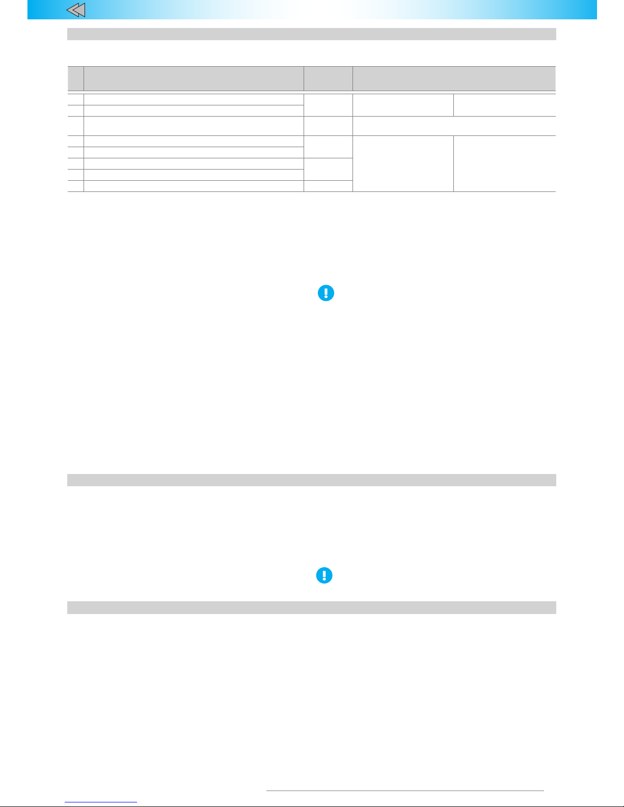
Menu 2. User settings
No. Ty p e
Factory
default
settings
Number of audible signals
1 Immobilizer
On 1 – ON 2 – OFF
2 AntiHiJack
3 AntiHiJack response delay 1
Range 1 to 10 1 – 100 m; ...10 – 1000 m. Sets the
distance until the engine lock
4 Audio conrmation of authentication by PIN-code
On
1 – ON 2 – OFF
5
Automatic deactivation of Maintenance mode
6
Activation of Central Lock while driving
Off
7 Deactivation of Central Lock after ignition is turned off
8 Automatic window roll up (Comfort feature) On
Programming sequence
1. Tur n the ignition on.
2. Enter PIN code, wait for confirmation.
3. Once the system has been powered, within 10 seconds enter
the configuration menu by pressing the Programming button
12 times. If your actions are correct, the Immobilizer will
confirm it by 4 audible signals.
4. Select the option from the menu by pressing the Programming
button a required number of times (equal to the number of the
option). The Immobilizer will acknowledge the option number
by a series of audible signals.
5. Go to option setting by pressing and holding the brake pedal.
The Immobilizer will notify of the option status by a series of
audible signals of a changing duration.
6. Adjust option settings by pressing the Programming button
the number of times matching the number of steps from the
current status to the required one. Please remember that from
the last function the program will go to the first one.
7. Release the brake pedal. Now you can move to programming
the next function or exit the programming mode.
8. Go to configuring another option by pressing the Programming
button the number of times matching the number of steps
from the current option to the required one. For example, to
go from option 2 (AntiHiJack) to option 6 (Activation of Central
Lock while driving) press the Programming button 4 times.
You can exit programming mode at any moment by turning off
the ignition. A trill will sound. If no actions were taken within
60 seconds and brake pedal was released, the Immobilizer will
exit programming mode.
You can exit programming mode at any moment by turning off the
ignition. A trill will sound. If no actions were taken within 60 seconds
and brake pedal was released, the Immobilizer will exit programming
mode.
• If the vehicle has travelled 10 km after installation, and
factory default PIN code remained unchanged, it is
allowed to use PIN code “2” for identity verification by
pressing an integrated button.
• To change method of authentication (option 9) you must
enter PUK-code: you can find it under the opaque cover
on the plastic card. No audible signals are generated
before entering the PUK-code. Afterwards a trill will
sound, and the system will indicate the option number.
• PUK-code as a means for changing the authentication
method is not required if:
1. the vehicle travelled less than 10 km after installation
of the Immobilizer (Speed Control is available).
2. the ignition was not active for more than 20 minutes
after installation of the Immobilizer (Speed Control
is not available)
Changing PIN code
1. Tur n the ignition on.
2. Enter PIN code, wait for confirmation.
3. Press the Programming button 10 times within 14 seconds
after the authentication. Wait for confirmation by 1 audible
signal.
4. Set the new PIN code by using any combination of buttons.
Now you can use the buttons. Pressing is confirmed by an
audible signal.
5. Wait for confirmation by 1 audible signal.
6. Re-enter the new PIN code.
7. Wait for confirmation:
• 2 audible signals and a sound trill mean that the PIN code
has been changed and the Immobilizer has left the PIN
code changing mode.
• Sound alert means that the PIN code has not been changed:
An error occurred while entering a new PIN. Repeat PIN
changing procedure starting from step 4.
You can exit the PIN code changing mode anytime by turning the
ignition off.
• You cannot change PIN to «1» – a single push of a button.
Reassigning Programming Button
1. Reset all settings to factory default.
2. Run the Immobilizer interfacing procedure.
3. If analog steering wheel buttons are used please define them
(see above for the description of this procedure).
4. In order to assign any of the buttons recognized by the
Immobilizer as the Programming button, press the selected
button and hold it for at least 5 seconds until a long audible
signal is heard.
The Programming button can be assigned within 15 minutes after
the Immobilizer interfacing with the vehicle.
Page 10

10
TEC- 61201-1 Technical Manualе PRIZRAK-510, 520 v7
Examples of programming
Example 1
Objective: Change the factory settings of the Immobilizer. Set
Output 2 – Engine locking – to normally open relay control.
Execution:
1. Tur n the ignition on.
2. Enter PIN code, wait for confirmation.
3. Once the system has been powered, within 10 seconds enter
Menu 1 by pressing Programming button 10 times. If your
actions are correct, the Immobilizer will confirm it by 3 audible
signals.
4. Select Option 3 – Engine locking – from Menu 1 by pressing
Programming but ton 3 times. The Immobilizer will acknowledge
the selection by a sequence of 3 audible signals.
5. Enter Option 3 menu by pressing and holding the brake pedal.
The Immobilizer will indicate the setting by 2 repeated audible
signals since the current (factory) setting is normally closed
relay control.
6. Select «normally open relay control». by pressing Programming
button 4 times. The Immobilizer will notify the selection of this
option by a single audible signal.
7. Exit the programming mode by turning the ignition off.
Example 2
Objective: Change the factory settings of the Immobilizer. Extend
the Anti HiJack activation distance from 100 to 300 meters.
Execution:
1. Tur n the ignition on.
2. Enter PIN code, wait for confirmation.
3. Once the system has been powered, within 10 seconds enter
Menu 2 by pressing Programming button 12 times. If your
actions are correct, the Immobilizer will confirm it by 4 audible
signals.
4. Select Option 3 – AntiHiJack response delay – from Menu 2 by
pressing Programming button 3 times. Immobilizer will confirm
the selection by emitting a sequence of 3 audible signals.
5. Enter Option 3 menu by pressing and holding the brake pedal.
The Immobilizer will inform you on the option setting by
repeated single audible signals because the current (factory)
setting is 1 (which stands for 100 meters distance).
6. Adjust the setting of option 3 by pressing the Programming
button 2 times, i.e. increase the option value by 2 increments
(1 + 2 = 3). Immobilizer will acknowledge the selection by
emitting a sequence of 3 audible signals (i.e. 300 m).
7. Exit the programming mode by turning the ignition off.
Resetting to factory default settings
There is a procedure of resetting the programmable settings, where all vehicle model settings are removed from Immobilizer’s permanent
memory while PIN code and all other programming options are returned to factory settings.
For vehicles with Immobilizer:
1. De-energize the Immobilizer.
2. Press and hold the integrated button (s e e «Immobilizer wiring
diagram»).
3. While holding the button, energize the Immobilizer. The
Immobilizer will start emitting an intermittent audible sound.
4. Release the button and wait for the audible signal to stop.
5. Tur n on the ignition. Enter PIN-code, a trill will be made.
6. Wait for an intermittent signal meaning the system was reset
to factory default settings. Switch the power off.
For vehicles without Immobilizer:
Reset ting can be done in three ways:
1. using an integrated button if the default PIN «2» has not been
changed and the vehicle has not travelled more than 10 km
after installation.
2. using the button and PUK.
3. By installing the Alarm in the same vehicle as it was installed
4. before (if you know the PIN-c o de).
Procedure for first two options:
1. Press and hold the integrated button (se e «Immobilizer wiring
diagram»).
2. While holding the button, energize the Immobilizer. The
Immobilizer will start emitting an intermittent audible sound.
3. Release the button and wait for the audible signal to stop.
4. If the vehicle has travelled less than 10 km after installation,
and factory default PIN remained unchanged, it is allowed to
use PIN code “2” by pressing an integrated button. Otherwise
enter PUK. A trill will sound.
5. Wait for an intermittent signal meaning the system was reset
to factory default settings. Switch the power off.
The protective layer can be removed and PUK can be entered
only by the registered user.
Page 11
11
TEC- 61201-1 Technical Manualе PRIZRAK-510, 520 v7
Immobilizer wiring diagram
X1
*
Connect to vehicle circuit
non-switching
voltage +12V
*
15 А – for two locks
or
programming and enable if the
vehicle CAN bus lacks
information about hood status
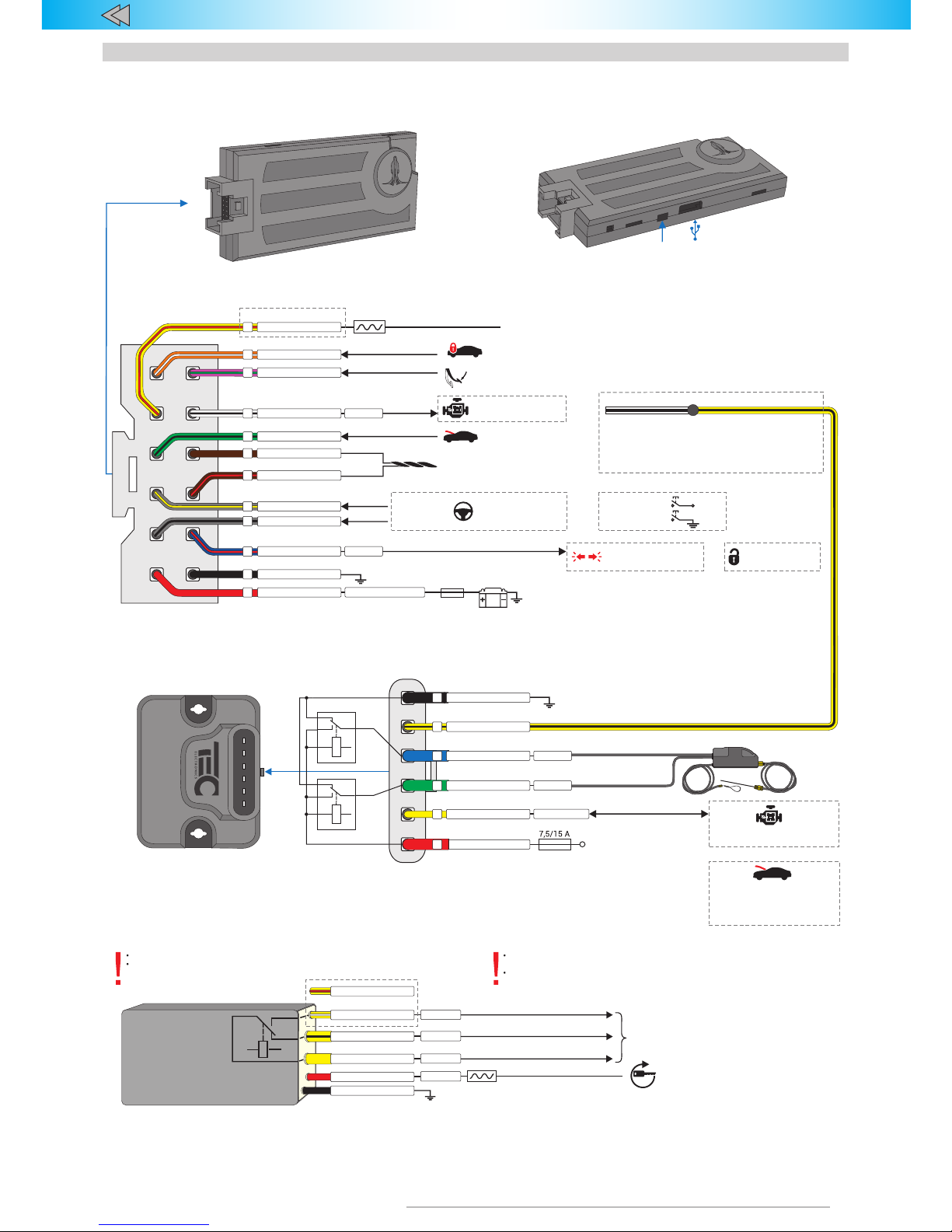
Hood status check Runа
Engine Lock
(factory setting)
Micro-USBLED
10 А
10 А
150 mA/1,5 mA
Program. output (-)/input (-)
PRIZRAK 500 v7
Схема подключения иммобилайзеров Призрак 500-й серии v7
Wireless pLine-221 relay (for PRIZRAK 520/540)
TP-BUS – digital bus for serial communication and connection
of additional devices by TEC Electronics
hood lock (+)
Open
Output
Close
Outputhood lock (+)
*
Maximum current through normally open relay is limited by the cross-section (0,35 мм2) of the wire Current consumption: 1 A (pulse) when transferred, up to 20 mA for acceptance
**
yellow and yellow/black wire
for locking (acts as a circuit breaker)
yellow and yellow/white (yellow/red) wire can be
used for sensor interlock (bypassing).
Interlocking output
•
•
On
Ignition 1
COM
10 А
Normally closed
10 А
*
Normally open
3 А
*
*
Data link and power supply
1 А/20 mA
No more than one relay is allowed
pLine-221 is a normally closed relay
Algorithm changes are not allowed
Engine Lock is enabled right after the vehicle starts moving. PRIZRAK receives
the information about the vehicle moving via CAN bus
If the central unit was removed, the relay will lock the engine using
accelerometer (once the vehicle starts moving)
yellow
/white
yellow
/white
or
red
black
yellow
yellow
/black
HCU-230 Hood module
6
black
5
4
blue
3
green
2
yellow
red
HCU-230 Hood locking
Brake light status check
Hood module control
Set option Engine locking to value 5 (see Hardware settings
configuration). To activate Engine Lock use Output 2
HCU-230 (yellow).
X1 Port (12-pin)
CAN-H
BRAKE
Program. input (+)
Program. input (+)
1
pink/green
or
Выход (-)
150 мА
Engine locking
2
white/black
CAN-L
CAN
Connected to CAN bus
(see Integrator files)
3
brown
7
orange/white
8
yellow/red
brown/red
4
for PRIZRAK 520/540
Link to pLine relay
Connect to vehicle circuit
with switching / non-switching voltage +12V
9
green/black
Програм. вход (-)
Check
hood status
Ground
6
black
12
red
12V
* **
200(1200) /5 mA
Output (+/-) with variable polarity
±150 mA
5
blue/red
3А
Alternate hazard
lights control
Subject to vehicle
Connect to steering
wheel buttons ONLY
in EXCLUSIVE CASES!
or
or
Analog button
Ref. ground
Output (-)
Input (+)
Positive button +12V
10
grey/
yellow
11
grey/black
Analog buttons Digital buttons
*
Standard current consumption in operating mode
for PRIZRAK 510/530 (PRIZRAK 520/540)
Standard current consumption in idle mode
**
yellow
/black
Negative button
1
Identity verification
impulse
Page 12

12
TEC- 61201-1 Technical Manualе PRIZRAK-510, 520 v7
Use the picture to draw arrangement
of alarm units. This can help when
trying to find specific units.
Схема расположения элементов иммобилайзера в автомобиле
Keep this sketch out of the reach of third parties.
Immobilizer units arrangement in the vehicle
Page 13
13
TEC- 61201-1 Technical Manualе PRIZRAK-510, 520 v7
Комплектнось
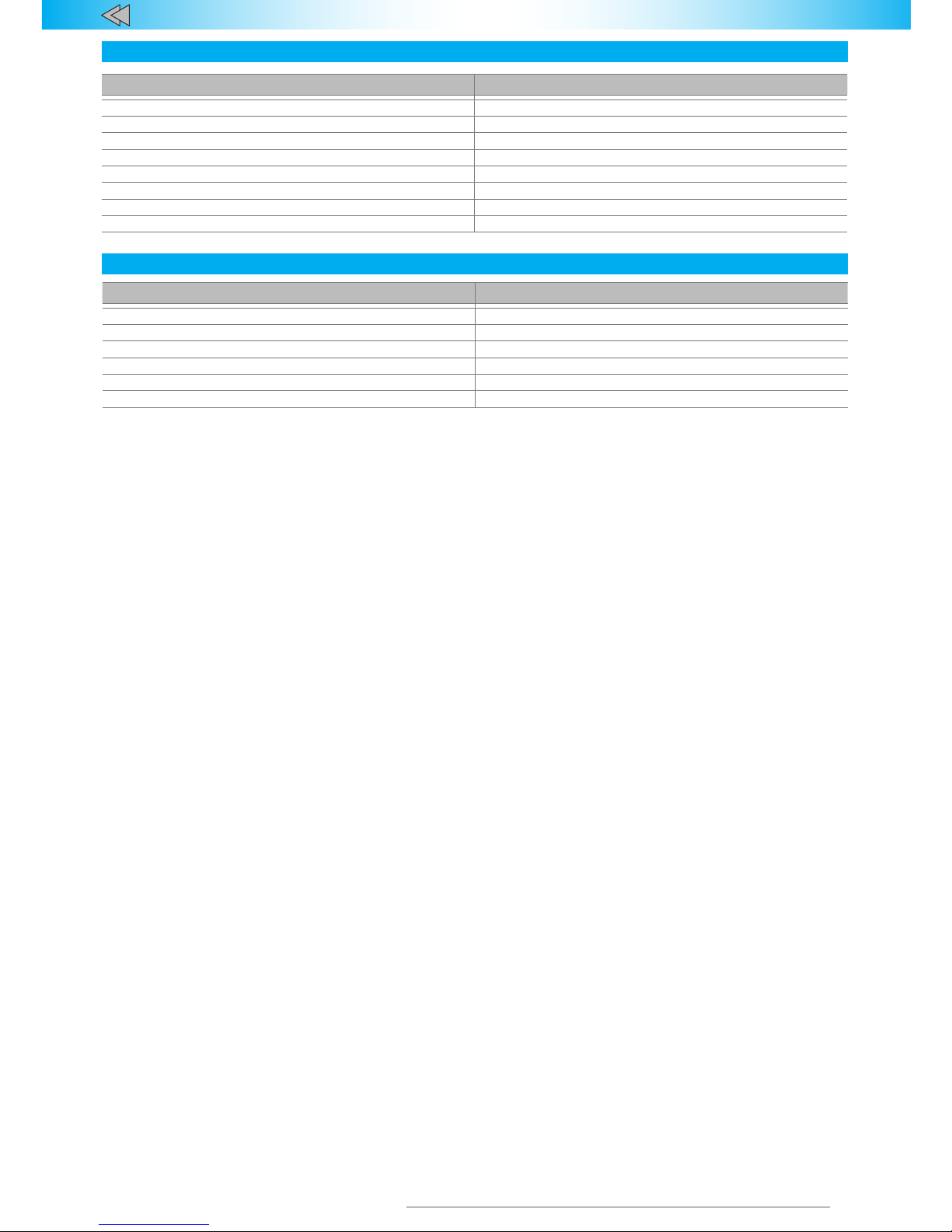
Designation Quantity, pcs.
Central unit 1
A set of wiring harness 1
pLine-221 relay (only for PRIZRAK-520) 1
Reminder card 1
User manual 1
Warranty certicate 1
Connection diagram 1
Packing 1
Технические данные и условия эксплуата
ции
Parameter Value
Power supply voltage, V 9 … 15
Maximum current consumption in standby mode, mA 5
Maximum current consumption in standby mode, mA 1200 (for PRIZRAK-520)/200 (for PRIZRAK-510)
Operating temperature, °С –40 … +85
Storage temperature, °С –40 … +85
Maximum relative air humidity, % 95
Standard scope of delivery
Specications and operating conditions
Page 14

14
TEC- 61201-1 Technical Manualе PRIZRAK-510, 520 v7
Page 15

15
TEC- 61201-1 Technical Manualе PRIZRAK-510, 520 v7
Page 16

www.tecel.ru/en
TECHNICAL MANUAL
Producer - TEC electronics Ltd.
The product is produced according to TU 4573-009-78025716-12.
Certificate of conformityTS RU C-RU.OC13.B.01026.
The product conforms to the requirements of the Technical reglament
of Custom Union TR TS 018/2011
"Safety of wheeled vehicles"
 Loading...