

Page 1

查询P0080SA供应商
SIDACtor Device
SIDACtor Device
Electrical Parameters
Part
Number *
P0080S_ 6 25 4 5 800 2.2 50 100
P0300S_ 25 40 4 5 800 2.2 50 110
P0640S_ 58 77 4 5 800 2.2 150 50
P0720S_ 65 88 4 5 800 2.2 150 50
P0900S_ 75 98 4 5 800 2.2 150 50
P1100S_ 90 130 4 5 800 2.2 150 40
P1300S_ 120 160 4 5 800 2.2 150 40
P1500S_ 140 180 4 5 800 2.2 150 40
P1800S_ 170 220 4 5 800 2.2 150 30
P2300S_ 190 260 4 5 800 2.2 150 30
P2600S_ 220 300 4 5 800 2.2 150 30
P3100S_ 275 350 4 5 800 2.2 150 30
P3500S_ 320 400 4 5 800 2.2 150 30
* For individual “SA”, “SB”, and “SC” surge ratings, see table below.
General Notes:
• All measurements are made at an ambient temperature of 25 °C. I
• I
is a repetitive surge rating and is guaranteed for the life of the product.
PP
• Listed SIDACtor devices are bi-directional. All electrical parameters and surge ratings apply to forward and reverse polarities.
• V
is measured at I
DRM
• VS is measured at 100 V/µs.
• Special voltage (V
• Off-state capacitance is measured at 1 MHz with a 2 V bias and is a typical value for “SA” and “SB” product. “SC” capacitance is
approximately 2x the listed value. The off-state capacitance of the P0080SB is equal to the “SC” device.
DO-214AA SIDACtor solid state protection devices protect telecommunications equipment
such as modems, line cards, fax machines, and other CPE.
SIDACtor devices are used to enable equipment to meet various regulatory requirements
including GR 1089, ITU K.20, K.21 and K.45, IEC 60950, UL 60950, and TIA/EIA-IS-968
(formerly known as FCC Part 68).
V
DRM
Vol ts
and V
S
DRM.
V
S
Vol ts
) and holding current (IH) requirements are available upon request.
DRM
V
Vol ts
T
I
DRM
µAmps
applies to -40 °C through +85 °C temperature range.
PP
I
S
mAmps
I
T
Amps
I
H
mAmps
C
pF
O
Surge Ratings
Series
I
PP
2x10 µs
Amps
I
PP
8x20 µs
Amps
I
PP
10x160 µs
Amps
I
PP
10x560 µs
Amps
I
PP
10x1000 µs
Amps
I
TSM
60 Hz
Amps
di/dt
Amps/µs
A 150 150 90 50 45 20 500
B 250 250 150 100 80 30 500
C 500 400 200 150 100 50 500
http://www.teccor.com 2 - 4 © 2002 Teccor Electronics
+1 972-580-7777 SIDACtor
®
Data Book and Design Guide
Page 2
Thermal Considerations
V
V
Package Symbol Parameter Val ue Unit
DO-214AA T
T
S
R
qJA
+I
+I
Operating Junction Temperature Range -40 to +150 °C
J
Storage Temperature Range -65 to +150 °C
Thermal Resistance: Junction to Ambient 90 °C/W
SIDACtor Device
-V
-V
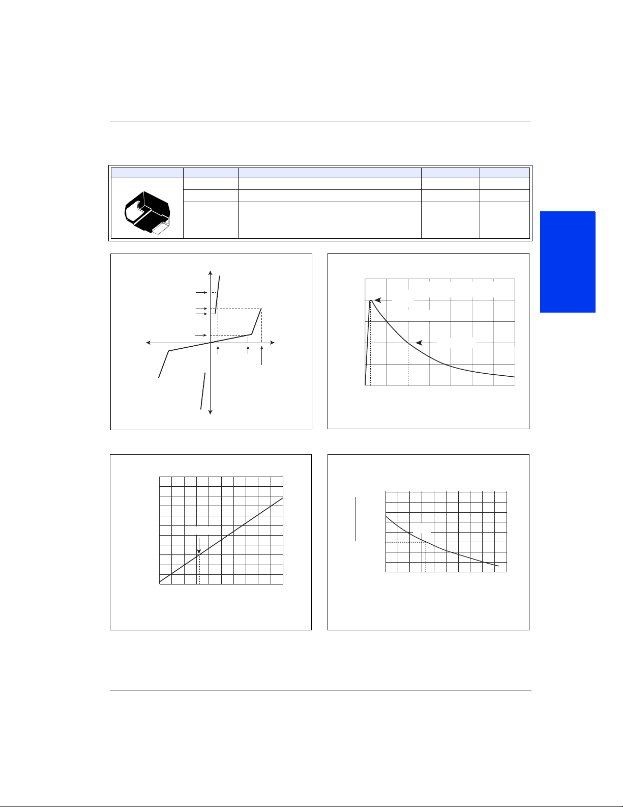
V-I Characteristics
14
12
10
8
6
Change – %
S
4
2
0
-4
Percent of V
-6
-8
-40 -20 0 20 40 60 80 100 120 140 160
I
I
T
T
I
I
S
S
I
I
H
H
I
I
DRM
DRM
V
V
V
-I
-I
DRM
V
T
DRM
T
V
V
25 °C
Junction Temperature (TJ) – °C
PP
100
Waveform = t
– Peak Pulse Current – %I
PP
I
50
0
t
r
0
+
+
S
S
tr = rise time to peak value
= decay time to half value
t
d
Peak
Val ue
x t
r
Half Value
t
d
t – Time (µs)
d
Data Sheets
tr x td Pulse Wave-form
2.0
1.8
1.6
H
= 25 °C)
I
1.4
C
1.2
(T
H
I
1.0
0.8
0.6
Ratio of
0.4
-40 -20 0 20 40 60 80 100 120 140 160
25 °C
Case Temperature (TC) – °C
Normalized VS Change versus Junction Temperature
© 2002 Teccor Electronics 2 - 5 http://www.teccor.com
SIDACtor
®
Data Book and Design Guide +1 972-580-7777
Normalized DC Holding Current versus Case Temperature
 Loading...