

TEC POS Terminal
ST-6400 SERIES
Owner’s Manual
CE Compliance (For EU only)
This product complies with the requirements of EMC and Low Voltage Directives including their
amendments.
WARNING
This is a Class A product. In a domestic environment this product may cause radio interference in which
case the user may be required to take adequate measures.
Warnung
Dies ist ein Klasse A Produkt. In einer örtlichen Umgebung kann dieses Gerät Funkstörungen verursachen.
ATTENTION
Ce produit est de classe A. Dans un environnement domestique, il peut causer des interférences radio.
Auquel cas, I’utilisateur sera amené à prendre les mesures adéquates.
Atención
Este es un producto de la clase A. En ambientes domésticos éste producto puede causar radio
interferencias en cuyo caso el usuario deberá tomar las medldas oportunas.
VERWITTIGING
Dit is een klasse A produkt. Het gebruik hiervan kan radio interferenties veroorzaken die de gebruiker
ertoe kunnen dwingen sommige maatregelen te moeten treffen.
Schallemission : unter 70 dB (A) nach DIN 45635 (ISO 7779).........Thermodrucker-Type
Schallemission : 71 dB (A) nach DIN 45635 (ISO 7779)..........Matrixdrucker-Type
FCC Notice
This equipment has been tested and found to comply with the limits for a Class A digital device, pursuant
to Part 15 of the FCC Rules. These limits are designed to provide reasonable protection against harmful
interference when the equipment is operated in a commercial environment. This equipment generates,
uses, and can radiate radio frequency energy and, if not installed and used in accordance with the instruction
manual, may cause harmful interference to radio communications. Operation of this equipment in a
residential area is likely to cause harmful interference in which case the user will be required to correct
the interference at his own expense.
Changes or modifications not expressly approved by manufacturer for compliance could void the user’s
authority to operate the equipment.
CAUTION
The connectors, DRW1/2, are exclusive for TOSHIBA TEC Drawer Unit.
Do not connect the equipment which is not specified by the manufacturer's instructions.
Copyright © 2001
by TOSHIBA TEC CORPORATION
All Rights Reserved
570 Ohito, Ohito-cho, Tagata-gun, Shizuoka-ken, JAPAN
Safety Summary
Safety Summary
Personal safety in handling or maintaining the equipment is extremely important. Warnings and Cautions
necessary for safe handling are included in this manual. All warnings and cautions contained in this
manual should be read and understood before handling or maintaining the equipment.
Do not attempt to effect repairs or modifications to this equipment. If a fault occurs that cannot be rectified
using the procedures described in this manual, turn off the power, unplug the machine, then contact your
authorized TOSHIBA TEC representative for assistance.
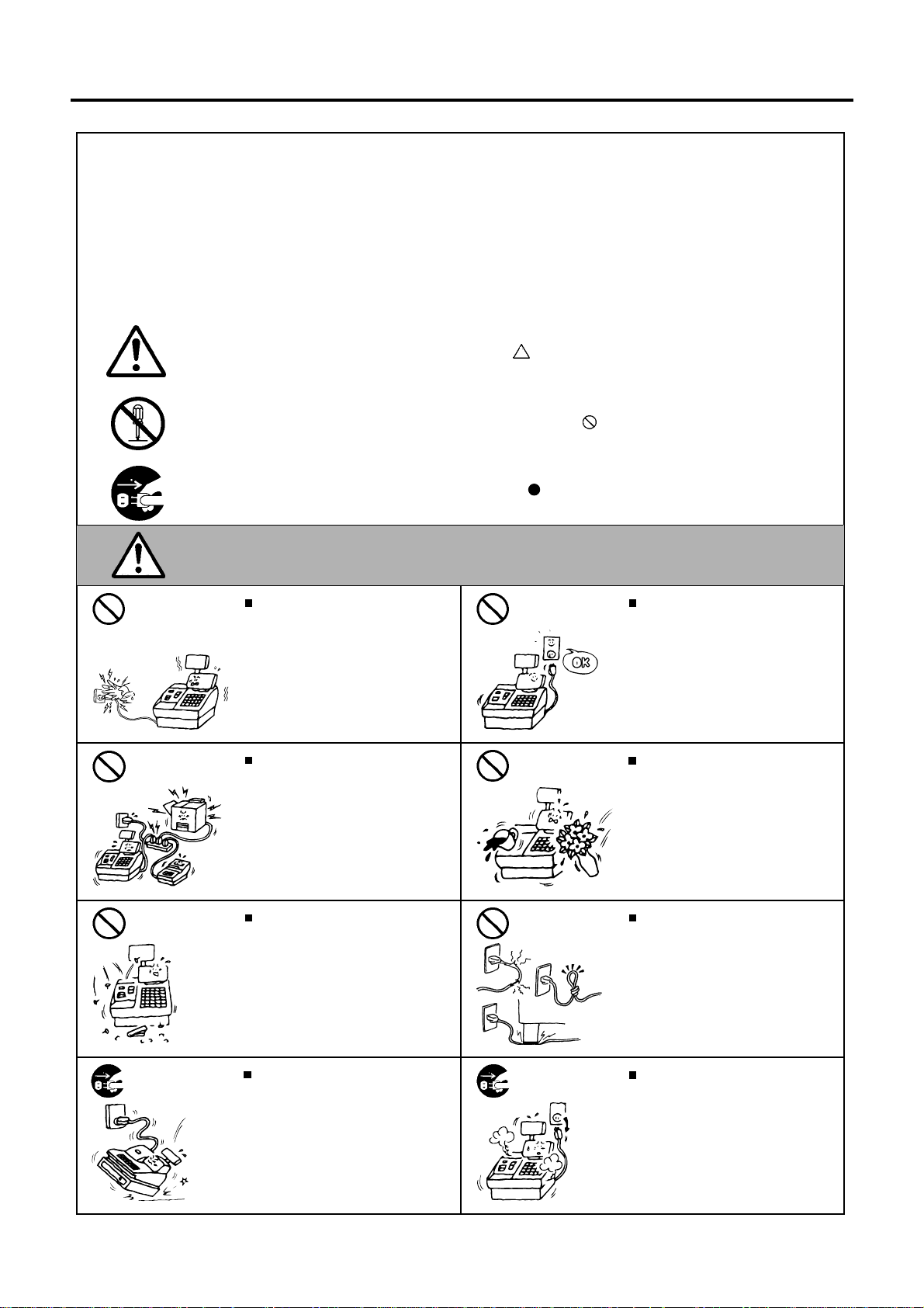
Meanings of Each Symbol
This symbol indicates warning items (including cautions).
Specific warning contents are drawn inside the symbol.
(The symbol on the left indicates a general caution.)
This symbol indicates prohibited actions (prohibited items).
Specific prohibited contents are drawn inside or near the symbol.
(The symbol on the left indicates “no disassembling”.)
This symbol indicates actions which must be performed.
Specific instructions are drawn inside or near the symbol.
(The symbol on the left indicates “disconnect the power cord plug from the outlet”.)
EO1-11099
This indicates that there is the risk of death or serious injury if the
WARNING
Prohibited
Prohibited
Prohibited Prohibited
Do not plug in or unplug the power
cord plug with wet hands as this may
cause electric shock.
If the machines share the same
outlet with any other electrical
appliances which consume large
amounts of power, the voltage will
fluctuate widely each time these
appliances operate. Be sure to
provide an exclusive outlet for the
machine as this may cause fire or
electric shock.
Do not insert or drop metal,
flammable or other foreign objects into
the machines through the ventilation
slits, as this may cause fire or electric
shock.
machines are improperly handled contrary to this indication.
Any other than the
specified AC voltage
is prohibited.
Prohibited
Do not use voltages other than the
voltage (AC) specified on the rating
plate, as this may cause fire or
electric shock.
Do not place metal objects or
water-filled containers such as flower
vases, flower pots or mugs, etc. on
top of the machines. If metal objects
or spilled liquid enter the machines,
this may cause fire or electric
shock.
Do not scratch, damage or modify
the power cords. Also, do not place
heavy objects on, pull on, or excessively bend the cords, as this may
cause fire or electric shock.
Disconnect
the plug.
If the machines are dropped or their
cabinets damaged, first turn off the
power switches and disconnect the
power cord plugs from the outlet, and
then contact your authorized
TOSHIBA TEC representative for
assistance. Continued use of the
machine in that condition may cause
fire or electric shock.
(i)
Disconnect
the plug.
Continued use of the machines in an
abnormal condition such as when the
machines are producing smoke or
strange smells may cause fire or elec-
tric shock. In these cases, immediately turn off the power switches and
disconnect the power cord plugs from
the outlet. Then, contact your authorized TOSHIBA TEC representative for
assistance.
Safety Summary
EO1-11099
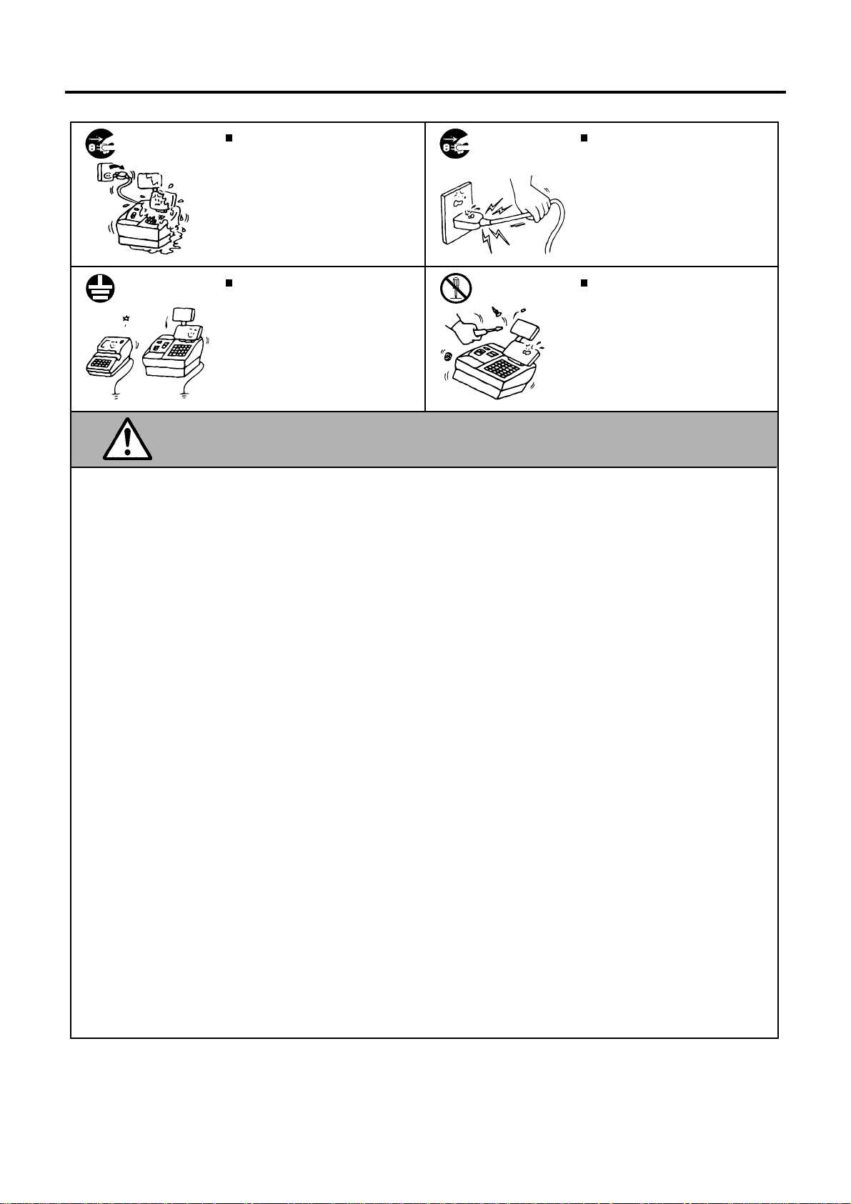
Disconnect
the plug.
Connect a
grounding
wire.
If foreign objects (metal fragments,
water, liquids) enter the machines,
first turn off the power switches and
disconnect the power cord plugs from
the outlet, and then contact your
authorized TOSHIBA TEC representative for assistance. Continued
use of the machine in that condition
may cause fire or electric shock.
Ensure that the equipment is
properly grounded. Extension cables
should also be grounded. Fire or
electric shock can occur on improperly grounded equipment.
Disconnect
the plug.
No
disassembling.
When unplugging the power
cords, be sure to hold and pull on
the plug portion. Pulling on the cord
portion may cut or expose the internal wires and cause fire or electric
shock.
Do not remove covers, repair or
modify the machine by yourself. You
may be injured by high voltage, very
hot parts or sharp edges inside the
machine.
Unauthorized modification is prohibited.
This indicates that there is the risk of personal Injury or damage to
CAUTION
objects if the machines are improperly handled contrary to this indication.
Precaution
The following precautions will help to ensure that this machine will continue to function correctly.
• Try to avoid locations that have the following adverse conditions:
* Temperatures out of the specification * Direct sunlight * High humidity
* Shared power socket * Excessive vibration * Dust/Gas
• Do not subject the machine to sudden shocks.
• Do not press the keys too hard. Keys will operate correctly if they are touched lightly.
• Clean the cover and keyboard, etc. by wiping with a dry cloth or a cloth soaked with detergent and wrung out
thoroughly. Never use thinner or other volatile solvent for cleaning.
• At the end of the day, turn the power OFF, then clean and inspect the exterior of the machine.
• Try to avoid using this equipment on the same power supply as high voltage equipment or equipment likely to
cause mains interference.
• USE ONLY TOSHIBA TEC SPECIFIED consumables.
• DO NOT STORE the consumables where they might be exposed to direct sunlight, high temperatures, high
humidity, dust, or gas.
• When moving the machine, take hold of the drawer and lift the machine.
• Do not place heavy objects on top of the machines, as these items may become unbalanced and fall causing
injury.
• Do not block the ventilation slits of the machines, as this will cause heat to build up inside the machines and
may cause fire.
• Do not lean against the machine. It may fall on you and could cause injury.
Request Regarding Maintenance
• Utilize our maintenance services.
After purchasing the machines, contact your authorized TOSHIBA TEC representative for assistance once per year or
so to have the inside of the machines cleaned. Otherwise, dust will build up inside the machines and may cause fire or
malfunction. Cleaning is particularly effective before humid rainy seasons.
• Our maintenance service performs the periodic checks and other work required to maintain the quality and
performance of the machines, preventing accidents beforehand.
For details, please consult your authorized TOSHIBA TEC representative for assistance.
• Using insecticides and other chemicals
Do not expose the machines to insecticides or other volatile solvents, as this will deteriorate the cabinet or other parts
or cause the paint to peel.
(ii)

EO1-12027
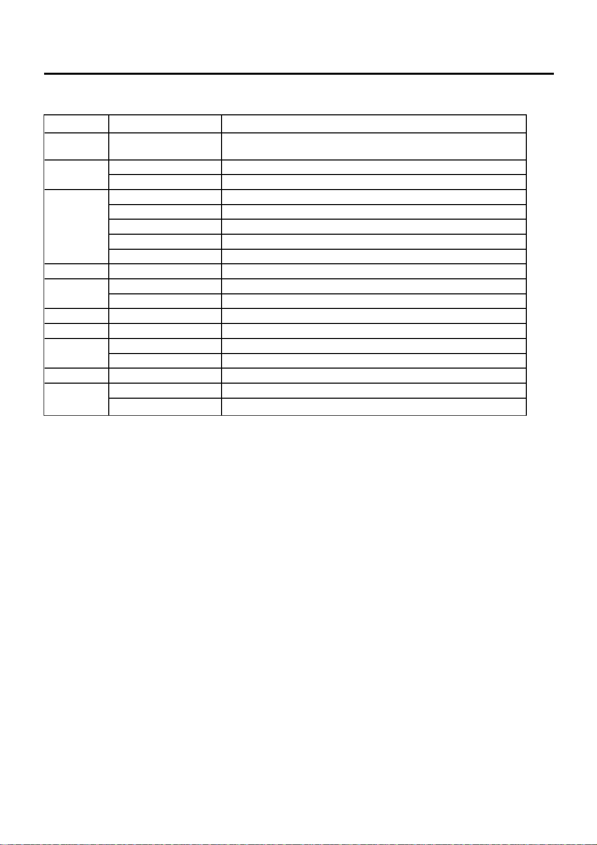
TABLE OF CONTENTS
Page
1. INTRODUCTION ......................................................................................................................... 1-1
1.1 Applicable Model ................................................................................................................ 1-1
1.2 Accessor ies ........................................................................................................................ 1-2
2. SPECIFICATIONS ....................................................................................................................... 2-1
2.1 Basic Specifications............................................................................................................ 2-1
2.2 Option ................................................................................................................................. 2-2
2.3 Receipt/Journal Paper Roll for the Dot Printer.................................................................... 2-3
2.4 Thermal Paper Roll for the Thermal Printer ........................................................................ 2-4
3. OVERVIEW.................................................................................................................................. 3-1
3.1 Front/Rear View .................................................................................................................. 3-1
3.2 Control Lock and Mode Selector Keys................................................................................ 3-3
3.3 Operation Panel.................................................................................................................. 3-3
4. FLOPPY DISK AND FLOPPY DISK DRIVE (with FDD Model) ................................................. 4-1
4.1 Floppy Disk Write Protection .............................................................................................. 4-1
4.2 Handling the Floppy Disk Drive .......................................................................................... 4-1
5. HANDLING OF THE PRINTER (2-station Dot Printer Type) ..................................................... 5-1
5-1 Removing the Receipt Cover.............................................................................................. 5-1
5.2 Removing the Ribbon Cover............................................................................................... 5-2
5.3 Installing/Replacing the Receipt Roll .................................................................................. 5-3
5.4 Installing/Replacing the Journal Roll .................................................................................. 5-5
5.5 Setting/Replacing the Ribbon Cassette .............................................................................. 5-7
5.6 Replacing the Store Name/Message Stamp with Ink ......................................................... 5-8
6. HANDLING OF THE PRINTER (Single Station Thermal Printer Type)..................................... 6-1
6.1 When using the Auto Loading Function.............................................................................. 6-1
6.2 When using the Manual Loading Function ......................................................................... 6-3
7. DISPLAY (LIUST-51) ................................................................................................................... 7-1
8. DRAWER..................................................................................................................................... 8-1
8.1 Manual Drawer Release and Lock...................................................................................... 8-1
8.2 Removing the Drawer ......................................................................................................... 8-2
8.3 Locking the Cash Drawer Cover (CDC).............................................................................. 8-2
8.4 Changing the Layout of the Money Case............................................................................ 8-2
8.5 Media Slot........................................................................................................................... 8-4
9. GENERAL MAINTENANCE........................................................................................................ 9-1
9.1 Cleaning ............................................................................................................................. 9-1
10. TROUBLESHOOTING .............................................................................................................. 10-1
1. INTRODUCTION
1.1 Applicable Model
EO1-12027
1. INTRODUCTION
Thank you for purchasing the TOSHIBA TEC ST-6400 Series POS Terminal.
This POS Terminal contains all the high performance register functions necessary for a specialty store POS terminal
and enables the user oriented system configuration. By adopting a high-speed CPU (CeleronTM 566MHz), memory with
large capacity, and magnetic device, this POS Terminal flexibly accepts the modification corresponding to the future
system environment as the user expects.
This manual describes the functions and handling of this POS terminal and should be read carefully to help gain
maximum performance and life from your POS terminal.
For most queries please refer to this manual and keep it safe for future reference.
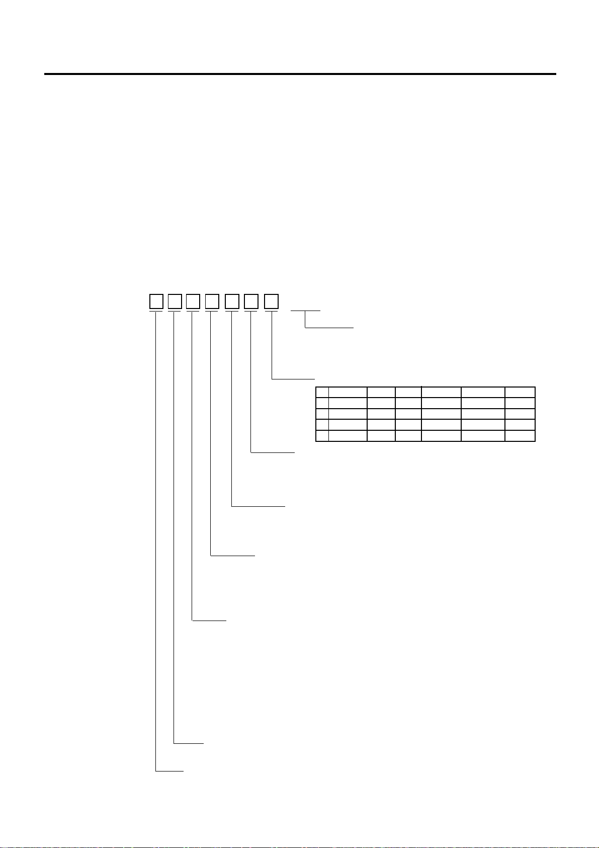
1.1 Applicable Model
Model Name Description
ST-6401- -QM
Printer Type
1: 2-station dot printer (58 mm)
S: Single station thermal printer (80 mm)
4: 2-station dot printer (58 mm)
7: 2-station dot printer (58 mm)
A: 2-station dot printer (45 mm)
CPU Frequency
5: 566 MHz
CPU Type
C: Celeron
TM
Destination Code (Country/Region)
QM: Standard for worldwide
Internal Construction
Memory HDD FDD SIO1,2 NVRAM USB
1 64MB No No No No Yes
5 64MB No No Yes No Yes
A 64MB No Yes No 128KB Yes
B 64MB No Yes No No Yes
Packing (Drawer)
N: None
4: With ESP Drawer (MC-4 type)
8: With ESP Drawer (MC-8 type)
Packing (Display)
N: None
P: With Pole
R: With Remote Indicator Unit + Pole
Keyboard Type
0: Normal keyboard (1x1 keys only)
1: Flat keyboard
2: Combination keyboard
3: Normal Keyboard (12 double keys)
Single validation/full cut
Multi validation/full cut
Multi validation/full & stub cut
Multi validation/full & stub cut
1-1
1. INTRODUCTION
EO1-12027
1.2 Accessories
1.2 Accessories
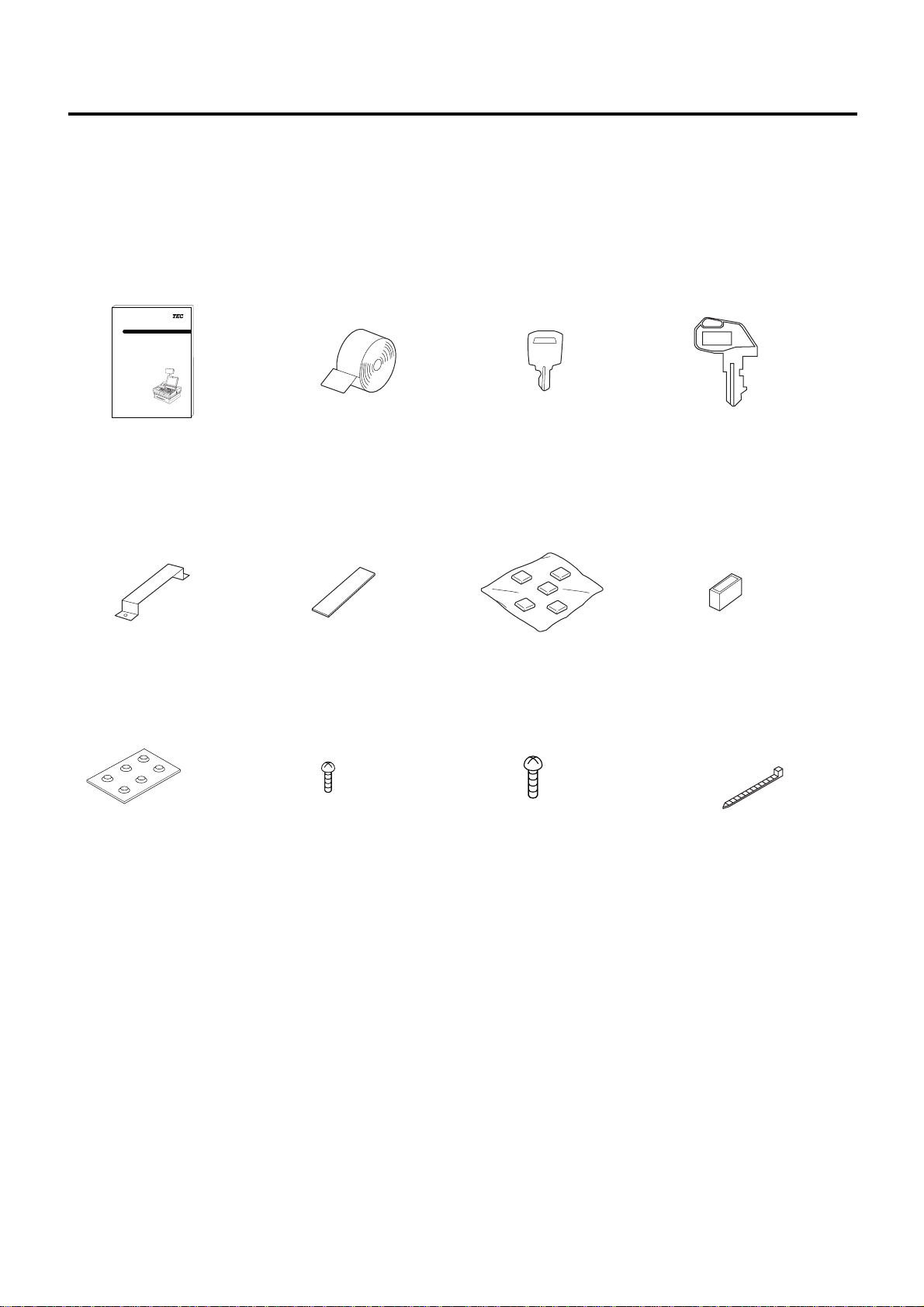
Confirm that all the following Accessories are contained in the carton. If any accessories are missing or damaged,
contact your nearest TOSHIBA TEC service representative.
• Accessories common to the all models
TEC POS Terminal
ST-6400 SERIES
Owner's Manual
TEC
TOSHIBA TEC CORPORATION
TEC
Owner’s Manual (1 pc.)
MCR Stay (1 pc.)
Rubber Foot (6 pcs.)
Paper Roll
2 pcs. : Dot Printer
(
1 pc. : Thermal Printer
Top Dummy Cover (4 pcs.)
Bind Screw M3x6
(4 pcs.)
(Used to secure the FDD)
FDD Cover Key
(1 set: 2 keys)
)
Key Cap Set
(1x1: 66 caps/Keyboard type :0)
(1x1:42 caps,1x2:12 caps/Key-
board type :3)
Bind Unify Screw No.6x4.5
(8 pcs.)
(Used to secure the HDDs)
Mode Selector Key Set (1 set)
REG, X, MA, S keys;
2 keys respectively
Short Plug (1 pc.)
Fasten Band (1 pc.)
(Used to secure the
Display Cable)
1-2
1. INTRODUCTION
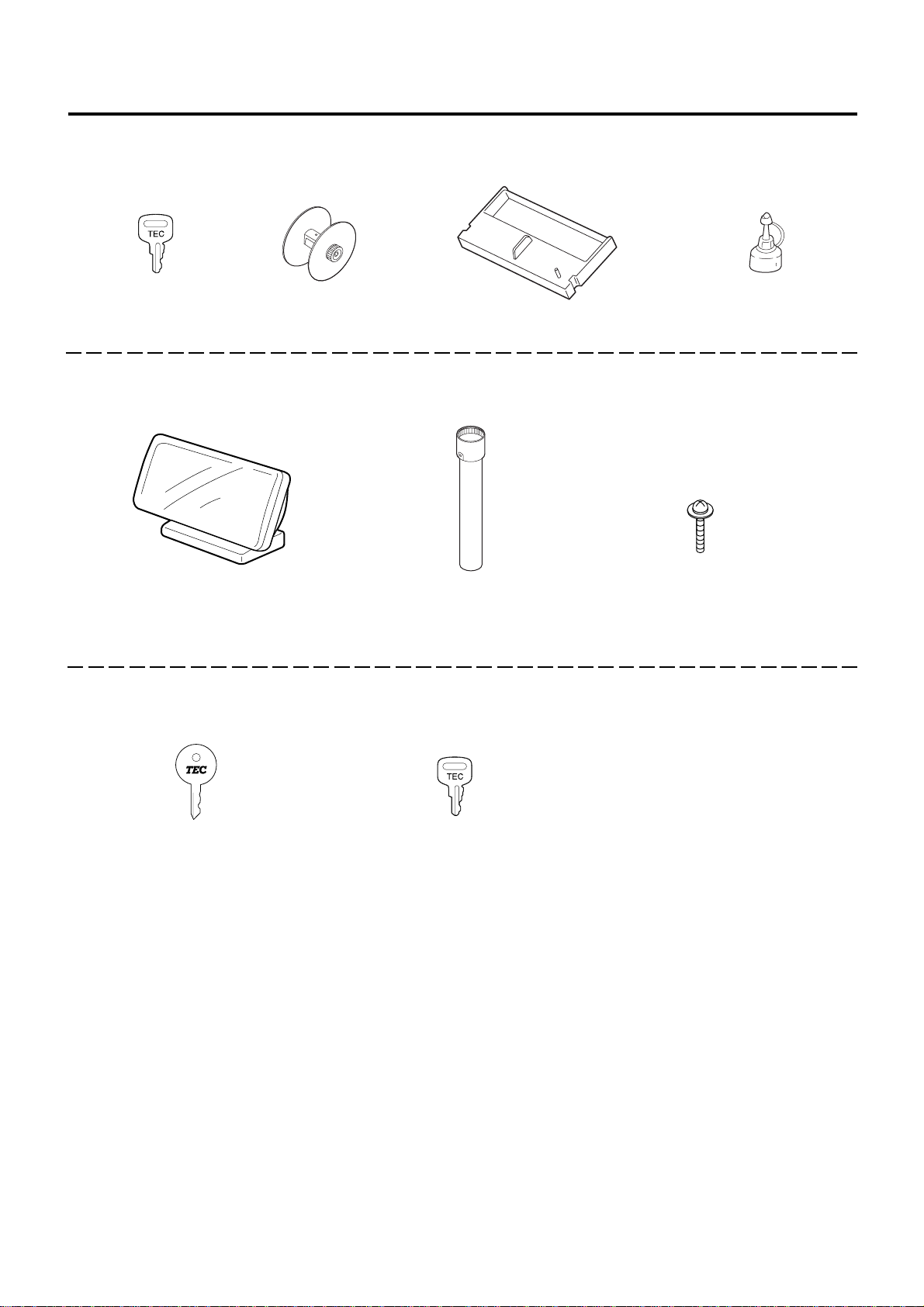
• Only for the model including the Dot Printer
EO1-12027
1.2 Accessories
Receipt Cover Key
Take-up Reel (1 pc.)
Ribbon Cassette (1 pc.)
(1 set: 2 keys)
• Only for the model including the Display Unit as standard
Display Unit (1 pc.)
Pole Unit (1 pc.)
• Only for the model including the Drawer Unit as standard
Stamp Ink (1 pc.)
Double Sems Screw M3x45
(2 pcs.)
(Used to secure the Pole Unit
to the Drawer)
Drawer Release Key
(1 set: 2 keys)
Cash Drawer Cover Key
(1 set: 2 keys)
1-3
2. SPECIFICATIONS
2.1 Basic Specifications
EO1-12027
2. SPECIFICATIONS
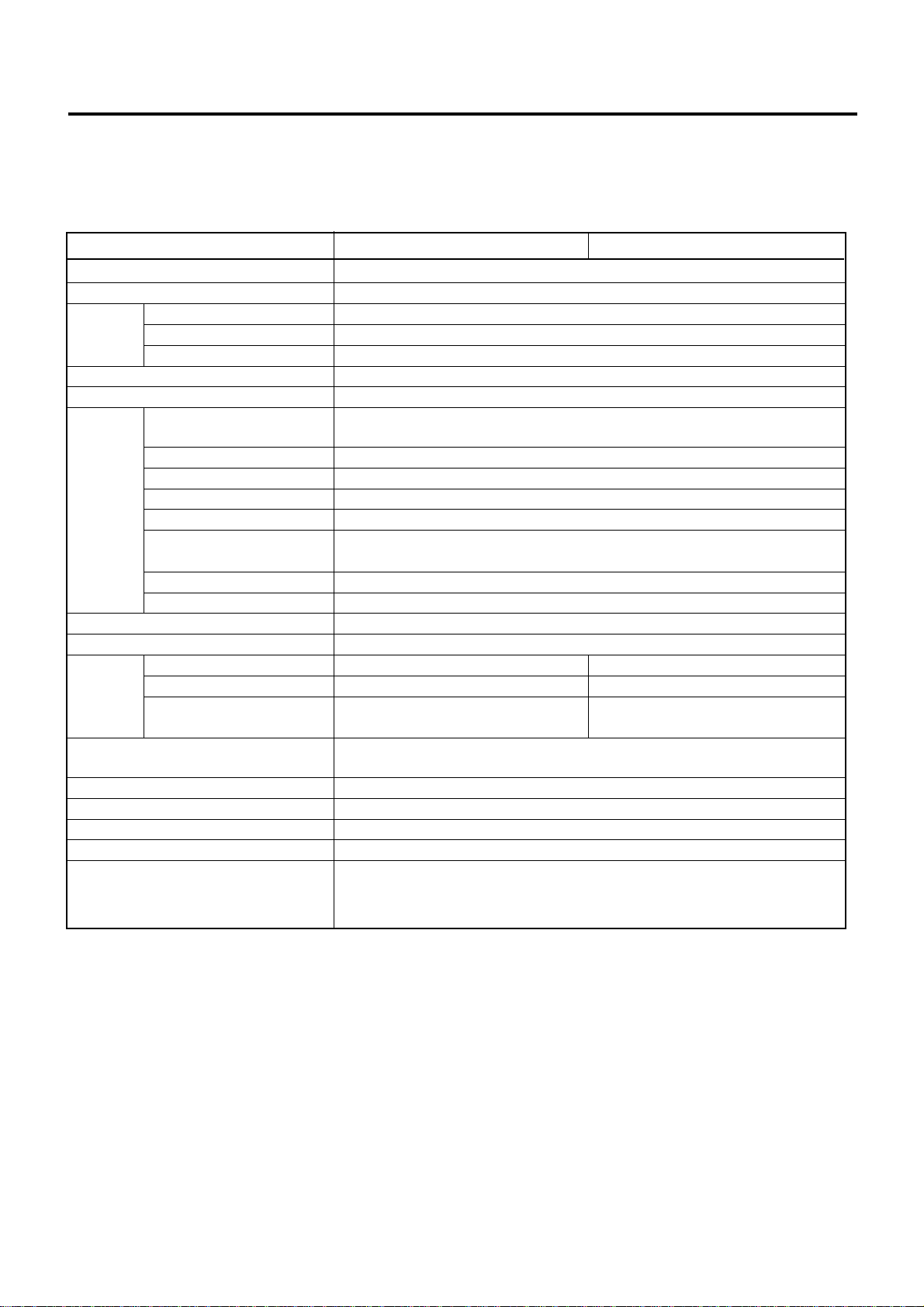
2.1 Basic Specifications
ST-6401-C51/4/7/AXXXX-QM ST-6401-C5SXXXX-QM
CPU Celeron™ 566MHz
BIOS ROM 512KB Flash ROM
Capacity 64MB as standard, expandable up to 512MB
RAM Type SDRAM, non parity bit, without ECC, PC100 or more
Socket 168-pin DIMM connector x 2 slots
Secondary Cache 128KB (CPU on die)
PCI Bus Up to two PCI standard boards can be installed
Interface Serial I/F
Parallel I/F LPT: D-sub 25-pin female connector
Keyboard I/F PS-2 interface: 1 channel
Mouse I/F PS-2 interface: 1 channel
Drawer I/F TEC standard 24V drawer: 2 channels
VGA I/F (Analogue RGB) VGA Controller: Intel® 82810E built-in (Directly AGP connection)
LAN I/F IEEE802.3 10BASE-T/100BASE-TX
USB I/F USB1 and USB2: 2 channels
Floppy Disk Drive One 3.5-inch FDD (1.44MB/720KB format)
Hard Disk Drive 3.5-inch, IDE I/F ( Dealer option)
Printer Printer Model DPR-245A or 258A series LT-380
Printing Method 2-station dot matrix Line Thermal Direct
Roll Paper Width 45mm (DPR-245A) 80mm
Input Voltage AC: 100 - 127V +5%/-10%, 50/60 Hz
Power Consumed 180W
Ambient Temperature 5°C to 35°C
Relative Humidity 20% to 80% (no condensation)
Weight 12Kg (excluding options)
Dimension Dot Printer Model : 493(W) x 469(D) x 199.5(H) mm without Drawer
(NOTE 3)
COM1, COM2 : D-sub 9-pin male connector
COM3, COM4, SIO1, SIO2 : D-sub 9-pin female connector
Video Memory: The system memory used
58mm (DPR-258A)
220 - 240V +10%/-10%, 50/60 Hz
Dot Printer Model : 493(W) x 469(D) x 305 (H) mm with Drawer
Thermal Printer Model : 493(W) x 469(D) x 192.5(H) mm without Drawer
(NOTE 2)
(NOTE 4)
NOTES: 1 ) Celeron™ is a registered trade mark of Intel Corporation.
2) Board size (Lower Slot): 140mm (One board)
Board size (Upper Slot): 185mm (One board)
3) Some models are provided with the SIO1 and SIO2 as standard.
4) Some models are provided with the 3.5" FDD as standard.
2-1
2. SPECIFICATIONS
2.2 Option
Option Name Type Description
Drawer Unit DRWST-64 Series 24V-drive ESP type drawer
Size and Weight: 460(W) x 400(D) x 115(H) mm 8.6Kg
Remote LIUST-51 Series 20 characters x 2 lines dot display
Display Unit LIUST-53 Series 256 x 64 dot display
Scanner HS-530-RS Series Touch scanner (RS-232C Interface Type)
Unit LS-770 Series Vertical laser slot scanner
LS-770-H Series Horizontal laser slot scanner
LS-780 Series Vertical laser slot scanner
LS-780-H Series Horizontal laser slot scanner
FDD FDDST-51 3.5-inch 1.44MB FDD Unit
NV-RAM NVMST-50-32 32KB NV-RAM
NVMST-50-128 128KB NV-RAM
Pole Option POLST-51 Pole type mounting kit for the LIUST-51/53
MCR MCRST-50 Magnetic Card Reader for Normal keyboard type
Display TFTST-52T 10.4-inch TFT Display with touch panel (without VGA board)
TFTST-56T 12.1-inch TFT Display with touch panel (with VGA board)
VGA Board VGAST-52-12 VGA board for the TFTST-52T
Plate KITST-65-1 VGA board attachment plate for the TFTST-52T
KITST-65-2 VGA board attachment plate for the TFTST-56T
EO1-12027
2.2 Option
2-2
2. SPECIFICATIONS
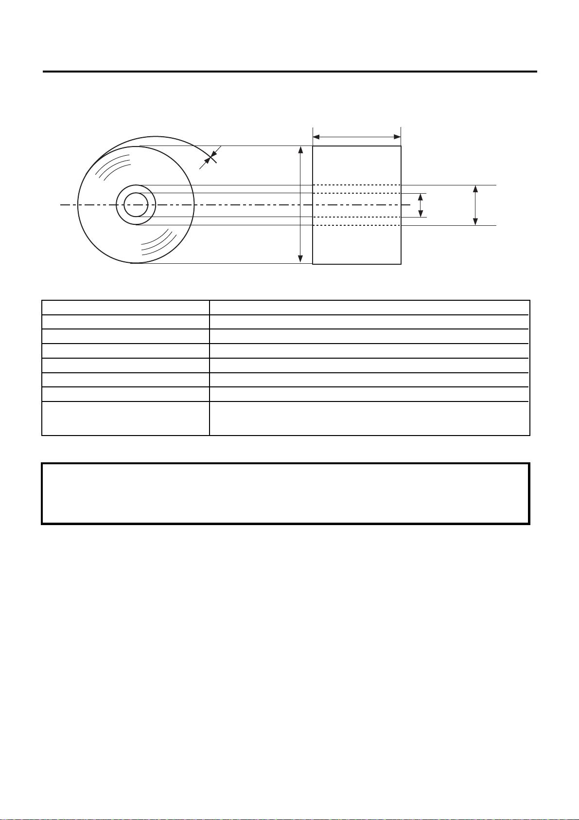
2.3 Receipt/Journal Paper Roll for the Dot Printer
Width (W)
Paper
thickness (T)
EO1-12027
2.3 Receipt/Journal Paper Roll for the Dot Printer
Inner core
diameter (ID)
Outer
diameter (D)
Outer core
diameter (OD)
Paper Type Paper rolled with the print side facing outside.
Width (W) 45 +0/-1 mm (DPR-245A Series) 58 +0/-1 mm (DPR-258A Series)
Outer diameter (D) 80 mm
Paper thickness (T) 0.083 ±0.005 mm
Weight 54.3±2g/m
2
Outer core diameter (OD) 25 mm
Inner core diameter (ID) 18 +0/-0.5 mm
Recommended paper 45R-80 (MHG01-00105/06) TOSHIBA TEC (DPR-245A Series)
58R-80 (MHG01-00109/10) TOSHIBA TEC (DPR-258A Series)
CAUTION!
Use only paper which meet specified requirements. Use of non-specified paper may shorten the head life of printer,
result in problems with print quality, or cause a paper feed failure.
All paper should be handled with care to avoid any damage to the paper. Read the following guideline carefully.
• Do not store the paper for longer than the manufacture’s recommended shelf life.
• Store the paper in a cool, dry place. Avoid areas where they would be exposed to direct sunlight, high temperature,
high humidity, dust or gas.
For further information please contact your authorised TOSHIBA TEC represrntative or authorised paper manufacturer.
2-3
2. SPECIFICATIONS
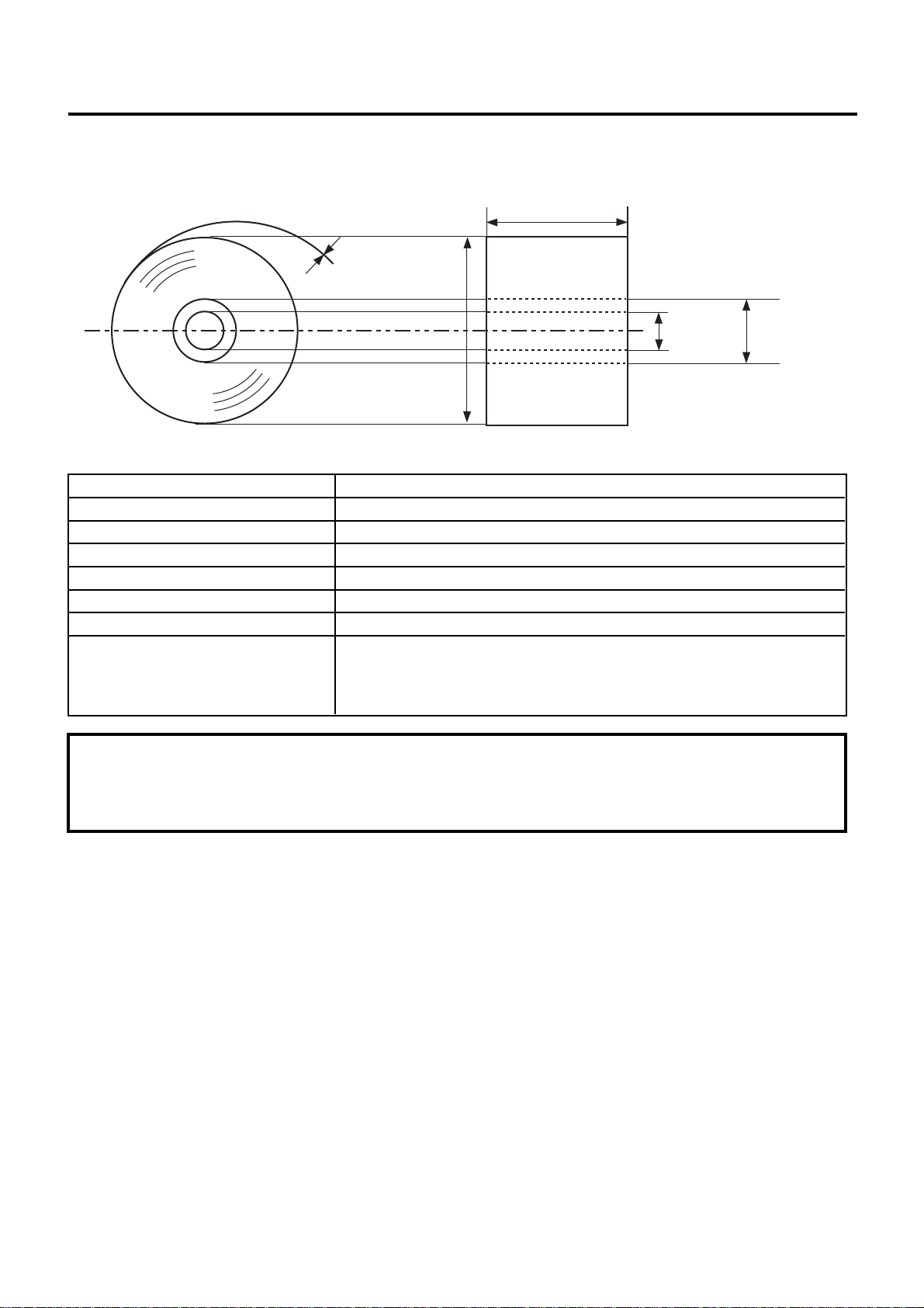
2.4 Thermal Paper Roll for the Thermal Printer
Width (W)
Paper
thickness (T)
EO1-12027
2.4 Thermal Paper Roll for the Thermal Printer
Inner core
diameter (ID)
Outer
diameter (D)
Outer core
diameter (OD)
Paper Type Thermal paper rolled with the print side facing outside.
Width (W) 80 +0/-1 mm
Outer diameter (D) 80 +0.5/-1 mm
Paper thickness (T) 0.075 ±0.005 mm
Weight 69±3g/m
2
Outer core diameter (OD) 18 mm
Inner core diameter (ID) 12 mm
Recommended Thermal paper Paper rolled onto a core are acceptable, however, the paper end should
not be pasted to the core.
Normal paper: PD150R OHJI PAPER (Japan)
Highly storable paper: PD152R OHJI PAPER (Japan)
CAUTION!
Use only paper which meet specified requirements. Use of non-specified paper may shorten the head life of printer,
result in problems with print quality, or cause a paper feed failure.
All paper should be handled with care to avoid any damage to the paper. Read the following guideline carefully.
• Do not store the paper for longer than the manufacture’s recommended shelf life.
• Store the paper in a cool, dry place. Avoid areas where they would be exposed to direct sunlight, high temperature,
high humidity, dust or gas.
• A contact of chemical or oil may discolor or erase the record.
• Rubbing the paper hard with nail or hard metal may discolor the paper.
For further information please contact your authorised TOSHIBA TEC represrntative or authorised paper manufacturer.
2-4

3. OVERVIEW
3. OVERVIEW
3.1 Front/Rear View
EO1-12027
3.1 Front/Rear View
<Front View>
Journal Window
Receipt Outlet
Validation Slot
Ribbon Cover
Receipt Cover
Remote Indicator Unit
TFT Display (option)
Operation Panel
Control Lock
PC Keyboard Connector
Magnetic Card Reader (option)
(see NOTE 2 below)
Drawer
(see NOTE 3 Below)
HDD Active LED
Power Switch
3.5" FDD
Keyboard
(see NOTE 4 below)
NOTES: 1) The above figure shows 2-station dot printer type.
2) Some models are provided with the Remote Indicator Unit as standard.
3) Some models are provided with the Drawer as standard.
4) Some models are provided with the 3.5" FDD as standard.
5) As the power cord is not provided for this product, please purchase it locally. For detail specifications,
please contact your nearest authorised TOSHIBA TEC representative.
6) A 3.5-inch hard disk drive is optional part for the ST-6400 standard models.
Power Cord
(see NOTE 5 below)
3-1

3. OVERVIEW
<Rear View>
EO1-12027
3.1 Front/Rear View
AC Outlet
Cable Clamp for LAN Cable
DRW2 DRW1
LAN LAN LED
Reset Switch
AC IN
P24V
SIO2
MOUSE LPT1
KB COM1COM3COM4
USB 1
USB 2
SIO1
PCI Slot
PCI Slot
VGA
COM2
Speaker Volume
AC Outlet Connector for the AC outlet, used for the CRT power supply.
AC Inlet Connector for the AC inlet.
P24V To this DC24V line connector, the power cable of the printer installed in the ST-6400
is connected.
DRW1·2 A 24V type drawer (DRWST-64, etc) is connectable. The drawer included in the ST-
6400 as standard is connected to the DRW1.
MOUSE Connector for the PS-2 type mouse.
KB To this connector, the PS-2 type keyboard installed in the ST-6400 is connected.
COM1 D-sub 9-pin male type connector (without power supply). The LS-770/780 slot scanner,
modem, serial Interface type scale, EFT, etc. are connectable.
COM2 D-sub 9-pin male type connector (without power supply). The LS-770/780 slot scanner,
modem, serial Interface type scale, EFT, etc. are connectable.
COM3 D-sub 9-pin female type connector (with +5V, +12V output). The LIUST-51/53, RS-
232C type hand scanner (HS-530) are connectable.
COM4 D-sub 9-pin female type connector (with +5V, +12V output). The LIUST-51/53, RS-
232C type hand scanner (HS-530) are connectable.
SIO1·2 Equivalent to COM3 and COM4 (D-Sub 9-pin female).
VGA Connector for the CRT.
LPT1 This is a Centronics interface connector, to which the printer cable of the PC standard
printer installed in the ST-6400 is connected.
USB 1, 2 Connector for the USB(Universal Serial Bus) I/F. USB Mouse, USB Keyboard, etc. can
be connected to these connectors.
LAN Modular type connector for the 10BASE-T/100BASE-TX LAN interface.
Speaker Volume Used to adjust the speaker volume. When turned to left, the sound volume decreases.
When turned to right, the sound volume increases.
Reset Switch Pressing this switch while the ST-6400 is hung-up resets the unit.
PCI Slot Slots for installing the PCI board. Maximum of 2 boards can be installed.
Installable board size: Lower slot (PCI1) 140 mm 1 board
Upper slot (PCI2) 185 mm 1 board
Cable Clamp for The LAN cable is fixed with this cable clamp to prevent the cable being caught in the
LAN Cable Rear Cover.
3-2

3. OVERVIEW
3.2 Control Lock and Mode Selector Keys
Control Lock Mode Selector Keys
S
MA
EO1-12027
3.2 Control Lock and Mode Selector Keys
X
REG
1
(8) (7)
4
3
2
5
6
3.3 Operation Panel
3.3.1 2-station Dot Printer Type
ST-6400
* The key can be inserted or removed at Position 1 or 2.
JOURNAL
RECEIPT
PAPER OUT VALI
MA Key S Key
MA
RECEIPT
FEED
JOURNAL
S
REG Key
PRINTER
REG
POWER
X Key
X
POWER LED: Green
Lights: The power is supplied.
Extinguished: The power is not supplied.
PRINTER LED: Green
Lights: The printer is ready to print. (on-line mode)
Extinguished: The printer is not ready to print. (off-line mode)
VALI LED: Green
Lights: Validation mode
Extinguished: Receipt/journal mode
Blinks: Waiting for validation paper.
RECEIPT/JOURNAL PAPER OUT LED: Red
Lights: Detects that receipt/journal paper has almost run out.
Extinguished: Not detect that receipt/journal paper has almost run out. (Usual status)
PRINTER Switch
This switch is used to select on-line or off-line. In on-line mode, printing is performed in usual mode.
When off-line mode is selected, the printer stops printing after printing the line being printed.
RECEIPT/JOURNAL FEED Switch
This switch is used to feed receipt/journal paper. This switch is effective only when the PRINTER LED is turned
off (off-line mode).
3-3

3. OVERVIEW
3.3.2 Single Station Thermal Printer Type
EO1-12027
3.3 Operation Panel
ST-6400
ERROR
PAPER OUT
PRINTER
PAPER
FEED
POWER
POWER LED: Green
Lights: The power is supplied.
Extinguished: The power is not supplied.
PAPER FEED Switch
Pressing this switch for a short time feeds the paper by one line. Holding it down feeds the paper continuously.
ERROR LED: Red
Indicates different errors by lighting or blinking.
Error Display Pattern Resetting Method
Printer cover open Illuminated Close the cover.
Head up Illuminated CLose the printing head.
Memory check Disabled
Head overheat Automatically reset by temperature
Macro execution wait Press the PAPER FEED switch.
Cutter motorlock Remove jammed paper.
PAPER OUT LED: Red
Illuminated when the paper nearly runs out. (Stops after printing the set length)
drop.
3-4

4. FLOPPY DISK AND FLOPPY DISK DRIVE (with FDD Model)
4.1 Floppy Disk Write Protection
EO1-12027
4. FLOPPY DISK AND FLOPPY DISK DRIVE (with FDD Model)
CAUTION!
When handling a floppy disk, care should be taken as follows:
• Do not place the floppy disk close to any magnetic product.
• Do not use a damaged floppy disk.
• Do not bend the floppy disk.
• Keep the floppy disk away from water.
• Do not expose the floppy disk to direct sunlight.
4.1 Floppy Disk Write Protection
The Floppy Disk contains the program to run the ST-6400. Before using this disk, make absolutely sure to write
protect the disk to prevent accidental overwrite.
• How to Write Protect the Floppy Disk
Slide the Write Protect Tab on the reverse side of the Floppy Disk downward to open the Write Protection Hole.
Write Protection Hole
Write Enable
Wite Protect
Write Protect Tab
• How to cancel the Write Protect
Slide the Write Protect Tab upward to close the Write Protection Hole.
4.2 Handling the Floppy Disk Drive
The Floppy Disk drive reads and writes data via the Floppy Disk by rotating the disk at a high speed.
There are two read/write heads (multiple) in the drive. The heads touch both sides of the disk to perform read or write
function.
3.5-inch Floppy Disk Drive
FDD Active LED
FDD Active LED: Lit when the Floppy Disk drive reads or writes data in the Floppy Disk.
4-1
Eject Button

4. FLOPPY DISK AND FLOPPY DISK DRIVE (with FDD Model)
4.2.1. Loading the Floppy Disk
1) Unlock the FDD Cover to open by pressing the left side of the FDD Lock.
FDD Cover Key
FDD Cover
2) Insert the Floppy Disk gently with the label side up until it clicks.
EO1-12027
4.2 Handling the Floppy Disk Drive
4.2.2. Ejecting the Floppy Disk
CAUTION!
Do not press the eject button while the active LED is lit. Doing so may destroy the data in the floppy disk.
Press the Eject Button on the Floppy Disk Drive. The Floppy Disk pops out to the position where it can be
removed by hand.
Eject Button
4-2

5. HANDLING OF THE PRINTER (2-station Dot Printer Type)
5.1 Removing the Reciept Cover
EO1-12027
5. HANDLING OF THE PRINTER (2-station Dot Printer Type)
5.1 Removing the Reciept Cover
Remove the Receipt Cover when the Receipt or Journal Paper Roll is replaced with a new one or when the Store
Name/Message Stamp must be replenished with the Ink.
5.1.1 Removing the Receipt Cover
1) Insert the Cover Lock Key into the Cover Lock and turn it 90 degrees clockwise to unlock.
Receipt Cover
Cover Lock Key
2) Remove the Receipt Cover by lifting both edges of the Receipt Cover.
Receipt Cover
5.1.2 Attaching the Receipt Cover
1) Align the hooks on the rear of the Receipt Cover with the notches in the lower cover. Then, push down the front
side of the Receipt Cover until it clicks, and lock the receipt cover with the key.
Receipt Cover
5-1
Hook

5. HANDLING OF THE PRINTER (2-station Dot Printer Type)
5.2 Removing the Ribbon Cover
Remove the Ribbon Cover when the Ribbon Cassette must be replaced.
5.2.1 Removing the Ribbon Cover
1) Remove the Receipt Cover. (Refer to "Removing the Receipt Cover.")
2) Remove the Ribbon Cover by lifting the left edge of the Ribbon Cover.
Ribbon Cover
EO1-12027
5.2 Removing the Ribbon Cover
5.2.2 Attaching the Ribbon Cover
1) Align the tabs on the front of the Ribbon Cover with the holes in the Top Cover. Then, push down the rear
side of the Ribbon Cover until it clicks.
Ribbon Cover
5-2

5. HANDLING OF THE PRINTER (2-station Dot Printer Type)
5.3 Installing/Replacing the Reciept Roll
5.3.1 Installing the Receipt Roll
1) Remove the Receipt Cover. (Refer to "Removing the Receipt Cover.")
2) Cut the paper end to make it straight.
EO1-12027
5.3 Installing/Replacing the Reciept Roll
3) Put the Receipt Roll in the left holder so that the paper will be fed from the bottom of the Paper Roll.
4) Insert the paper end into the paper slot until it stops, then feed the paper by pressing the [RECEIPT FEED] Switch.
5) Attach the Receipt Cover with the paper end coming out of the receipt outlet. (Refer to "Attaching the Receipt
Cover.")
5-3

5. HANDLING OF THE PRINTER (2-station Dot Printer Type)
5.3.2 Replacing the Receipt Roll
1) Remove the Receipt Cover. (Refer to "Removing the Receipt Cover.")
2) Pull up the Green Lever on the receipt side.
Green Lever
EO1-12027
5.3 Installing/Replacing the Reciept Roll
3) Remove the remaining paper roll from the rear of the printer.
4) Press down the green lever on receipt side.
Green Lever
5) Install a new paper roll according to steps 2) to 5) of the procedure "Installing the Receipt Roll."
5-4

5. HANDLING OF THE PRINTER (2-station Dot Printer Type)
5.4 Installing/Replacing the Journal Roll
5.4 Installing/Replacing the Journal Roll
5.4.1 Installing the Journal Roll
1) Follow Steps 1) and 2) for "Installing the Receipt Roll" in the preceding section.
2) Put the Journal Roll in the right holder so that the paper will be fed from the bottom of the Paper Roll.
EO1-12027
3) Insert the paper end into the paper slot until it stops, then feed the paper by pressing the [JOURNAL FEED]
Switch until the leading edge of the journal comes out about 25 cm.
4) Insert the paper end into the slit in the Take-up Reel and wind it around the reel two or three times. Then, place
the Take-up Reel on the Take-up Holder.
Take-up Reel
Take-up Reel
Take-up Holder
5) Turn the Take-up Reel rearward until slack in paper is taken out.
6) Attach the Receipt Cover. (Refer to "Attaching the Receipt Cover.")
5-5

5. HANDLING OF THE PRINTER (2-station Dot Printer Type)
5.4 Installing/Replacing the Journal Roll
5.4.2 Replacing the Journal Roll
1) Remove the Receipt Cover. (Refer to "Removing the Receipt Cover.")
2) Cut the Journal Paper as shown in the figure.
3) Pull up the Green Lever on the journal side ( 1 ). Lift the Take-up Reel to remove paper ( 2 ).
EO1-12027
4) Press down the Green Lever on journal side.
Take-up Reel
Green Lever
2
1
Green Lever
5) Install a new paper roll according to steps 1) to 6) of the procedure "Installing the Journal Roll."
5-6

5. HANDLING OF THE PRINTER (2-station Dot Printer Type)
5.5 Setting/Replacing the Ribbon Cassette
EO1-12027
5.5 Setting/Replacing the Ribbon Cassette
5.5.1 Setting the Ribbon Cassette
1) Remove the Receipt Cover and the Ribbon Cover. (Refer to "Removing the Receipt Cover." and "Removing the
Ribbon Cover.")
2) Push down the Ribbon Cassette until it clicks.
Ribbon Cassette
3) Turn the knob of the Ribbon Cassette in the direction of the arrow several times to remove any slack in the ribbon.
Ribbon Cassette
Knob
4) Attach the Ribbon Cover and the Receipt Cover. (Refer to "Attaching the Ribbon Cover." and "Attaching the
Receipt Cover.")
5.5.2 Replacing the Ribbon Cassette
1) Remove the Receipt Cover and the Ribbon Cover. (Refer to "Removing the receipt cover." and "Removing the
Ribbon Cover.")
2) Remove the old Ribbon Cassette by lifting if from the right front side so that it does not make contact with the Top
Cover.
Ribbon Cassette
3) Set a new Ribbon Cassette according to steps 2) to 4) of the procedure "Setting the Ribbon Cassette."
5-7

5. HANDLING OF THE PRINTER (2-station Dot Printer Type)
5.6 Replenishing the Store Name/Message Stamp with Ink
EO1-12027
5.6 Replenishing the Store Name/Message Stamp with Ink
When the Store Name/Message Stamp is installe and printing appears too light, replenish the ink in the following
procedure.
1) Remove the Receipt Cover. (Refer to "Removing the Receipt Cover.")
2) Remove the Store Name/Message Stamp by pulling it as shown in the figure.
Store Name/Message Stamp
3) Apply only two or three drops of ink. The stamp may not print dark immediately. Allow time for ink to saturate
the stamp.
Stamp Ink
Store Name/Message Stamp
4) Install the stamp by inserting it in the direction of the arrow until it clicks.
Store Name/Message Stamp
5-8

6. HANDLING OF THE PRINTER (Single Station Thermal Printer Type)
6.1 When using the Auto Loading Function
EO1-12027
6. HANDLING OF THE PRINTER
(Single Station Thermal Printer T ype)
A thermal receipt printer is provided on this unit. (A thermal printer prints thermal receipt paper by applying heat to
the paper to react with the chemicals on the paper surface.)
WARNING!
1. There is a Cutter Blade inside. Do not touch and disassemble this cutter block.
2. After printing, the thermal head may become very hot. Do not touch the thermal head to
avoid burning your fingers.
CAUTION!
1. Do not subject the thermal receipt paper to water, oil, or heat source as this will darken the paper.
2. Do not open the printer cover during printing.
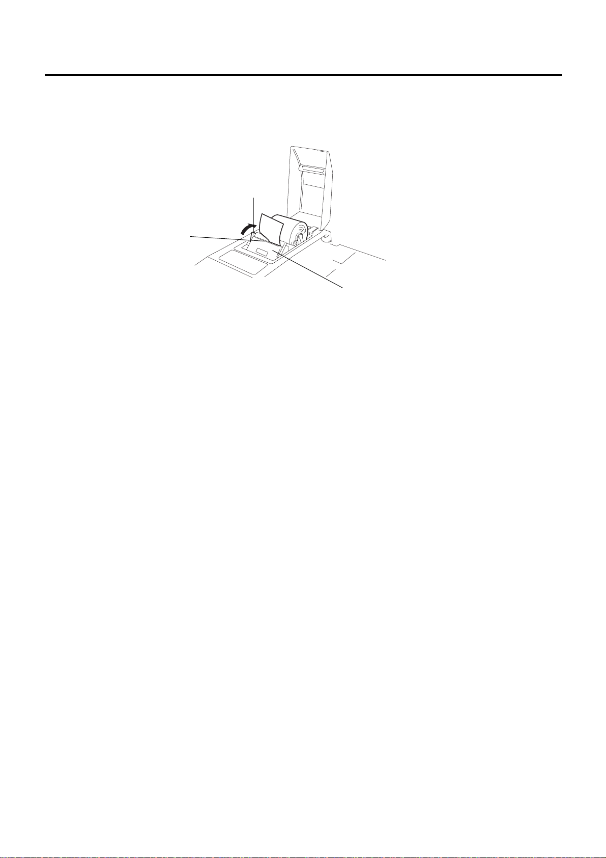
6.1 When using the Auto Loading Function
1) Open the Printer Cover.
2) Move the Head-up Lever in the direction of the arrow to raise the Printing Head.
Printer Cover
Head-up Lever
Auto Cutter
3) Cut the end of the paper straight with a pair of scissors. Do not insert the paper into the printer with its end
fluffed or bent.
Good NG
6-1
NG
NG
6. HANDLING OF THE PRINTER (Single Station Thermal Printer Type)
6.1 When using the Auto Loading Function
4) Confirm the winding direction of the Paper Roll. Spread the Paper Holder and fit the protrusions into the
paper core properly.
Paper Holder
Protrusion
EO1-12027
5) Insert the end of the paper straight into the paper slot of the printer and close the Printing Head. The paper
is automatically pulled in by a constant length.
Printing Head
Paper Slot
Head-up Lever
NOTE: When the inserted paper skews, remove the paper by pulling up the Head-up Lever, raising the
Printing Head, and rotating the Paper Feed Knob. Then, reinsert the paper.
Head-up Lever
6) Close the Printer Cover to finish setting of the Paper Roll.
6-2
Paper Feed Knob

6. HANDLING OF THE PRINTER (Single Station Thermal Printer Type)
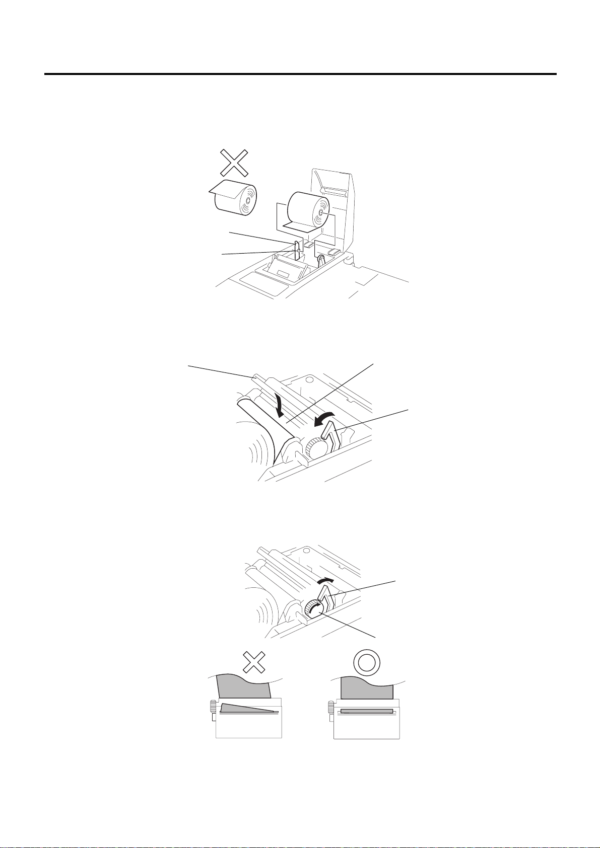
6.2 When using the Manual Loading Function
6.2 When using the Manual Loading Function
CAUTION!
Auto Loading is selected as default. If you want to change it to the manual set, please contact your nearest
TOSHIBA TEC service representative.
1) Open the Printer Cover.
2) Move the Head-up Lever in the direction of the arrow to raise the Printing Head.
Printer Cover
Head-up Lever
Auto Cutter
EO1-12027
3) Insert the end of the paper into the Paper Slot, turn the Paper Feed Knob in the direction of the arrow until
the paper end comes out of the auto cutter's paper outlet for about 5cm.
Paper Slot
Paper Feed Knob
Auto Cutter
Paper Outlet
4) When the paper is tilting, correct it and close the Printing Head.
6-3
6. HANDLING OF THE PRINTER (Single Station Thermal Printer Type)
6.2 When using the Manual Loading Function
5) Move the Head-up Lever in the direction of the arrow to close the Printing Head. Cut off the surplus paper
at the edge of the paper outlet of the auto cutter.
Head-up Lever
Paper Outlet
Auto Cutter
6) Close the Printer Cover. The Paper Roll loading has been completed.
EO1-12027
7) To take out the end of the paper, pull it out straight while the Printing Head is opened.
6-4

7. DISPLAY (LIUST-51)
7. DISPLAY (LIUST-51)
EO1-12027
7. DISPLAY (LIUST-51)
This LIUST-51 is a dot fliorescent display for ANK indication with 20 digits in 2 lines, connected to the ST-6400 POS
Terminal. It has a built-in controller and connects to the Control Unit of the ST-6400 with the I/O serial interface (RS232C or equivalent). It is normally supplied as a stand type, but can be modified to a pole type which are integrated
into the ST-6400 terminal.
Stand Type
Display Section
Base
<Overview of Display Section>
Cable
Display Section
Pole Type
Neck (Ø 34mm)
POLST-51
<Display Angle Adjustment>
This line display can be adjusted in vertical (tilt) and horizontal (swivel) direction so that the operator or
customer can see it easily.
Tilt direction
10 to 42 degrees above the horizontal
level (8° x 4 steps)
Swivel direction
165 degrees on either side from the
center (15° x 22 steps)
7-1

8. DRAWER
8.1 Manual Drawer Release and Lock
EO1-12027
8. DRAWER
WARNING!
When opening the drawer, be careful not to let the drawer hit any person.
This drawer can be used both as an integrated drawer into the ST-6400 terminal, and as a separate remote drawer.
Drawer Cable
Media Slot
Drawer Release Lock
8.1 Manual Drawer Release and Lock
The drawer opens automatically when a registration is performed. In the event of a power failure or other trouble, the
drawer can be opened manually in the following manner.
8.1.1 Releasing
Insert the Drawer Release Key into the Drawer Release Lock, then turn the key clockwise. The drawer will now
open. The Drawer Release Key can be taken out by returning it to the original position.
Drawer Release Key
Drawer Release Lock
8.1.2 Locking
When the drawer is closed, it is automatically locked and will not open without the Drawer Release Key or
transaction entries.
8-1
8. DRAWER
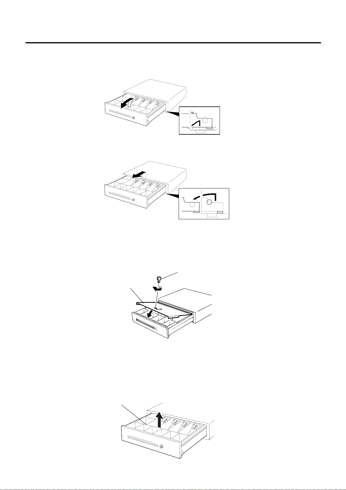
8.2 Removing the Drawer
1) Pull the drawer out, and when it stops by the stopper, lift the drawer up and pull it again.
2) When it stops again by the roller fixed in the drawer case, lift it and pull it again.
EO1-12027
8.2 Removing the Drawer
8.3 Locking the Cash Drawer Cover (CDC)
8.3.1 Locking
Push the Cash Drawer Cover to the back of the drawer. Then, press the cover lightly, insert the key into the
key hole in the cover, and turn it to lock.
Cash Drawer Cover Key
Cash Drawer Cover
8.3.2 Unlocking
Unlock the cover using the key, and lift the front end.
8.4 Changing the Layout of the Money Case
1) Open the drawer, then take the Money Case out.
Money Case
8-2

8. DRAWER
8.4 Changing the Layout of the Money Case
2) Remove the Coin Case from the Money Case.
Coin Case
Money Case
3) To remove the Partition from the Coin Case, pull the Partition upward while pushing the Coin Case outward.
Partition
EO1-12027
Coin Case
4) Set the Partition in the groove of the place where you like to set, then push the Partition downward.
Partition
Coin Case
5) To change the layout of the Bill Case, it is necessary to remove the Bill Holder. To remove the Bill Holder,
insert the tip of the phillips screwdriver in the back of the Bill Holder, then push the phillips screwdriver
downward. To remove the Partition, pull the front of the Partition upward.
Bill Holder
Phillips Screwdriver
8-3
Bill Holder

8. DRAWER
8.5 Media Slot
The Media Slot provided at the front of the drawer is used to put non-cash media such as check in the drawer
without opening it. The non-cash media put from this slot are kept under the Money Case, therefore you can
keep them in secret.
EO1-12027
8.5 Media Slot
Media Slot
Money Case
Non-cash media are kept here.
8-4

9. GENERAL MAINTENANCE
EO1-12027
9.1 Cleaning
9. GENERAL MAINTENANCE
9.1 Cleaning
WARNING!
1. Be sure to disconnect the power cord prior to performing any maintenance.
2. Do not pour water directly on or wipe the operator’s/Customer's display with a soaked cloth,
as this may cause fire, electric shock, or machine failure.
CAUTION!
1. Never use an organic solvent like thinners or benzene for cleaning. Using such solvents may
discolor the covers.
2. Do not use any sharp object to clean the operator’s/Customer's display. Doing so may cause
an operator’s/Customer's display failure.
To help retain the high quality and performance of your POS Terminal, it should be cleaned regularly.
The greater the usage on the POS Terminal, the more frequent the cleaning. (i.e. low usage = weekly: high usage
= daily)
• Cleaning the Operator’s Display
Clean the surface of the operator’s display with a soft dry cloth or with an electrostatic free cleaner for automated office equipment.
• Cleaning the Covers
Wipe the covers with a soft dry cloth or soft cloth slightly moistened with mild detergent. After using detergent
for cleaning, be sure to wipe it off with a slightly moistened cloth.
9-1

10. TROUBLESHOOTING
10. TROUBLESHOOTING
10. TROUBLESHOOTING
WARNING!
If you cannot solve a problem with the following solutions, do not attempt to repair it yourself.
Turn the power off, unplug the POS Terminal, then contact your TOSHIBA TEC representative for
assistance.
Symptom Check Point Solution
The power does not turn on. • Is the power cord plugged in • Plug in correctly.
correctly?
• Is the power supplied to the AC • If it is not a power failure, check
outlet? for the power supply to the AC
outlet with another electric
appliance. When the power is
not supplied, contact your
nearest power company.
• Has the fuse or circuit breaker • Check the fuse or circuit breaker.
blown?
Registration cannot be performed. • Is the key position set correctly? • Set the key position correctly.
EO1-12027
Receipt paper is not issued. • Is the receipt roll loaded • Refer to page 5-3 (Dot Printer
properly? Type) or 6-1 (Thermal Printer
Type) and load the receipt roll
properly.
• Is the printer jammed with the • Remove the jammed receipt, and
receipt? reload the receipt roll.
Journal paper is not taken up. • Is the journal roll loaded • Refer to page 5-5 and load the
properly? journal roll oroperly.
10-1

PRINTED IN JAPAN
E
EO1-12027 0106500 D
 Loading...