

Page 1

PRINTED IN JAPAN
TEC Color Printer
CB-416/426-T3 SERIES
Original Aug., 1998
(Revised Mar., 1999)
Document No. EO18-33002A
Maintenance Manual
Page 2

TABLE OF CONTENTS
1. UNPACKING ...........................................................................................1- 1
1.1 PROCEDURE..................................................................................1- 1
1.2 CHECKS..........................................................................................1- 2
2. MAIN UNIT REPLACEMENT ..................................................................2- 1
2.1 REPLACING THE CPU PC BOARD ...............................................2- 2
2.2 REPLACING HCHK PC BOARD.....................................................2- 3
2.3 REPLACING THE DRIVER PC BOARD .........................................2- 4
2.4 REPLACING HWC PC BOARD ......................................................2- 6
2.5 REPLACING PDM PC BOARD .......................................................2- 7
2.6 REPLACING THE PS UNIT ............................................................2- 8
2.7 REPLACING THE PLATEN MOTOR AND FEED MOTOR.............2- 9
2.8 REPLACING THE RIBBON MOTOR ASS'Y ...................................2-10
2.9 REPLACING THE SOLENOID ASS'Y.............................................2-11
2.10 REPLACING THE PRINT HEAD.....................................................2-12
2.11 REPLACING THE PLATEN AND MEDIA SENSOR .......................2-13
2.12 REPLACING THE PINCH ROLLER ASS'Y.....................................2-14
2.13 DIP SWITCH SETTINGS ................................................................2-15
3. INSTALLATION PROCEDURE FOR OPTIONAL EQUIPMENT ............3- 1
3.1 CUTTER MODULE (CB-1204-QM) .................................................3- 1
3.2 RIBBON MODULE (CB-1004-QM)..................................................3- 3
3.3 PRINT HEAD FAN...........................................................................3- 5
4. TROUBLESHOOTING.............................................................................4- 1
5. DIAG. TEST OPERATION.......................................................................5- 1
5.1 OUTLINE OF THE DIAG. TEST OPERATION................................5- 1
5.2 SELF TEST MODE..........................................................................5- 2
5.3 PARAMETER SETTING MODE......................................................5-10
5.4 TEST PRINT MODE........................................................................5-43
5.5 RAM CLEAR MODE........................................................................5-51
6. PROGRAM DOWNLOAD........................................................................6- 1
6.1 FLOPPY DISK .................................................................................6- 1
6.2 SETUP.............................................................................................6- 1
6.3 OUTLINE OF THE PROGRAM DOWNLOAD PROCEDURE .........6- 1
6.4 DOWNLOAD PROCEDURE ...........................................................6- 1
EO18-33002A
(Revision Date: Dec. 20, 2000)
CAUTION:
1. This manual may not be copied in whole or in part without prior written permission of TOSHIBA
TEC.
2. The contents of this manual may be changed without notification.
3. Please refer to your local Authorized Service representative with regard to any queries you may
have in this manual.
Page
Copyright © 2000
by TOSHIBA TEC CORPORATION
All Rights Reserved
570 Ohito, Ohito-cho, Tagata-gun, Shizuoka-ken, JAPAN
Page 3

1-1
1. UNPACKING
EO18-33002A
1.1 PROCEDURE
1. UNPACKING
1.1 PROCEDURE
1) Open the carton.
2) Unpack the accessories from the carton.
3) Unpack the printer and remove the side pads (L) and (R).
4) Place the printer on a level surface.
Media Side
Black Screw
Partition
Supply Roll Holder Pad (L)
Supply Roll Holder
Supply Roll Holder Pad (R)
Carton
Carton
Side Pad (R)
Band
Owner's Manual
Power Cord
Fan Filter
Feed Roller Brush
Print Head Cleaner
Side Pad (L)
Printer
Rear Pad
Bottom Pad
Fig. 1-1
Page 4

1-2
1. UNPACKING
EO18-33002A
1.2 CHECKS
6) Remove the six pieces of tape to open the top cover and remove the rear pad.
7) Remove the 12 pieces of tape from the internal parts.
8) Turn all of the head levers to the OPEN position to open the pinch roller ass'y and remove the sheet
of paper protecting the print heads.
9) Turn all of the head levers to the LOCK position to close the pinch roller ass’y, then lower the pinch
roller lever to the ROLLER LOCK position.
10) Close the top cover.
NOTES: 1. Regarding attachment of the accessories, refer to the Owner's Manual.
2. The above illustration is for the CB-416-T3-QQ/QP model. Since the CB-426-T3-QQ/QP
model is a two-color printer, the two print head blocks to the right hand are not installed.
Please accept that all illustrations provided in this manual hereafter are for the CB-416T3-QQ/QP.
1.2 CHECKS
1) Check for damage or scratches on the machine.
2) Confirm that none of the accessories are missing.
NOTES: 1. Keep the cartons and pads for future transportation of the printer.
2. If the printer is to stand unused for a long period of time or if it is to be transported, be sure
to insert a sheet of paper under all the print heads and the pinch roller to protect the print
heads.
Tape
Tape
Tape
Rear Pad
Fig. 1-2
Tape
Tape Pinch Roller Ass'y
Head Lever
Tape
Tape
Pinch Roller Lever
Fig. 1-3
Pinch Roller
CB-416: Print Head (Yellow)
CB-426: 2nd Print Head
CB-416: Print Head (Cyan)
CB-426: 1st Print Head
CB-416: Print Head (Magenta)
CB-426: Not installed
CB-416: Print Head (Black)
CB-426: Not installed
Page 5

2-1
2. MAIN UNIT REPLACEMENT
EO18-33002A
2. MAIN UNIT REPLACEMENT
2. MAIN UNIT REPLACEMENT
CAUTION:
Never remove the red screws. Doing so will change the adjustment.
1) Turn the power off.
2) Open the top cover and remove all of the ribbon module.
3) Remove the four B-3x6 screws and five B-4x6 screws securing the left side cover, detach the fan
motor connectors (CN3 and CN4) then remove the left side cover.
4) Remove the two B-4x6 screws securing the operation panel and disconnect the CN40 and CN51
connectors from the driver PC board, then remove the operation panel.
NOTE: Instructions for opening the top cover and removing the left side cover and operation panel are
omitted from each removal/installation procedure provided below.
CAUTION:
1. Lubrication: During parts replacement
2. Kinds of oil: FLOIL G-488: 1Kg can. (Part No. 19454906001)
3. Do not spray the inside of the printer with lubricants. Unsuitable oil can damage the mechanism.
All machines are generally delivered in their best condition. Efforts should be made to keep them that
way. Lack of oil, or the presence of debris or dust, may cause an unexpected failure. To maintain in
optimal operation condition, periodically clean the machine and apply the proper kinds of oil to each part
in which lubrication is needed.
Although the frequency of lubrication varies according to how often the machine is used, as a minimum
it is necessary to lubricate before any part becomes dry. It is also necessary to wipe off excessive oil
or it will collect dirt.
WARNING!
Disconnect the power cord before replacing the main parts.
LUBRICATION
Left Side Cover
Top Cover
B-3x6 Screw
Operation Panel
B-4x6 Screw
Fan Motor
B-4x6 Screw
B-4x6 Screw
Fig. 2-1
Page 6

2-2
2. MAIN UNIT REPLACEMENT
EO18-33002A
2.1 REPLACING THE CPU PC BOARD
2.1 REPLACING THE CPU PC BOARD
1) Disconnect all connectors from the CPU PC board.
2) Remove the three SMW-3x6 screws (small washer type) and four SMW-3x6.
3) Remove the CPU PC board from the driver PC board.
4) Replace the CPU PC board with a new one, and then reassemble in the reverse order of removal.
Refer to the following DIP SW function table and set the serial interface specifications.
CPU PC Board
Fig. 2-2
DIP SW
SMW-3x6
Screw
SMW-3x6 Screw
(Small Washer Type)
SMW-3x6
Screw
NOTE: The shaded settings are the factory default settings. "OFF" means "OPEN".
■ DIP SW
This DIP switch is provided on the CPU PC board. Even after installing the CPU PC board, it is
accessible from the rear of the printer by removing the DIP SW cover.
.oNFFO/NOnoitcnuF
1
2
12
deepsnoissimsnarT
FFOFFOSPB0042
NOFFOSPB0084
FFO NO SPB0069
NONOSPB00291
3
FFO tib1
htgneltibpotS
NOstib2
4
FFOstib7
htgnelataD
NO stib8
5
FFO tuohtiW
kcehcytiraP
NO htiW
6
FFO NEVE
PIDnehwevitceffe(kcehcytiraP
).NOottessi5#WS
NODDO
7
8
78
locotorpataD
FFOFFO
).emitnorewopehttatuptuosiNOXoN(FFOX/NOX
).emitfforewopehttatuptuosiFFOXoN(
NOFFO
)ATD(YSUB/YDAER
).emitnorewopehttatuptuosiNOXoN(
).emitfforewopehttatuptuosiFFOXoN(
FFO NO
YSUB/YDAER+FFOX/NOX
).emitnorewopehttatuptuosiNOX(
).emitfforewopehttatuptuosiFFOX(
NONO
).emitnorewopehttatuptuosiNOX(FFOX/NOX
).emitfforewopehttatuptuosiFFOX(
Page 7
2-3
2. MAIN UNIT REPLACEMENT
EO18-33002A
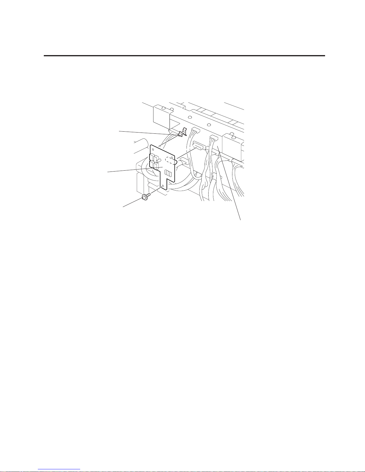
2.2 REPLACING THE HCHK PC BOARD
2.2 REPLACING THE HCHK PC BOARD
1) Remove the SMW-3x6 screw from the HCHK PC board.
2) Release the HCHK PC board from the locking support.
Locking Support
Fig. 2-3
3) Replace the HCHK PC board with a new one, and then reassemble in the reverse order of removal.
SMW-3x6 Screw
Driver PC Boared
HCHK PC Board
Page 8

2-4
2. MAIN UNIT REPLACEMENT
EO18-33002A
2.3 REPLACING THE DRIVER PC BOARD
1) Remove the CPU PC board. (See Section 2.1.)
2) Disconnect all connectors from the driver PC board.
3) Remove the four SMW-4x8 screws to detach the driver PC board from the printer.
4) After replacing the driver PC board with a new one, refer to the following [CHECK] and [ADJUSTMENT]
and reassemble in the reverse order of removal.
1. Set the DIP switches on the new driver PC board. (Refer to Section 2.13.)
2. Firmly connect the harnesses with the connectors by matching their colors on the driver PC board.
1. After replacing the driver PC board, be sure to adjust the media sensor voltage following the
procedure described on the next page.
2. Refer to the Owner’s Manual to readjust the media sensor sensitivity.
2.3 REPLACING THE DRIVER PC BOARD
CHECK
ADJUSTMENT
Fig. 2-4
SMW-4x8 Screw
SMW-4x8 Screw
WARNING!
Replace only with the same type and rated fuse for continued protection against risk of fire.
Driver PC Board
Page 9

2-5
2. MAIN UNIT REPLACEMENT
EO18-33002A
■ Adjusting the Media Sensor Voltage
After replacing the driver PC board, be sure to adjust the sensor voltage using the procedure below.
When adjusting the black mark sensor, place IJ16 tag paper (OSAKA SEALING) so that the sensor
can sense the print area of the tag paper. For the feed gap sensor adjustment, place IJKS labels
(OSAKA SEALING).
(1) Connect the printer to a PC and turn the power on for both.
(2) Adjust the media sensor voltage.
■ Black Mark Sensor
Fully turn the feed gap sensor adjustment knob on the rear of the printer counterclockwise.
Turn the black mark sensor adjustment knob so that the notch stops at a 180 degree angle.
Turn the VR3 on the driver PC board in either direction until all the black mark sensor lamps are
lit. If the lamps do not light, turn the black mark sensor adjustment knob within the angle range
of 150 degree to 210 degree, and retry.
■ Feed Gap Sensor
Fully turn the black mark sensor adjustment knob on the rear of the printer counterclockwise.
Turn the feed gap sensor adjustment knob so that the notch stops at a 90 degree angle.
Turn the VR4 on the driver PC board in either direction until the topmost feed gap sensor
lamp lights. If the lamp does not light, turn the feed gap sensor adjustment knob within the
angle range of 60 degree to 120 degree, and retry.
NOTE: Adjust the knobs so that they stop in the mid-range with all the lamps lit.
(3) After completing this procedure, turn the power off.
2.3 REPLACING THE DRIVER PC BOARD
ADJUSTMENT
GAP MARKER
VR4 VR3
IC22
CN10
IC23
IC24
CN11
TPGI
TPGR
B-CX DRIVER PWB
FMJD0004802
CN9
2 1
CN8
2 1.
33
Feed Gap Sensor Lamps
Black Mark Sensor Lamps
Green
Red
Notch
Black Mark Sensor Adjustment Knob
Feed Gap Sensor Adjustment Knob
Fig. 2-5
Driver PC Board
Rear of the Printer
Fig. 2-6
Fig. 2-7
150°
210°
180°
120°
60°
90°
GAP
GAP
MARK
MARK
VR3
VR4
MARK
GAP
Page 10

2-6
2. MAIN UNIT REPLACEMENT
EO18-33002A
2.4 REPLACING THE HWC PC BOARD
2.4 REPLACING THE HWC PC BOARD
1) Remove the CPU PC board. (See Section 2.1.)
2) Remove the driver PC board. (See Section 2.3.)
3) Disconnect all cables from the HWC PC board.
4) Remove the three SMW-3x6 screws (small washer type) and two SMW-3x6 screws to detach the
HWC PC board from the driver PC board.
Fig. 2-8
HWC PC Board
5) Replace the HWC PC board with a new one, and then reassemble in the reverse order of removal.
SMW-3x6 Screw
(Small Washer Type)
SMW-3x6 Screw
Page 11
2-7
2. MAIN UNIT REPLACEMENT
EO18-33002A
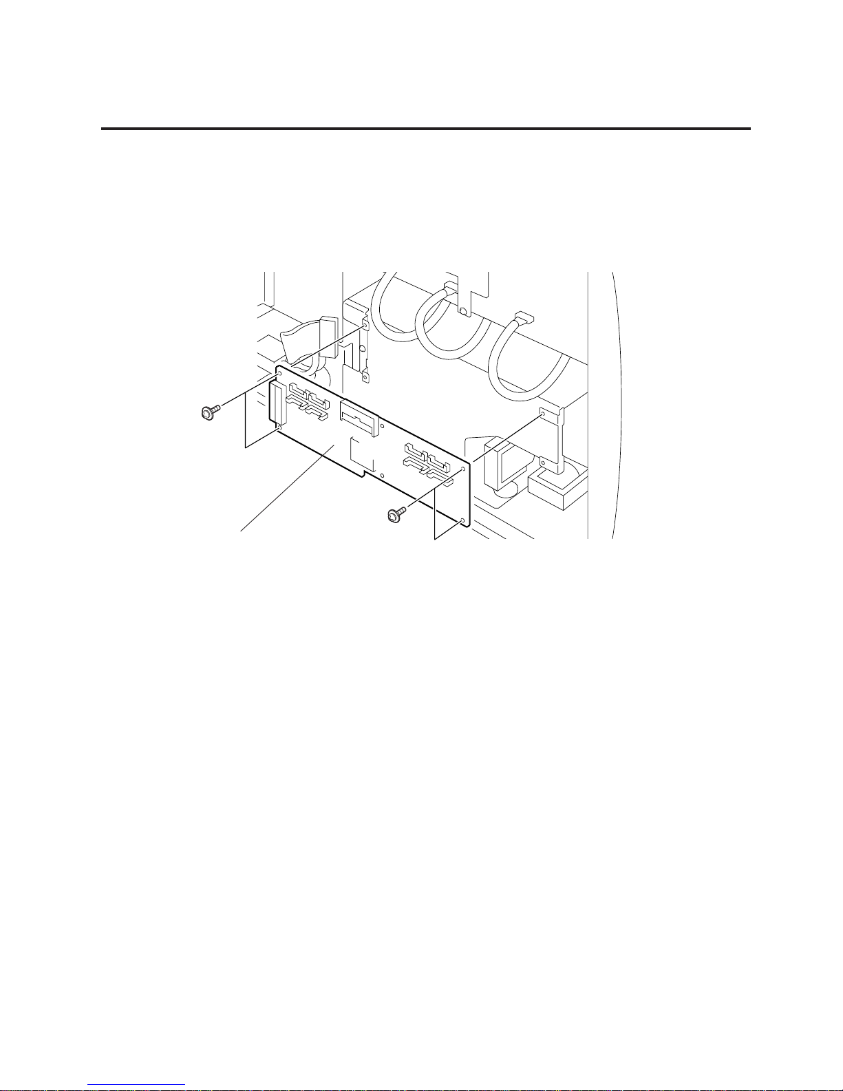
2.5 REPLACING THE PDM PC BOARD
1) Disconnect all cables from the PDM PC board.
2) Remove the four SMW-3x6 screws to detach the PDM PC board.
Fig. 2-9
PDM PC Board
2.5 REPLACING THE PDM PC BOARD
SMW-3x6 Screw
SMW-3x6 Screw
3) Replace the PDM PC board with a new one, and then reassemble in the reverse order of removal.
Page 12

2-8
2. MAIN UNIT REPLACEMENT
EO18-33002A
2.6 REPLACING THE PS UNIT
1) Disconnect the two cables from CN1 and CN2 on the PS unit.
2) Remove the five SMW-4x8 screws to detach the PS unit. Detach the PS cover by moving it in the
arrow-indicating direction.
3) Remove the N-3 nut and D-3x6 screw to remove the thermistor from the PS unit.
4) Replace the PS unit with a new one, and then reassemble in the reverse order of removal.
2.6 REPLACING THE PS UNIT
WARNING!
Replace only with the same type and rated fuse for continued protection against risk of fire.
PS Cover
Connector (CN2)
PS UNIT
SMW-4x8 Screw
SMW-4x8 Screw
Thermistor
D-3x6 Screw
Nut (N-3)
SMW-4x8 Screw
Connecter (CN1)
SMW-4x8 Screw
Fig. 2-10
Page 13
2-9
2. MAIN UNIT REPLACEMENT
EO18-33002A
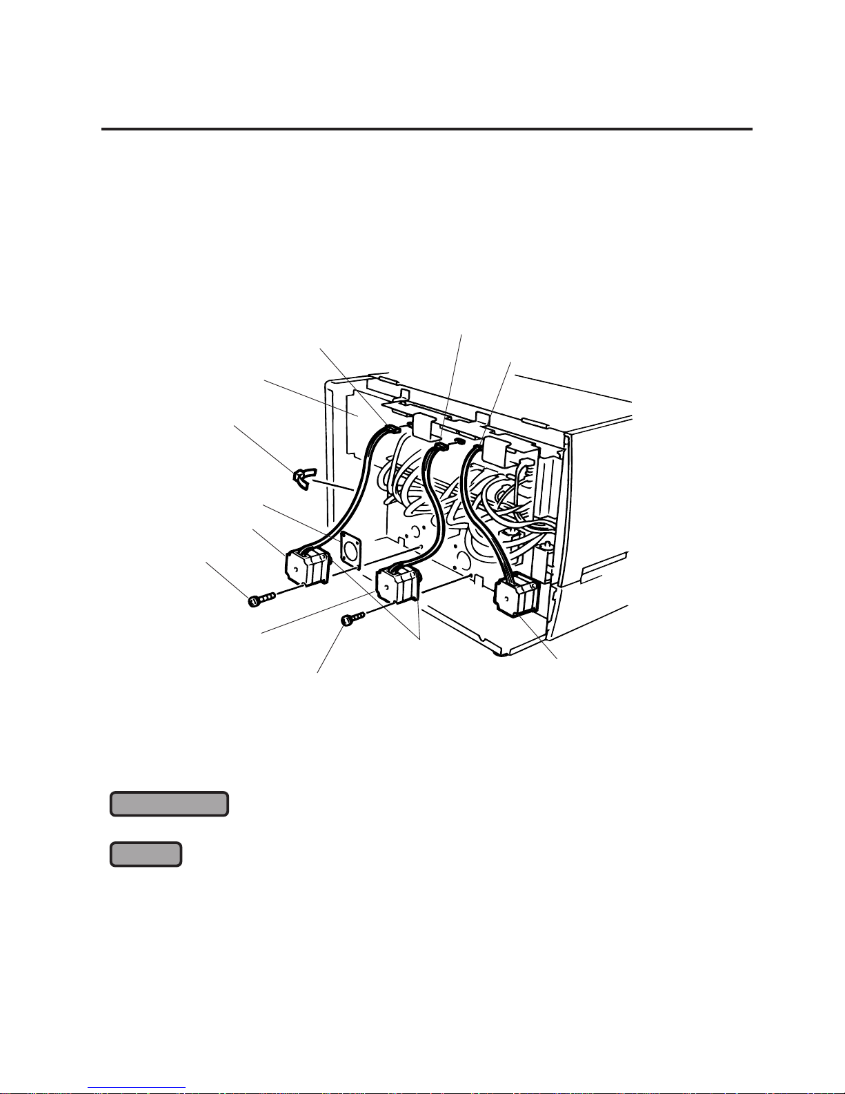
2.7 REPLACING THE PLATEN MOTOR AND FEED MOTOR
1) Remove the PS unit. (See Section 2.6.)
2) Disconnect the three cables from CN13, CN25 and CN27 on the driver PC board, and cut the cable
band binding the feed motor cable.
3) Remove the eight SM-4x8 screws to detach the two platen motors.
4) Remove the four SM-4x10 screws securing the feed motor to detach the feed roller and the motor
spacer.
5) After replacing the platen and feed motors with new ones, refer to the following [LUBRICATION] and
[CHECK] and reassemble in the reverse order of removal.
Apply FLOIL G-488 to the surface of the gears.
1. To allow sufficient backlash for the platen motor and feed motor, secure them while holding them up
slightly.
2. Refer to Fig. 2-11 to connect the harnesses correctly. Be sure to secure the feed motor cable in
position with a cable band.
2.7 REPLACING THE PLATEN MOTOR AND FEED MOTOR
CHECK
LUBRICATION
Fig. 2-11
Connector (CN25)
Connector (CN27)
Connector (CN13)
Platen Motor
(Y,C Block)
FLOIL G-488
SM-4x8 Screw
Platen Motor
(M,K Block)
SM-4x10 Screw
Feed Motor
Motor Spacer
Cable Band
Driver PC Board
Page 14

2-10
2. MAIN UNIT REPLACEMENT
EO18-33002A
2.8 REPLACING THE RIBBON MOTOR ASS’Y
1) Remove the driver PC board. (See Section 2.3.)
2) Cut the cable band binding the ribbon motor ass’y and remove the four SMW-4x8 screws to detach
the ribbon motor ass’y.
3) After replacing the ribbon motor ass’y with a new one, refer to the following [CHECK] and
[ADJUSTMENT] and reassemble in the reverse order of removal.
Install a new ribbon motor ass’y so that the ribbon flange is centered with the hole on the main frame.
Be sure to allow sufficient space for backlash when reinstalling the individual motor.
2.8 REPLACING THE RIBBON MOTOR ASS'Y
CHECK
ADJUSTMENT
Fig. 2-12
Ribbon Motor Ass'y
Hole
Ribbon Flange
Main Frame
Print Head Mechanism
SMW-4x8 Screw
Connector
Cable Band
SMW-4x8 Screw
Page 15

2-11
2. MAIN UNIT REPLACEMENT
EO18-33002A
2.9 REPLACING THE SOLENOID ASS’Y
1) Remove the PS unit. (See Section 2.6.)
2) Disconnect the solenoid ass’y cables from CN39 (yellow), CN31 (cyan), CN23 (magenta), and CN17
(black) on the driver PC board. Cut the cable band which binds the solenoid ass’y cable.
3) Remove the three SMW-3x6 screws to detach the solenoid ass’y.
4) After replacing the solenoid ass’y with a new one, refer to the following [CHECK] and [ADJUSTMENT]
and reassemble in the reverse order of removal.
Be sure to fix the solenoid ass'y cable in position with a cable band.
Solenoid installation method
Install the ribbon modules with no ribbon loaded.
Stack 6 pieces of I-BEST S paper (about 1-mm thick in total), insert them between the platen
and the print head and turn the head lock lever to the LOCK position.
Secure the solenoid ass’y so the solenoid pin softly touches the arm.
2.9 REPLACING THE SOLENOID ASS'Y
CHECK
Fig. 2-13
Connector
Arm
Pin
Solenoid Ass'y
Solenoid Ass'y
SMW-3x6 Screw
Cable Band
ADJUSTMENT
Page 16

2-12
2. MAIN UNIT REPLACEMENT
EO18-33002A
2.10REPLACING THE PRINT HEAD
4) After replacing the print head, refer to the following [CHECK] and [ADJUSTMENT] and reassemble
in the reverse order of removal.
1. After replacing the print head, turn the head lock lever to check that the print head is positioned
correctly.
2. Be sure to perform RAM clear to reset the run distance of the former print head.
If a print position misalignment (color misalignment) occurs after replacing the print head, refer to Section
5.3.3 X/Y Direction Fine Adjustment Mode to adjust the print position.
2.10 REPLACING THE PRINT HEAD
CHECK
ADJUSTMENT
Head Lock Lever
Connector
Red Screws
(Never remove them.)
Print Head
Print Head Falculum Shaft
Print Head Fixing Plate
Print Head Mechanism
Fig. 2-14
CAUTION:
1. NEVER touch the element when handling the print head.
2. NEVER touch the connector pins. Touching them may cause a static electric discharge which
will damage the print head.
3. NEVER remove the red screws. Doing so will change the adjustment.
NOTE: The print head can be replaced without removing the left side cover or the operation panel.
1) Turn the head lock lever to the LOCK position and lift the print head mechanism.
2) Lift the print head fixing plate to separate the print head from the print head mechanism.
3) Disconnect the two connectors and remove the print head from the printer.
WARNING!
Be careful when handling the print head as it becomes very hot!.
Page 17

2-13
2. MAIN UNIT REPLACEMENT
EO18-33002A
2.11REPLACING THE PLATEN AND MEDIA SENSOR
CAUTION:
NEVER remove the red screws. Doing so will change the adjustment.
1) Lift all the print head mechanism and turn the media sensor positioning knob so that the detection
point of the media sensor is positioned at the center.
2) Remove the two B-4x6 screws to detach the front cover.
3) Turn the pinch roller lever to the RELEASE position to open the pinch roller unit.
4) Remove the SMW-3x20 screw to detach the pinch roller lever.
5) Remove the four guide plates.
6) Loosen the three SMW-3x10 screws securing the under guide plate, remove the eight SMW-3x10,
nine SMW-4x8 and one SMW-3x6 screws to detach the under guide plate and the platen frame.
7) Remove the washer and two platen holders to detach the platen.
8) Disconnect the cable from CN10 on the driver PC board, cut the cable band binding the media sensor
cable, remove the knob and detach the media sensor.
2.11 REPLACING THE PLATEN AND MEDIA SENSOR
Fig. 2-15
Fig. 2-16
Pinch Roller Ass'y
Knob
SMW-3x20 Screw
Pinch Roller Lever
Nylon Washer
B-4x6 Screw
Front Cover
Guide Plate
Print Head Mechanism
Connector (CN10)
Driver PC Board
Cable Band
Knob
SMW-3x6 Screw
SMW-4x8 Screw
SMW-3x10 Screw
SMW-4x8 Screw
SMW-3x10 Screw
SMW-4x8 Screw
Platen Frame
Red Screw
(Never remove it)
Platen
FLOIL G-488
Platen Holder
SMW-3x10 Screw
Washer
Under Guide Plate
Media Sensor
Page 18

2-14
2. MAIN UNIT REPLACEMENT
EO18-33002A
9) After replacing the platen or media sensor, refer to the following [CHECK] and [ADJUSTMENT]
and reassemble in the reverse order of removal.
1. The media sensor moves smoothly by turning the knob.
2. The pinch roller lever must lock and release the pinch roller unit smoothly.
1. Determine that there is a 0.15-mm to 0.5-mm clearance between the under guide plate and the
platen using a clearance gauge.
2. Refer to Adjusting the Media Sensor Voltage on page 2-5 to readjust the voltage.
NOTE: The guide plate which differs in shape from other guide plates is to be installed nearest to the
front of the printer.
2.12REPLACING THE PINCH ROLLER ASS’Y
1) Remove the platen frame. (See Section 2.11.)
2) Remove the SMW-3x6 screw to detach the pinch roller ass’y.
3) After replacing the pinch roller ass’y, refer to the following [CHECK] and reassemble in the reverse
order of removal.
Check that the pinch roller unit is opened/closed smoothly.
2.12 REPLACING THE PINCH ROLLER ASS'Y
CHECK
ADJUSTMENT
CHECK
Pinch Roller Ass'y
SMW-3x6 Screw
Fig. 2-17
Page 19

2-15
2. MAIN UNIT REPLACEMENT
EO18-33002A
2.13DIP SWITCH SETTINGS
■ DIP SW 1
DIP switch 1 is positioned at the lower left of the driver PC board.
NOTES: 1. Be sure to set the all switches of DIP SW 1 to OFF.
2. “OFF” means “OPEN”.
2.13 DIP SWITCH SETTINGS
Fig. 2-18
■ DIP SW 2
DIP switch 2 is located on the media sensor adjsuter.
Fig. 2-19
Sems Screw SMW-3x6
Media Sensor Adjuster
VR Blind Cover
DIP SW2
Page 20

2-16
2. MAIN UNIT REPLACEMENT
EO18-33002A
2.13 DIP SWITCH SETTINGS
NOTE:The shaded settings are the factory default settings. "OFF" means "OPEN".
No.
1
2
3
4
5
6
7
8
ON/OFF
OFF
ON
OFF
ON
OFF
ON
Without
With
Without
With
Must be set to OFF.
No. detection of ribbon near end.
Pause when the ribbon near end is detected.
The ribbon near end status is sent to the PC.
Continues printing when the ribbon near end is
detected.
The ribbon near end status is not sent to the PC.
Continues printing when the ribbon near end is
detected.
The ribbon near end status is sent to the PC.
English
German
French
Dutch
Spanish
Japanese
Not used
Not used
Function
Cutter Module
6
OFF
ON
OFF
ON
OFF
ON
OFF
ON
7
OFF
OFF
ON
ON
OFF
OFF
ON
ON
8
OFF
OFF
OFF
OFF
ON
ON
ON
ON
4
OFF
ON
OFF
ON
5
OFF
OFF
ON
ON
Language to display
LCD error message
Stacker Module
Ribbon Near End
Page 21
3-1
3. INSTALLATION PROCEDURE FOR OPTIONAL EQUIPMENT
EO18-33002A
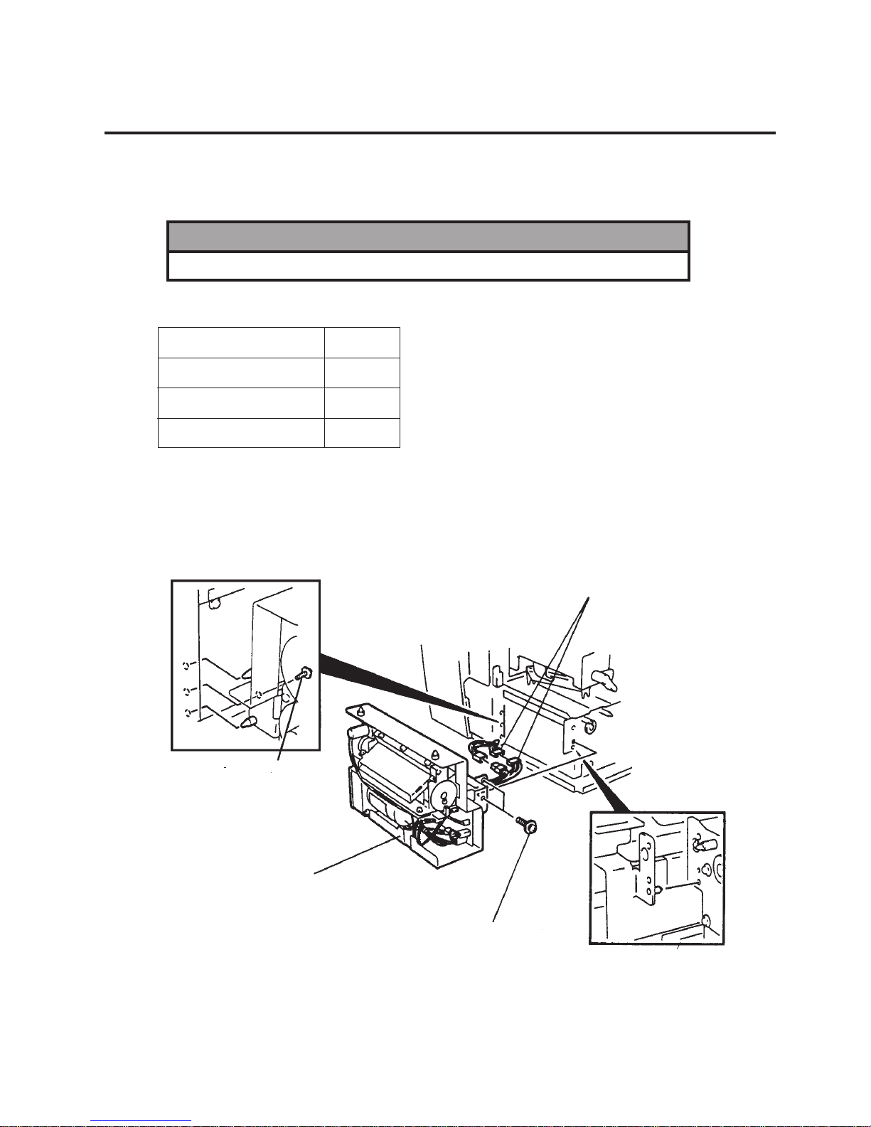
3.1 CUTTER MODULE (CB-1204-QM)
3. INSTALLATION PROCEDURE FOR OPTIONAL
EQUIPMENT
3.1 CUTTER MODULE (CB-1204-QM)
Description Q’ty/Unit
Cutter Unit 1
Cutter Cover 1
Screw (SMW-4x8) 3
1) Open the top cover and remove the two B-4x6 screws to detach the front cover. (Refer to page 2-
1.)
2) Connect the two connectors.
3) Install the cutter unit in front of the printer with the three SMW-4x8 screws.
WARNING!
Be sure to unplug the power cord before installing any optional equipment.
Fig. 3-1
SMW-4x8 Screw
SMW-4x8 Screw
Cutter Unit
Connector
Page 22

3-2
3. INSTALLATION PROCEDURE FOR OPTIONAL EQUIPMENT
EO18-33002A
3.1 CUTTER MODULE (CB-1204-QM)
4) Attach the cutter cover to the cutter unit with the two screws.
5) Closet the top cover.
6) Remove the VR blind cover from the rear of the printer and set the DIP switch 2-2 to ON.
7) When the cut position needs to be fine adjusted, refer to section 5.3.1.2.
■ Adjust Cut Angle
When the cutter cuts media obliquely, follow the procedure below to adjust the cut angle.
1) Loosen the two SMW-4x8 screws.
2) Move the guide plate back or forth so that the cutter is perpendicular to the media. Tighten the same
SMW-4x8 screws.
3) Put the ribbon onto the ribbon shaft so that the notch of the ribbon core aligns with the protrusion on
the ribbon shaft.
Fig. 3-2
Fig. 3-3
Cutter Cover
Screw
Cutter Unit
SMW-4x8 Screw
Guide Plate
SMW-4x8 Screw
Page 23

3-3
3. INSTALLATION PROCEDURE FOR OPTIONAL EQUIPMENT
EO18-33002A
3.2 RIBBON MODULE (CB-1004-QM)
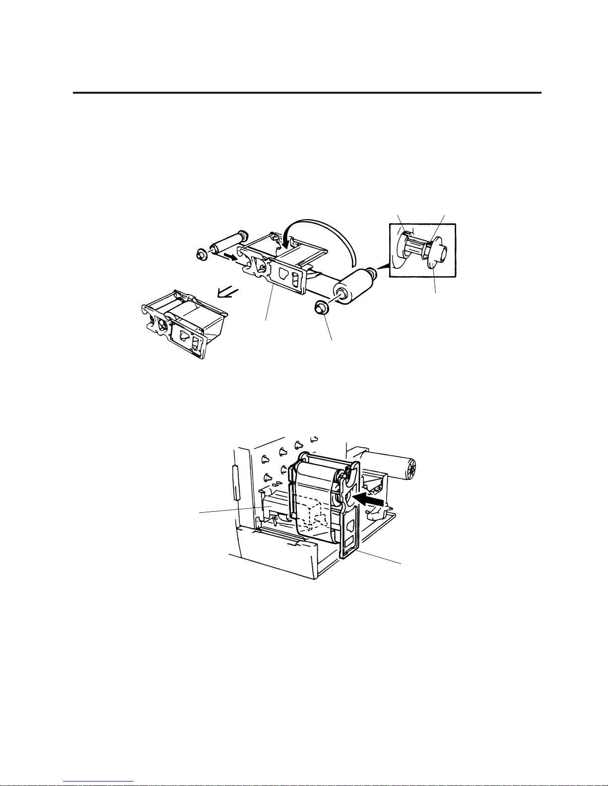
1) Remove the ribbon stopper from the ribbon shaft.
2) When the CB-1904-RK-QM Super Premium Ribbon Kit is installed in the printer, attach the enclosed
ribbon tension sheet and the sheet fixing plate using the following procedure.
NOTE: Do not attach the ribbon tension sheet to the ribbon module when the CB-1904-RK-QM is not
installed.
Remove the ribbon guide lever from the ribbon module.
Fit the bosses on the sheet fixing plate into the holes of the ribbon tension sheet and the aluminum
frame. Secure them with the three D-3x5 screws.
The double-sided adhesive tape does not need to be used.
NOTE: Do not reassemble the ribbon guide lever, ribbon guide lever shaft and D-3x6 screw because
they are unused after the ribbon tension guide sheet has been installed.
3.2 RIBBON MODULE (CB-1004-QM)
Description
Ribbon Module
Ribbon Tension Sheet
Sheet Fixing Plate
D-3x5 Screw
Q'ty/Unit
Fig. 3.4
Ribbon Cassette
Aluminum Frame
Ribbon Guide Lever
Ribbon Guide
Lever Shaft
Sheet Fixing Plate
Double-sided
Adhesive Tape
Ribbon Tension Sheet
D-3x5
D-3x6
Boss
A
1
1
1
3
A
Fig. 3.5
B
B
Page 24
3-4
3. INSTALLATION PROCEDURE FOR OPTIONAL EQUIPMENT
EO18-33002A
NOTE: Care must be taken when handling the ribbon.
6) Take up any slack in the ribbon and insert the ribbon module into the print head mechanism.
NOTE: The ribbon module should be positioned in order of yellow, cyan, magenta and black as viewed
from the front of the printer.
7) Turn the head lever to the LOCK position then once again take up any ribbon slack.
8) Close the top cover.
Fig. 3-7
Fig. 3-6
Notch
Protrusion
Ribbon Shaft
Ribbon Feed Core
Ribbon Stopper
Ribbon Module
Ribbon Winding Core
Print Head Machanism
Ribbon Module
3) Insert the ribbon onto the ribbon shaft so that the notch of the ribbon core aligns with the protrusion
on the ribbon shaft.
4) Attach the ribbon stopper to the ribbon shaft.
5) Unroll about 30 cm of the ribbon then place the ribbon module on the ribbon. Set the ribbon feed
core first then the ribbon winding core on the ribbon module in place.
3.2 RIBBON MODULE (CB-1004-QM)
Page 25

3-5
3. INSTALLATION PROCEDURE FOR OPTIONAL EQUIPMENT
EO18-33002A
3.3 PRINT HEAD FAN
3.3 PRINT HEAD FAN
When printing a high print rate pattern in batch mode, the print head will overheat, causing the print head
protection circuit to be activated. This will stop printing with displaying the error message “EXCESS
HEAD TEMP”. (e.g. When the printer prints an entire black pattern at a speed of 6"/sec., it may stop
printing after about a 6-minute operation.)
1) Unplug the power cord.
2) Remove the side panel (L) from the printer.
3) Attach the print head fan to the print head frame with the enclosed two SM-3x12 screws.
4) Connect the print head fan to the head fan harness and fix it with the cable clip.
NOTE: The harnesses and cable clips should be installed so they do not obstruct removal and
installation of the ribbon modules.
5) Install the side panel (L) to the printer.
Fig. 3-8
Cable Clip 3
SM-3x12 Screw
Head Fan Harness 2
Print Head Fan
Page 26
4-1
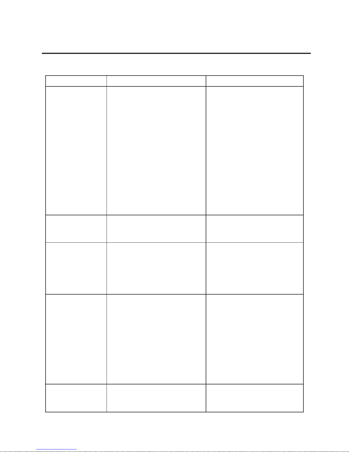
4. TROUBLESHOOTING
EO18-33002A
Cause
1.Input voltage to the printer is not
within the rated voltage.
(Check by CN1 on the PS unit.)
2.Output voltage from the printer is
not within the rated voltage.
(Check that the voltage between
Pin 5 and Pin 8 (GND) of CN2 on
the PS unit is 24V.
And check that the voltage between
Pin 1 and Pin 3 (GND) is 5V.
3.No voltage to the driver PC board.
(Check that the voltage between
Pin 5 and Pin 8 (GND) of CN44 on
the CPU PC board is 24V. And
check that the voltage between Pin
1 and Pin 8 (GND) is 5V.)
4.Failure of the driver PC board.
1.Failure of the LED board/LCD
2.Failure of the LCD/LED harness
3.Failure of the driver PC board
1.The print paper is of poor quality.
2.Dirty print head
3. The head lever fastens the print
head incompletely.
4.Failure of the driver PC board.
1.Print head failure
2.Connection of the print head
connector is incomplete, a bad
contact, or broken wires.
3.Failure in rewinding/feeding of the
ribbon.
4.Failure of the driver PC board
5.Failure of the CPU PC board.
6.Failure of the software
7.Failure of the printer cable
1.Broken print head element
2.Broken print head cable wires
3.Failure of the driver PC board
4. TROUBLESHOOTING
4. TROUBLESHOOTING
Problems
Power does not turn
ON.
LED or LCD does not
light.
Poor printing
Printer does not print.
Dot missing
Solution
• Replace the power cable or power
inlet.
• Replace the PS unit.
• Replace the power harness.
• Replace the driver PC board.
• Replace the LED board/LCD.
• Replace the LCD/LED harness.
• Replace the driver PC board.
• Use the media approved by
TOSHIBA TEC.
• Clean the print head.
• Fasten the head lever completely.
• Replace the driver PC board.
• Replace the print head.
• Connect the harness completely,
or replace the harness.
• Replace the ribbon rewind motor,
ribbon feed motor or driver PC
board.
• Replace the driver PC board.
• Replace the CPU PC board.
• Check the program.
• Replace the printer cable.
• Replace the print head.
• Replace the print head harness.
• Replace the driver PC board.
Page 27

4-2
4. TROUBLESHOOTING
EO18-33002A
4. TROUBLESHOOTING
Solution
• Use only TOSHIBA TEC specified
media.
• Clean the print head and remove
any dust from the media.
• Re-load the ribbon properly.
• Use only TOSHIBA TEC specified
ribbon.
• Replace the ribbon rewind motor
or ribbon feed motor.
• Use only TOSHIBA TEC specified
ribbon.
• Set the paper properly.
• Use paper approved by TOSHIBA
TEC.
•
Adjust the media sensor sensitivity
and voltage.
• Replace the feed gap sensor or
black mark sensor.
• Replace the feed motor, platen
motor or driver PC board.
• Install the cutter mechanism
properly.
• Refer to Section 5.3.3 to adjust
the print position.
• Replace the cable.
• Modify the program.
• Replace the IC57, 42, 27, 1, 18,
38
If the trouble is not solved, replace
the CPU PC board.
• Replace the driver PC board.
Problems
Blurred print
Ribbon wrinkle
Ribbon end error
Label feed failure
Print position
misalignment
Communication error
Cause
1.Poor media quality.
2.Dust is on the media.
1.Improper ribbon loading
2.Poor ribbon quality
3.Ribbon is not rewound or fed
smoothly.
Poor ribbon quality
1.Paper is not set properly.
2.Paper of poor quality
3. Improper adjustment of the feed
gap sensor or black mark sensor.
4. The proper media sensor is not
selected.
5.Failure of the feed gap sensor or
black mark sensor
6.Failure of the feed motor or platen
motor.
7.The cutter mechanism is not
installed properly.
Print position has not been adjusted.
1.Failure of the printer cable
2. Failure of the PC or application
software
3.Failure of the CPU PC board
4.Driver PC board failure.
Page 28

TABLE OF CONTENTS
5. DIAG. TEST OPERATION.......................................................................5- 1
5.1 OUTLINE OF THE DIAG. TEST OPERATION..................................5-1
5.2 SELF TEST MODE............................................................................5-2
5.2.1 Automatic Diagnostic Printing.................................................5-2
5.2.2 Maintenance Counter Printing ................................................5-7
5.3 PARAMETER SETTING MODE......................................................5-10
5.3.1 Position Adjustment Mode ....................................................5-12
5.3.1.1 Print start position fine adjustment .........................5-12
5.3.1.2 Cut position fine adjustment...................................5-13
5.3.1.3 Reverse feed distance fine adjustment..................5-14
5.3.1.4 Print stop position fine adjustment .........................5-17
5.3.1.5 X-coordinate fine adjustment .................................5-18
5.3.2 Print tone Fine Adjustment Mode .........................................5-20
5.3.3 X and Y-directions Fine Adjustment Mode ...........................5-21
5.3.3.1 Setting conditions for adjustment value
confirmation print....................................................5-21
5.3.3.2 Status print before X/Y-directions adjustment.......5-22
5.3.3.3 X-direction fine adjustment.....................................5-24
5.3.3.4 Y-direction fine adjustment.....................................5-27
5.3.3.5 Adjustment value confirmation print.......................5-30
5.3.4 Print Start Position Fine Adjustment Mode...........................5-32
5.3.5 Printer Parameter Setting Mode ...........................................5-33
5.3.5.1 Character code selection .......................................5-33
5.3.5.2 Font zero selection.................................................5-34
5.3.5.3 Control code selection............................................5-35
5.3.5.4 Pulse motor speed selection ..................................5-36
5.3.5.5 Euro Font Code Selection......................................5-37
5.3.6 Platen Speed Fine Adjustment Mode ...................................5-38
5.3.7 Color Designation Mode .......................................................5-39
5.3.8 Ribbon Type Selection Mode ...............................................5-40
5.3.9 Supply Holder's Paper End Sensor Selection ......................5-41
5.3.10 Resolution Selection.............................................................5-42
5.4 TEST PRINT MODE........................................................................5-43
5.4.1 Normal Test Print..................................................................5-43
5.4.2 Process Test Print ................................................................5-49
5.5 RAM CLEAR MODE........................................................................5-51
5.5.1 Maintenance Counter Clear..................................................5-53
5.5.2 Parameter Clear ...................................................................5-54
5.5.3 Print Step Clear ....................................................................5-55
EO18-33002
(Revision Date: Dec. 20, 2000)
Page
CAUTION:
1. This manual may not be copied in whole or in part without prior written permission of TOSHIBA
TEC.
2. The contents of this manual may be changed without notification.
3. Please refer to your local Authorized Service representative with regard to any queries you may
have in this manual.
Page 29
5-1
EO18-33002A
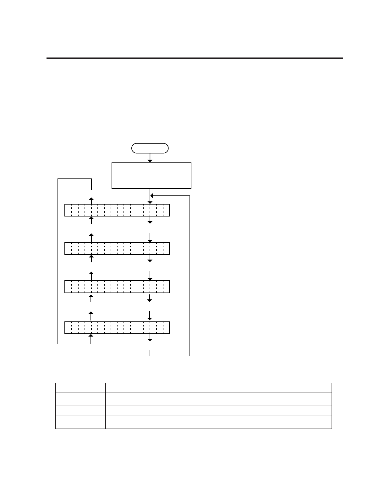
5. DIAG. TEST OPERATION
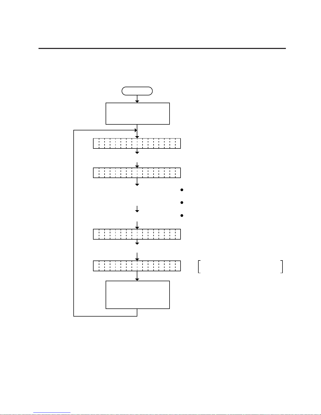
Power off
Press the [RESTART] key.
Press the [RESTART] key. Press the [FEED] key.
Turn on the power while
holding down the [FEED]
key and [PAUSE] key.
<1 DIAG. V1.OA>
Press the [RESTART] key. Press the [FEED] key.
Press the [FEED] key.
<2 PARAMETER S ET>
<3 TEST PRINT>
<4 RAM CLEAR>
Press the [RESTART] key. Press the [FEED] key.
emaNyeKnoitcnuF
]DEEF[yek
asaedommetsysehttratsotdesU]ESUAP[ enifotroedomretemarapehtdetcelesotdesU.seodyek
.)-(noitceridevitagenehtnisretemarapehttsujda
]TRATSER[yek
.)+(noitceridevitisopehtnisretemarapehttsujdaenifotroedomretemarapehttcelesotdesU
]ESUAP[yek
asaedommetsysehttratsotdesU]DEEF[ nasadesU.edomretemarapehttcelesotdnaseodyek
.yekretne
In system mode the [FEED], [RESTART] and [PAUSE] keys function as described below.
■ Key Function Table
(Revision Date: Dec. 20, 2000)
5.1 OUTLINE OF THE DIAG. TEST OPERATION
5. DIAG. TEST OPERATION
5.1 OUTLINE OF THE DIAG. TEST OPERATION
In system mode the diag. test operation is used to diagnose the printer and to set the parameters by using
the [FEED], [RESTART] and [PAUSE] keys on the operation panel. Diag. test operation
is started from the power off state. For further details, please refer to the corresponding pages.
NOTE: Every size in this manual is written in millimeter. To obtain the size in inch, divide by 25.4.
■ Type 1
■ Self Test Mode (See page 5-2)
Data from the maintenance counter and
automatic diagnosis are printed on the
media.
■ Parameter Setting Mode (See page 5-10)
Fine adjustment of the feed length, cut position,
reverse feed distance, X-coordinate, print tone,
print stop position, X and Y-directions alignment,
print start position and selection of character
font, font zero, control code, supply Holders
paper end sensor, resolution and Euro Font
Code are available in this mode.
■ Test Print Mode (See page 5-42)
Print condition and test print type (slant line,
characters and bar code) are selectable.
■ RAM Clear Mode (See page 5-51)
Data from the maintenance counter is cleared
and parameter setting is initialized in the RAM
clear mode.
Page 30
5-2
EO18-33002A
5. DIAG. TEST OPERATION
NOTES: 1. If the automatic diagnosis printing results in an error, the printer will display the
error message and stop printing. The error status can be cleared by the [PAUSE]
key, however, the display will return to the initial display “<1> DIAG. V1.0A”.
Printing is not automatically resumed.
2. Both label and tag paper can be used for printing.
5.2 SELF TEST MODE
5.2 SELF TEST MODE
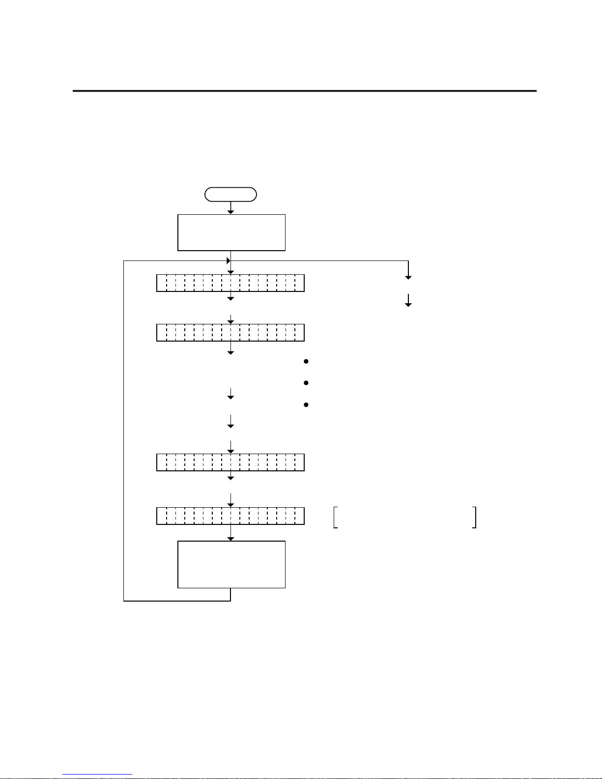
In self test mode the printer status is printed in two types of sample print.
5.2.1 Automatic Diagnostic Printing
The data from 1 to 9 on a sample print is printed.
Power off
Press the [PAUSE] key.
Press the [PAUSE] key.
Press the [PAUSE] key.
Select the sensor type from those
at the right by pressing the
[FEED] key or [RESTART] key.
Press the [PAUSE] key.
Continued on Section 5.2.2
Maintenance counter printing.
Turn on the power while
holding down the [FEED]
key and [PAUSE] key.
Press the [FEED] key.
The result of the self test
is printed. After printing,
the initial display will be
shown.
TRANSMISSIVE
REFLECTIVE
(black mark sensor)
NONE
(consecutive form)
(feed gap sensor)
The printer is checking or printing
the status
<1 DIAG. V1.OA>
SE SOR TRANS.N
AU O DIAGNOSTICT
CH CKING & PRINTE
Page 31

5-3
EO18-33002A
5. DIAG. TEST OPERATION
(Revision Date: Dec. 20, 2000)
5.2 SELF TEST MODE
PROGRAM (BOOT) V1.0 A FMRM0048401
Checksum
Firmware No. of ROM of software
Revision No.: Space or A to Z
Software version No.
Firmware Name
PROGRAM (BOOT): Boot Area
PROGRAM (PROGRAM): Program Area
MASK: Mask ROM (Character generator)
C500:
BITMAP
KANJI ROM2 Checksum
KANJI ROM1 Checksum
0000 0000
:
NOTES: 1. Checksum varies according to the software version.
2. When the KANJI ROM is not installed or the top 1 byte of KANJI ROM is improper
data, the checksum becomes “0000”.
3. The last two digits of the checksum are not 0.
Fig. 5-1
■ Sample Print
[Print Condition]
• Preset count : 1
• Print speed : 6” mm/sec.
• Sensor :No sensor
• Printing method : Thermal transfer
• Supply length : 102 mm
• Issuing mode : Batch printing
NOTES: 1. Software version No., firmware No., and checksum very according to the software
version of PROGRAM/MASK ROM.
2. The last two digits of the checksum are usually 0.
(2) KANJI ROM Check
(1) PROGRAM/MASK ROM Check
(1)
(2)
(3)
(4)
(5)
(6)
(7)
(8)
(9)
(10)
(11)
(12)
(13)
(14)
(15)
(16)
VERSION PARTS NO. CHECK SUM
PROGRAM (BOOT) : V1.0 7200
PROGRAM (PROGRAM) : V1.0 FMRM0048401 C500
MASK : 6D44
KANJI ROM CHECK CHECK SUM
BITMAP : 28BA:7446
EEPROM BACKUP CHECK : OK
SIMM CHECK : OK
MEMORY (SIMM) :16MB (SLOT1:16MB, SLOT2:0MB)
OPEN-AIR TEMPERATURE SENSOR : AB
PSU TEMPERATURE SENSOR : 80
HEAD 1HEAD2
BLACK MAGENTACYAN YELLOW
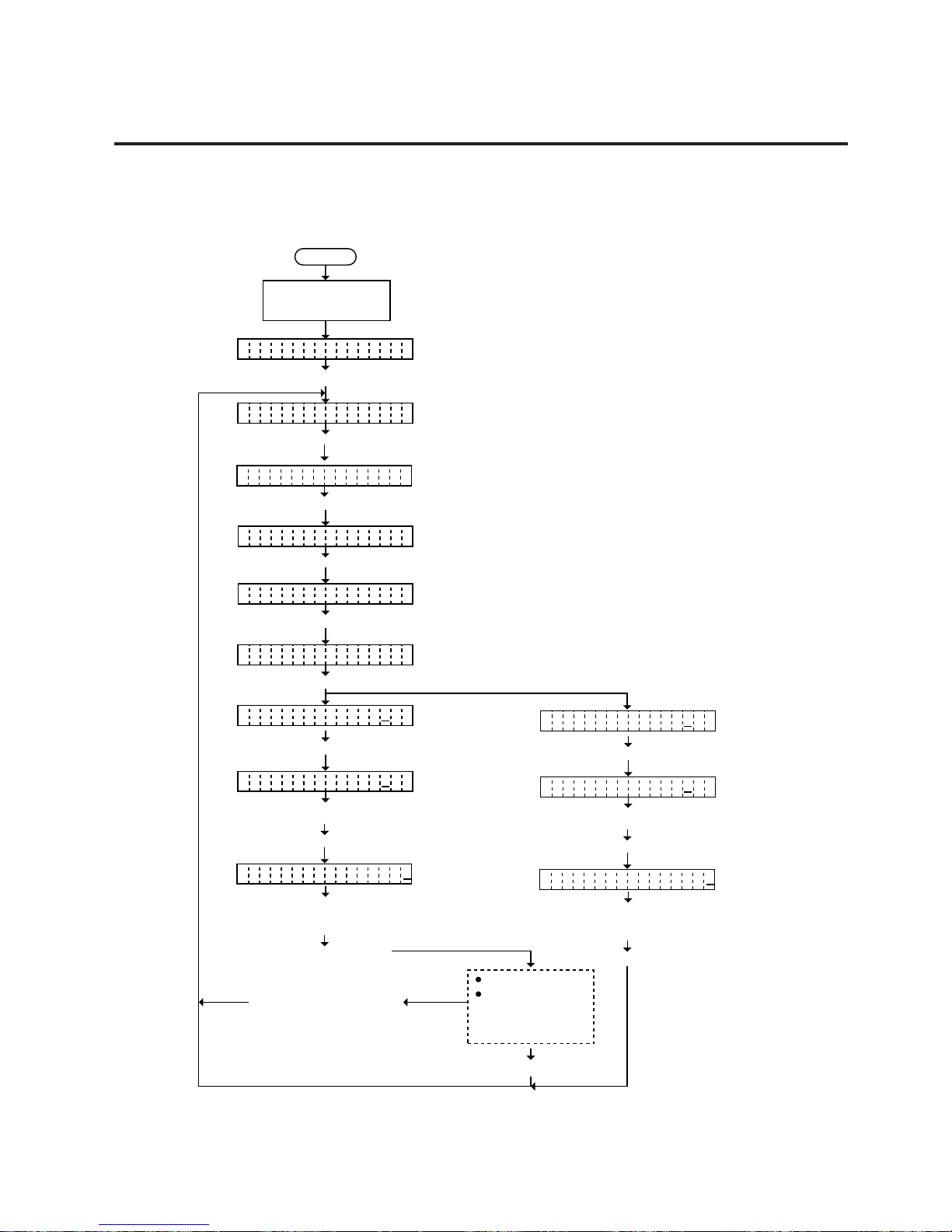
HEAD TEMPERATURE SENSOR : A3 A3 A3 A5
HEAD RESISTANCE RANK : 06 0A 09 04
REFLECTIVE SENSOR : 0 (0;WHITE, 1:BLACK MARK)
TRANSMISSIVE SENSOR : 0 (0;LABEL, 1:GAP)
PEEL OFF SENSOR : 0 (0;NOT EXIST, 1:EXIST)
PAPER END SENSOR : 0 (0:PAPER EXIST, 1:END)
CUTTER SENSOR : 0 (0:OUT OF POSITION, 1:IN THE POSITION)
HEAD 1HEAD2
RIBBON MOTER ENCODER BLACK MAGENTACYAN YELLOW
REWIND A : 1 0 1 0
REWIND B : 0 0 0 0
SUPPLY A : 0 1 0 0
SUPPLY B : 1 1 1 0
(0:IN SLIT, 1:OUT OF SLIT)
DIP SW :11011010,00100000 (0:OFF, 1:ON)
: The CB-426-T3 does not print these data.
CB-426
CB-416
CB-426
CB-416
Page 32
5-4
EO18-33002A
5. DIAG. TEST OPERATION
(Revision Date: Apr. 20, ’99)
5.2 SELF TEST MODE
EEPROM BACK UP OK
EEPROM: Backup memory
Read/write check
OK: Data in the check area can be properly
read/written.
NG: Data in the check area cannot be
properly read/written.
SIMM CHECK OK
OK: Data in the memory is readable/writable.
NG: Some data in the memory is not readable/writable
SIMM: Image buffer memory or work memory
MEMORY (SIMM) 16MB (SLOT1: 16MB, SLOT2: 0MB)
Total memory
SIMM capacity on SLOT2
SIMM capacity on SLOT1
Image buffer memory or work memory
(5) SIMM Memory Capacity Check
(3) EEPROM Backup Check
(4) SIMM Check
NOTE: If an error is detected during SIMM check, the display of readable/writable area will stop
when the error occurs.
OPEN-AIR TEMPERATURE SENSOR : B2
Environmental temperature (A/D value)
(6) Environmental temperature check
PSU TEMPERATURE SENSOR : 7F
PSU temperature (A/D value)
Thermal sensor 2
(7) PSU temperature check
Page 33
5-5
EO18-33002A
5. DIAG. TEST OPERATION
5.2 SELF TEST MODE
HEAD TEMPERATURE SENSOR : AD AF AF B1
Temperature of yellow print head (A/D value)
Temperature of black print head (A/D value)
Temperature of magenta print head (A/D value)
Temperature of cyan print head (A/D value)
(8) Print head temperature check
HEAD RESISTANCE RANK : 0C 06 0C 0D
Resistance rank of yellow print head (A/D value)
Resistance rank of black print head (A/D value)
Resistance rank of magenta print head (A/D value)
Resistance rank of cyan print head (A/D value)
(9) Print head resistance rank
REFLECTIVE SENSOR : 0 (0: WHITE, 1: BLACK MARK)
Reflective sensor
0: Print area
1: Black mark
(10) Reflective sensor check
(11) Transmissive sensor check
TRANSMISSIVE SENSOR : 0 (0: LABEL, 1: GAP)
Transmissive sensor
0: Print area
1: Inter-label gap
(12) Strip sensor check
PEEL OFF SENSOR : 0 (0: NOT EXIST, 1: EXIST)
Strip sensor
0: No paper
1: Presence of paper
Page 34

5-6
EO18-33002A
5. DIAG. TEST OPERATION
5.2 SELF TEST MODE
(14) Cutter home position sensor
(13) Paper end sensor
PAPER END SENSOR : 0 (0:PAPER EXIST, 1: END)
Paper end sensor
0: Presence of paper
1: Paper end
CUTTER SENSOR : 0 (0: OUT OF POSITION, 1: IN THE POSITION)
Cutter sensor
0: Out of home position
1: Home position
(15) Slit sensor check
CB-416
RIBBON MOTOR ENCODER
REWIND A :
REWIND B :
SUPPLY A :
SUPPLY B :
BLACK
1
0
0
1
MAGENTA
0
0
1
1
Slit sensor
0: At the slit
1: Out of the slit
CYAN
1
0
0
1
YELLOW
0
0
0
0
(16) DIP switch check
No. : 8 7 6 5 4 3 2 1 8 7 6 5 4 3 2 1
DIP Switch 2 (on VR PCB)
0 0 0 0 1 0 0 0 , 0 0 0 1 1 0 1 1
DIP Switch 1 (on Driver PCB)
0: OFF
1: ON
CB-426
RIBBON MOTOR ENCODER
REWIND A :
REWIND B :
SUPPLY A :
SUPPLY B :
HEAD1
1
0
0
0
HEAD2
0
0
1
0
Slit sensor
0: At the slit
1: Out of the slit
Page 35
5-7
EO18-33002A
5. DIAG. TEST OPERATION
NOTES: 1. If the maintenance counter printing results in an error, the printer will display the
error message and stop printing. The error status can be cleared by the [PAUSE]
key, however, the display will return to the initial display “<1> DIAG. V1.0A”.
Printing is not automatically resumed after the error is cleared.
2. Both label and tag paper can be used for printing.
5.2.2 Maintenance Counter Printing
The data from 1 to I on a sample print is printed. This data is the printer status and the
value set in the parameter setting mode.
5.2 SELF TEST MODE
Power off
Press the [PAUSE] key.
Press the [PAUSE] key.
Press the [PAUSE] key.
Select the sensor type from those
at the right by pressing the
[FEED] key or [RESTART] key.
Turn on the power while
holding down the [FEED]
key and [PAUSE] key.
The result of the self test
is printed. After printing,
the initial display will be
shown.
TRANSMISSIVE
REFLECTIVE
(black mark sensor)
NONE
(consecutive form)
(feed gap sensor)
The printer is checking or printing
the status
<1 DIAG. V1.OA>
SE SOR TRANS.N
MA NTENANCE CONTI
CH CKING & PRINTE
Page 36
5-8
EO18-33002A
5. DIAG. TEST OPERATION
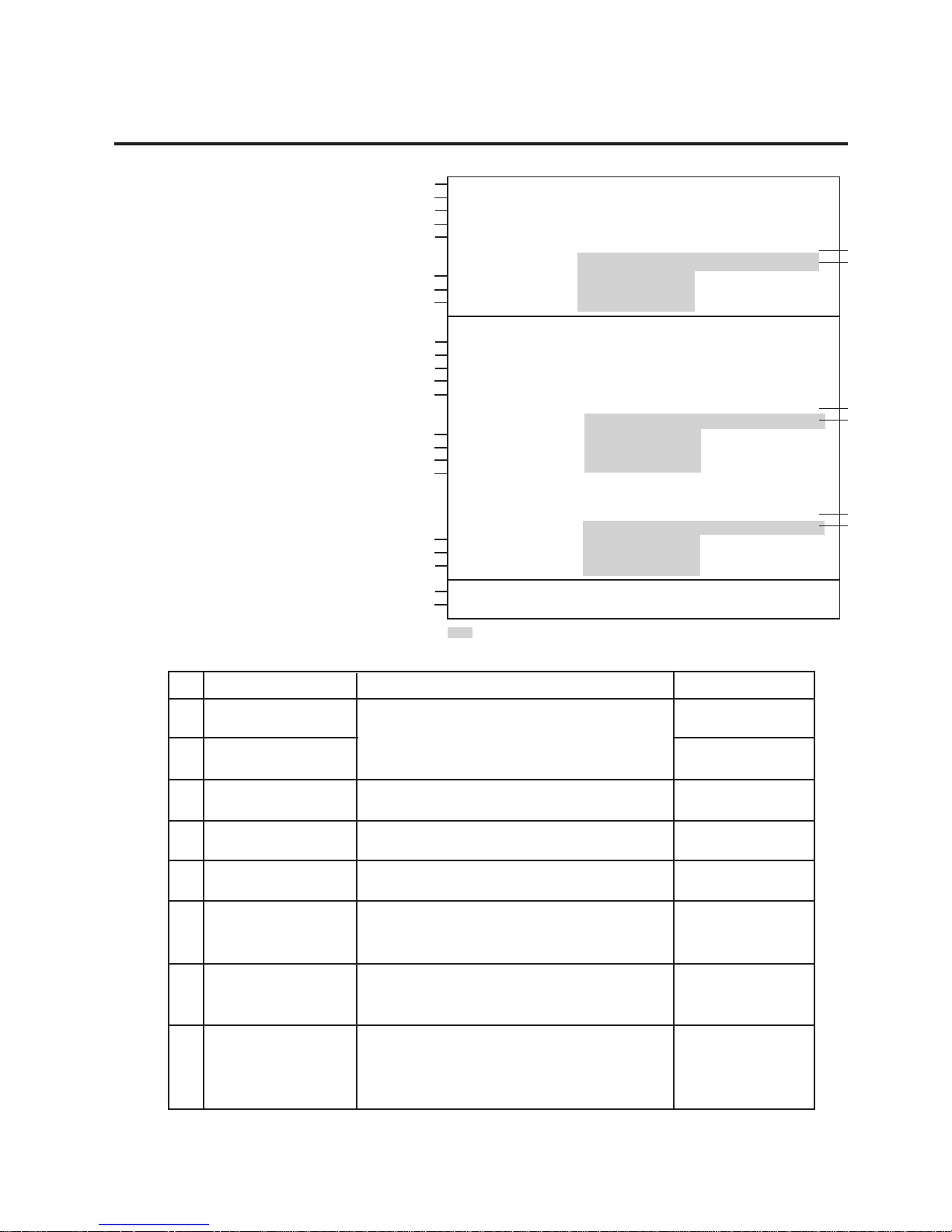
Fig. 5-2
5.2 SELF TEST MODE
■ Sample Print
[Print Condition]
• Preset count : 1
• Print speed : 6”/sec.
• Sensor :No sensor
• Printing method : Thermal transfer
• Supply length : 126 mm
• Issuing mode : Batch printing
1) Maintenance Counter
#
(1)
(2)
(3)
(4)
(5)
(6)
(7)
(8)
Item
Total media distance
covered
Media distance
covered
Cut count
RS-232C hardware
error count
Momentary power
failure count
Print distance
Head up and down
count
Ribbon motor driving
time
Count Condition
Counted when the feed motor drives to feed,
print and issue the media. (Counted also
during ribbon save operation and back feed.)
[See NOTE 2.]
Counts every cut. [See NOTE 3.]
Counted when a parity, overrun or framing
error occurs. [See NOTE 5.]
Counts the number of times the power restores
while the CPU is busy after reset.
Counted while printing. (Feeding and issuing
media, and ribbon saving operation are not
counted.) [See NOTE 2.]
Counts every up and down of the print head
using the solenoid for ribbon save operation.
(Up + Down = 2 count) [See NOTE 3.]
Counts when the ribbon motor drives to feed,
print and issue the media. (The driving time is
not count during ribbon saving operation, but is
during back feed.) [See NOTE 4.]
Range
0.0 to 3200.0 km
0.0 to 200.0 km
0.0 to 1000000
times
0 to 255 times
0 to 15 times
0.0 to 200.0 km
0 to 2000000 times
0 to 2000 hours
(1)
(2)
(3)
(4)
(5)
(6)
(7)
(8)
(9)
(10)
(11)
(12)
(13)
(14)
(15)
(16)
(17)
(14)
(15)
(16)
(18)
(19)
TL FEED : 0.0Km
FEED : 0.0Km
CUT : 0
232C ERR : 0
PW FALL : 0
HEAD 1 HEAD2
BLACK MAGENTA CYAN YELLOW
PRINT : 0.0 Km 0.0Km 0.0Km 0.0Km
HEAD U/D : 192 64 96 64
RIBBON : 0h 0h 0h 0h
[PC] [KEY]
FEED : +0.0mm -2.0mm
CUT : +0.0mm +0.0mm
BACK : +0.0mm +0.0mm
STOP : +0.0MM +0.0MM
X ADJ. : --- +0.0mm
[PC] HEAD 1 HEAD2
BLACK MAGENTA CYAN YELLOW
X DIRECTION : +0.00mm +0.00mm +0.00mm +0.00mm
Y DIRECTION : +0.00mm +0.00mm +0.00mm +0.00mm
TONE : +0step +0step +0step +0step
RIBBON VOLTAGE
REWIND : +0step +0step +0step +0step
SUPPLY : +0step +0step +0step +0step
[KEY] HEAD 1 HEAD2
BLACK MAGENTA CYAN YELLOW
X DIRECTION : +0.00mm +0.00mm +0.00mm +0.00mm
Y DIRECTION : +0.00mm -0.08mm -0.42mm -0.50mm
TONE : +0step +0step +0step +0step
FONT : [PC-850] [0]
CODE : [AUTO]
: The CB-426-T3 does not print these data.
CB-426
CB-416
CB-426
CB-416
CB-426
CB-416
Page 37
5-9
EO18-33002A
5. DIAG. TEST OPERATION
(Revision Date: Dec. 20, 2000)
5.2 SELF TEST MODE
2) Parameters
#
(9)
(10)
(11)
(12)
(13)
(14)
(15)
(16)
(17)
(18)
(19)
Item
FEED [KEY]
FEED [PC]
CUT [PC, KEY]
BACK [KEY]
BACK [PC]
STOP [PC, KEY]
X ADJ.
X DIRECTION
Y DIRECTION
TONE
FONT
CODE
Description
Print start position fine adjustment
Print start position fine adjustment
Cut position fine adjustment
Reverse feed distance fine adjustment
Reverse feed distance fine adjustment
Print stop position fine adjustment
X-coordinate fine adjustment
X-direction fine adjustment
CB-416: Black/Magenta/Cyan/Yellow
CB-426: HEAD1/HEAD2
Y-direction fine adjustment
CB-416: Black/Magenta/Cyan/Yellow
CB-426: HEAD1/HEAD2
Print tone fine adjustment
CB-416: Black/Magenta/Cyan/Yellow
CB-426: HEAD1/HEAD2
Ribbon take-up motor voltage fine adjustment
CB-416: Black/Magenta/Cyan/Yellow
CB-426: HEAD1/HEAD2
Ribbon feed motor voltage fine adjustment
CB-416: Black/Magenta/Cyan/Yellow
CB-426: HEAD1/HEAD2
Character code selection
Font zero selection
Control code selection
Remarks
-30.0 mm ~ +13.0 mm
-30.0 mm ~ +10.0 mm
-20.0 mm ~ +20.0 mm
-9.5 mm ~ +9.5 mm
-9.9 ~ +9.9 mm
-30.0 ~ +300.0 mm
-99.5 mm ~ +99.5 mm
-2.00 mm ~ +2.00 mm
-2.00 mm ~ +2.00 mm
-50 ~ +50 step
-50 ~ +50 setp
-50 ~ +50 setp
PC-850 : PC-850
PC-8: PC-8
0: No slash used.
0: Slash used.
AUTO:
Automatic selection
ESC LF NUL:
ESC LF NUL mode
{ | } : { | } mode
REWIND
SUPPLY
RIBBON
VOLTAGE
NOTES: 1. Item from (2) through (16) are initialized to “0” after RAM clear.
2. If the distance is 5.5 m or less, it is rounded down and no data is added to the
memory at power off.
3. If the count is 31 counts or less, it is rounded down and no data is added to the
memory at power off.
4. If the driving time is 36 sec. or less, it is rounded down and no data is added to the
memory at power off.
5. When a sent command results in an error, the same number as the data capacity
of the command is counted by byte.
Page 38

5-10
EO18-33002A
5. DIAG. TEST OPERATION
(Revision Date: Dec. 20, 2000)
5.3 PARAMETER SETTING MODE
5.3 PARAMETER SETTING MODE
The following 12 items are set in the parameter setting mode. The values set in this mode are printed
on the sample print of the maintenance counter. Setting procedure and functions are provided below.
Power off
Press the [FEED] key.
Turn on the power while
holding down the [FEED]
key and [PAUSE] key.
<1 DIAG. V1.OA>
Press the [FEED] key.
PO ITIONS
PR NT CONDITIONI
Press the [FEED] key.
PR NT DENSITYI
Press the [FEED] key.
HE D ADJUSTA
Press the [FEED] key.
PR NTER PARAI
Press the [FEED] key.
Press the [FEED] key.
AD USTJ
Press the [FEED] key.
X- IRECTI OND
Press the [FEED] key.
Y- IRECTI OND
Press the [FEED] key.
CH CKE
Press the [FEED] key.
PM ADJUST
Press the [FEED] key.
HE D SELECTA
Press the [FEED] key.
RI BONB
<2 PARAME TER S ET>
Press the [PAUSE] key.
Press the [PAUSE] key.
Press the [FEED] key.
SU PL Y HOLDE RP
Press the [FEED] key.
RE OLUTIO N S
Press the [FEED] key.
HE D ADJUST3A
Page 39

5-11
EO18-33002A
5. DIAG. TEST OPERATION
■ Parameter Setting Mode Table
(Revision Date: Dec. 20, 2000)
5.3 PARAMETER SETTING MODE
Mode Name
POSITION
PRINT DENSITY
HEAD ADJUST
HEAD ADJUST3
SUPPLY HOLDER
RESOLUTION
PRINTER PARA
PM ADJUST
HEAD SELECT
RIBBON
Function
<Position adjustment mode>
Fine adjustment of the print start position, cut position, reverse feed
distance, print stop position, and X-coordinate
<Print tone fine adjustment mode>
Print tone fine adjustment of each print head
<X and Y-directions fine adjustment mode>
Fine adjustment of each color’s alignment
• PRINT CONDITION: print condition setting
• ADJUST: Status print before X/Y-directions adjustment
• X DIRECTION: X-direction alignment fine adjustment
• Y DIRECTION: Y-direction alignment fine adjustment
• CHECK: Adjustment value confirmation print
<Print start position fine adjustment mode>
Print start position fine adjustment of each print head for page 1 to page
10
<Supply holder’s paper end sensor selection>
Selection of the use of the supply holder’s paper end sensor
<Resolution selection>
Selection of the resolution
<Printer parameter setting mode>
Selection of the character code, font zero, control code, Euro Code
and pulse motor speed
<Platen speed fine adjustment mode>
Fine adjustment of the platen speed
<Color designation mode>
Selection of used or unused print head
<Ribbon type selection>
Setting the ribbon type for each print head
Page 40

5-12
EO18-33002A
5. DIAG. TEST OPERATION
Power off
Press the [FEED] key.
Turn on the power while
holding down the [FEED]
key and [PAUSE] key.
[FEED] key: pressing the [FEED] key one
time is a -0.5 mm change, up to
-30.0 mm. (See NOTE 2.)
<1 DIAG. V1.OA>
<2 PARA METER SET>
[RESTART] key:pressing the [RESTART] key
one time is a +0.5 mm change,
up to +13.0 mm.
(See NOTE 2.)
Press the [PAUSE] key.
Press the [PAUSE] key.
Press the [PAUSE] key.
PO ITIONS
FE D ADJ. +0.0mmE
Press the [FEED] or
[RESTART] key to adjust
the feed length.
(See NOTE 1.)
Press the [FEED] key
and [RESTART] key
at the same time.
Continued on Section 5.3.1.2
Cut Position Fine Adjustment.
Print start position fine adjustment
Position adjustment mode display
(Revision Date: Apr. 20, ’99)
5.3 PARAMETER SETTING MODE
5.3.1 Position Adjustment Mode
5.3.1.1 Print Start Position Fine Adjustment
NOTES: 1. Holding the [FEED] key or [RESTART] key down for more than 0.5 seconds
enables a fast forward.
2. Max. fine adjustment +13.0 mm, -30.0 mm = Key fine adjustment value + PC fine
adjustment value.
When the value reaches the maximum, the value remains unchanged even if the
subsequent fine adjustment is performed.
3. A change feed value is stored in memory by pressing the [PAUSE] key.
Page 41

5-13
EO18-33002A
5. DIAG. TEST OPERATION
Power off
Press the [FEED] key.
Turn on the power while
holding down the [FEED]
key and [PAUSE] key.
[FEED] key: pressing the [FEED] key one
time is a -0.5 mm change, up to
-20.0 mm. (See NOTE 2.)
<1 DIAG. V1.OA>
<2 PARA METER SET>
[RESTART] key:pressing the [RESTART] key
one time is a +0.5 mm change,
up to +20.0 mm.
(See NOTE 2.)
Press the [PAUSE] key.
Press the [PAUSE] key.
Press the [PAUSE] key twice.
PO ITIONS
CU ADJ. +0.0mmT
Press the [FEED] or
[RESTART] key to adjust
the feed length.
(See NOTE 1.)
Press the [FEED] key
and [RESTART] key
at the same time.
Continued on Section 5.3.1.3
Reverse Feed Distance Fine Adjustment.
Cut position fine adjustment
Position adjustment mode display
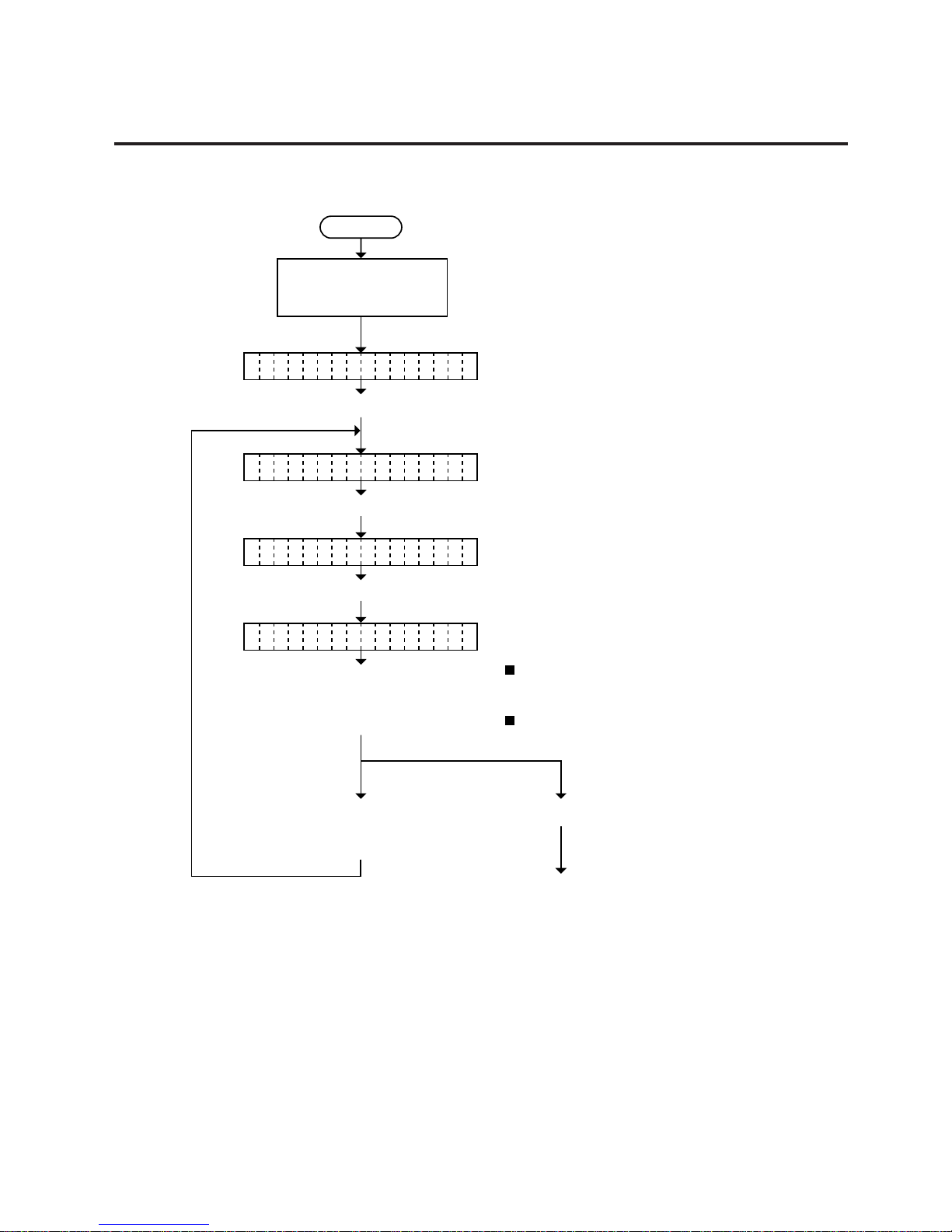
NOTES: 1. Holding the [FEED] key or [RESTART] key down for more than 0.5 seconds
enables a fast forward.
2. Max. fine adjustment
±
20.0 mm = Key fine adjustment value + PC fine adjustment
value.
When the value reaches the maximum, the value remains unchanged even if a
subsequent fine adjustment is performed.
3. A changed cut/strip position value is stored in memory by pressing the [PAUSE]
key.
5.3 PARAMETER SETTING MODE
5.3.1.2 Cut Position Fine Adjustment
Page 42
5-14
EO18-33002A
5. DIAG. TEST OPERATION
Power off
Press the [FEED] key.
Turn on the power while
holding down the [FEED]
key and [PAUSE] key.
[FEED] key: Pressing the [FEED] key one
time is a -0.5 mm change, up to
-9.5 mm. (See NOTE 2.)
<1 DIAG. V1.OA>
<2 PARA METER SET>
[RESTART] key:Pressing the [RESTART] key
one time is a +0.5 mm change,
up to +9.5 mm. (See NOTE 2.)
Press the [PAUSE] key.
Press the [PAUSE] key.
Press the [PAUSE] key three times.
PO ITIONS
BA K ADJ. +0.0mmC
Press the [FEED] or
[RESTART] key to adjust
the feed length.
(See NOTE 1.)
Press the [FEED] key
and [RESTART] key
at the same time.
Continued on Section 5.3.1.4
Print Stop Position Fine Adjustment.
Reverse feed distance fine adjustment
Position adjustment mode display
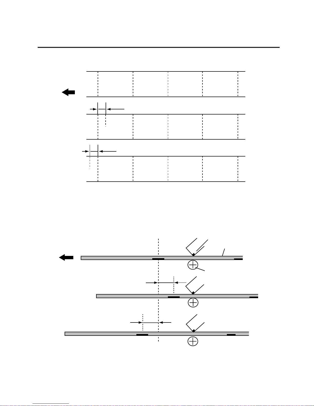
NOTES: 1. Holding the [FEED] key or [RESTART] key down for more than 0.5 seconds
enables a fast forward.
2. Max. fine adjustment
±
9.5 mm = Key fine adjustment value + PC fine adjustment
value.
When the value reaches the maximum, the value remains unchanged even if the
subsequent fine adjustment is performed.
3. A changed back feed value is stored in memory by pressing the [PAUSE] key.
5.3 PARAMETER SETTING MODE
5.3.1.3 Reverse Feed Distance Fine Adjustment
Page 43
5-15
EO18-33002A
5. DIAG. TEST OPERATION
A
A
A
A
A
A
A
A
A
A
A
A
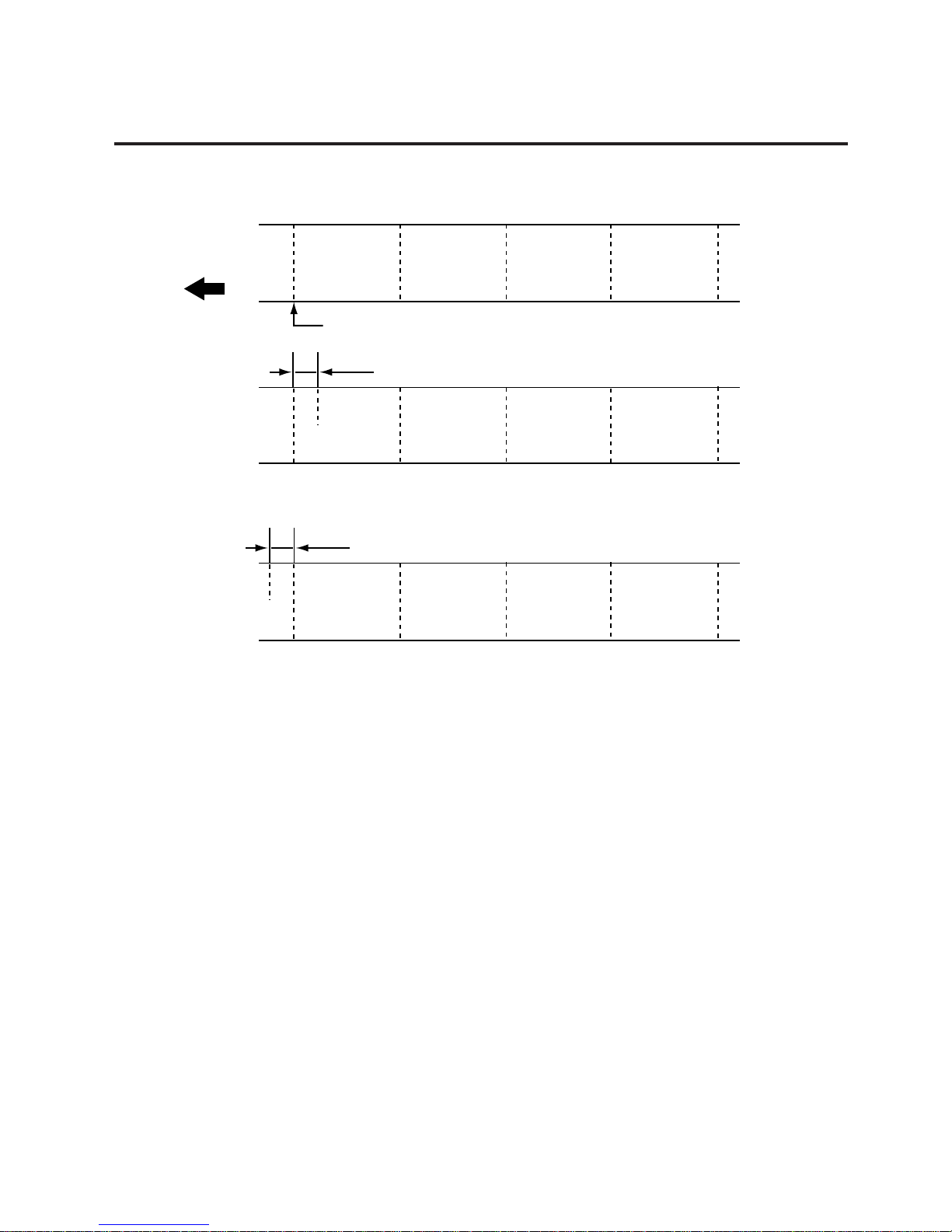
+ 0.0 mm
Feed Direction
- 10.0 mm
+ 10.0 mm
+ 10 mm
- 10 mm
Fig. 5-3
Fig. 5-4
Fig. 5-5
+ 0.0 mm
Feed Direction
- 12.0 mm
+ 12.0 mm
Black Mark
Cut Position
Print Head
Tag Paper
Platen
- 12 mm
- 12 mm
Fig. 5-6
Fig. 5-7
Fig. 5-8
5.3 PARAMETER SETTING MODE
■ Print start position fine adjustment example
■ Cut position fine adjustment example
Page 44
5-16
EO18-33002A
5. DIAG. TEST OPERATION
5.3 PARAMETER SETTING MODE
A
A
A
A
A
A
A
A
A
A
A
A
+ 0.0 mm
Feed Direction
+3.0 mm
-3.0 mm
-3.0 mm
+3.0 mm
Print start position
Fig. 5-9
Fig. 5-10
Fig. 5-11
■ Reverse feed distance fine adjustment example
Page 45

5-17
EO18-33002A
5. DIAG. TEST OPERATION
Power off
Press the [FEED] key.
Turn on the power while
holding down the [FEED]
key and [PAUSE] key.
[FEED] key: pressing the [FEED] key one
time is a -0.5 mm change, up to
-30.0 mm. (See NOTE 2.)
<1 DIAG. V1.OA>
<2 PARA METER SET>
[RESTART] key:pressing the [RESTART] key
one time is a +0.5 mm change,
up to +300.0 mm.
(See NOTE 2.)
Press the [PAUSE] key.
Press the [PAUSE] key.
Press the [PAUSE] key four times.
PO ITIONS
ST P ADJ. +0.0mmO
Press the [FEED] or
[RESTART] key to adjust
the Print stop psition.
(See NOTE 1.)
Press the [FEED] key
and [RESTART] key
at the same time.
Continued on Section 5.3.1.5
X-Coordinate Fine Adjustment.
Print stop position fine adjustment
Position adjustment mode display
NOTES: 1. Holding the [FEED] key or [RESTART] key down for more than 0.5 seconds
enables a fast forward.
2. Max. fine adjustment - 30.0 mm, + 300.0 mm = Key fine adjustment value + PC fine
adjustment value.
When the value reaches the maximum, the value remains unchanged even if the
subsequent fine adjustment is performed.
3. A changed feed value is stored in memory by pressing the [PAUSE] key.
5.3 PARAMETER SETTING MODE
5.3.1.4 Print Stop Position Fine Adjustment
Page 46
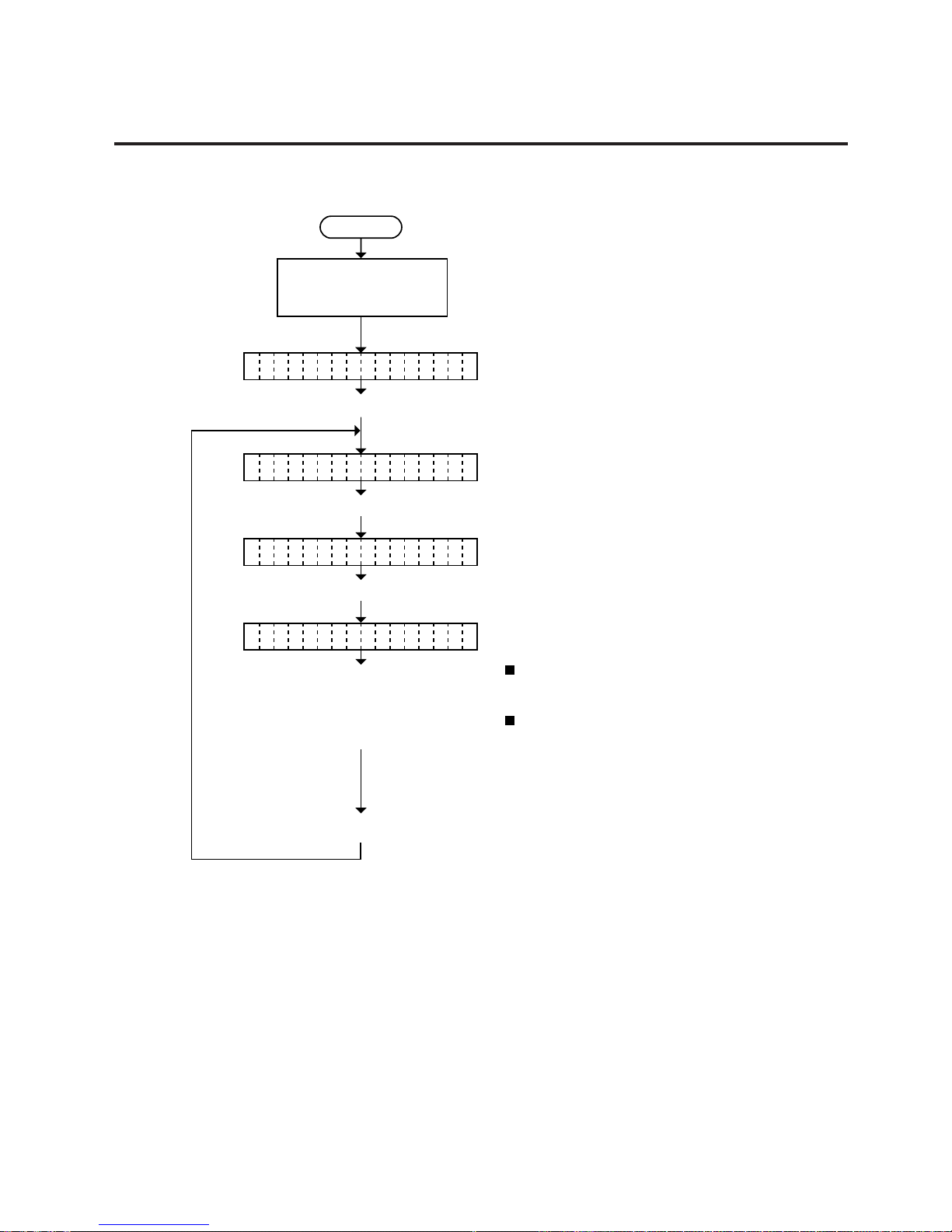
5-18
EO18-33002A
5. DIAG. TEST OPERATION
Power off
Press the [FEED] key.
Turn on the power while
holding down the [FEED]
key and [PAUSE] key.
[FEED] key: Pressing the [FEED] key one
time is a -0.5 mm change, up to
-99.5 mm. (See NOTE 2.)
<1 DIAG. V1.OA>
<2 PARA METER SET>
[RESTART] key:Pressing the [RESTART] key
one time is a +0.5 mm change,
up to +99.5 mm.
(See NOTE 2.)
Press the [PAUSE] key.
Press the [PAUSE] key.
Press the [PAUSE] key five times.
PO ITIONS
X DJUST +0.0mmA
Press the [FEED] or
[RESTART] key to fine
adjust the print position
along the X-coordinate
(See NOTE 1.)
X-coordinate fine adjustment
Position adjustment mode display
NOTES: 1. Holding the [FEED] key or [RESTART] key down for more than 0.5 seconds
enables a fast forward.
2. Max. fine adjustment
±
99.5 mm = X-coordinate value
When the value reaches the maximum, the value remains unchanged even if the
subsequent fine adjustment is performed.
3. A changed X-coordinate is stored in memory by pressing the [PAUSE] key.
5.3 PARAMETER SETTING MODE
5.3.1.5 X-Coordinate Fine Adjustment
Page 47

5-19
EO18-33002A
5. DIAG. TEST OPERATION
5.3 PARAMETER SETTING MODE
To down printing
Bottom first printing
+0.0 mm
-50.0 mm
-50.0 mm
+50.0 mm
X
X
Y
Y
Feed direction
ABC
ABC
ABC
+ 50.0 mm
NOTES: 4. The X-coordinate fine adjustment is performed to fine adjust the X-coordinate of
the drawing in the left or right direction.
5. Adjust the X-coordinate in the effective print range. (After the value reaches the
coordinate “0”, the value remains unchanged even if the subsequent fine adjustment
is performed in the negative direction.)
6. X-coordinate fine adjustment cannot be used in self test mode or test printing.
Fig. 5-12
Fig. 5-13
Fig. 5-14
■ X-coordinate Fine Adjustment Example
Page 48
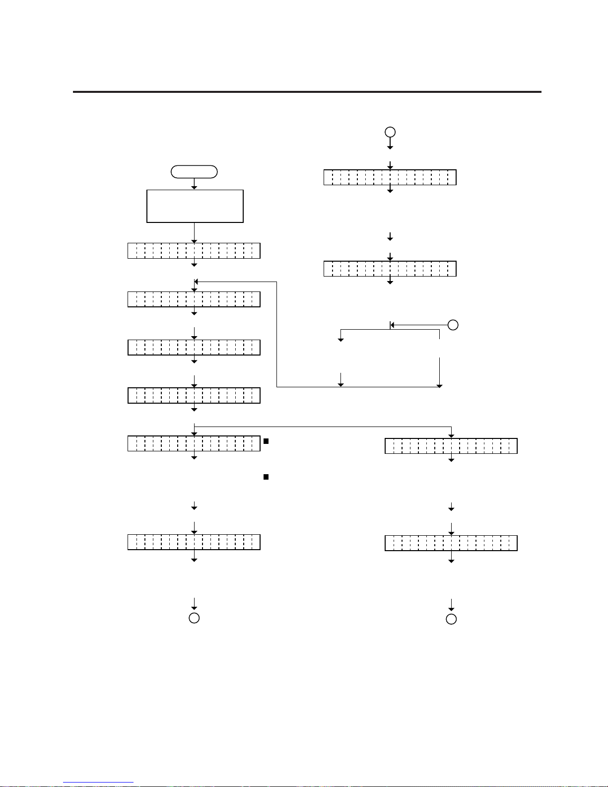
5-20
EO18-33002A
5. DIAG. TEST OPERATION
Power off
Press the [FEED] key.
Turn on the power while
holding down the [FEED]
key and [PAUSE] key.
[FEED] key:
pressing the [FEED] key one
time is a -1 step change, up to
-50 steps. (See NOTE 2.)
<1 DIAG. V1.OA>
<2 PARAMETER S ET>
[RESTART] key:
pressing the [RESTART] key
one time is a +1 step change,
up to +50 steps.
(See NOTE 2.)
Press the [PAUSE] key.
Press the [FEED] key.
PO ITIONS
Press the [PAUSE] key.
Press the [FEED] key
and [RESTART] key
at the same time.
Press the [PAUSE] key.
CY N +0A
PR NT DENSITYI
Press the [PAUSE] key.
Press the [PAUSE] key.
BL CK +0A
MA ENTA +0G
Press the [FEED] or
[RESTART] key to adjust
the print tone.
(See NOTE 1.)
Print tone fine adjustment mode
Press the [FEED] or
[RESTART] key to adjust
the print tone.
(See NOTE 1.)
Press the [PAUSE] key.
YE LOW +0L
Press the [FEED] or
[RESTART] key to adjust
the print tone.
(See NOTE 1.)
Press the [FEED] or
[RESTART] key to adjust
the print tone.
(See NOTE 1.)
A
A
B
•CB-416
HE D1 A
Press the [FEED] or
[RESTART] key to adjust
the print tone.
(See NOTE 1.)
Press the [PAUSE] key.
HE D2 A
Press the [FEED] or
[RESTART] key to adjust
the print tone.
(See NOTE 1.)
B
•CB-426
NOTES: 1 Holding the [FEED] key or [RESTART] key down for more than 0.5 seconds
enables a fast forward.
2. Max. fine adjustment
±
50 steps = print tone fine adjustment value + PC fine
adjustment value
When the value reaches the maximum, the value remains unchanged even if the
subsequent fine adjustment is performed.
3. A changed print tone value is stored in memory by pressing the [PAUSE] key.
5.3 PARAMETER SETTING MODE
5.3.2 Print Tone Fine Adjustment Mode
Page 49
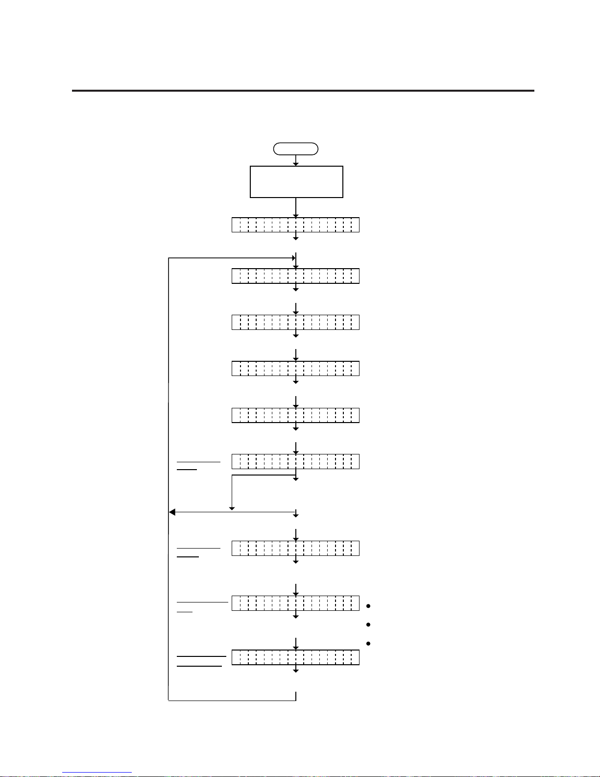
5-21
EO18-33002A
5. DIAG. TEST OPERATION
Power off
Press the [FEED] key.
Turn on the power while
holding down the [FEED]
key and [PAUSE] key.
<1 DIAG. V1.OA>
<2 PA RAMETE R SE T>
Press the [PAUSE] key.
Press [PAUSE] key.
PR NT CONDITIONI
Press [PAUSE] key.
IS UE COUNT 5S
Set the number of labels to
be printed with the
[FEED] or [PAUSE] key.
Press the [PAUSE] key.
Press the [FEED]
and [RESTART] keys
at the same time.
Set the print
count
Set the print
speed
Set the sensor
type
Set the media
back feeding
PR NT SPEED 6"/SI
Set print speed with the
[FEED] or [PAUSE] key.
SE SOR TRANS.N
Set the sensor type with the [FEED]
or [PAUSE] key.
BA K FEED YESC
Select use or non use of reverse
feed with the [FEED] or [PAUSE] key.
Press the [FEED] key twice.
PO ITIONS
HE D ADJUSTA
TRANSMISSIVE
REFLECTIVE
(black mark sensor)
NONE
(consecutive form)
(feed gap sensor)
X and Y-directions fine
adjustment display
10 (Print count 10)
6" / sec.
4" / sec.
~
~
1 (Print count 1)
Print parameter setting mode
With reverse feed
Without reverse feed
5.3 PARAMETER SETTING MODE
5.3.3 X and Y-Directions Fine Adjustment Mode
5.3.3.1 Setting Conditions for Adjustment Value Confirmation Print
Page 50

5-22
EO18-33002A
5. DIAG. TEST OPERATION
Power off
Press the [FEED] key.
Turn on the power while
holding down the [FEED]
key and [PAUSE] key.
<1 DIAG. V1.OA>
5 labels are issued
according to the print conditions set
in Section 5.3.3.1 by pressing the [PAUSE] key.
Press [FEED] key.
AD USTJ
PR NT CONDITIONI
<2 PARA METER SET>
Press the [PAUSE] key.
Press [PAUSE] key.
Press the [PAUSE] key twice.
PO ITIONS
HE D ADJUSTA
Print condition setting display
X and Y-directions fine adjustment display
5.3 PARAMETER SETTING MODE
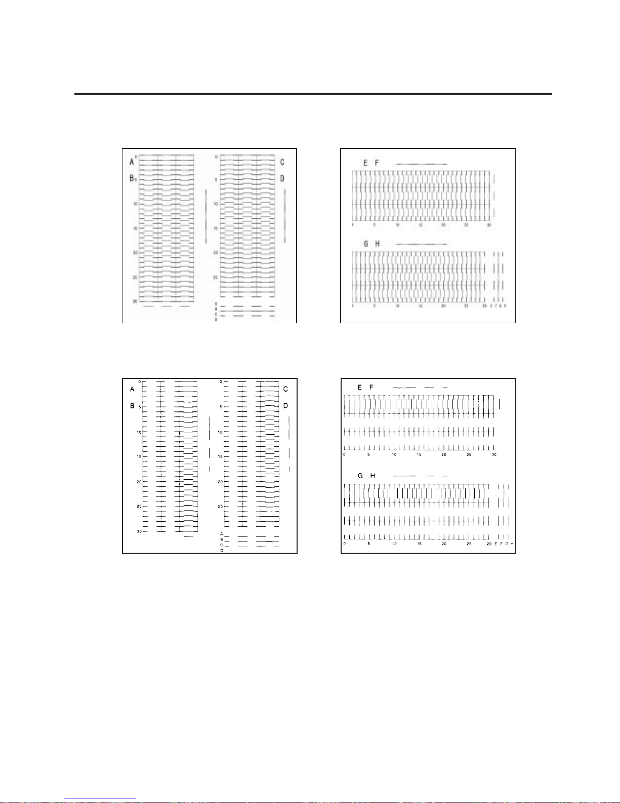
5.3.3.2 Status print before X/Y-directions adjustment
The following test patterns which show the status before X/Y-directions adjustment are printed.
Page 51
5-23
EO18-33002A
5. DIAG. TEST OPERATION
5.3 PARAMETER SETTING MODE
NOTES: 1. When an error occurs during printing, the error message is displayed and
printing is stopped. The error is cleared by pressing the [PAUSE] key and the
display shows “<2> PARAMETER SET”. Printing is not automatically resumed
after the error is cleared.
2. Extract the 3rd and 4th labels and use them for adjustment.
■ CB-416
■ CB-426
Page 52
5-24
EO18-33002A
5. DIAG. TEST OPERATION
5.3 PARAMETER SETTING MODE
5.3.3.3 X-direction fine adjustment
Check the point where a line of each color aligns with a black line on the X-direction test pattern
and enter the obtained adjustment value.
Power off
Press the [FEED] key.
Turn on the power while
holding down the [FEED]
key and [PAUSE] key.
<1 DIAG. V1.OA>
<2 P ARAME TER SET>
Press the [PAUSE] key.
Press the [FEED] key twice.
PO ITIONS
Press the [FEED] key twice.
PR NT CONDITIONI
HE D ADJUSTA
Press [PAUSE] key.
X IRECTIOND
Press [PAUSE] key.
Set the alphabet with the
[FEED] or [RESRART] key.
Press the [FEED] key and
[RESTART] key at same time.
Press the [PAUSE] key.
Press the [PAUSE] key.
BL CK F00A
X and Y-directions fine adjustment display
Print condition setting display
Skip Black's X-direction
fine adjustment
Alphabet: E, F, G, or H
Magenta's X-direction
fine adjustment value
(Alphabet)
Number: 00 to 30
X-direction fine adjustment display
MA ENTA F00G
Press the [PAUSE] key twice.
Set the number with the
[FEED] or [RESTART] key.
(See NOTE 1.)
CYAN
YELLOW
Repeat the above
procedure to other
print heads.
Magent's X-direction fine
adjustment
MA ENTA F00G
Press the [PAUSE] key.
•CB-416
Set the alphabet with the
[FEED] or [RESRART] key.
Press the [PAUSE] key.
HE D1 F00A
Skip 1st print head
X-direction fine
adjustment
Alphabet:
E, F, G, or H
2nd print head
X-direction fine
adjustment value
(Alphabet)
Number: 00 to 30
HE D2 F00A
Press the [PAUSE] key twice.
Set the number with the
[FEED] or [RESTART] key.
(See NOTE 1.)
2nd print head
X-direction fine
adjustment
HE D2 F00A
Press the [PAUSE] key.
•CB-426
NOTES: 1 When setting G or H for alphabet, the range of the number becomes 01 to 29.
2. This operation allows the max. of
±
4.00 mm change for each color adjustment.
Page 53

5-25
EO18-33002A
5. DIAG. TEST OPERATION
5.3 PARAMETER SETTING MODE
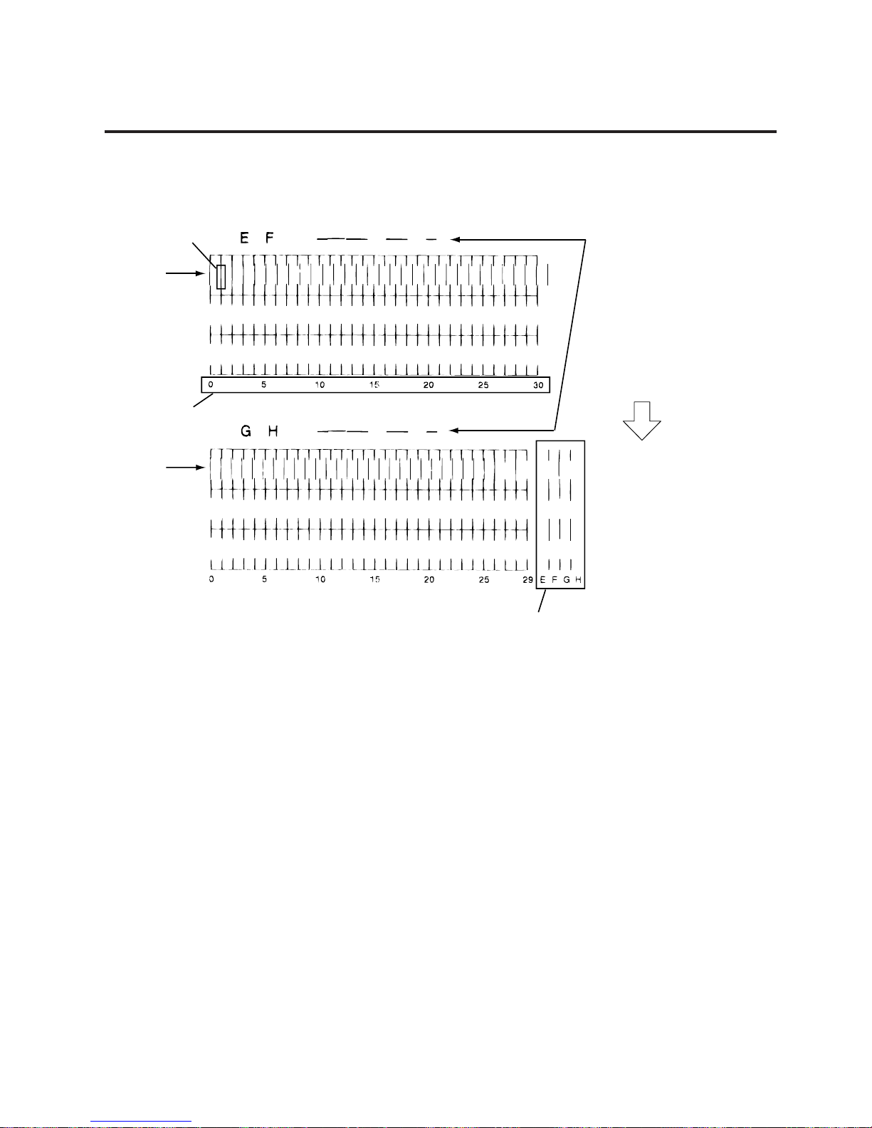
1) Check where magenta belongs among rows E~H within the portion 1.
2) In this example, magenta is printed on the row F. When magenta is printed on the row E or F,
refer to the upper print sample.
When row G or H, refer to the lower print sample.
3) Check where a magenta aligns with the black line (indicated by 2). Read the scale of the position
(indicated by 3).
4) Enter the alpha-numerics obtained in steps 1) through 3) into the Head Adjust display. In this case,
enter F7.
5) The values for cyan and yellow are obtained in the same way.
■ Adjustment example (CB-416)
X-direction fine adjustment method is explained using magenta.
Feed
X-direction misalignment
E and F : + (plus) direction
G and H: - (minus) direction
These lines indicate Y-direction
alignment.
(When they align and form an almost
straight line, the adjustment is
completed.)
Cyan
Magenta
Yellow
Cyan
Magenta
Yellow
Magenta
Page 54
5-26
EO18-33002A
5. DIAG. TEST OPERATION
5.3 PARAMETER SETTING MODE
1) Check where 2nd print head belongs among rows E~H within the portion 1.
2) In this example, 2nd print head is printed on the row F. When 2nd print head is printed on the row
E or F, refer to the upper print sample.
When row G or H, refer to the lower print sample.
3) Check where a 2nd print head aligns with the black line (indicated by 2). Read the scale of the
position (indicated by 3).
4) Enter the alpha-numerics obtained in steps 1) through 3) into the Head Adjust display. In this case,
enter F1.
■ Adjustment example (CB-426)
X-direction fine adjustment method is explained using 2nd print head.
Feed
X-direction misalignment
E and F : + (plus) direction
G and H: - (minus) direction
These lines indicate Ydirection alignment.
(When they align and form
an almost straight line, the
adjustment is completed.)
2nd Print
Head
Magenta
2nd Print
Head
3
1
2
Page 55

5-27
EO18-33002A
5. DIAG. TEST OPERATION
5.3 PARAMETER SETTING MODE
5.3.3.4 Y-Direction Fine Adjustment
Check the point where a line of each color aligns with a black line on theYX-direction test pattern
and enter the obtained adjustment value.
Power off
Press the [FEED] key.
Turn on the power while
holding down the [FEED]
key and [PAUSE] key.
<1 DIAG. V1.OA>
<2 P ARAME TER SE T>
Press the [PAUSE] key.
Press the [FEED] key twice.
PO ITIONS
Press the [FEED] key three times.
PR NT CONDITIONI
HE D ADJUSTA
Press [PAUSE] key.
Y IRECTIOND
Press [PAUSE] key.
Set the alphabet with the
[FEED] or [RESTART] key.
Press the [FEED] key and
[RESTART] key at same time.
Press the [PAUSE] key.
Press the [PAUSE] key.
BL CK B00A
X and Y-directions fine adjustment
display
Print condition setting display
Skip Black's Y-direction
fine adjustment
Alphabet: A, B, C, or D
Magenta's Y-direction
fine adjustment value
(Number)
Number: 00 to 30
Y-direction fine adjustment display
MA ENTA B00G
Press the [PAUSE] key.
Set the number with the
[FEED] or [RESTART] key.
(See NOTE 1.)
CYAN
YELLOW
Repeat the above
procedure to other
print heads.
Magenta's Y-direction
fine adjustment value
(Number)
MA ENTA B00G
Press the [PAUSE] key twice.
•CB-426
Set the Number with the
[FEED] or [RESRART] key.
See NOTE1
HE D2 B00A
2nd print head
Y-direction fine
adjustment value
(Number)
Alphabet: A, B, C,
or D
2nd print head
Y-direction fine
adjustment value
(Number)
Number: 00 to 30
HE D2 B00A
Press the [PAUSE] key.
•CB-416
Set the alphabet with the
[FEED] or [RESRART] key.
HE D1 B00A
Skip 1st print head
Y-direction fine
adjustment
Press the [PAUSE] key.
NOTES: 1 When setting C or D for alphabet, the range of the number becomes 01 to 29.
2. This operation allows the max. of
±
4.00 mm change for each color adjustment.
Page 56
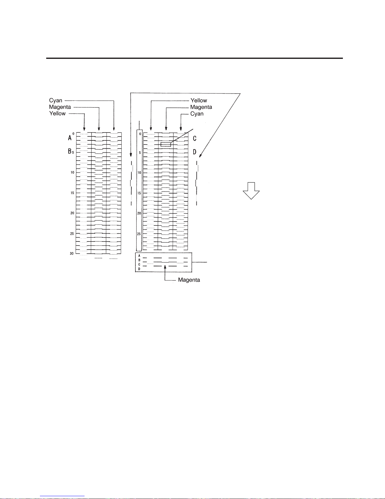
5-28
EO18-33002A
5. DIAG. TEST OPERATION
5.3 PARAMETER SETTING MODE
■ Adjustment example (CB-416)
Y-direction fine adjustment method is explained using magenta.
These lines indicate X-direction
alignment.
(When they align and form an almost
straight line, the adjustment is
completed.)
Y-direction misalignment
A and B : + (plus) direction
C and D: - (minus) direction
1) Check where magenta belongs among rows A~D within the Portion 4.
2) In this example, magenta is printed on the row C. When magenta is printed on the row A or B, refer
to the left print sample.
When row C or D, refer to the right print sample.
3) Check where a magenta aligns with the black line (indicated by 5). Read the scale of the position
(indicated by 6).
4) Enter the alpha-numerics obtained in steps 1) through 3) into the Head Adjust window. In this case,
enter C3.
5) The values for cyan and yellow are obtained in the same way.
6) After completing the adjustment and print a sample pattern for confirmation in Section 5.3.3.5
Adjustment Value Confirmation Print. If it is still misaligned, retry the adjustment so that the four
colors mostly align at the center of portions 1 and 4.
Feed
6
5
4
Page 57
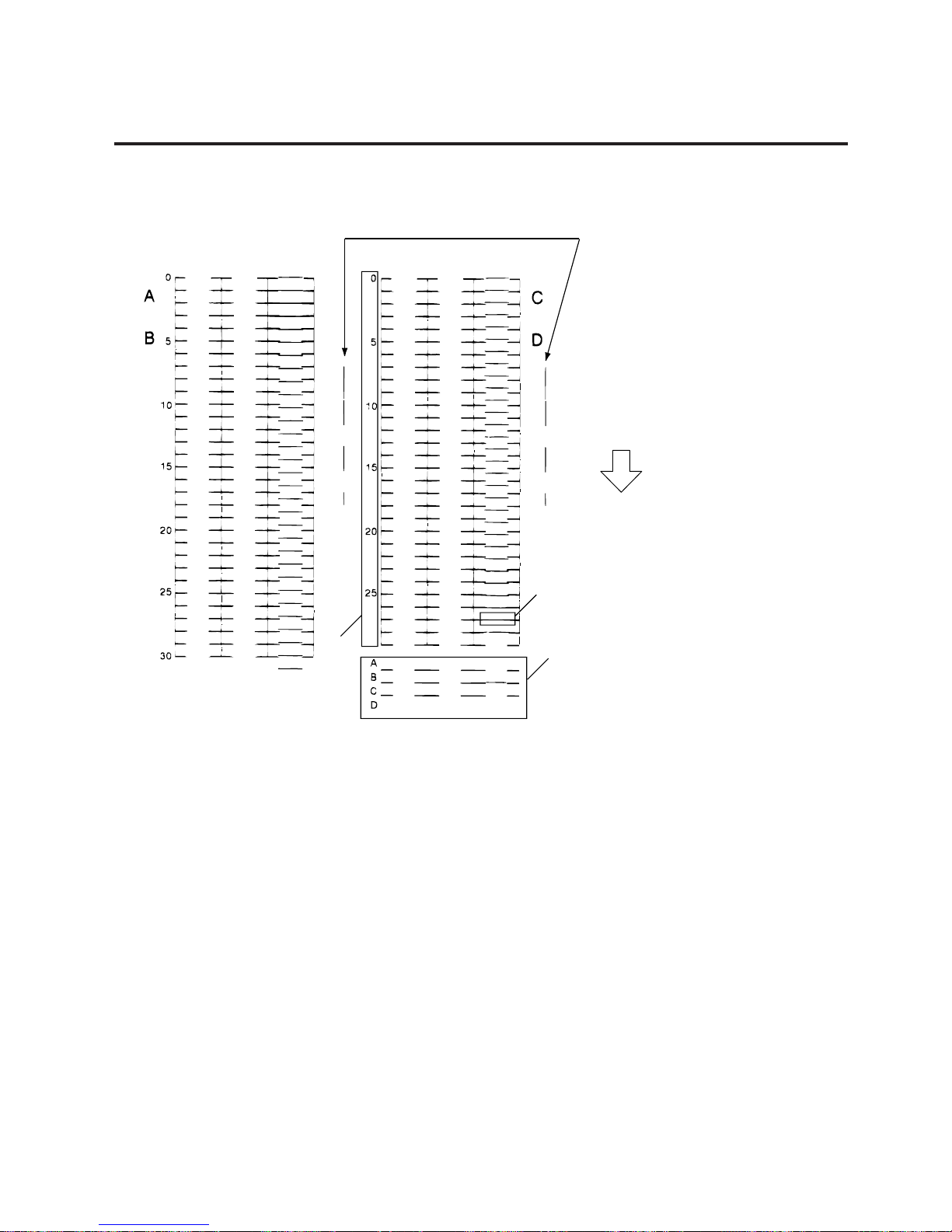
5-29
EO18-33002A
5. DIAG. TEST OPERATION
■ Adjustment example (CB-426)
Y-direction fine adjustment method is explained using 2nd print head.
These lines indicate X-direction
alignment.
(When they align and form an almost
straight line, the adjustment is
completed.)
Y-direction misalignment
A and B : + (plus) direction
C and D: - (minus) direction
1) Check where 2nd print head belongs among rows A~D within the Portion 4.
2) In this example, 2nd print head is printed on the row B. When 2nd print head is printed on the row
A or B, refer to the left print sample.
When row C or D, refer to the right print sample.
3) Check where a 2nd print head aligns with the black line (indicated by 5). Read the scale of the
position (indicated by 6).
4) Enter the alpha-numerics obtained in steps 1) through 3) into the Head Adjust window. In this case,
enter B27.
5) After completing the adjustment and print a sample pattern for confirmation in Section 5.3.3.5
Adjustment Value Confirmation Print. If it is still misaligned, retry the adjustment so that the four
colors mostly align at the center of portions 1 and 4.
Feed
6
5
4
Page 58

5-30
EO18-33002A
5. DIAG. TEST OPERATION
5.3 PARAMETER SETTING MODE
5.3.3.5 Adjustment Value Confirmation Print
The test patterns which shows the status after X/Y-directions adjustment are printed.
Power off
Press the [FEED] key.
Turn on the power while
holding down the [FEED]
key and [PAUSE] key.
<1 DIAG. V1.OA>
Designated number of labels
are issued according to the
print conditions set in Section
5.3.3.1 by pressing the [PAUSE] key.
Press the [FEED] key four times.
CH CKE
PR NT CONDITIONI
<2 PARA METER SET>
Press the [PAUSE] key.
Press the [PAUSE] key.
Press the [PAUSE] key twice.
PO ITIONS
HE D ADJUSTA
Print condition setting display
X and Y-directions fine adjustment display
Page 59

5-31
EO18-33002A
5. DIAG. TEST OPERATION
NOTES: 1. When an error occurs during printing, the error message is displayed and
printing is stopped. The error is cleared by pressing the [PAUSE] key and the
display shows “<2> PARAMETER SET”. Printing is not automatically resumed
after the error is cleared.
2. Extract the 3rd and 4th labels and use them for adjustment.
5.3 PARAMETER SETTING MODE
■ CB-416
■ CB-426
Page 60

5-32
EO18-33002A
5. DIAG. TEST OPERATION
(Revision Date: Dec. 20, 2000)
5.3 PARAMETER SETTING MODE
5.3.4 Print Start Position Fine Adjustment Mode
Using the following procedure, the print start position of each print head can be fine adjusted for
page 1 to page 10.
NOTES: 1. Holding the [FEED] key or [RESTART] key down for more than 0.5 seconds
enables a fast forward.
2. A changed font code is stored in memory by pressing the [PAUSE] key.
3. Adjustment in positive (+) direction makes the print start position moves toward the
feed direction. Negative (-) direction adjustment makes the print start position
moves toward the back feed direction.
Power off
Press the [FEED] key.
Turn on the power while
holding down the [FEED]
key and [PAUSE] key.
<1 DIAG. V1.OA>
<2 PARA METER SET>
Press the [FEED] key.
Press the [FEED] three times.
PO ITIONS
Press the [PAUSE] key .
Print start position adjustment display
BL CK A
HE D AD JUST3A
Select the print start position fine
adjustment value with the [FEED] key
or [RESTART] key.
Press the [PAUSE] key .
Print head selection
Magenta
Black
Yellow
Cyan
Select the print head type with the
[FEED] key or [RESTART] key.
Press the [PAUSE] key .
PA E1 +0.20mm G
Each time the [PAUSE] key is pressed,
the display will change to the fine adjustment
screen for the next page (page 2 to page 10).
[FEED] key
Pressing the [FEED] key one time
is a -0.01 mm change, up to -1.00 mm.
[RESTART] key
Pressing the [PAUSE] key one time is
a +0.01 mm changed, up to +1.00 mm.
Page 61
5-33
EO18-33002A
5. DIAG. TEST OPERATION
(Revision Date: Dec. 20, 2000)
5.3 PARAMETER SETTING MODE
5.3.5 Printer Parameter Setting Mode
5.3.5.1 Character Code Selection
Power off
Press the [FEED] key.
Turn on the power while
holding down the [FEED]
key and [PAUSE] key.
<1 DIAG. V1.OA>
<2 PARA METER SET>
Press the [PAUSE] key.
Press the [FEED] key four times.
PO ITIONS
Press the [PAUSE] key .
Printer parameter setting display
Press the [PAUSE] key.
FO T CODE PC-850N
PR NTER PARAI
Select either character code with
the [FEED] key or [RESTART]
key. (See NOTE 1.)
Press the [FEED] key
and [RESTART] key
at the same time.
Continued on Section 5.3.5.2
Font zero selection.
Character code selection
PC-8
PC-850
NOTES: 1. Holding the [FEED] key or [RESTART] key down for more than 0.5 seconds
enables a fast forward.
2. A changed font code is stored in memory by pressing the [PAUSE] key.
Page 62
5-34
EO18-33002A
5. DIAG. TEST OPERATION
(Revision Date: Dec. 20, 2000)
5.3 PARAMETER SETTING MODE
5.3.5.2 Font Zero Selection
Power off
Press the [FEED] key.
Turn on the power while
holding down the [FEED]
key and [PAUSE] key.
<1 DIAG. V1.OA>
<2 PARA METER SET>
Press the [PAUSE] key.
Press the [FEED] key four times.
PO ITIONS
Press [PAUSE] key twice.
Printer parameter setting display
ZE O FONT 0R
PR NTER PARAI
Zero font selection
0 (without slash)
0 (with slash)
Select either zero font with
the [FEED] key or [RESTART]
key. (See NOTE 1.)
Press the [PAUSE] key.Press the [FEED] key
and [RESTART] key
at the same time.
Continued on Section 5.3.5.3
Control code selection
NOTES: 1. Holding the [FEED] key or [RESTART] key down for more than 0.5 seconds
enables a fast forward.
2. A changed zero font is stored in memory by pressing the [PAUSE] key.
Page 63
5-35
EO18-33002A
5. DIAG. TEST OPERATION
(Revision Date: Dec. 20, 2000)
5.3 PARAMETER SETTING MODE
5.3.5.3 Control Code Selection
Power off
Press the [FEED] key.
Turn on the power while
holding down the [FEED]
key and [PAUSE] key.
<1 DIAG. V1.OA>
<2 PARA METER SET>
Press the [PAUSE] key.
Press the [FEED] key four time.
PO ITIONS
Press [PAUSE] key three times.
Printer parameter setting display
CO E AUTOD
PR NTER PARAI
Control code selection
AUTO : (Automatic selection)
{ , , } : (Manual selection)
ESC, LF, NUL : (Manual selection)
Select control code with the
[FEED] key or [RESTART]
key. (See NOTE 1.)
Press the [PAUSE] key.Press the [FEED] key
and [RESTART] key
at the same time.
Continued on Section 5.3.5.4
Pulse motor speed selection.
NOTES: 1. Holding the [FEED] key or [RESTART] key down for more than 0.5 seconds
enables a fast forward.
2. A changed control code is stored in memory by pressing the [PAUSE] key.
3. When “AUTO”, “ESC”, FL, “NUL”, or “
{ , , }
“ is selected, be sure to select the Non-
transmissive ribbon in the ribbon type selection operation.
Page 64
5-36
EO18-33002A
5. DIAG. TEST OPERATION
(Revision Date: Dec. 20, 2000)
5.3 PARAMETER SETTING MODE
5.3.5.4 Pulse Motor Speed Selection
If a color misalignment occurs when using the ribbon saving function frequently, increase the pulse
motor speed by 4% to prevent the color misalignment.
Power off
Press the [FEED] key.
Turn on the power while
holding down the [FEED]
key and [PAUSE] key.
<1 DIAG. V 1.OA>
<2 PARAMETER S ET>
Press the [PAUSE] key.
Press the [FEED] key and
[RESTART] key at the
same time.
Press the [FEED] key four times.
PO ITIONS
Press [PAUSE] key four time.
Printer parameter setting display
PU SE MOTOR AUTOL
PR NTER PARAI
Pulse motor speed selection
AUTO : Automatically set
104 : Increased by 4%
Press the [FEED] or [RESTART] key to
select the motor type.
Press the [PAUSE] key.
Continued on section 5.3.5.5
Euro Font Code Selection.
NOTES: 1. Usually select “AUTO” for the pulse motor speed. A color misalignment may
occur, however, according to the print patterns even when “AUTO” is selected.
In this case, fine adjust the platen speed in Section 5.3.6 Platen Speed Fine
Adjustment Mode. If the paper becomes slack between the platens with “AUTO”
pulse motor speed, increase the platen speed by pressing the [FEED] key.
2. Select “104” for the pulse motor speed if a misalignment occurs even after the
platen speed fine adjustment, or the printer prints such print patterns that the all
print heads frequently up and down in ribbon saving mode.
3. Holding the [FEED] key or [RESTART] key down for more than 0.5 seconds
enables a fast forward.
4. A changed threshold fine adjustment value is stored in memory by pressing the
[PAUSE] key.
5. The default setting is Auto.
Page 65
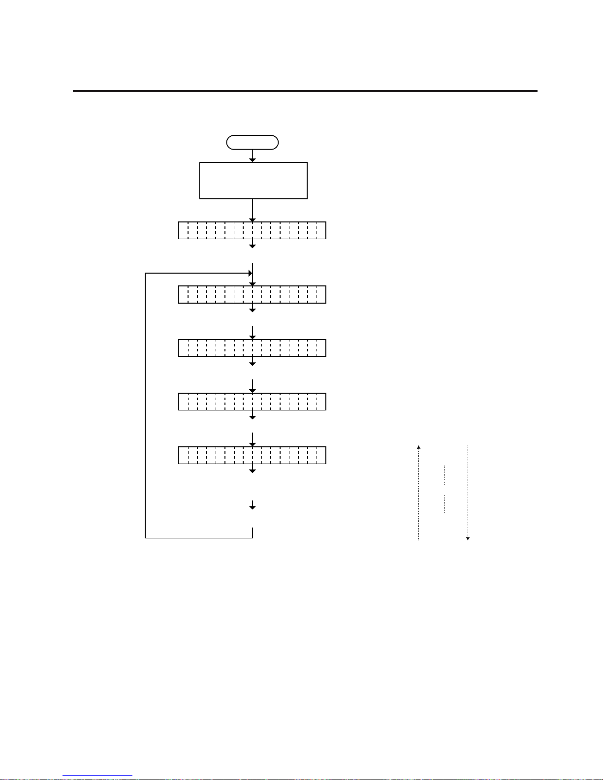
5-37
EO18-33002A
5. DIAG. TEST OPERATION
(Revision Date: Dec. 20, 2000)
5.3 PARAMETER SETTING MODE
5.3.5.5 Euro Font Code Selection
Power off
Press the [FEED] key.
Turn on the power while
holding down the [FEED]
key and [PAUSE] key.
<1 DIAG. V1.OA>
<2 PARA METER SET>
Press the [PAUSE] key.
Press the [PAUSE] key.
Press the [FEED] key four times.
PO ITIONS
Press [PAUSE] key five time.
Printer parameter setting display
EU O ODE BOR
PR NTER PARAI
Euro Font Code selection
Press the [FEED] or [RESTART] key to
select the Euro Font Code.
C
¥ FFH
¥ FEH
¥ B0H
¥ 21H
¥ 20H
[FEED] key
[RESTART] key
NOTES: 1. Holding the [FEED] key or [RESTART] key down for more than 0.5 seconds
enables a fast forward.
2. A changed threshold fine adjustment value is stored in memory by pressing the
[PAUSE] key.
Page 66

5-38
EO18-33002A
5. DIAG. TEST OPERATION
(Revision Date: Dec. 20, 2000)
5.3 PARAMETER SETTING MODE
5.3.6 Platen Speed Fine Adjustment Mode
If a color misalignment occurs due to paper thickness, elasticity, slack, etc., change the platen
speed to prevent the color misalignment.
Power off
Press the [FEED] key.
Turn on the power while
holding down the [FEED]
key and [PAUSE] key.
[FEED] key: pressing the [FEED] key one
time is a -1 step change, up to
-60 steps. (See NOTE 2.)
<1 DIAG. V1.OA>
<2 PARAMETER SET>
[RESTART] key:pressing the [RESTART] key
one time is a +1 step change,
up to +60 steps.
(See NOTE 2.)
+ : Slower
— : Faster
Press the [PAUSE] key.
Press the [PAUSE] key.
Press the [FEED] key five time.
Press [PAUSE] key.
PO ITIONS
PM ADJ. +0
PM ADJ.
Press the [FEED] or
[RESTART] key to fine
adjust the platen motor
voltage. (See NOTE 1.)
Press the [FEED] key
and [RESTART] key
at the same time.
Platen speed fine adjustment display
NOTES: 1. This operation is effective when “AUTO” is selected in Section 5.3.5.4 Pulse
Motor Speed Selection.
2. If a color misalignment occurs even after the platen speed fine adjustment, select
“104” for the pulse motor speed in Section 5.3.5.4 Pulse Motor Speed Selection.
3. Holding the [FEED] key or [RESTART] key down for more than 0.5 seconds
enables a fast forward.
4. Max. fine adjustment
–
60 steps = Platen speed fine adjustment value.
5. A changed motor voltage value is stored in memory by pressing the [PAUSE]
key.
Page 67
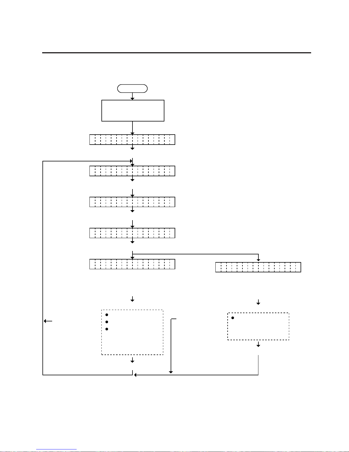
5-39
EO18-33002A
5. DIAG. TEST OPERATION
(Revision Date: Dec. 20, 2000)
5.3 PARAMETER SETTING MODE
5.3.7 Color Designation Mode
Select use or non use of each print head using the following procedure.
Power off
Press the [FEED] key.
Turn on the power while
holding down the [FEED]
key and [PAUSE] key.
<1 DIAG. V1.OA>
<2 PARA METER SET>
Press the [PAUSE] key.
Press [PAUSE] key.
Press the [FEED] key six time.
PO ITIONS
BL CK ONA
HE D SELECTA
Press the [PAUSE] key.
Color designation display
ON : Use
OFF : Not use
MAGENTA
CYAN
YELLOW
Repeat the above
procedure to other
print heads.
Select use or non use of each
print head with the [FEED] or
[RESTART] key.
Press the [FEED] key
and [RESTART] key
at the same time.
Press the [PAUSE] key.
¥CB-416
¥CB-426
HE D1 ONA
ON : Use
OFF : Not use
HEAD2
Repeat the above
procedure to 2nd
print head.
Select use or non use of each
print head with the [FEED] or
[RESTART] key.
Press the [FEED] key
and [RESTART] key
at the same time.
Press the [PAUSE] key.
Press the [PAUSE] key.
NOTE: Changed settings are stored in the memory by pressing the [PAUSE] key.
Page 68

5-40
EO18-33002A
5. DIAG. TEST OPERATION
(Revision Date: Dec. 20, 2000)
5.3 PARAMETER SETTING MODE
5.3.8 Ribbon Type Selection Mode
Power off
Press the [FEED] key.
Turn on the power while
holding down the [FEED]
key and [PAUSE] key.
<1 DIAG. V1.OA>
<2 PARA METER SET>
Press the [PAUSE] key.
Press the [PAUSE] key.
Press the [FEED] key seven times.
PO ITIONS
BL CK F1A
RI BONB
Press the [PAUSE] key.
Ribbon type selection disply
F1 : Standard ribbon
(CR-30xxx-F1)
P1S : Super premium
ribbon
(CR-30xxx-P1S)
MAGENTA
CYAN
YELLOW
Repeat the above
procedure to other
print heads.
Select the ribbon type with
the [FEED] or [RESTART] key.
Press the [FEED] key
and [RESTART] key
at same time.
Press the [PAUSE] key.
¥CB-416
¥CB-426
HA D1 F1E
Press the [PAUSE] key.
F1 : Standard ribbon
(CR-30xxx-F1)
P1S : Super premium
ribbon
(CR-30xxx-P1S)
HEAD2
Repeat the above
procedure to 2nd
print head.
Select the ribbon type with
the [FEED] or [RESTART] key.
Press the [FEED] key
and [RESTART] key
at same time.
Press the [PAUSE] key.
NOTES: 1. Changed settings are stored in the memory by pressing the [PAUSE] key.
2. Ribbon types can be mixed.
3. Ribbon type can be selected by the ribbon type selection command from the PC.
Page 69

5-41
EO18-33002A
5. DIAG. TEST OPERATION
(Revision Date: Dec. 20, 2000)
5.3 PARAMETER SETTING MODE
5.3.9 Supply Holder’s Paper End Sensor Selection
Using the following procedure, use or non use of the supply holder’s paper end sensor is used can
be selected.
NOTES: 1. Holding the [FEED] key or [RESTART] key down for more than 0.5 seconds
enables a fast forward.
2. A changed setting is stored in memory by pressing the [PAUSE] key.
Power off
Press the [FEED] key.
Turn on the power while
holding down the [FEED]
key and [PAUSE] key.
<1 DIAG. V 1.OA>
<2 PARAMETER S ET>
Press the [PAUSE] key.
Press the [FEED] eight times.
PO ITIONS
Press the [PAUSE] key .
Paper end sensor selection display
WI H PAPER END T
SU PL Y HOLDE RP
Paper end sensor selection display
Press the [FEED] key or [RESTART] key to
supply holder’s paper end sensor selection.
Press the [FEED] key or [RESTART] key
at the same time
WITHE PAPER END: Use of paper end sensor
WITHOUT PAPER END: Non use of paper end sensor
Press the [PAUSE] key .
Page 70

5-42
EO18-33002A
5. DIAG. TEST OPERATION
(Revision Date: Dec. 20, 2000)
5.3 PARAMETER SETTING MODE
5.3.10 Resolution Selection
Using the following procedure, the resolution can be selected between Normal Mode and Fine
Mode.
NOTES: 1. Holding the [FEED] key or [RESTART] key down for more than 0.5 seconds
enables a fast forward.
2. A changed setting is stored in memory by pressing the [PAUSE] key.
3. If the Fine Mode is selected without using the printer driver exclusively for the fine
mode, print could be shrunk in the vertical direction.
Power off
Press the [FEED] key.
Turn on the power while
holding down the [FEED]
key and [PAUSE] key.
<1 DIAG. V 1.OA>
<2 PARAMETER S ET>
Press the [PAUSE] key.
Press the [FEED] nine times.
PO ITIONS
Press the [PAUSE] key .
Resolution selection display
NO MA L MODE R
RE OLUTIO N S
Resolution selection display
Press the [FEED] key or [RESTART] key to
resolution of printer.
Press the [FEED] key or [RESTART] key
at the same time
NORMAL MODE: 305 X 305 dpi
FINE MODE: 305 X 610 dpi
Press the [PAUSE] key .
Page 71

5-43
EO18-33002A
5. DIAG. TEST OPERATION
(Revision Date: Apr. 20 ‘99)
5.4 TEST PRINT MODE
5.4 TEST PRINT MODE
Test print mode contains normal test print and process test print.
5.4.1 Normal Test Print
Eight kinds of test prints are provided in the test print mode. When performing the test print, 8
parameters should be set. The default parameter at power on is as below:
• ISSUE COUNT : 1
• PRINT SPEED : 6”/sec.
• SENSOR : Transmissive sensor (Feed gap sensor)
• Reverse feed : with reverse feed
• Quality : High (without ribbon save)
• TYPE : Batch (without cut)
• LABEL LENGTH : 102 mm
• PAPER FEED : Feed
Operating procedure for the test mode is provided below.
Power off
Press the [FEED] key twice.
Turn on the power while
holding down the [FEED]
key and [PAUSE] key.
<1 DIAG. V1.OA>
<3 TEST PRINT>
Press the [PAUSE] key.
Select "Print Condition"
by pressing the
[PAUSE] key.
Press the [FEED]
key and [RESTART]
key at the same
time.
Press the
[FEED] key or
[RESTART]
key.
(See NOTE 1.)
To .
Press the
[RESTART]
key.
Continued
on section
5.4.2
Process
Test Print.
PR NT CONDITIONI
IS UE COUNT 1S
A
From on
the next page.
C
To be continued on
of the next page.
B
ISSUE COUNT
PRINT SPEED
SENSOR
TYPE
Reverse FEED
QUALITY
LABEL LENGTH
PAPER FEED
Set the print count
Page 72

5-44
EO18-33002A
5. DIAG. TEST OPERATION
5.4 TEST PRINT MODE
Press the [PAUSE] key. (See NOTE 3.)
Set the print count from those at the
right by pressing the [FEED] key or
[RESTART] key. (See NOTE 2.)
Select the print speed from those at
the right by pressing the [FEED]
key or [RESTART] key.
To be continued on
of the next page.
B
To of the
preceding page.
C
Press the [PAUSE] key. (See NOTE 3.)
Select the sensor type from
those at the right by pressing
the [FEED] key or [RESTART]
key. (See NOTE 2 and 4.)
Set the print speed
PR NT SPEED 6"/sI
Set the sensor type
SE SOR TRANS.N
Press the [PAUSE] key. (See NOTE 3.)
5000 (Print count 5000)
6"/sec.
4"/sec.
1000 (Print count 1000)
500 (Print count 500)
100 (Print count 100)
50 (Print count 50)
10 (Print count 10)
5 (Print count 5)
3 (Print count 3)
1 (Print count 1)
Press the [FEED]
key and [RESTART]
key at the same
time.
To of the
preceding page.
C
Press the [FEED]
key and [RESTART]
key at the same
time.
To of the
preceding page.
C
Press the [FEED]
key and [RESTART]
key at the same
time.
TRANSMISSIVE
REFLECTIVE
(black mark sensor)
NONE
(consecutive form)
(feed gap sensor)
From of the preceding page.B
Page 73

5-45
EO18-33002A
5. DIAG. TEST OPERATION
(Revision Date: Apr. 20 ‘99)
5.4 TEST PRINT MODE
Select the issue mode type from
those at the right by pressing
the [FEED] key or [RESTART]
key. (See NOTE 2 .)
From of the preceding page.B
To be continued on
of the next page.
B
Press the [PAUSE] key. (See NOTE 3.)
Select the label length from
those at the right by pressing
the [FEED] key or [RESTART]
key. (See NOTE 2.)
Set the issue mode type
TY E [S]NO CUTP
Set the media reverse feed
BA K FEED YESC
Press the [PAUSE] key. (See NOTE 3.)
To of the
preceding page.
C
Press the [FEED]
key and [RESTART]
key at the same
time.
To of the
preceding page.
C
Press the [FEED]
key and [RESTART]
key at the same
time.
YES (with reverse feed)
NO (without reverse feed)
Press the [PAUSE] key. (See NOTE 3.)
Select the media feed from those
at the right by pressing the
[FEED] key or [RESTART] key.
(See NOTE 2.)
Press the [PAUSE] key. (Feed one media.)
Set the print quality
QU LITY HIGHTA
To of the
preceding page.
C
Press the [FEED]
key and [RESTART]
key at the same
time.
NORMAL (with ribbon save)
HIGHT (without ribbon save)
[C] Auto-cut mode
(Issue and cutting)
[S] Standard mode
(Batch printing without cut)
Page 74
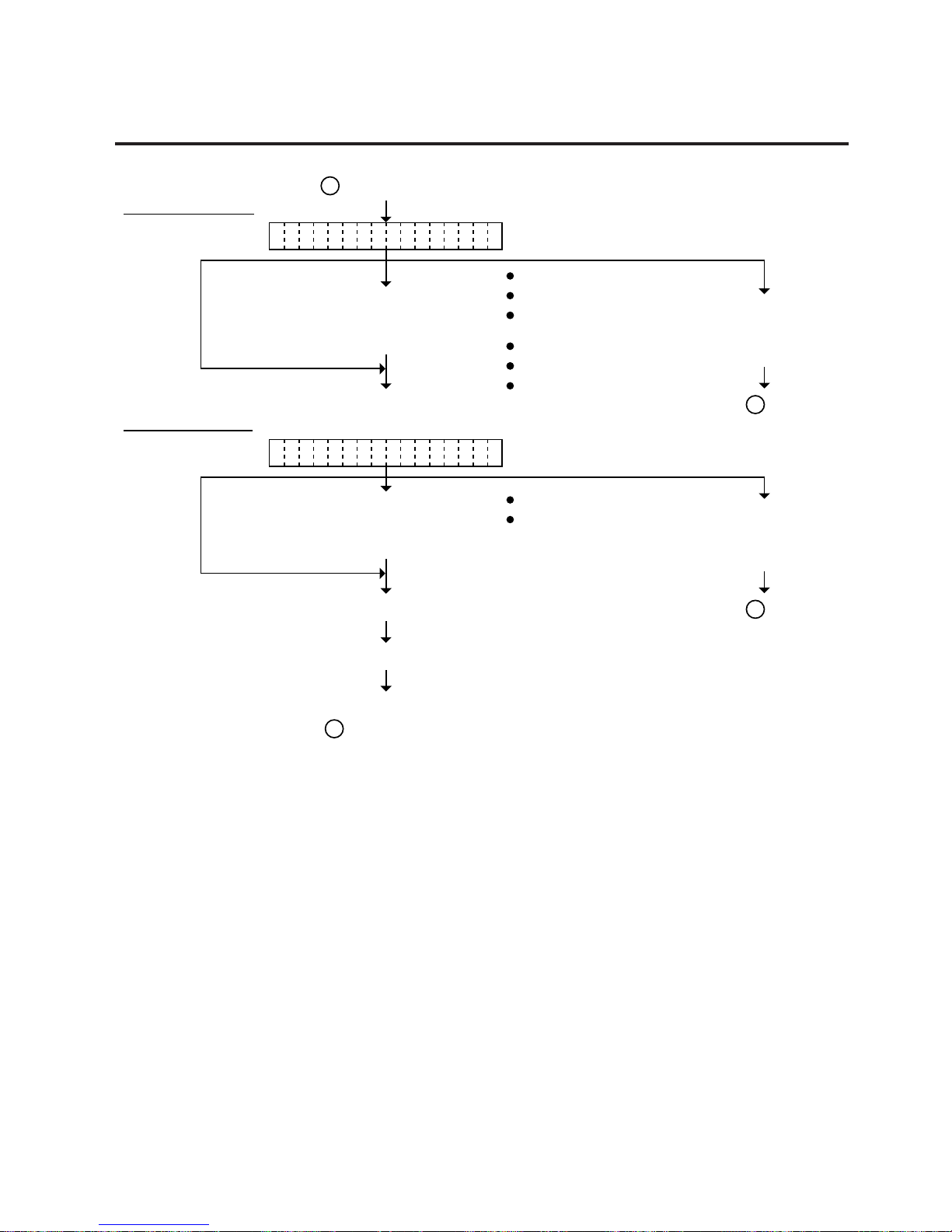
5-46
EO18-33002A
5. DIAG. TEST OPERATION
5.4 TEST PRINT MODE
To be continued on
of the next page.
B
Press the [PAUSE] key. (See NOTE 3.)
Select the label length from
those at the right by pressing
the [FEED] key or [RESTART]
key. (See NOTE 4 and 5.)
Set the label length
LA EL LEN. 102mmB
From of the preceding page.
To of the
preceding page.
C
Press the [FEED]
key and [RESTART]
key at the same
time.
300 (Label length 300 mm)
299 (Label length 299 mm)
298 (Label length 298 mm)
~
12 (Label length 12 mm)
11 (Label length 11 mm)
10 (Label length 10 mm)
Press the [PAUSE] key. (See NOTE 3.)
Select the media feed from those
at the right by pressing the
[FEED] key or [RESTART] key.
(See NOTE 2.)
Press the [PAUSE] key. (Feed one media.)
Set the media feed
PA ER FEEDP
To of the
preceding page.
C
Press the [FEED]
key and [RESTART]
key at the same
time.
PAPER FEED
PAPER NO FEED
B
Page 75
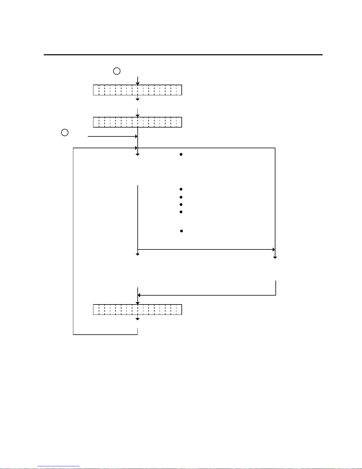
5-47
EO18-33002A
5. DIAG. TEST OPERATION
5.4 TEST PRINT MODE
PR NT CONDITIONI
Press the [PAUSE] key.
<3 TEST PRINT>
Press the [PAUSE] key.
<3 TEST PRINT>
From of the preceding page.
B
From of the
preceding page.
A
Select the test print from
those at the right by
pressing the [FEED] key
or [RESTART] key.
A designated number of
test prints are issued when
pressing the [PAUSE] key.
(See NOTE 7.)
CHARACTERS
BAR CODE
AUTO PRINT (TRANS.)
Color bar print
SLANT LINE (1DOT,3DOT)
K : BLACK
Process test print/
Transmissive sensor
AUTO PRINT (REFLECT.)
Process test print/
Reflective sensor
M : MAGENTA
C : CYAN
Y : YELLOW
Press the [FEED] key
and [RESTART] key at
the same time.
CB-416
1 : 1st print head
2 : 2nd print head
CB-426
NOTES: 1. When there is no change to the print condition, select one of the test print options
to issue the test print.
2. Holding the [FEED] key or [RESTART] key down for more than 0.5 seconds
enables a fast forward.
3. A selected print condition is activated when the [PAUSE] key is pressed.
4. When the feed gap sensor is selected, the gap between labels becomes 2mm long.
5. A label size greater than the image buffer length cannot be designated. The image
buffer length differs according to memory size. If designated, the printer prints in
the image buffer, or the printer stops because of an error.
6. Pressing the [FEED] key changes the label length -1 mm, pressing the [RESTART]
key changes +1 mm.
Page 76
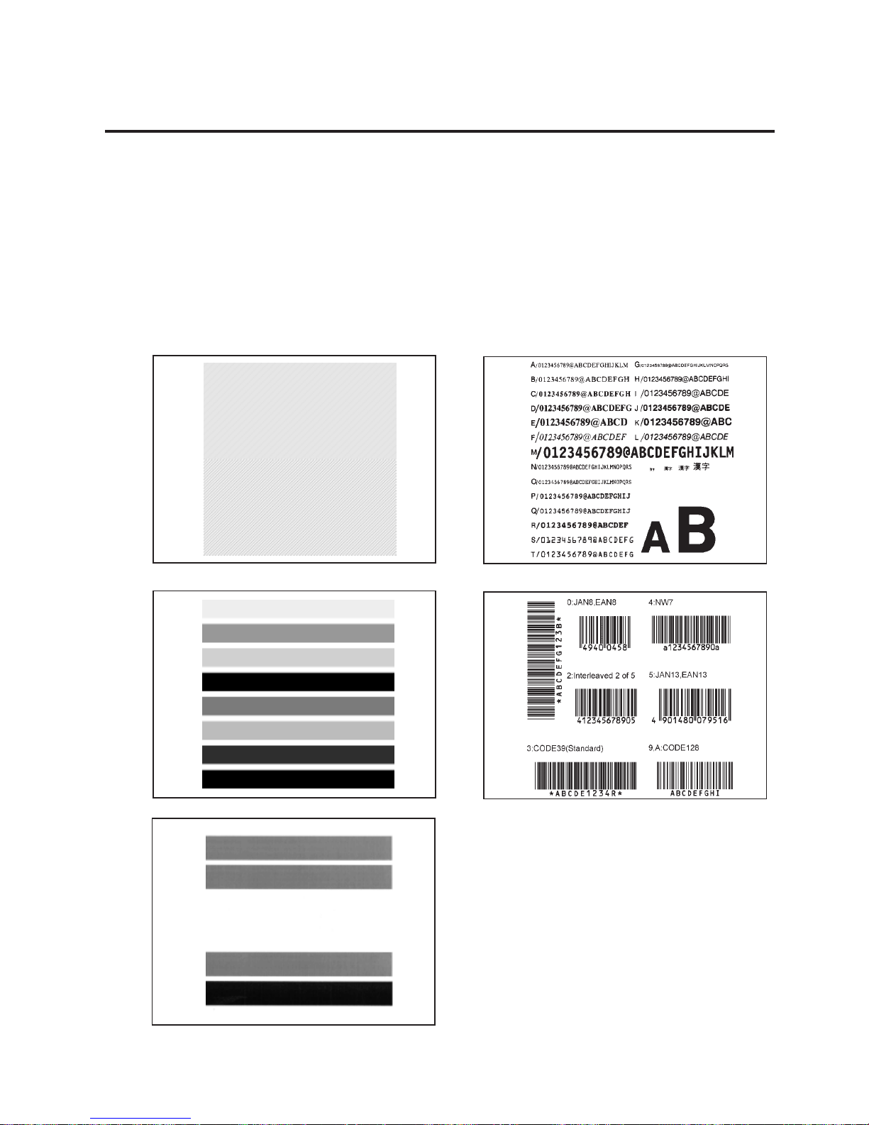
5-48
EO18-33002A
5. DIAG. TEST OPERATION
5.4 TEST PRINT MODE
7. When an error occurs during a test print, the error message is displayed and
printing is stopped. The error is cleared by pressing the [PAUSE] key and the
display shows “<3> TEST PRINT”. Printing is not automatically resumed after the
error is cleared.
8. When “AUTO PRINT” is selected, 3 pcs. of the slant line labels, color bar print
labels and character labels are printed respectively after one label is fed.
9. Changed parameter settings are effective by pressing the [PAUSE] key until the
power is turned off.
10. Fine adjustment values are effective to test print.
■ Test Print Sample
• Slant line • Charactor
• Color bar print (CB-416) • Bar code
• Color bar print (CB-426)
Page 77
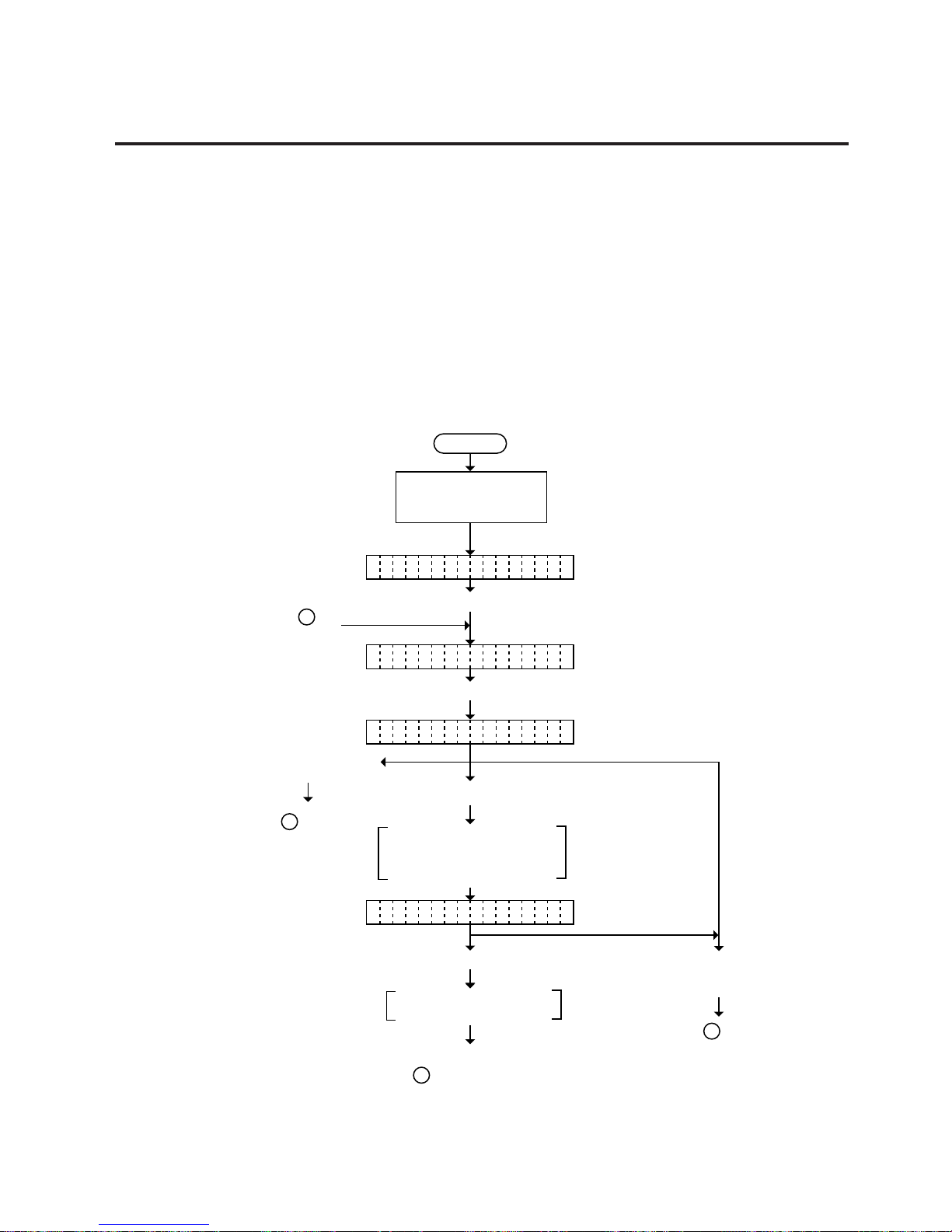
5-49
EO18-33002A
5. DIAG. TEST OPERATION
5.4.2 Process Test Print
In the process test print, the test print is automatically performed under the following conditions.
• OPERATION : One label feed. Slant line print (4 colors), character print, color
bar print
• ISSUE COUNT : 3 labels each
• PRINT SPEED : 6 inches/sec.
• SENSOR : Transmissive sensor (feed gap sensor) or reflective sensor
(black mark sensor)
• TYPE : Batch (without cut)
• REVERSE FEED : Yes
• ISSUE MODE : High quality print
• LABEL LENGTH : 102 mm
Operating procedure for the test mode is provided below.
5.4 TEST PRINT MODE
Power off
Press the [FEED] key twice.
Turn on the power while
holding down the [FEED]
key and [PAUSE] key.
<1 DIAG. V1.OA>
<3 TEST PRINT>
Press the [PAUSE] key.
Press the [RESTART] key.
After feeding one label, each
color's slant lines are printed
on 3 labelsColor bars are
printed on 3 labels.
Press the [RESTART]
key.
PR NT CONDITIONI
AU O PRINT(REFL)T
Press the [PAUSE] key.
From on
the next page.
C
To on the
preceding page.
A
To be continued on
of the next page.
B
To of the
preceding page.
C
Press the [FEED] key
and [RESTART] key
at the same time.
Color bars are printed on
3 labels.
Page 78
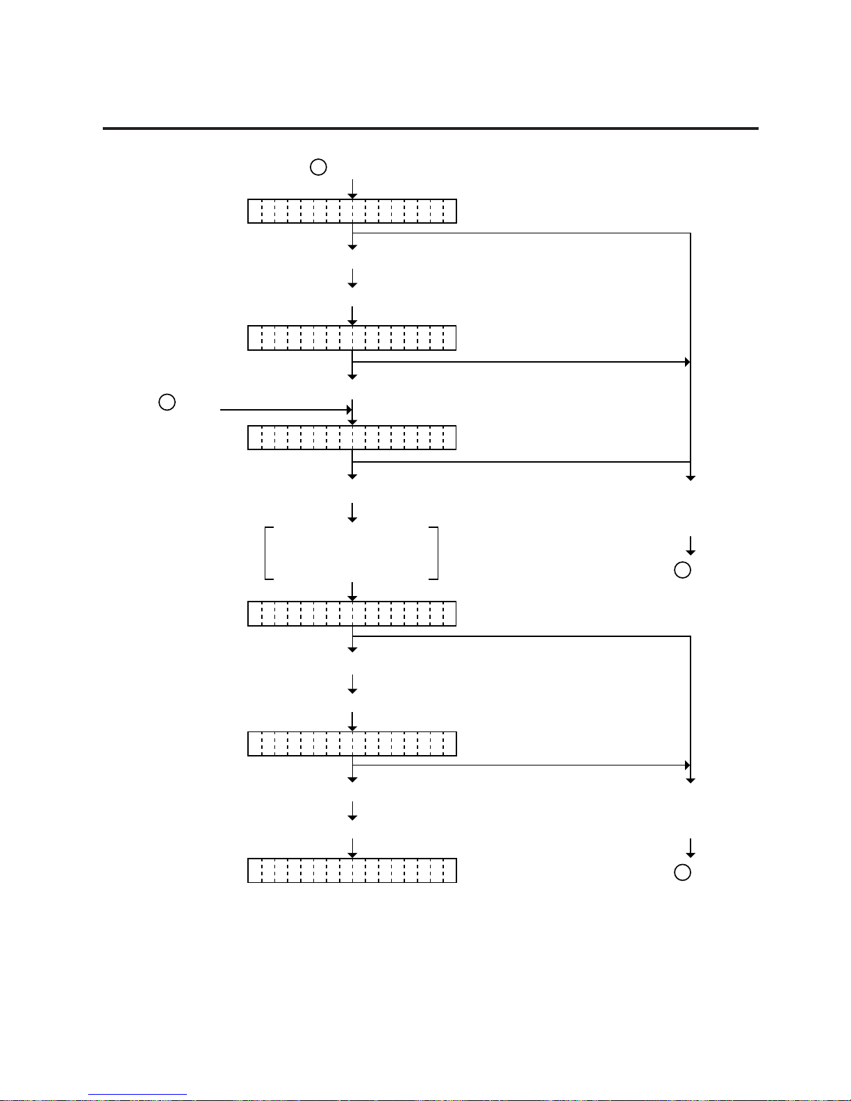
5-50
EO18-33002A
5. DIAG. TEST OPERATION
5.4 TEST PRINT MODE
AU O PRINT(REFL)T
To of the
preceding page.
C
From of the next page.B
<3 TEST PRINT>
Press the [PAUSE] key.
Press the [PAUSE] key.
[Characters are printed on 3 labels.]
Press the [PAUSE] key.
AU O PRINT(TRAN)T
<3 TEST PRINT>
[Characters are printed on 3 labels.]
Press the [PAUSE] key.
[Color bars are printed on 3 labels.]
Press the [PAUSE] key.
AU O PRINT(TRAN)T
AU O PRINT(TRAN)T
From of the
preceding page.
A
Press the [FEED] key
and [RESTART] key
at the same time.
To of the
preceding page.
C
Press the [FEED] key
and [RESTART] key
at the same time.
After feeding one label,
each color's slant lines
are printed on 3 labels.
Page 79

5-51
EO18-33002A
5. DIAG. TEST OPERATION
5.5 RAM CLEAR MODE
In RAM clear mode, various data written on the EEP-ROM can be initialized. There are three clear
functions; Maintenance counter clear, parameter clear and print step clear in the parameter setting mode.
After referring to the following table specify and clear or initialize the data.
■ RAM Clear Mode Table
5.5 RAM CLEAR MODE
Mode Name
NO RAM CLEAR
MAINTE. CNT CLEAR
PRINT STEP CLEAR
Function
If you enter the RAM clear mode by mistake, specify this mode to
eacape from the RAM clear mode without excuting RAM clear.
After replacing the print head, cutter module, ribbon feed/rewind motor,
solenoid and CPU PC Board, clear the maintanance counter.
The following data will be cleared to zero. Confirmation can be made
through the maintenance counter procedure in self test mode. (See
NOTE 1)
ITEM
Total feed length
Print distance (CB-416:black, CB-426:1st)
Print distance
(CB-416:magenta, CB-426:2nd)
Print distance (CB-416:cyan)
Print distance (CB-416:yellow)
Cut count
Head up/down (CB-416:black, CB-426:1st)
Head up/down
(CB-416:magenta, CB-426:2nd)
Head up/down (CB-416:cyan)
Head up/down (CB-416:yellow)
Ribbon motor driving hours (CB-416:black, CB-426:1st)
Ribbon motor driving hours (CB-416:magenta, CB-426:2nd)
Ribbon motor driving hours
(CB-416:cyan)
Ribbon motor driving hours
(CB-416:yellow)
RS-232C hardware error count
Instantaneous power failure count
Initial value
0 Km
0 Km
0 Km
0 Km
0 Km
0 time
0 time
0 time
0 time
0 time
0 hours
0 hours
0 hours
0 hours
0 times
0 times
ITEM
Print head run distance (CB-416:black, CB-426:1st)
Print head run distance (CB-416:magenta, CB-426:2nd)
Print head run distance (CB-416:cyan)
Print head run distance (CB-416:yellow)
Initial value
0.0 Km
0.0 Km
0.0 Km
0.0 Km
Page 80
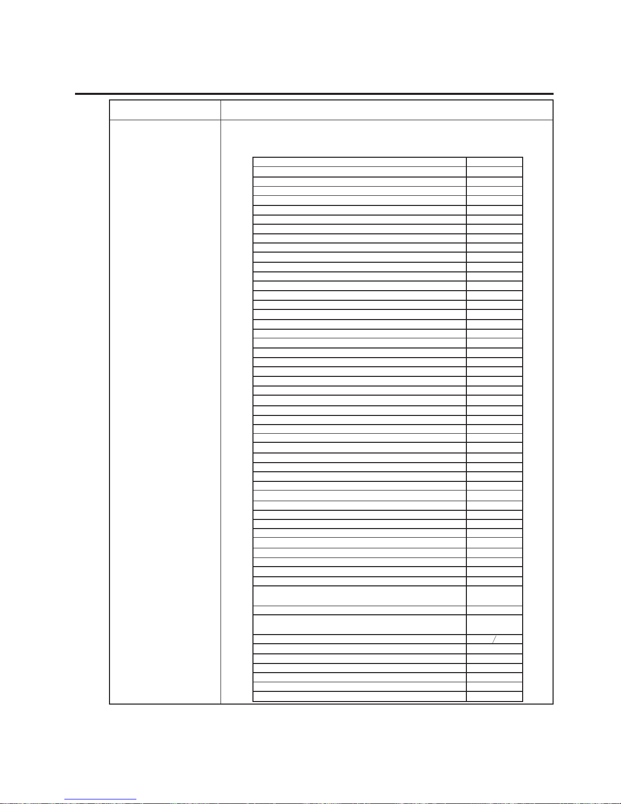
5-52
EO18-33002A
5. DIAG. TEST OPERATION
ITEM
Print position fine adjustment (PC)
Cut position fine adjustment (PC)
Reverse feed distance adjustment (PC)
Print stop position fine adjustment (PC)
X-direction fine adjustment (CB-416:black, CB-426:1st) (PC)
X-direction fine adjustment (CB-416:magenta, CB-426:2nd) (PC)
X-direction fine adjustment
(CB-416:cyan) (PC)
X-direction fine adjustment (CB-416:yellow) (PC)
Y-direction fine adjustment (CB-416:black, CB-426:1st) (PC)
Y-direction fine adjustment (CB-416:magenta, CB-426:2nd) (PC)
Y-direction fine adjustment (CB-416:cyan) (PC)
Y-direction fine adjustment
(CB-416:yellow) (PC)
Print tone fine adjustment (CB-416:black, CB-426:1st) (PC)
Print tone fine adjustment (CB-416:magenta, CB-426:2nd) (PC)
Print tone fine adjustment
(CB-416:cyan) (PC)
Print tone fine adjustment
(CB-416:yellow) (PC)
Ribbon take-up motor voltage fine adjustment (CB-416:black, CB-426:1st) (PC)
Ribbon take-up motor voltage fine adjustment (CB-416:magenta, CB-426:2nd)
(PC)
Ribbon take-up motor voltage fine adjustment (CB-416:cyan) (PC)
Ribbon take-up motor voltage fine adjustment (CB-416:yellow) (PC)
Ribbon feed motor voltage fine adjustment (CB-416:black, CB-426:1st)
(PC)
Ribbon feed motor voltage fine adjustment (CB-416:magenta, CB-426:2nd)
(PC)
Ribbon feed motor voltage fine adjustment (CB-416:cyan) (PC)
Ribbon feed motor voltage fine adjustment (CB-416:yellow)
(PC)
Print start position fine adjustment (KEY)
Cut position fine adjustment (KEY)
Reverse feed distance fine adjustment (KEY)
Print stop position fine adjustment (KEY)
Print tone fine adjustment (CB-416:black, CB-426:1st)(KEY)
Print tone fine adjustment (CB-416:magenta, CB-426:2nd) (KEY)
Print tone fine adjustment
(CB-416:cyan) (KEY)
Print tone fine adjustment (CB-416:yellow) (KEY)
X-coordinate fine adjustment
Character code selection
Font zero selection
Control code selection
Label pitch
Sensor type
Feed speed
Cutter
Status response
Ribbon saving function
Top first/bottom first print
Reverse feed
Ribbon type
Color designation
Platen speed
Euro font code
Print Start Position Fine Adjustment (Page 1 ~ Page 10) (Black)
Print Start Position Fine Adjustment (Page 1 ~ Page 10) (Magenta)
Print Start Position Fine Adjustment (Page 1 ~ Page 10) (Cyan)
Print Start Position Fine Adjustment (Page 1 ~ Page 10) (Yellow)
Supply Holder’s Paper End Sensor Selection
Printer Resolution Selection
(Revision Date: Dec. 20, 2000)
5.5 RAM CLEAR MODE
Mode Name
PARAMETER CLEAR
Function
This clear should be employed when initializing the following parameters
to the settings before shipment. Confirmation can be made through the
automatic diagnostic procedure in self test mode. (See NOTE 1)
Initial value
0.0 mm
0.0 mm
0.0 mm
0.0 mm
0.00 mm
0.00 mm
0.00 mm
0.00 mm
0.00 mm
0.00 mm
0.00 mm
0.00 mm
0 step
0 step
0 step
0 step
0 step
0 step
0 step
0 step
0 step
0 step
0 step
0 step
0.0 mm
0.0 mm
0.0 mm
0.0 mm
0 step
0 step
0 step
0 step
0.0 mm
PC-850
Without slash
AUTO
102.0 mm
Transmissive
6 inch/sec
No
Yes
No
Bottom first
No
CR-30xxx-F1
(Standard)
All
AUTO (no
adjustment)
B0H
0.00 mm
0.00 mm
0.00 mm
0.00 mm
WITH PAPER END
NORMAL END
NOTES: 1. Total media distance covered (TL FEED) and the adjustment value for the sensors
cannot be cleared.
2. For data to be cleared in the RAM clear mode, refer to the RAM clear mode table.
Page 81
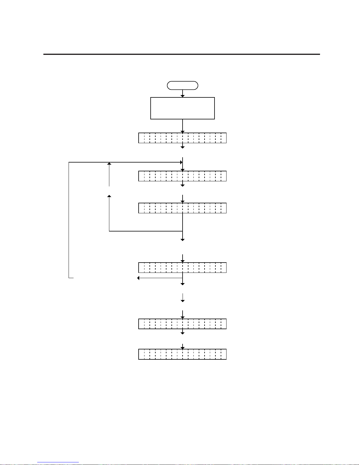
5-53
EO18-33002A
5. DIAG. TEST OPERATION
5.5 RAM CLEAR MODE
5.5.1 Maintenance Counter Clear
Power off
Press the [FEED] key three times.
Turn on the power while
holding down the [FEED]
key and [PAUSE] key.
<1 DIAG. V1.OA>
Turn off the power (NOTE 1)
CO PLETEM
<4 RAM CLEAR>
Press the [PAUSE] key.Press the [PAUSE] key.
Press the [FEED] key
and [RESTART] key
at the same time.
Press the [FEED] key.
(or press the [RESTART] key three times.)
Press the [FEED] key.
NO RAM CLEAR
MA NTE.CNT C LEARI
Press the [PAUSE] key.
NOTES: Confirm that “COMPLETE” is displayed, then turn the power off.
Page 82

5-54
EO18-33002A
5. DIAG. TEST OPERATION
5.5 RAM CLEAR MODE
5.5.2 Parameter Clear
Power off
Press the [FEED] key three times.
Turn on the power while
holding down the [FEED]
key and [PAUSE] key.
<1 DIAG. V1.OA>
Turn off the power (NOTE 1)
CO PLETEM
<4 RAM CLEAR>
Press the [PAUSE] key.Press the [PAUSE] key.
Press the [FEED] key
and [RESTART] key
at the same time.
Press the [FEED] key twice.
(or press the [RESTART] key twice.)
Press the [PAUSE] key.
NO RAM CLEAR
PA AMETER CLEARR
NOTE: Confirm that “COMPLETE” is displayed, then turn the power off.
Page 83
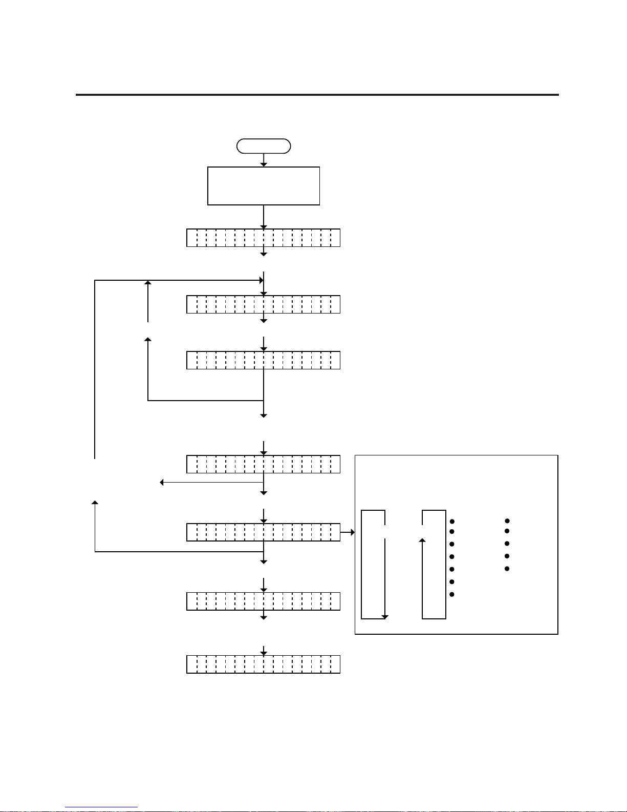
5-55
EO18-33002A
5. DIAG. TEST OPERATION
5.5 RAM CLEAR MODE
5.5.3 Print Step clear
Power off
Press the [FEED] key three times.
Turn on the power while
holding down the [FEED]
key and [PAUSE] key.
<1 DIAG. V1.OA>
AL COLORL
<4 RAM CLEAR>
Press the [PAUSE] key.
Press the [PAUSE] key.
Press the [FEED] key
and [RESTART] key
at the same time.
Press the [FEED] key three times.
(or press the [RESTART] key.)
Select the item to be cleared by
pressing the [FEED] and
[RESTART] keys.
Press the [PAUSE] key.
Press the [PAUSE] key.
Turn the power off.
(Refer to the NOTE below.)
CO PLETEM
NO RAM CLEAR
PR NT STEP CLEARI
[FEED] [PAUSE]
ALL COLOR
BLACK
CYAN
MAGENTA
YELLOW
NONE
CB-416
ALL COLOR
HEAD1
HEAD2
NONE
CB-426
NOTE: Confirm that “COMPLETE” is displayed prior to the power off.
Page 84

6-1
6. PROGRAM DOWNLOAD
RS-232C
or
Centronics
EO18-33002
(Revision Date: Jan. 20 '99)
6.1 FLOPPY DISK
6. PROGRAM DOWNLOAD
The main program for the printer has been written onto the flash ROM. If the main program is upgraded,
due to the addition/change of the specification, download the main program from the PC to the printer
with the download floppy disks and RS-232C or Centronics interface.
6.1 FLOPPY DISK
(1) Media: 3.5 inch (2DD)
(2) Disk: Program Loader Setup Disks 1 and 2
Program Data Disk
6.2 SETUP
6.3 OUTLINE OF THE PROGRAM DOWNLOAD PROCEDURE
(1) Install the Program Loader (Program Loader Setup Disk 1 and 2) in the PC.
(2) Copy the prog.bin file in the Program Data Disk to the directory created in step (1).
(3) Set the DIP SW3 on the VR PC board to ON and turn the printer power ON.
The printer LCD display shows “PROGRAM LOAD.”
(4) Run the Program Loader.
(5) Start the download.
(6) After the download is completed, turn the printer power OFF and restore the DIP SW3 to the former
position.
6.4 DOWNLOAD PROCEDURE
1) Install the program loader (Setup Disks 1 and 2) in the PC as indicated on the display.
NOTE: The PC should operate Windows 95.
Program Loader FDK
(Sample)
CB-416-T3-QQ/QP
Program Loader
SETUP DISK 1
25th November 1998
FMRM0049901
V001.000
CB-416-T3-QQ/QP
Program Loader
SETUP DISK 2
25th November 1998
FMRM005001
V001.000
CB-416-T3
▲
▲▲
▲
Page 85

6-2
6. PROGRAM DOWNLOAD
EO18-33002
(Revision Date: Jan. 20 '99)
6.4 DOWNLOAD PROCEDURE
2) Run the Setup.exe in the Program Loader FDK.
3) When the Program Loader has been installed, the following message will appear.
NOTE: Once the Program Loader has been installed, it is not required to be installed on the same
PC each time the new program is downloaded.
Page 86

6-3
6. PROGRAM DOWNLOAD
4) Copy the prog.bin file in the Program Data FDK to the directory of Program Loader.
Program Data FDK
(Sample)
EO18-33002
(Revision Date: Jan. 20 '99)
6.4 DOWNLOAD PROCEDURE
CB-418-T3
CB-416-T3-QQ/QP
Program Data DISK
#V1.0
28th August 1998
FMRM0048401:9200,D300
V001.000
The directory is created in the Program Files as a default.
5) Set the DIP SW3 on the VR PC board to ON, and then turn the printer power on.
The printer enters the download mode and the LCD display shows "PROGRAM LOAD".
6) Run the download program on the PC. Select the Program Loader from the start menu to start the
download program.
Page 87

6-4
6. PROGRAM DOWNLOAD
7) Select the output device from COM1, COM2, or LPT1.
(COM1 and COM2: RS232C, LPT1: Centronics)
Select Program for the Target. Usually, Boot program is not downloaded.
EO18-33002
(Revision Date: Jan. 20 '99)
6.4 DOWNLOAD PROCEDURE
8) Click on the [Start] button to start the program download.
While the program is being downloaded, the printer LCD shows "PROGRAM LOAD".
Also, the following message will appear on the PC screen.
Page 88

6-5
6. PROGRAM DOWNLOAD
9) When the communication between the PC and the printer is completed, the following message will
appear on the PC screen. However, in case of Centronics interface, the program write onto the flash
ROM has not been completed yet.
NOTE: DO NOT turn the printer power off until "COMPLETE" is displayed on the LCD.
EO18-33002
(Revision Date: Jan. 20 '99)
6.4 DOWNLOAD PROCEDURE
10) When the printer LCD turns to “COMPLETE”, the downloading is completed.
Downloading will take about the following time.
• Centronics I/F: 10 minutes
• RS232C I/F: 20 minutes
 Loading...