

Page 1

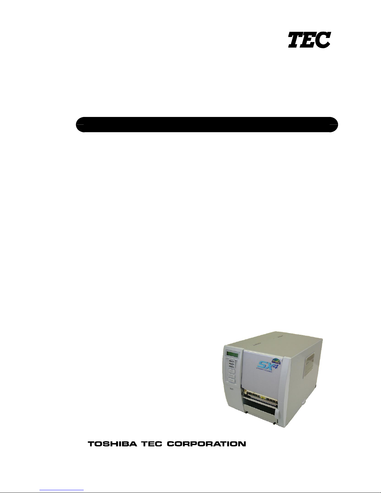
TEC Thermal Printer
B-SX4T/SX5T SERIES
Document No. EO0-33013AUM
Original Jan., 2003
(Revised Feb., 2003)
User's Manual
TABLE OF CONTENTS
B-SX5T OWNER’S MANUAL ............................... EO1-33036
PRODUCT DESCRIPTION...................................EO10-33013A
MAINTENANCE MANUAL....................................EO18-33012A
B-SX4T OWNER’S MANUAL ............................... EO1-33034
Page 2

Precaution
This service manual is intended for use by service technicians, and designed as a guide for repair
& maintenance. The m anual is intended to promote smooth service operations of the product in
the market place. It is not intended for any other purpose such as development or product
specifications. For questions reg arding development or product specif ications, please cont act the
TOSHIBA TEC department in char ge.
This manual may be changed or revised without notice. If you f ind any misprints or omissions,
please contact the TOSHIBA TEC Ser vice Dept. (Ohito) promptly (Facsimile No. 0558- 76- 9842).
TOSHIBA TEC cannot be held responsible for any trouble which have been caused by misprints
or omissions.
The following related manuals contain additional specific information on using B-SX4T/SX5T
SERIES and can be ref erred to f or mor e detailed inform ation available from T OSHIBA T EC sales
headquarters.
• Interface/Communication Manual
• Supply Manual
• Specifications
Safety Summary
Personal safety in handling or mainta ining the equipment is extremely important. W arnings and
Cautions necessary for safe handling are included in this manual. All warnings and cautions
contained in this manual and written inside or outside of the printer should be read and understood
before handling or maintaining the equipment.
Never modify the machine. Except for the addition of options as specif ically provided for in the
service manual, change or m odifications to the machine are not approved. Unauthorized changes
or modifications may not comply with your country's safety standards.
Safety Precaution
Electrical equipment is dangerous. Electrical shock from such equipment can cause death. Never
operate electrical equipment unless authorized to do so by a responsible aut hor ity.
In emergency work on electrical equipment is authorized, be sure that it is perform ed in st rict
compliance with approved safety regulations.
The following safety precautions will help to ensure proper use of the printer:
• Turn off the printer before 1) opening the top cover for any reason, 2) attaching/detaching
any cable and memory cards.
• Disconnect the power cord whenever you are working inside the printer.
• Keep your work environment static free.
Page 3
TEC Thermal Printer
B-SX4T-QQ/QP
Owner's Manual
Page 4

CE Compliance (for EU only)
This product complies with the requirements of EMC and Low Voltage Directives including their
amendments.
VORSICHT:
•
Schallemission: unter 70dB (A) nach DIN 45635 (oder ISO 7779)
•
Die für das Gerät Vorgesehene Steckdose muß in der Nähe des Gerätes und leicht zugänglich sein.
Copyright © 2003
by TOSHIBA TEC CORPORATION
All Rights Reserved
570 Ohito, Ohito-cho, Tagata-gun, Shizuoka-ken, JAPAN
Centronics is a registered trademark of Centronics Data Computer Corp.
Microsoft is a registered trademark of Microsoft Corporation.
Windows is a trademark of Microsoft Corporation.
As an ENERGY STAR® Partner, TOSHIBA TEC has determined that this
product meets the ENERGY STAR
®
guidelines for energy efficiency.
-- Outline of the International ENERGY STAR® Office Equipment Program --
The International ENERGY STAR
®
Office Equipment Program is an international program that
promotes energy saving through the penetration of energy efficient computers and other office
equipment. The program backs the development and dissemination of products with functions that
effectively reduce energy consumption. It is an open sy st em in which business proprietors can
participate voluntarily. The targeted products are office equipment such as computers, monitors,
printers, facsimiles, copiers, scanners, and multifunction devices. Their standards and logos are
uniform among participating nations.
E
NERGY STAR is a U.S. registered mark.
This equipment has been tested and found to comply with the limits for a Class A digital device,
pursuant to Part 15 of the FCC Rules. These limits are designed to provide reasonable rotection
against harmful interference when the equipment is operated in a commercial environment. This
equipment generates, uses, and can radiate radio frequency energy and, if not installed and sed in
accordance with the instruction manual, may cause harmful interference to radio communications.
Operations of this equipment in a residential area is likely to cause harmful interference in which case
the user will be required to correct the interference at his own expense.
(for USA only)
Changes or modifications not expressly approved by manufacturer for compliance could void the
user’s authority to operate the equipment.
“This Class A digital apparatus meets all requirements of the Canadian Interference-Causing
Equipment Regulations.”
“Cet appareil numérique de la classe A respecte toutes les exigences du Règlement sur le matériel
brouilleur du Canada.”
(for CANADA only)
Page 5
Safety Summary
ENGLISH VERSION EO1-33034
( ) i
6DIHW\6XPPDU\
Personal safety in handling or maintaining the equipment is extremely important. Warnings and Cautions
necessary for safe handling are included in this manual. All warnings and cautions contained in this manual
should be read and understood before handling or maintaining the equipment.
Do not attempt to effect repairs or modifications to this equipment. If a fault occurs that cannot be rectified
using the procedures described in this manual, turn off the power, unplug the machine, then contact your
authorised TOSHIBA TEC representative for assistance.
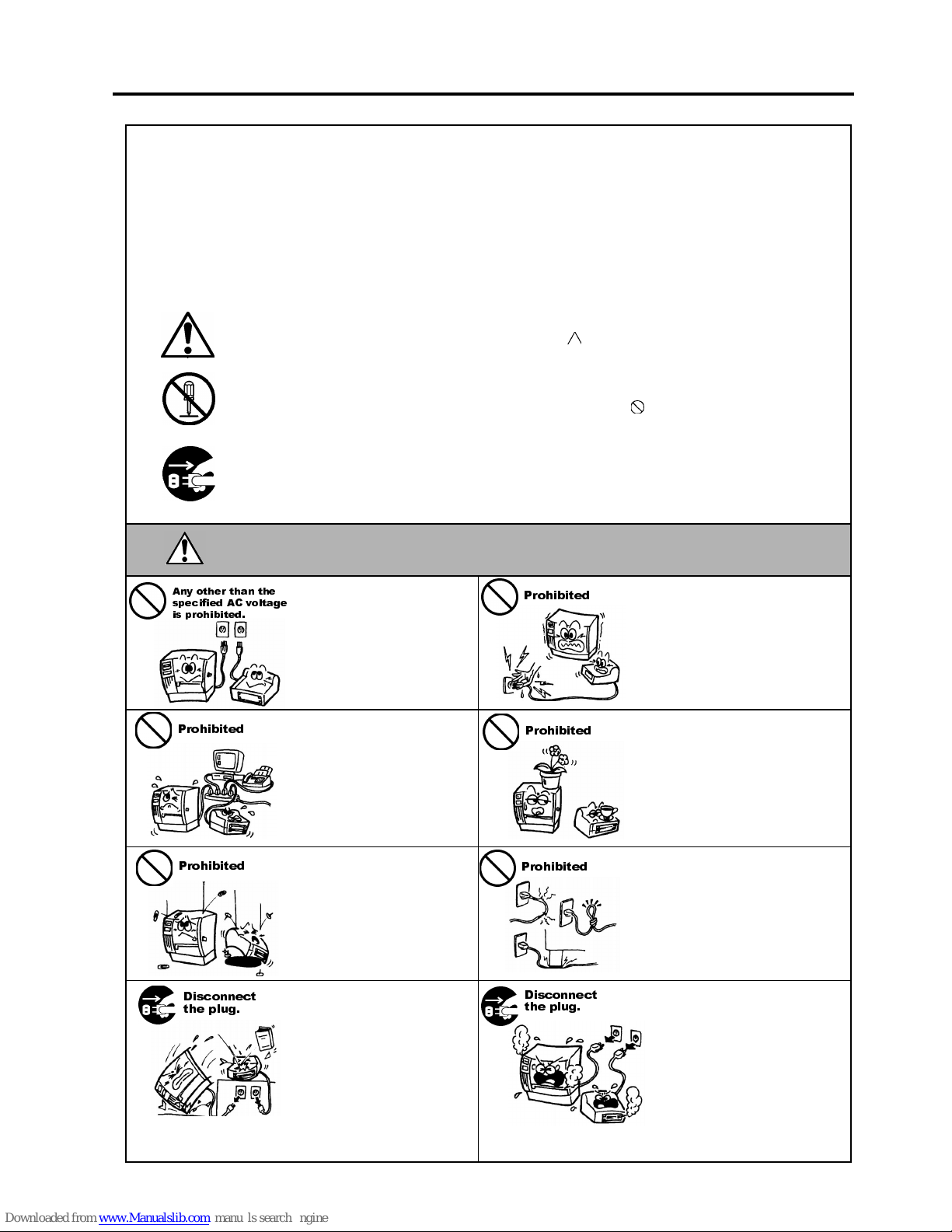
0HDQLQJVRI(DFK6\PERO
This symbol indicates warning items (including cautions).
Specific warning contents are drawn inside the symbol.
(The symbol on the left indicates a general caution.)
This symbol indicates prohibited actions (prohibited items).
Specific prohibited contents are drawn inside or near the
symbol.
(The symbol on the left indicates “no disassembling”.)
This symbol indicates actions which must be performed.
Specific instructions are drawn inside or near the ● symbol.
(The symbol on the left indicates “disconnect the power cord plug from the outlet”.)
This indicates that there is the risk of death or serious injury if the
machines are improperly handled contrary to this indication.
Do not use voltages other than
the voltage (AC) specified on the
rating plate, as this may cause
fire
or
electric shock
.
Do not plug in or unplug the power
cord plug with wet hands as this
may cause
electric shock
.
If the machines share the same
outlet with any other electrical
appliances that consume large
amounts of power, the voltage
will fluctuate widely each time
these appliances operate. Be sure
to provide an exclusive outlet for
the machine as this may cause
fire
or
electric shock
.
Do not place metal objects or
water-filled containers such as
flower vases, flower pots or mugs,
etc. on top of the machin es. If
metal objects or spilled liquid enter
the machines, this may cause
fire
or
electric shock
.
Do not insert or drop metal,
flammable or other foreign
objects into the machines through
the ventilation slits, as this may
cause
fire
or
electric shock
.
Do not scratch, damage or modify
the power cords. Also, do not
place heavy objects on, pull on, or
excessively bend the cords, as this
may cause
fire
or
electrical shock.
If the machines are dropped or
their cabinets damaged, first turn
off the power switches and
disconnect the power cord plugs
from the outlet, and then contact
your authorised TOSHIBA TEC
representative for assistance.
Continued use of the machine in
that condition may cause
fire
or
electric shock
.
Continued use of the machines in
an abnormal condition such as
when the machines are producing
smoke or strange smells may cause
fire
or
electric shock
. In these
cases, immediately turn off the
power switches and disconnect the
power cord plugs from the outlet.
Then, contact your authorised
TOSHIBA TEC representative for
assistance.
:$51,1*
$Q\ RWKHU WKDQ WKH
VSHFLILHG $& YROWDJH
LV SURKLELWHG
3URKLELWHG
3URKLELWHG
3URKLELWHG
3URKLELWHG
3URKLELWHG
'LVFRQQHFW
WKH SOXJ
'LVFRQQHFW
WKH SOXJ
Page 6

Safety Summary
ENGLISH VERSION EO1-33034
( ) ii
If foreign objects (metal
fragments, water, liquids) enter
the machines, first turn off the
power switches and disconnect
the power cord plugs from the
outlet, and then contact your
authorised TOSHIBA TEC
representative for assistance.
Continued use of the machine in
that condition may cause
fire
or
electric shock
.
When unplugging the power cords,
be sure to hold and pull on the plug
portion. Pulling on the cord portion
may cut or expose the internal wires
and cause
fire
or
electric shock
.
Ensure that the equipment is
properly grounded. Extension
cables should also be grounded.
Fire
or
electric shock
could
occur on improperly grounded
equipment.
Do not remove covers, repair or
modify the machine by yourself.
You may be
injured
by high
voltage, very hot parts or sharp
edges inside the machine.
This indicates that there is the risk of personal
Injury
or
damage
to
objects if the machines are improperly handled contrary to this indication.
Precautions
The following precautions will help to ensure that this machine will continue to function correctly.
●
Try to avoid locations that have the following adverse conditions:
* Temperatures out of the specification * Direct sunlight * High humidity
* Shared power source * Excessive vibration * Dust/Gas
●
The cover should be cleaned by wiping with a dry cloth or a cloth slightly dampened with a mild
detergent solution. NEVER USE THINNER OR ANY OTHER VOLATILE SOLVENT on the plastic
covers.
●
USE ONLY TOSHIBA TEC SPECIFIED paper and ribbons.
●
DO NOT STORE the paper or ribbons where they might be exposed to direct sunlight, high
temperatures, high humidity, dust, or gas.
●
Ensure the printer is operated on a level surface.
●
Any data stored in the memory of the printer could be lost during a printer fault.
●
Try to avoid using this equipment on the same power supply as high voltage equipment or equipment
likely to cause mains interference.
●
Unplug the machine whenever you are working inside it or cleaning it.
●
Keep your work environment static free.
●
Do not place heavy objects on top of the machines, as these items may become unbalanced and fall
causing injury.
●
Do not block the ventilation slits of the machines, as this will cause heat to build up inside the
machines and may cause fire.
●
Do not lean against the machine. It may fall on you and could cause injury.
●
Care must be taken not to injure yourself with the printer paper cutter.
●
Unplug the machine when it is not used for a long period of time.
●
Place the machine on a stable and level surface.
Request Regarding Maintenance
●
Utilize our maintenance services.
After purchasing the machine, contact your authorised TOSHIBA TEC representative for assistance
once a year to have the inside of the machine cleaned. Otherwise, dust will build up inside the
machines and may cause a fire or a malfunction. Cleaning is particularly effective before humid rainy
seasons.
●
Our preventive maintenance service performs the periodic checks and other work required to maintain
the quality and performance of the machines, preventing accidents beforehand.
For details, please consult your authorised TOSHIBA TEC representative for assistance.
●
Using insecticides and other chemicals
Do not expose the machines to insecticides or other volatile solvents. This will cause the cabinet or
other parts to deteriorate or cause the paint to peel.
&$87,21
'LVFRQQHFW
WKH SOXJ
&RQQHFW D
JURXQGLQJ ZLUH
'LVFRQQHFW
WKH SOXJ
1R
GLVDVVHPEOLQJ
Page 7

ENGLISH VERSION EO1-33034
TABLE OF CONTENTS
Page
1. PRODUCT OVERVIEW..........................................................................................................E1-1
1.1 Introduction....................................................................................................................E1-1
1.2 Features.........................................................................................................................E1-1
1.3 Unpacking......................................................................................................................E1-1
1.4 Accessories ..................................................................................................................E1-2
1.5 Appearance ...................................................................................................................E1-3
1.5.1 Dimensions................................................................................................................E1-3
1.5.2 Front View.................................................................................................................. E1-3
1.5.3 Rear View ..................................................................................................................E1-3
1.5.4 Operation Panel......................................................................................................... E1-4
1.5.5 Interior........................................................................................................................ E1-4
2. PRINTER SETUP ...................................................................................................................E2-1
2.1 Precautions....................................................................................................................E2-1
2.2 Procedure before Operation ..........................................................................................E2-2
2.3 Fitting the Fan Filter.......................................................................................................E2-2
2.4 Connecting the Cables to Your Printer ..........................................................................E2-3
2.5 Connecting the Power Cord...........................................................................................E2-4
2.6 Turning the Printer ON/OFF........................................................................................... E2-5
2.6.1 Turning ON the Printer............................................................................................... E2-5
2.6.2 Turning OFF the Printer.............................................................................................E2-5
2.7 Loading the Media .........................................................................................................E2-6
2.8 Loading the Ribbon...................................................................................................... E2-11
2.9 Inserting the Optional PCMCIA Cards .........................................................................E2-12
2.10 Test Print .....................................................................................................................E2-13
3. ON LINE MODE......................................................................................................................E3-1
3.1 Operation Panel.............................................................................................................E3-1
3.2 Operation.......................................................................................................................E3-2
3.3 Reset .............................................................................................................................E3-2
3.4 Dump Mode ...................................................................................................................E3-3
4. MAINTENANCE......................................................................................................................E4-1
4.1 Cleaning.........................................................................................................................E4-1
4.1.1 Print Head/Platen/Sensors......................................................................................... E4-1
4.1.2 Covers and Panels.....................................................................................................E4-2
4.1.3 Optional Cutter Module..............................................................................................E4-2
4.2 Care/Handling of the Media and Ribbon........................................................................ E4-3
5. TROUBLESHOOTING............................................................................................................ E5-1
5.1 Error Messages .............................................................................................................E5-1
5.2 Possible Problems.........................................................................................................E5-2
5.3 Removing Jammed Media.............................................................................................E5-3
5.4 Threshold Setting...........................................................................................................E5-4
Page 8

ENGLISH VERSION EO1-33034
APPENDIX 1 SPECIFICATIONS.................................................................................................EA1-1
A1.1 Printer ..........................................................................................................................EA1-1
A1.2 Options ........................................................................................................................EA1-2
A1.3 Media...........................................................................................................................EA1-2
A1.3.1 Media Type.......................................................................................................EA1-2
A1.3.2 Detection Area of the Transmissive Sensor.....................................................EA1-3
A1.3.3 Detection Area of the Reflective Sensor...........................................................EA1-4
A1.3.4 Effective Print Area...........................................................................................EA1-4
A1.4 Ribbon .........................................................................................................................EA1-5
APPENDIX 2 MESSAGES AND LEDS.......................................................................................EA2-1
APPENDIX 3 INTERFACE..........................................................................................................EA3-1
APPENDIX 4 PRINT SAMPLES..................................................................................................EA4-1
GLOSSARIES
INDEX
CAUTION!
1. This manual may not be copied in whole or in part without prior written permission of TOSHIBA TEC.
2. The contents of this manual may be changed without notification.
3. Please refer to your local Authorised Service representative with regard to any queries you may have in
this manual.
This is a Class A product. In a domestic environment this product may cause radio interference in
which case the user ma
y
be required to take adequate measures.
WARNING!
Page 9

1. PRODUCT OVERVIEW
ENGLISH VERSION EO1-33034
1.1 Introduction
E1- 1
1. PRODUCT OVERVIEW
1.1 Introduction
1.2 Features
1.3 Unpacking
Thank you for choosing the TEC B-SX4T series thermal printer. This
Owner’s Manual contains from general set-up through how to confirm
the printer operation using a test print, and should be read carefully to
help gain maximum performance and life from your printer. For most
queries please refer to this manual and keep it safe for future reference.
Please contact your TOSHIBA TEC representative for further
information concerning this manual.
This printer has the following features:
• The print head block can be opened providing smooth loading of
media and ribbon.
• Various kinds of media can be used as the media sensors can be
moved from the centre to the left edge of the media.
• When the optional interface board is installed, Web functions such as
remote maintenance and other advanced network features are
available.
• Superior hardware, including the specially developed 8 dots/mm (203
dots/inch) thermal print head which will allow very clear print at a
printing speed of 76.2 mm/sec. (3 inches/sec.), 152.4 mm/sec. (6
inches/sec.), or 254.0 mm/sec. (10 inches/sec.).
• Besides the optional Cutter Module, there is also an optional Strip
Module, Ribbon Saving Module, PCMCIA Interface Board,
Expansion I/O Interface Board, LAN Interface Board, and the USB
Interface Board.
Unpack the printer as per the Unpacking Instructions supplied with the
printer.
NOTES:
1. Check for damage or
scratches on the printer.
However, please note that
TOSHIBA TEC shall have no
liability for any damage of
any kind sustained during
transportation of the product.
2. Keep the cartons and pads
for future transportation of
the printer.
Page 10

1. PRODUCT OVERVIEW
ENGLISH VERSION EO1-33034
1.4 Accessories
E1- 2
1.4 Accessories
When unpacking the printer, please make sure all the following
accessories are supplied with the printer.
US Power Cord (1 pc.)
(P/No. FBCB0030203)
QQ model only
CD-ROM (1 pc.)
QQ (P/No.: 7FM00331000)
QP (P/No.: 7FM00254000)
EU Power Cord (1 pc.)
(P/No.EKA-0030001)
QP model only
Fan Filter (1 pc.)
(P/No. FMBB0036801)
Page 11
1. PRODUCT OVERVIEW
ENGLISH VERSION EO1-33034
1.5 Appearance
E1- 3
1.5 Appearance
1.5.1 Dimensions
1.5.2 Front View
1.5.3 Rear View
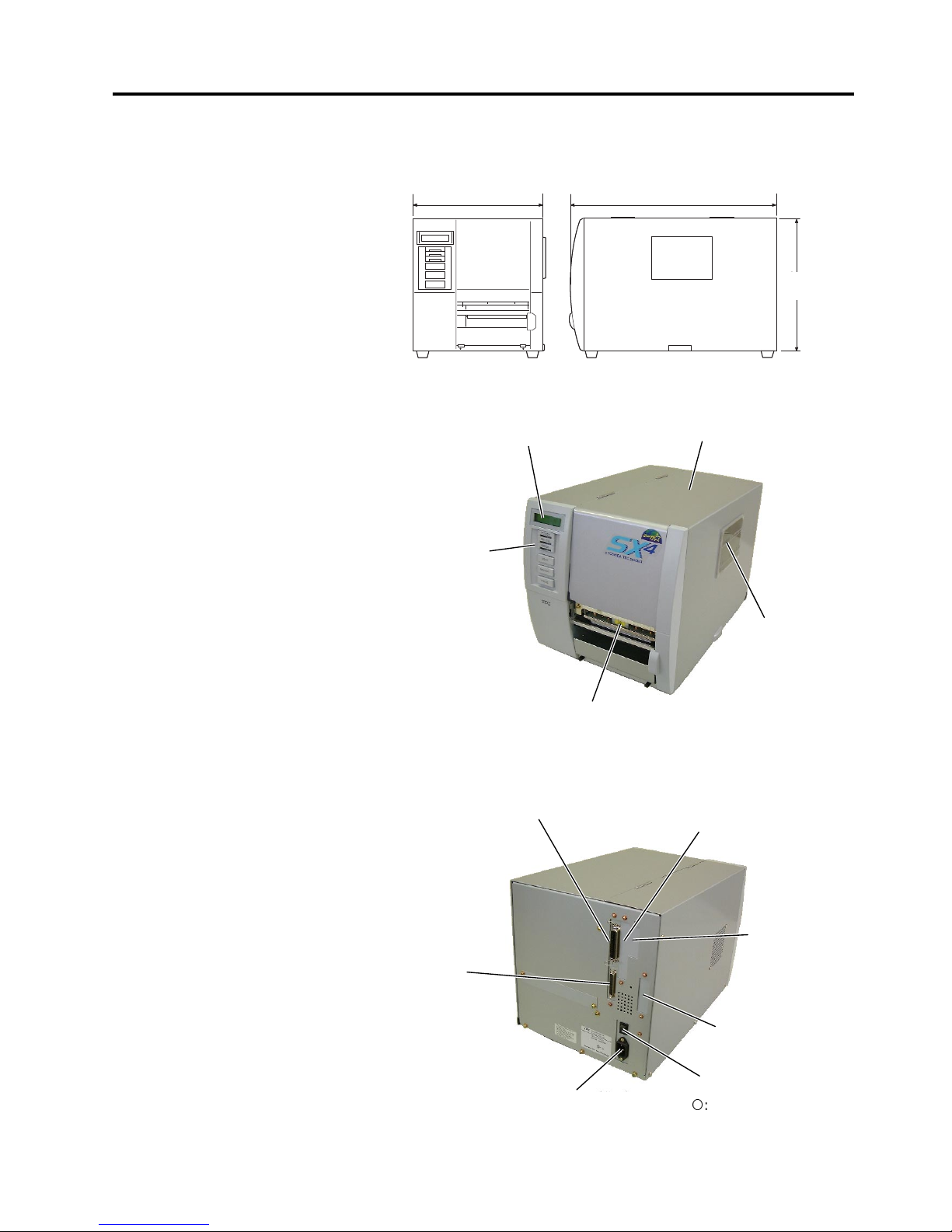
The names of the parts or units introduced in this section are used in the
following chapters.
Dimensions in mm (inches)
LCD Message Display
Operation Panel
Power Switch
{
: OFF
|: ON
Media Outlet
Top Cover
Expansion I/O
Interface Connector
(Option)
Serial Interface
Connector (RS-232C)
Parallel Interface
Connector (Centronics)
Supply Window
PCMCIA Card Slot (Option),
USB Connector (Option), or
LAN Connector (Option)
AC Power Inlet
291 460
308
308
(12.1)
291 (11.5)
460 (18.1)
USB Connector
(Option) or LAN
Connector (Option)
Page 12
1. PRODUCT OVERVIEW
ENGLISH VERSION EO1-33034
1.5 Appearance
E1- 4
1.5.4 Operation Panel
1.5.5 Interior
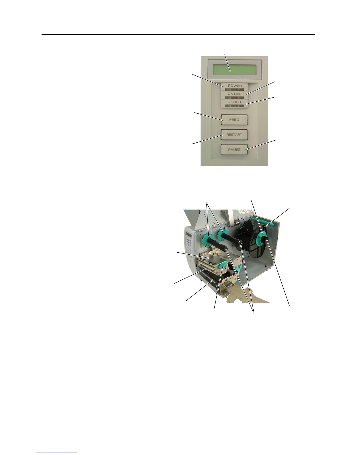
Please see Section 3.1 for further information about the Operation Panel.
LCD Message Display
ON LINE LED
(Green)
ERROR LED
(Red)
[PAUSE]
key
POWER LED
(Green)
[FEED]
ke
y
[RESTART]
ke
y
Ribbon Stoppe
r
Print Head Block
Head Lever
Ribbon Shaft
Supply Holder
Locking Ring
Supply Shaft
Print Head
Platen
Page 13

2. PRINTER SETUP
ENGLISH VERSION EO1-33034
2.1 Precautions
E2- 1
2. PRINTER SETUP
2.1 Precautions
This section outlines the procedures to setup your printer prior to its
operation. The section includes precautions, connecting cables,
assembling accessories, loading media and ribbon, inserting the optional
memory card, and performing a test print.
To insure the best operating environment, and to assure the safety of the
operator and the equipment, please observe the following precautions.
• Operate the printer on a stable, level, operating surface in a location
free from excessive humidity, high temperature, dust, vibration or
direct sunlight.
• Keep your work environment static free. Static discharge can cause
damage to delicate internal components.
• Make sure that the printer is connected to a clean source of AC
Power and that no other high voltage devices that may cause line
noise interference are connected to the same mains.
• Assure that the printer is connected to the AC mains with a three-
prong power cable that has the proper ground (earth) connection.
• Do not operate the printer with the cover open. Be careful not to
allow fingers or articles of clothing to get caught into any of the
moving parts of the printer especially the optional cutter mechanism.
• Make sure to turn off the printer power and to remove the power cord
from the printer whenever working on the inside of the printer such
as changing the ribbon or loading the media, or when cleaning the
printer.
• For best results, and longer printer life, use only TOSHIBA TEC
recommended media and ribbons.
• Store the media and ribbons in accordance with their specifications.
• This printer mechanism contains high voltage components; therefore
you should never remove any of the covers of the machine as you
may receive an electrical shock. Additionally, the printer contains
many delicate components that may be damaged if accessed by
unauthorised personnel.
• Clean the outside of the printer with a clean dry cloth or a clean cloth
slightly dampened with a mild detergent solution.
• Use caution when cleaning the thermal print head as it may become
very hot while printing. Wait until it has had time to cool before
cleaning. Use only the TOSHIBA TEC recommended print head
cleaner to clean the print head.
• Do not turn off the printer power or remove the power plug while the
printer is printing or while the ON LINE lamp is blinking.
Page 14
2. PRINTER SETUP
ENGLISH VERSION EO1-33034
2.2 Procedure before Operation
E2- 2
2.2 Procedure before
Operation
2.3 Fitting the Fan Filter
This section describes the outline of the printer setup.
1.
Unpack the accessories and printer from the box.
2.
Refer to Safety Precautions in this manual and set up the printer at a
proper location.
3.
Fit the Fan Filter to the printer. (Refer to Section 2.3.)
4.
The host computer must have a serial, Centronics parallel, USB or
LAN port. (Refer to Section 2.4.)
5.
Be sure to insert the power cord plug into an AC outlet. (Refer to
Section 2.5.)
6.
Load the media. (Refer to Section 2.7.)
7.
Adjust the position of the Feed Gap Sensor or Black Mark Sensor
depending on the media being used. (Refer to Section 2.7.)
8.
Load the ribbon. (Refer to Section 2.8.)
9.
Turn the power ON. (Refer to Section 2.6.)
10.
Perform a test print. (Refer to Section 2.10.)
11.
Install the Printer Drivers. (Refer to the Printer Driver Manual.)
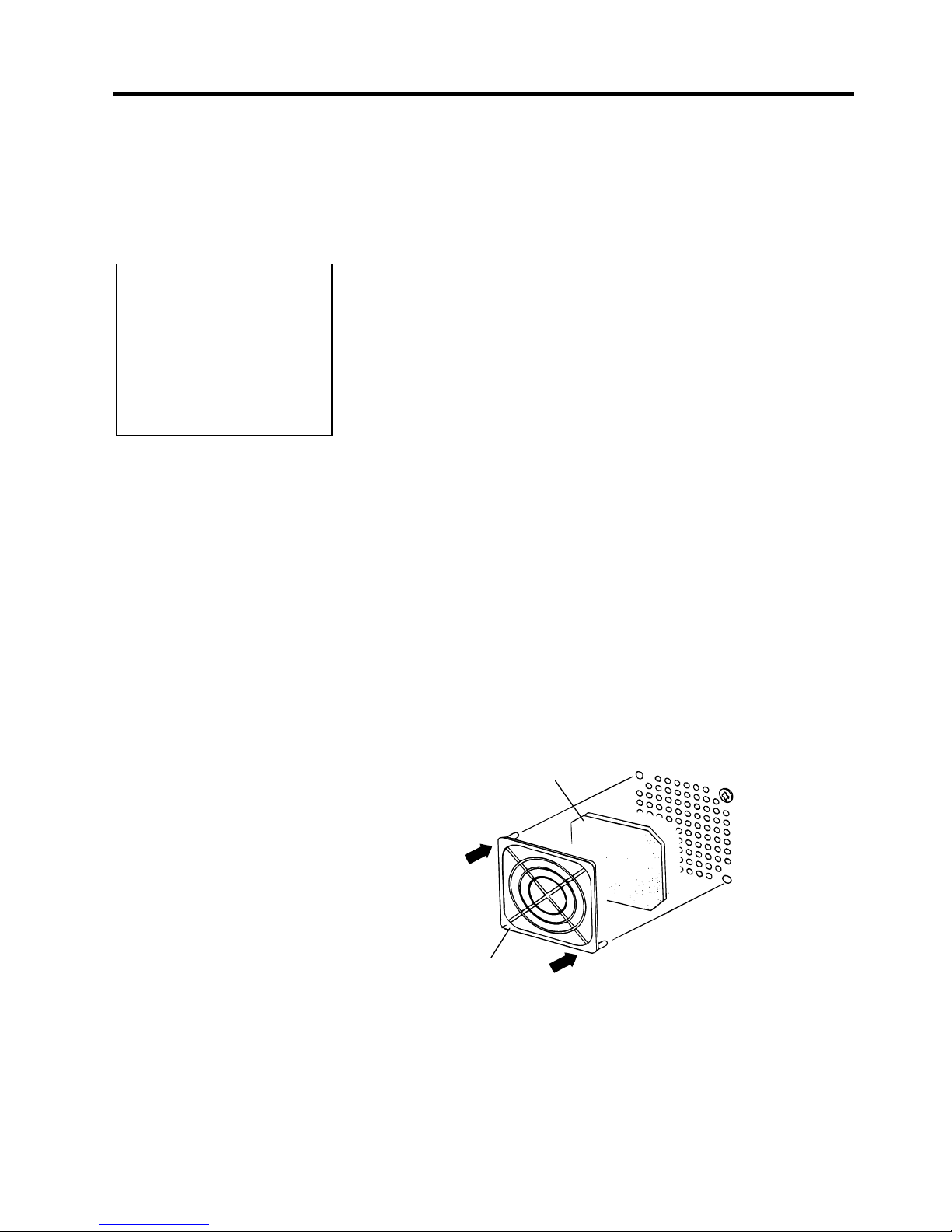
When installing the printer, it is important to ensure that the Fan Filter is
attached before using the printer.
The Fan Filter consists of 2 parts:
(1) Filter Pad
(2) Filter Retainer
To fit the Fan Filter, put the Filter Pad inside the Filter Retainer and
simply press into place as shown in the diagram below, ensuring
connecting pins are aligned with the connecting holes.
NOTE:
To communicate with the host
computer, one of the following
cables is required.
(1) RS-232C cable: 25 pins
(2) Centronics cable: 36 pins
(3) USB: B plug (Option)
(4) LAN: 10 Base-T or 100
Base-TX (Option)
Filter Pad
Filter Retainer
Snap On
Snap On
Page 15
2. PRINTER SETUP
ENGLISH VERSION EO1-33034
2.4 Connecting the Cables to Your Printer
E2- 3
2.4 Connecting the
Cables to Your
Printer
The following paragraphs outline how to connect the cables from the
printer to your host computer, and will also show how to make cable
connections to other devices. Depending on the application software
you use to print labels, there are 4 possibilities for connecting the
printer to your host computer. These are:
• A serial cable connection between the printer’s RS-232 serial
connector and one of your host computer’s COM ports.
(Refer to APPENDIX 3.)
• A parallel cable connection between the printer’s standard parallel
connector and your host computer’s parallel port (LPT).
• An Ethernet connection using the optional LAN board.
• A USB cable connection between the printer’s optional USB
connector and your host computer’s USB port. (Conforming to
USB 1.1)
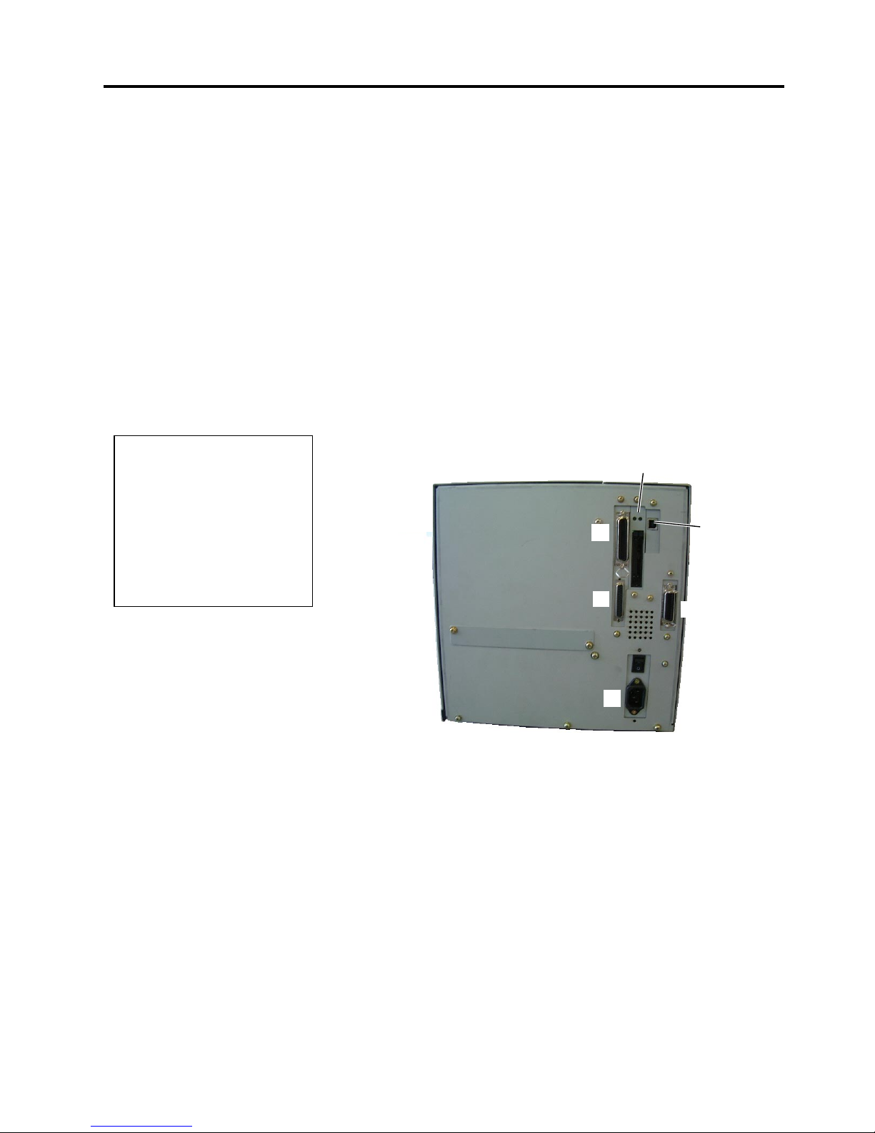
The diagram below shows all the possible cable connections to the
current version of the printer.
c Parallel Interface Connector (Centronics)
d Serial Interface Connector (RS-232C)
e Expansion I/O Interface Connector (Option)
f Power Inlet
g USB Interface Connector (Option)
h PCMCIA Card Slot (Option)
i LAN Interface Connector (Option)
c
d
e
f
g, h
,
or
i
NOTES:
1. The picture on the right shows
the layout of the interface
connectors when the options
are fully installed. It may be
different depending on your
system configuration.
2. The USB interface and LAN
interface cannot be used at the
same time.
gori
Page 16

2. PRINTER SETUP
ENGLISH VERSION EO1-33034
2.5 Connecting the Power Cord
E2- 4
2.5 Connecting the
Power Cord
1.
Make sure that the printer Power Switch is in the OFF (
{
{
) position.
2.
Connect the Power Cord to the printer as shown in the figure below.
3.
Plug the other end of the Power Cord into a grounded outlet as shown
in the figure below.
[QQ Type] [QP Type]
CAUTION!
1. Make sure that the printe
r
Power Switch is turned to
the OFF position (
{
)
before connecting the
Power Cord to prevent
possible electric shock or
damage to the printer.
2. Use only the Power Cord
supplied with the printer.
Use of any other cord
may cause electric shock
or fire.
3. Connect the Power Cord
to a supply outlet with a
properly grounded
(earthed) connection.
Power Cord
Power Cord
Power Cord
Power Switch
Page 17
2. PRINTER SETUP
ENGLISH VERSION EO1-33034
2.6 Turning the Printer ON/OFF
E2- 5
2.6 Turning the Printer
ON/OFF
2.6.1 Turning ON the Printer
2.6.2 Turning OFF the Printer
When the printer is connected to your host computer it is good practice to
turn the printer ON before turning on your host computer and turn OFF
your host computer before turning off the printer.
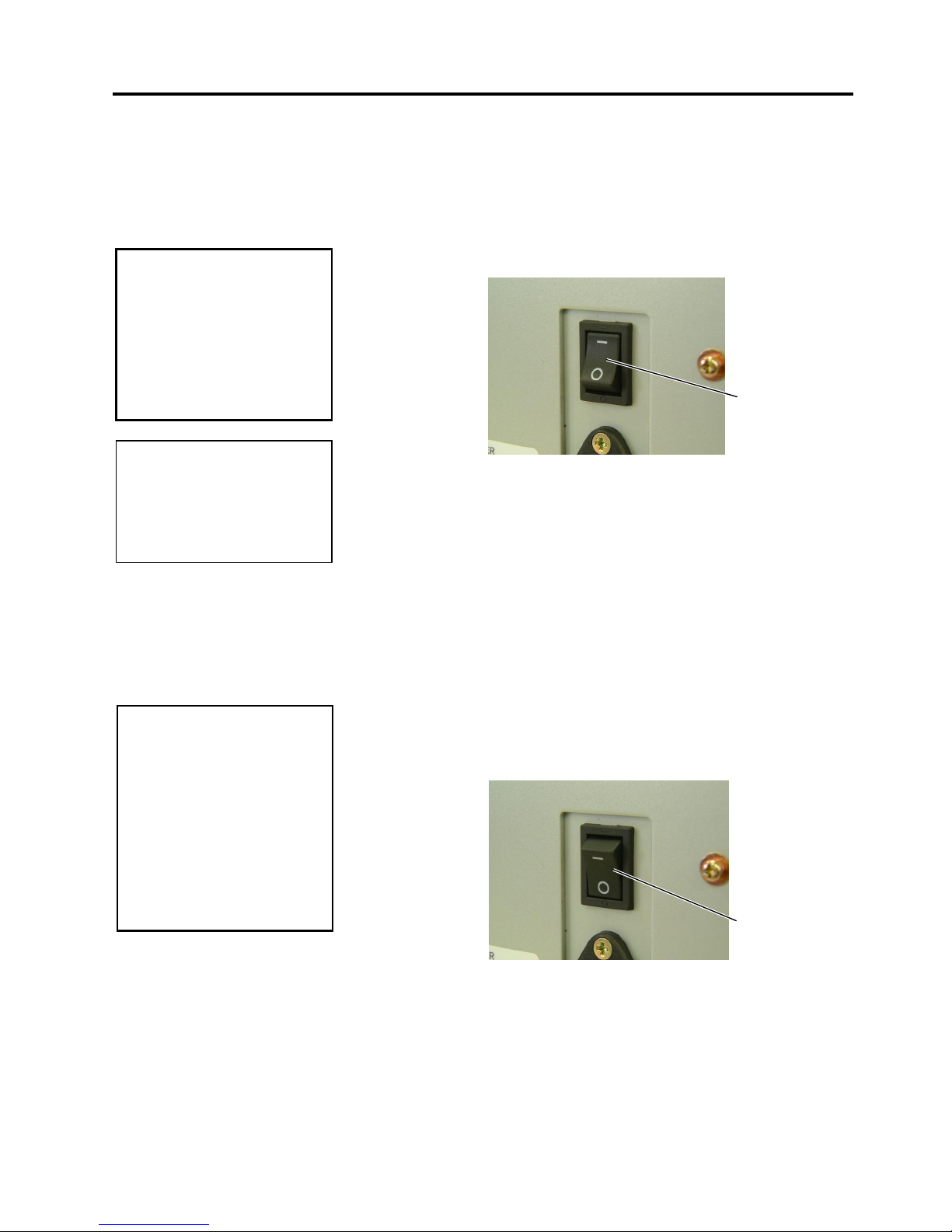
1.
To turn ON the printer power, press the Power Switch as shown in the
diagram below. Note that (
|
)
is the power ON side of the switch.
2.
Check that the ON LINE message appears in the LCD Message
Display and that the ON LINE and POWER LED lights are
illuminated.
1.
Before turning off the printer Power Switch verify that the ON LINE
message appears in the LCD Message Display and that the ON LINE
LED light is on and is not flashing.
2.
To turn OFF the printer power press the Power Switch as shown in the
diagram below. Note that ({)
is the power OFF side of the switch.
CAUTION!
Use the power switch to turn
the printer On/Off. Plugging
or unplugging the Power
Cord to turn the printer
On/Off may cause fire, an
electric shock, or damage to
the printer.
CAUTION!
1. Do not turn off the printer
power while the media is
being printed as this may
cause a paper jam or
damage to the printer.
2. Do not turn off the printer
power while the ON LINE
lamp is blinking as this
may cause damage to
your computer.
Power Switch
Power Switch
NOTE:
I
f a message other than ON
L
INE appears on the display or
the ERROR LED lamp is
illuminated, go to Section 5.1,
Error Messages.
Page 18
2. PRINTER SETUP
ENGLISH VERSION EO1-33034
2.7 Loading the Media
E2- 6
2.7 Loading the Media
The following procedure shows the steps to properly load the media into
the printer so that it feeds straight and true through the printer.
The printer prints both labels and tags.
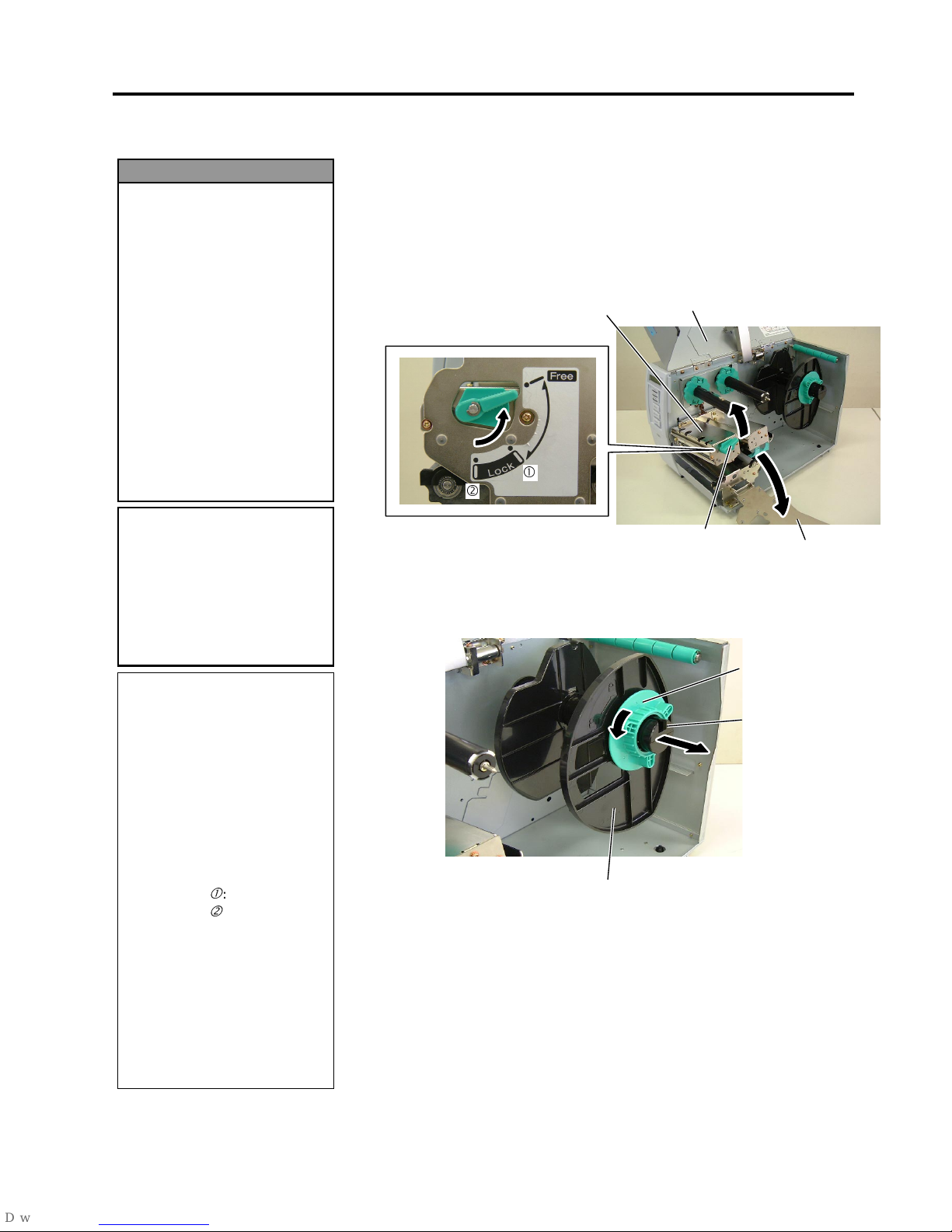
1.
Turn off the power and open the Top Cover.
2.
Turn the Head Lever to
Free
position, then release the Ribbon Shaft
Holder Plate.
3.
Open the Print Head Block.
4.
Turn the Locking Ring counterclockwise and remove the Supply
Holder from the Supply Shaft.
1. Do not touch any moving
parts. To reduce the risk
of fingers, jewellery,
clothing, etc., being
drawn into the moving
parts, be sure to load the
media once the printer
has stopped moving
completely.
2. The Print Head becomes
hot immediately after
printing. Allow it to cool
before loading the media.
3. To avoid injury, be careful
not to trap your fingers
while opening or closing
the cover.
WARNING!
NOTES:
1. When the Head Lever is
turned to
Free
position, the
Print Head is raised.
2. To allow printing the Head
Lever must be set to
Lock
position. (This ensures that
the Print Head is closed.)
There are two head pressure
levels in the
Lock
position.
Set the Head Lever depending
on the media type:
Position c: Labels
Position d: Tags
However, proper position
may differ depending on
media. For details, refer to
TOSHIBA TEC authorised
service representative.
3. Do not turn the Locking Ring
counter-clockwise too far or it
may come off the Supply
Holder.
CAUTION!
Be careful not to touch the
Print Head Element when
raising the Print Head Block.
Failure to do this may cause
missing dots by static
electricity or other print
q
uality problems.
Top Cover
Head Lever
Print Head Block
Locking Ring
Supply Holder
Supply Shaft
Ribbon Shaft
Holder Plate
c
d
Page 19
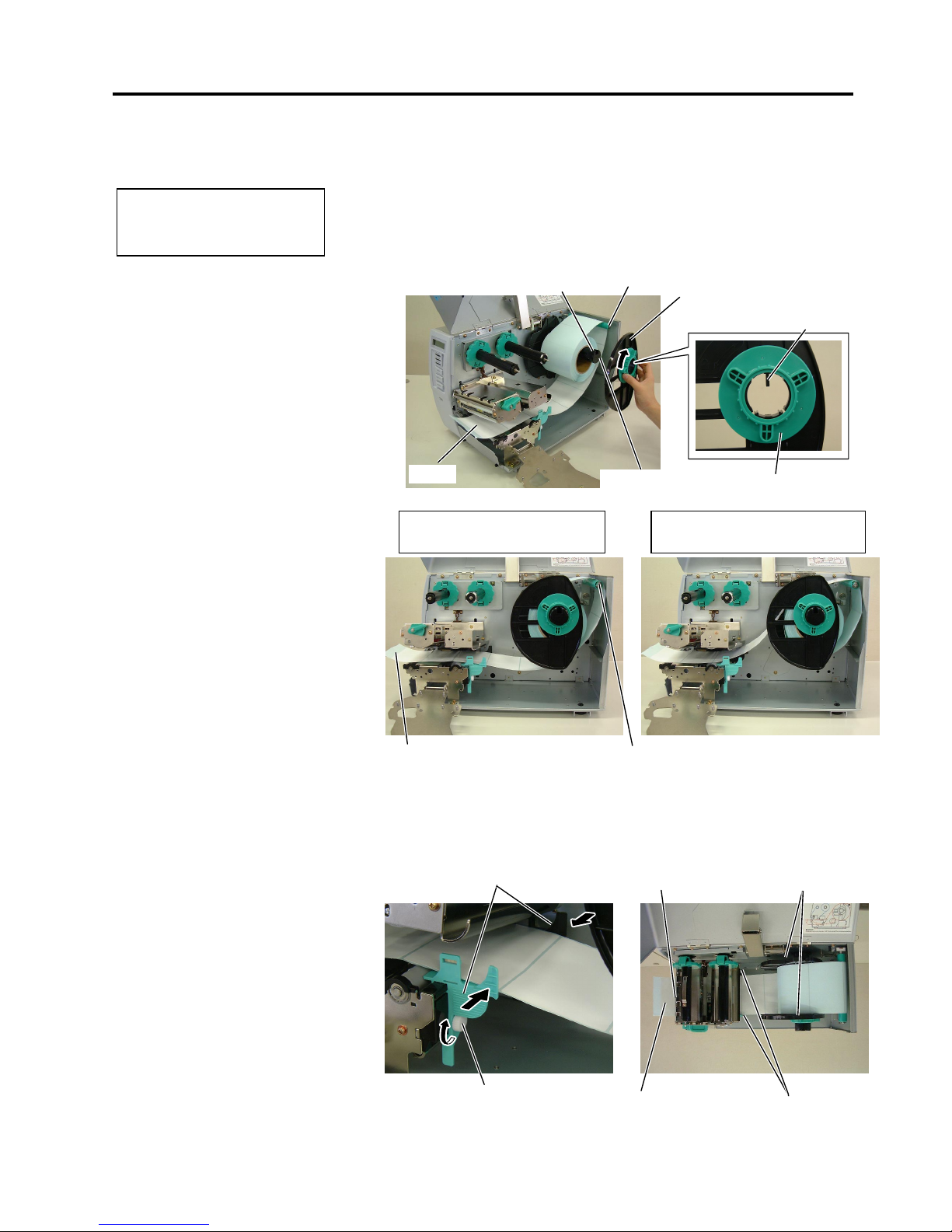
2. PRINTER SETUP
ENGLISH VERSION EO1-33034
2.7 Loading the Media
E2- 7
2.7 Loading the Media
(Cont.)
5.
Put the media on the Supply Shaft.
6.
Pass the media around the Damper, then pull the media towards the
front of the printer.
7.
Align the projection of the Supply Holder with the groove of the
Supply Shaft, and push the Supply Holder against the media until the
media is held firmly in place. This will center the media
automatically.
Then turn the Locking Ring clockwise to secure the Supply Holder.
8.
Place the media between the Media Guides, adjust the Media Guides
to the media width, and tighten the Locking Screw.
9.
Check that the media path through the printer is straight. The media
should be centered under the Print Head.
NOTE:
D
o not over-tighten the Locking
R
ing of the Supply Holder.
Supply Shaft
Suppl
y
Holder
Groove
Damper
Locking Ring
Projection
Media
Media Guide
Supply Holder
Media Guide
Print Head
Locking Screw
Media
Damper
Media
In case of a label rolled with
the print side facing inside.
In case of a label rolled with
the print side facing outside.
Page 20

2. PRINTER SETUP
ENGLISH VERSION EO1-33034
2.7 Loading the Media
E2- 8
2.7 Loading the Media
(Cont.)
10.
Lower the Print Head Block until it stops.
11.
After loading the media, it may be necessary to set the Media
Sensors used to detect the print start position for label or tag
printing.
Setting the Feed Gap Sensor position
(1) Remove the Locking Screw that secures the Media Sensor.
(2) Manually move the Media Sensor so that the Feed Gap Sensor is
positioned at the center of the labels. ( indicates the position of
the Feed Gap Sensor).
(3) Tighten the Locking Screw.
Setting the Black Mark Sensor position
(1) Remove the Locking Screw that secures the Media Sensor.
(2) Pull about 500 mm of media out of the front of the printer, turn the
media back on itself and feed it under the Print Head past the sensor
so that the black mark can be seen from above.
(3) Manually move the Media Sensor so that the Black Mark Sensor is
in line with the center of the black mark on the media. ( indicates
the position of the Black Mark Sensor).
(4) Tighten the Locking Screw.
NOTE:
B
e sure to set the black mark
sensor to detect the centre of the
black mark, otherwise a paper
j
am or no paper error may occur.
Locking Screw
Black Mark Sensor
Black Mark
Feed Gap Sensor
Label
Gap
Locking Screw
Media Sensor
Media Sensor
Page 21
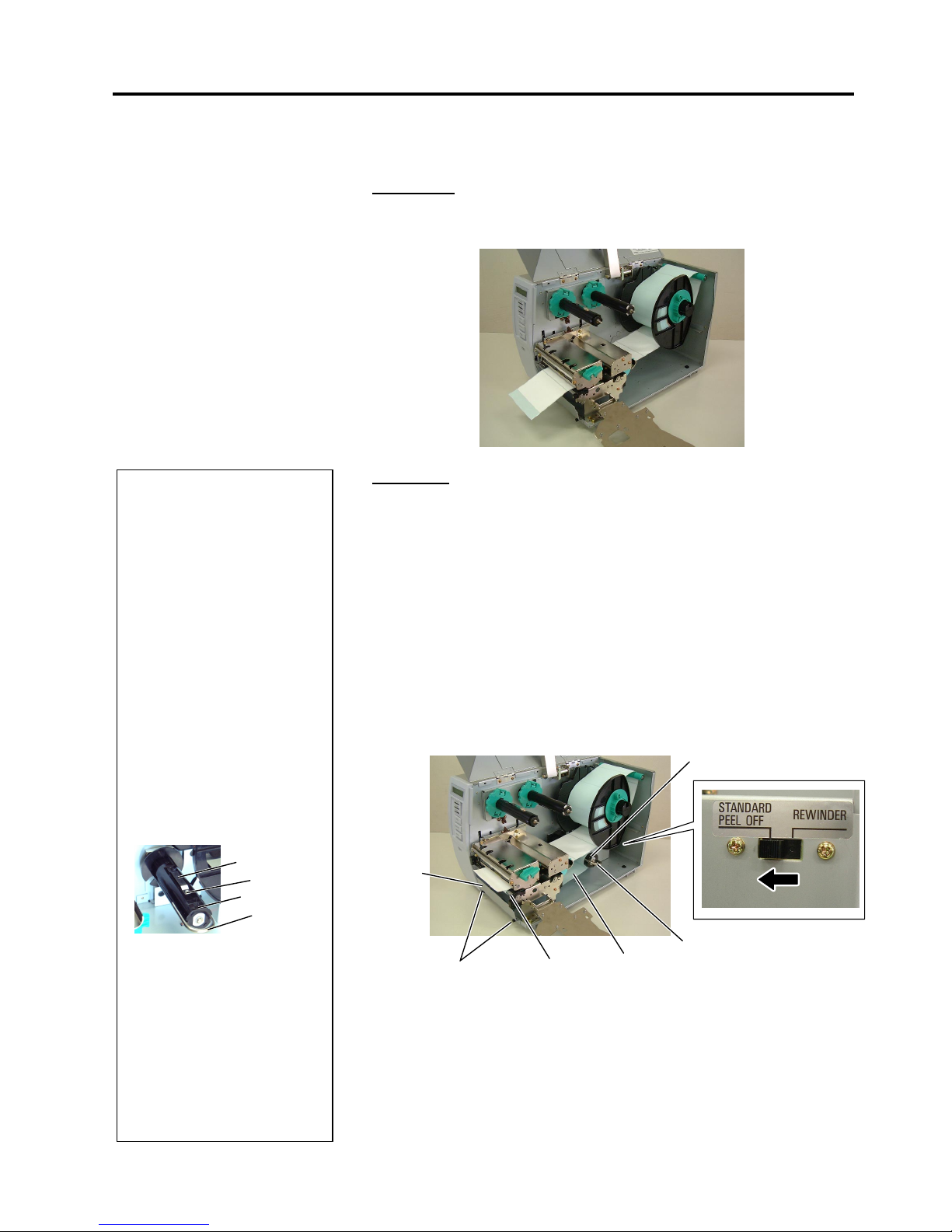
2. PRINTER SETUP
ENGLISH VERSION EO1-33034
2.7 Loading the Media
E2- 9
2.7 Loading the Media
(Cont.)
12.
There are four issue modes available on this printer. How to set the
media for each mode is provided below.
Batch mode
In the batch mode, the media is continuously printed and fed until the
number of labels/tags specified in the issue command have been printed.
Strip mode
When the optional Strip Module is fitted, the backing paper is
automatically removed from the label at the Strip Plate as each label is
printed.
(1) Remove enough labels from the leading edge of the media to leave
500mm of backing paper free.
(2) Insert the backing paper under the Strip Plate.
(3) Wind the backing paper onto the Take-up Spool and fix it in position
with the Take-up Clip. (Wind the paper counterclockwise around
the spool as this is the direction it rotates.)
(4) Rotate the Take-up Spool anti-clockwise a few times to remove any
slack in the backing paper.
(5) Set the Selection Switch mounted on the Rewinder Assembly to
STANDARD/PEEL OFF
position.
Take-up Clip
Take-up Spool
Front Plate
Black Screw
Backing Paper
NOTES:
1. Be sure to set the Selection
Switch to
STANDARD/
PEEL OFF
position.
2. The backing paper is easier
to feed back to the Take-Up
Spool if the Front Plate is
removed.
3. Fit the Take-Up Clip so that
the longer side of the clip is
fitted into the shallow groove
in the Take-Up Spool.
4. The backing paper can be
wound directly onto the Takeup Spool or a paper core.
When using the Take-up
Spool, detach the Holder
Stopper by removing the B3x4 screw. Otherwise, it may
be difficult to pull out the
wound backing paper roll.
Holder Stopper
B-3x4 Screw
Take-up Spool
Take-up Clip
When using a paper core, put
the core on the Take-up Spool
with the Holder Stopper on it,
and attach the top edge of the
backing paper to the core
with adhesive tape. The
Take-up Clip is not
necessary.
This winding method is
applicable to the Built-in
Rewinder mode.
Strip Plate
Page 22
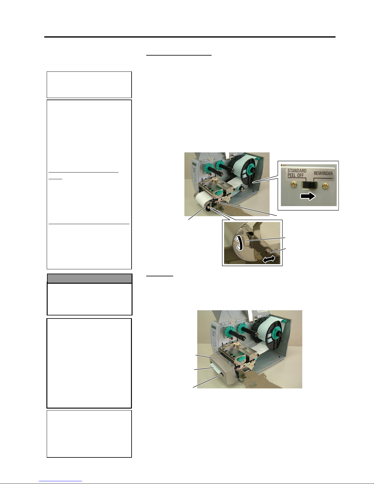
2. PRINTER SETUP
ENGLISH VERSION EO1-33034
2.7 Loading the Media
E2-10
2.7 Loading the Media
(Cont.)
Build-in rewinder mode
The Rewinder Assembly of the Strip Module can be used in batch mode
to take up the printed media as a Built-in Rewinder.
(1) Remove the two Black Screws to detach the Front Plate.
(2) Attach the Rewinder Guide Plate enclosed with the optional Strip
Module to the Strip Plate with the SMW-4x8 sems screws.
(3) Insert the media under the Rewinder Guide Plate.
(4) Wind the media onto the Take-up Spool and fix it in position with
the Take-up Clip.
(5) Rotate the Take-up Spool counterclockwise a few times to remove
any slack in the media.
(6) Set the Selection Switch mounted on the Rewinder Assembly to
REWINDER
position.
Cut mode
When the optional Cutter Module is fitted, the media is automatically cut.
A swing cutter and a rotary cutter are available as an option, but they are
used in the same way.
Insert the leading edge of the media into the Media Outlet of the Cutter
Module.
13.
If the loaded media is direct thermal media (a chemically treated
surface), the media loading procedure is now completed. Close the
Ribbon Shaft Holder Plate, and turn the Head Lever to
Lock
position to close. Then, close the Top Cover.
If the media is thermal transfer media, it is also necessary to load a
ribbon. Refer to Section 2.8 Loading the Ribbon.
CAUTION!
1. Be sure to cut the backing
paper of the label.
Cutting labels will cause
the glue to stick to the
cutter which may affect
the cutter quality and
shorten the cutter life.
2. Use of tag paper when
the thickness exceeds the
specified value may affect
the cutter life.
Media Outlet
Media
Cutter Module
NOTE:
B
e sure to set the Selection
Switch to REWINDER position.
ADJUSTMENT:
I
f the media skews when using
the Built-in Rewinder, turn the
A
djustment Knob of the
R
ewinder Guide Plate to correct
the media feed. Clockwise turn
moves the Rewinder Guide Plate
f
orward and counter-clockwise
moves it backward.
When the media skews to the
right:
L
oosen the SM-4x8 screw, turn
the Adjustment Knob clockwise,
and then tighten the SM-4x8
screw when the Rewinder Guide
Plate is positioned correctly.
When the media skews to the left:
L
oosen the SM-4x8 screw, turn
the Adjustment Knob counterclockwise, and tighten the SM4x8 screw when the Rewinder
Guide Plate is positioned
correctly.
Rewinder
Guide Plate
SM-4x8 Screw
SMW-4x8 Screw
Adjustment Knob
The cutter is sharp, so care
must be taken not to injure
y
ourself when handling the
cutter.
WARNING!
NOTE:
When using the Rotary Cutter, be
sure to install the Ribbon Saving
M
odule (B-9904-R-QM).
Failure to do this may cause a
p
aper jam or ribbon error.
Page 23
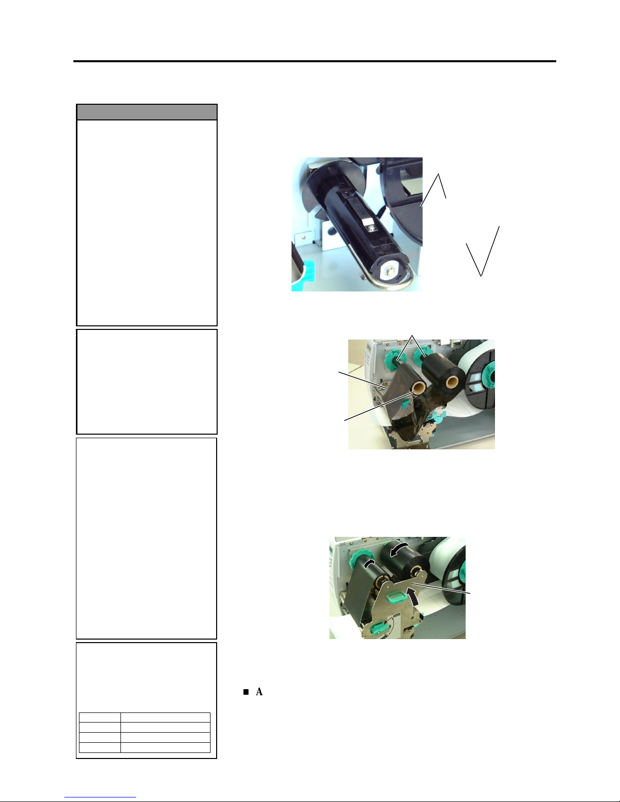
2. PRINTER SETUP
ENGLISH VERSION EO1-33034
2.8 Loading the Ribbon
E2-11
2.8 Loading the Ribbon
There are two types of media available for printing on: these are thermal
transfer media and direct thermal media (a chemically treated surface).
DO NOT LOAD a ribbon when using a direct thermal media.
1.
Grasp the tabs on the top and bottom of the Ribbon Stoppers and
move the Ribbon Stoppers back to the end of the Ribbon Shaft.
2.
Leaving plenty of slack between the ribbon spools, place the ribbon
onto the Ribbon Shafts as shown below.
3.
Slide the Ribbon Stoppers along the Ribbon Shafts to a position where
the ribbon is centred when fitted.
4.
Lower the Print Head Block and set the Ribbon Shaft Holder Plate
aligning its holes with the Ribbon Shafts.
5.
Take up any slack in the ribbon. Wind the leading tape onto the
ribbon take-up roll until the ink ribbon can be seen from the front of
the printer.
6.
Turn the Head Lever to
Lock
position to close the Print Head.
7.
Close the Top Cover.
Auto Ribbon Saving Mode
When the auto ribbon saving function is selected, it will be activated to
reduce ribbon loss when a no print area extends more than 20 mm (3 or 6
ips) or 30 mm (10 ips). For further information on this function, please
ask a TOSHIBA TEC authorised service representative.
CAUTION!
Be careful not touch the
Print Head Element when
raising the Print Head Block.
Failure to do this may cause
missing dots by static
electricity or other print
q
uality problems.
1. Do not touch any moving
parts. To reduce the risk
of fingers, jewellery,
clothing, etc., being
drawn into the moving
parts, be sure to load the
ribbon once the printer
has stopped moving
completely.
2. The print head becomes
hot immediately after
printing. Allow it to cool
before loading the ribbon.
3. To avoid injury, be carefu
l
not to trap your fingers
while opening or closing
the cover.
WARNING!
Ribbon Shaft
Ribbon Take-up Roll
Print Head Block
Ribbon Stopper
Ribbon Shaft
NOTES:
1. When attaching the ribbon
stoppers, make sure that the
pinchers face into the printer
2. Be sure to remove any slack in
the ribbon when printing.
Printing with a wrinkled
ribbon will lower the print
quality.
3. The Ribbon Sensor is mounted
on the rear of the Print Head
Block to detect a ribbon end.
When a ribbon end is
detected, “NO RIBBON”
message will appear on the
display and the ERROR LED
will illuminate.
NOTE:
Ribbon loss per ribbon saving
varies according to the relation
between the outer roll diameter
of the used ribbon and the print
speed.
Print speed Ribbon loss/Ribbon saving
3”/sec. Approx. 6 mm
6”/sec. Approx. 10 mm
10”/sec. Approx. 20 mm
Ribbon Shaft
Holder Plate
Page 24
2. PRINTER SETUP
ENGLISH VERSION EO1-33034
2.9 Inserting the Optional PCMCIA Cards
E2-12
2.9 Inserting the Optional
PCMCIA Cards
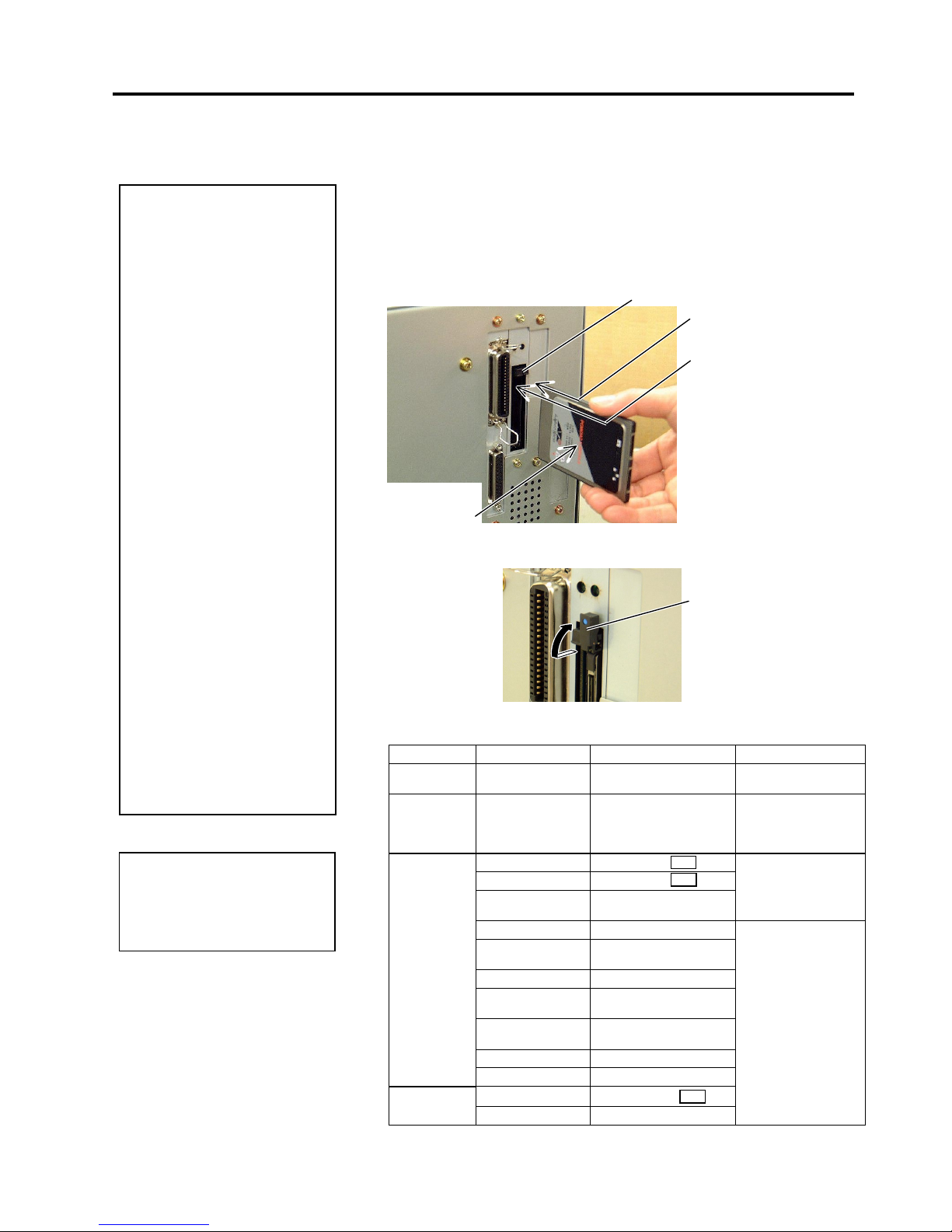
When the optional PCMCIA Interface Board is installed into the printer,
there will be two PCMCIA slots available as shown in the figure below.
This allows the use of Flash Memory type Cards or I/O Cards such as
LAN Cards. The following paragraphs outline how to insert PCMCIA
cards.
1.
Make sure that the printer’s Power Switch is in the OFF position.
2.
Hold the PCMCIA Card so that the side with the model name faces
left. Insert the card into the proper slot until the Eject Button pops
out.
3.
Slightly pull and fold the Eject Button upward.
4.
The following PCMCIA cards can be used.
Type Maker Description Remarks
ATA Card
San Disk,
Hitachi
A card conforming to the
PC card ATA standard
----------
LAN Card 3 COM 3CCE589ET Series
Install into the slot (2)
only. (This card
installed into the slot
(1) will not work.)
Maxell
EF-4M-TB
Maxell EF-4M-TB
Centennial
Technologies INC.
FL04M-15-11119-03
Read/Write
INTEL
IMC004FLSA
Simple
TECNOLOGY
STI-FL/4A
Mitsubishi
MF84M1-G7DAT01
PC Card KING
MAX
FJN-004M6C
Centennial
Technologies Inc.
FL04M-20-11138-67
PC Card
FJP-004M6R
Flash Memory
Card (4 MB)
Mitsubishi
MF84M1-GMCAV01
Maxell
EF-1M-TB
Flash Memory
Card (1 MB)
Mitsubishi
MF81M1-GBDAT01
Read (See NOTE.)
CAUTION!
1. To protect PC cards,
discharge static
electricity from your body
by touching the metal
cabinet of the printer
before touching the card.
2. Before inserting or
removing a PCMCIA
card make sure that the
printer’s power is turned
off.
3. Be sure to protect
PCMCIA Cards when not
in use by putting them
into their protective
covers.
4. Do not subject the card
to any shocks or
excessive force nor
expose the card to
extremes in temperature
or humidity.
5
. The card may be
inserted into the slot
halfway even in the
wrong orientation.
However, the slot is
safety designed so that
the card will not seat
against the connector
pins.
Slot 2:
(I/O type cards such as
LAN cards
)
Slot 1:
(Memory type cards only)
Eject Button
NOTE:
R
eading a read-only-type flash
memory is possible if it has been
used on the TOSHIBA TEC
p
rinter, such as B-472 and B-572.
CC
DC
AA
Model Name
Printed Side
Eject Button
Page 25

2. PRINTER SETUP
ENGLISH VERSION EO1-33034
2.10 Test Print
E2-13
2.10 Test Print
A print test should be performed to check that the printer is operating
correctly.
The following paragraphs guide you through the diagnostic procedure for
test label printing. Please follow the step-by-step procedures exactly for
best results.
1.
Use label stock for the test print. For best results, use labels that are
76 mm or longer in length.
2.
Press and hold the
[FEED]
and
[PAUSE]
keys while turning on the
printer power switch. The LCD Message Display will show the
following message.
3.
Press the
[FEED]
key three times to advance to the test print mode as
indicated by the following message in the LCD Message Display.
4.
Press the
[PAUSE]
key and the print condition setting display will
appear.
5.
Press the
[PAUSE]
key and the issue count setting display will
appear. Set the issue count with the
[FEED]
or
[RESTART]
key.
6.
Press the
[PAUSE]
key and the print speed setting display will
appear. Set the print speed with the
[FEED]
or
[RESTART]
key.
7.
Press the
[PAUSE]
key and the sensor type setting display will
appear. Select the sensor type with the
[FEED]
or
[RESTART]
key.
8.
Press the
[PAUSE]
key and the print mode setting display will
appear. Select the print mode with the
[FEED]
or
[RESTART]
key.
!',$* $
!7(67 35,17
!7(67 35,17
35,17 &21',7,21
!7(67 35,17
6(1625 75$16
!7(67 35,17
,668( &2817
!7(67 35,17
35,17 63((' ´V
NOTES:
1. Select the sensor type which
matches the media being used.
Basically, the Reflective
Sensor (Black Mark Sensor) is
for tag paper, and the
Transmissive Sensor (Feed
Gap Sensor) is for labels.
2. Select the print mode which
matches the media being used.
Basically, the thermal transfer
is with ribbon, and the
thermal direct is without
ribbon.
!7(67 35,17
357 7<3( 75$16)5
Page 26

2. PRINTER SETUP
ENGLISH VERSION EO1-33034
2.10 Test Print
E2-14
2.10 Test Print (Cont.)
9.
Press the
[PAUSE]
key and the issue mode setting display will
appear. Select the issue mode with the
[FEED]
or
[RESTART]
key.
10.
Press the
[PAUSE]
key and the media size setting display will
appear. Select the media size with the
[FEED]
or
[RESTART]
key.
11.
Press the
[PAUSE]
key and the paper feed setting display will
appear. Select whether or not a paper feed is performed with the
[FEED]
or
[RESTART]
key.
12.
When the
[PAUSE]
key is pressed, one blank media will be issued.
Then the LCD Message Display will return to showing the test print
start message.
13.
Press the
[PAUSE]
key and then
[FEED]
key. When pressing the
[PAUSE]
key, the printer will print the specified issue counts of the
slant lines (1 dot).
14.
Press the
[FEED]
key and
[PAUSE]
key, and the printer will print
the specified issue counts of the slant lines (3 dots).
15.
Press the
[FEED]
key and
[PAUSE]
key, and the printer will print
the specified issue counts of the characters of various sizes.
16.
Press the
[FEED]
key and
[PAUSE]
key, and the printer will print
the specified issue counts of the bar codes.
17.
Press the
[FEED]
key and
[PAUSE]
key, and the printer will print
the specified issue counts of blank labels.
18.
Press the
[PAUSE]
key and the LCD Message Display will return to
showing the test print start message.
!7(6735,17
7<3(>6@12&87
!7(6735,17
/$%(//(1PP
!7(6735,17
!7(6735,17
6/$17/,1('27
!7(6735,17
6/$17/,1('27
!7(6735,17
&+$5$&7(56
!7(6735,17
3$3(5)(('
!7(6735,17
%$5&2'(
NOTE:
When PAPER FEED is selected,
the printer feeds the media to the
correct print start position. If
the print start position
adjustment is unnecessary, select
PAPER NO FEED and save the
media.
NOTE:
I
f the
[FEED]
key is pressed after
the blank labels are printed, the
p
rinter will enter the Factory Test
mode. To exit from the Factory
Test mode, press the
[PAUSE]
key.
!7(6735,17
12135,17,1*
Page 27
2. PRINTER SETUP
ENGLISH VERSION EO1-33034
2.10 Test Print
E2-15
2.10 Test Print (Cont.)
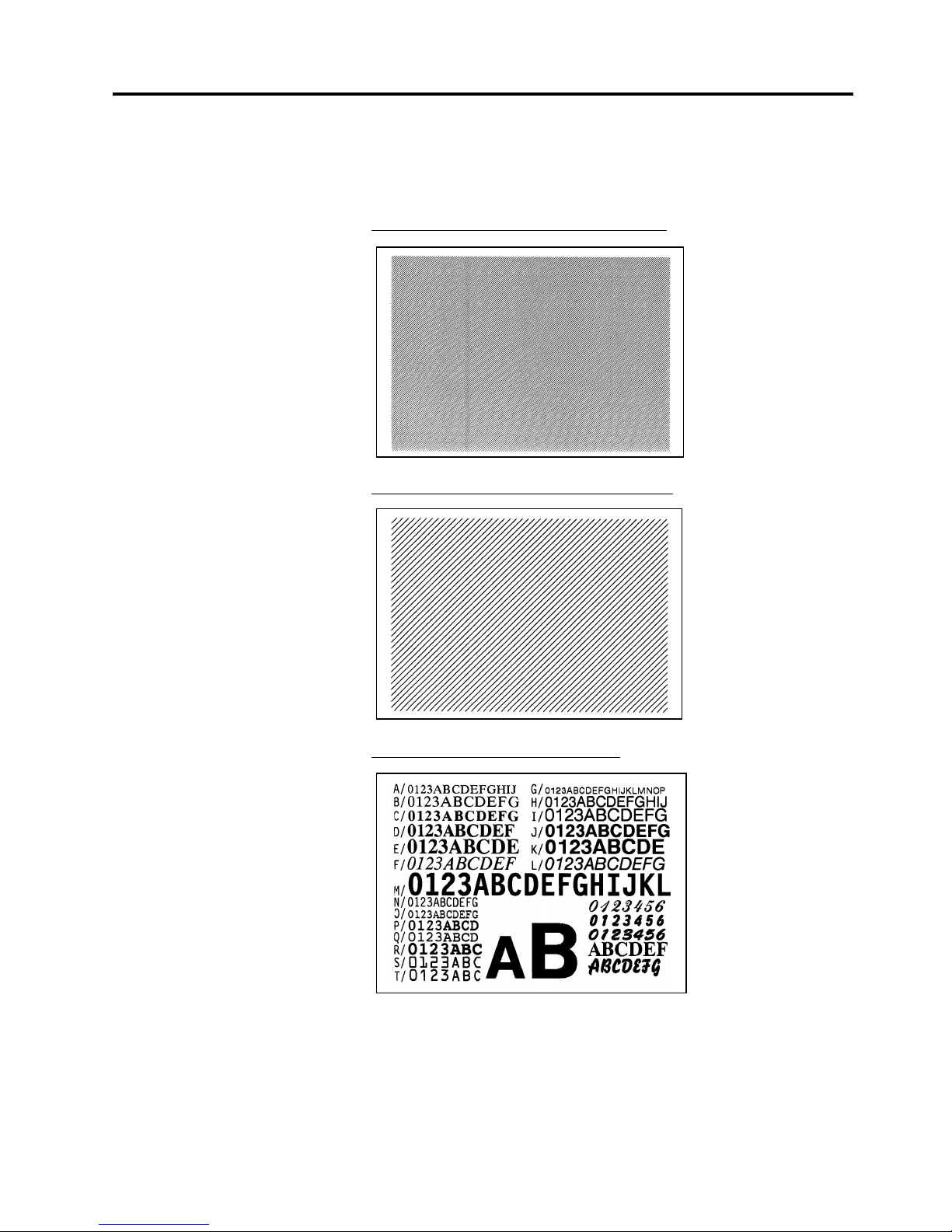
19.
When you have finished performing the test print operation, turn the
printer’s power OFF then back to ON and check that the LCD
Message Display shows ON LINE and that the ON LINE and
POWER LED lights are illuminated.
Sample of the slant line (1 dot) test print label
Sample of the slant line (3 dots) test print label
Sample of the character test print label
Page 28
2. PRINTER SETUP
ENGLISH VERSION EO1-33034
2.10 Test Print
E2-16
2.10 Test Print (Cont.)
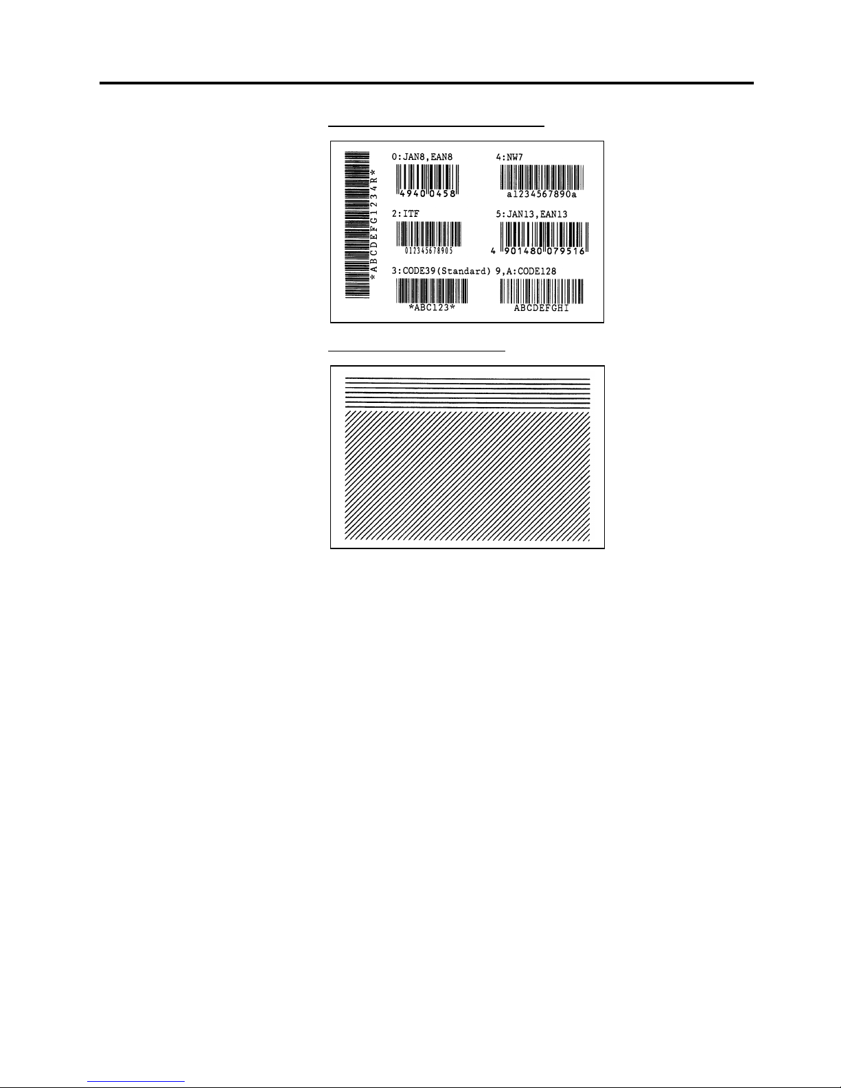
Sample of the bar code test print label
Sample of the factory test label
Page 29

3. ON LINE MODE
ENGLISH VERSION EO1-33034
3.1 Operation Panel
E3- 1
3. ON LINE MODE
3.1 Operation Panel
This chapter describes usage of the keys on the Operation Panel in On
Line mode.
When the printer is in On Line mode and connected to a host computer,
the normal operation of printing images on labels or tags can be
accomplished.
•
The figure below illustrates the operation panel and key functions.
The LCD Message Display shows messages in alphanumeric characters
and symbols to indicate the printer’s current status. Up to 32 characters
can be displayed on two lines.
There are three LED lights on the operation panel.
LED Illuminates when… Flashes when…
POWER
The printer is turned on. -----
ON LINE
The printer is ready to
print.
The printer is
communicating with
your computer.
ERROR
Any error occurs with
the printer.
The ribbon is nearly
over. (See NOTE.)
There are three keys on the operation panel.
PAUSE
Used to stop printing temporarily.
RESTART
Used to restart printing.
FEED
Used to feed the media.
NOTE:
Use the
[RESTART]
key to
resume printing after a pause, or
after clearing an error.
LCD Message Display
ON LINE LED (Green)
ERROR LED (Red)
[PAUSE]
key
POWER LED
(Green)
[FEED]
ke
y
[RESTART]
ke
y
NOTE:
Flashes only when the Ribbon
N
ear End Detection function is
selected.
Page 30

3. ON LINE MODE
ENGLISH VERSION EO1-33034
3.2 Operation
E3- 2
3.2 Operation
3.3 Reset
When the printer is turned on, the “ON LINE” message appears on the
LCD Message Display. It is shown during standby or normal printing.
1.
The printer is turned on, standing by, or printing.
2.
If any error occurs during printing, an error message appears. The
printer stops printing automatically. (The number on the right side
shows the remaining number of media to be printed.)
3.
To clear the error, press the
[RESTART]
key. The printer resumes
printing.
4
. If the
[PAUSE]
key is pressed during printing, the printer stops
printing temporarily. (The number on the right side shows the
remaining number of media to be printed.)
5.
When the
[RESTART]
key is pressed, the printer resumes printing.
A reset operation clears the print data sent from the computer to the
printer, and returns the printer to an idle condition.
1.
The printer is turned on, standing by, or printing.
2.
To stop printing, or clear the data sent from the computer, press the
[PAUSE]
key. The printer stops printing.
3.
Press and hold the
[RESTART]
key for 3 seconds or longer.
4.
Press the
[PAUSE]
key. The data sent from the computer will be
cleared, and the printer returns to an idle condition.
21/,1(
%6;79$
123$3(5
%6;79$
21/,1(
%6;79$
3$86(
%6;79$
21/,1(
%6;79$
NOTE:
I
f the
[RESTART]
key is held for
less than 3 seconds when the
p
rinter is in an error or pause
state, the printer restarts printing.
H
owever, when a communication
error or command error occurs,
the printer returns to an idle
condition.
21/,1(
%6;79$
3$86(
%6;79$
21/,1(
%6;79$
!5(6(7
Page 31

3. ON LINE MODE
ENGLISH VERSION EO1-33034
3.4 Dump Mode
E3- 3
3.4 Dump Mode
In Dump mode, any characters sent from the host computer will be
printed. Received characters are expressed in hexadecimal values. This
allows the user to verify programming commands and debug the
program.
For details, please refer to your nearest TOSHIBA TEC service
representative.
Page 32

4. MAINTENANCE
ENGLISH VERSION EO1-33034
4.1 Cleaning
E4- 1
4. MAINTENANCE
4.1 Cleaning
4.1.1 Print Head/Platen/
Sensors
This chapter describes how to perform routine maintenance.
To ensure the continuous high quality operation of the printer, you should
perform a regular maintenance routine. For high throughput it should be
done on a daily basis. For low throughput it should be done on a weekly
basis.
To maintain the printer performance and print quality, please clean the
printer regularly, or whenever the media or ribbon is replaced.
1.
Turn off the power and unplug the printer.
2.
Open the Top Cover.
3.
T urn the Head Lever to
Free
position, then release the Ribbon Shaft
Holder Plate.
4.
Open the Print Head Block.
5.
Remove the ribbon and media.
6.
Clean the Print Head Element with a Print Head Cleaner or a cotton
swab or soft cloth slightly moistened with alcohol.
7.
Wipe the Platen, Feed Roller, and Pinch Roller with a soft cloth
slightly moistened with alcohol. Remove dust or foreign substances
from the internal part of the printer.
8.
Wipe the Feed Gap Sensor and Black Mark Sensor with a dry soft
cloth.
WARNING!
1. Be sure to disconnect the
power cord before
performing maintenance.
Failure to do this may
cause an electric shock.
2. To avoid injury, be
careful not to pinch your
fingers while opening or
closing the cover and
print head block.
3. The print head becomes
hot immediately after
printing. Allow it to cool
before performing any
maintenance.
4. Do not pour water directly
onto the printer.
CAUTION!
1. Do not allow any hard
objects to touch the Print
Head or Platen, as this
may cause damage to
them.
2. Do not use any volatile
solvent including thinner
and benzene, as this
may cause discoloration
to the cover, print failure,
or breakdown of the
printer.
3. Do not touch the Print
Head Element with bare
hands, as static may
damage the Print Head.
4. Be sure to use the Print
Head Cleaner enclosed
with this printer. Failure
to do this may shorten
the Print Head life.
NOTE:
Please purchase the Print Head
Cleaner (P/No. 24089500013)
f
rom your authorised TOSHIBA
TEC service representative.
Print Head
Element
Print Head
Feed Roller
Platen
Pinch Roller
Black Mark Sensor/
Feed Gap Sensor
Page 33
4. MAINTENANCE
ENGLISH VERSION EO1-33034
4.1 Cleaning
E4- 2
4.1.2 Covers and Panels
4.1.3 Optional Cutter Module
Wipe the covers and panels with a dry soft cloth or a cloth slightly
moistened with mild detergent solution.
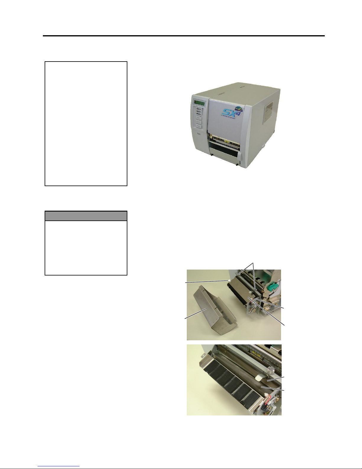
The swing cutter and rotary cutter are available as an option. They are
both cleaned in the same way. When removing the Cutter Cover of the
rotary cutter unit, remove the screws from the bottom of the cover.
1.
Loosen the two screws to remove the Cutter Cover.
2.
Remove the Plastic Head Screw to detach the Media Guide.
3.
Remove the jammed paper.
4.
Clean the Cutter with a soft cloth slightly moistened with alcohol.
5.
Reassemble the Cutter Module in the reverse order of removal.
CAUTION!
1. DO NOT POUR WATER
directly onto the printer.
2. DO NOT APPLY cleaner
or detergent directly onto
any cover or panel.
3. NEVER USE THINNER
OR OTHER VOLATILE
SOLVENT on the plastic
covers.
4. DO NOT clean the panel,
covers, or the supply
window with alcohol as it
may cause them t o
discolour, loose their
shape or develop
structural weakness.
WARNING!
1. Be sure to turn the power
off before cleaning the
Cutter Module.
2. As the cutter blade is
sharp, care should be
taken not to injure
yourself when cleaning.
Swing Cutter
Cutter Unit
Screw
Fixed Cutter
Cutter Cover
Plastic Head
Screw
Media Guide
Page 34

4. MAINTENANCE
ENGLISH VERSION EO1-33034
4.2 Care/Handling of the Media and Ribbon
E4- 3
4.2 Care/Handling of the
Media and Ribbon
• Do not store the media or ribbon for longer than the manufacturer’s
recommended shelf life.
• Store media rolls on the flat end. Do not store them on the curved
sides as this might flatten that side causing erratic media advance and
poor print quality.
• Store the media in plastic bags and always reseal after opening.
Unprotected media can get dirty and the extra abrasion from the dust
and dirt particles will shorten the print head life.
• Store the media and ribbon in a cool, dry place. Avoid areas where
they would be exposed to direct sunlight, high temperature, high
humidity, dust or gas.
• The thermal paper used for direct thermal printing must not have
specifications which exceed Na
+
800 ppm, K+ 250 ppm and Cl- 500
ppm.
• Some ink used on pre-printed media may contain ingredients which
shorten the print head’s product life. Do not use labels pre-printed
with ink which contain hard substances such as carbonic calcium
(CaCO
3
) and kaolin (Al2O3, 2SiO2, 2H2O).
For further information, please contact your local distributor or your
media and ribbon manufacturers.
CAUTION!
Be sure to carefully review
and understand the Supply
Manual. Use only media
and ribbons that meet
specified requirements. Use
of non-specified media and
ribbons may shorten the
head life and result in
problems with bar code
readability or print quality.
All media and ribbons
should be handled with care
to avoid any damage to the
media, ribbons or printer.
Read the guidelines in this
section carefully.
Page 35
5. TROUBLESHOOTING
ENGLISH VERSION EO1-33034
5.1 Error Messages
E5- 1
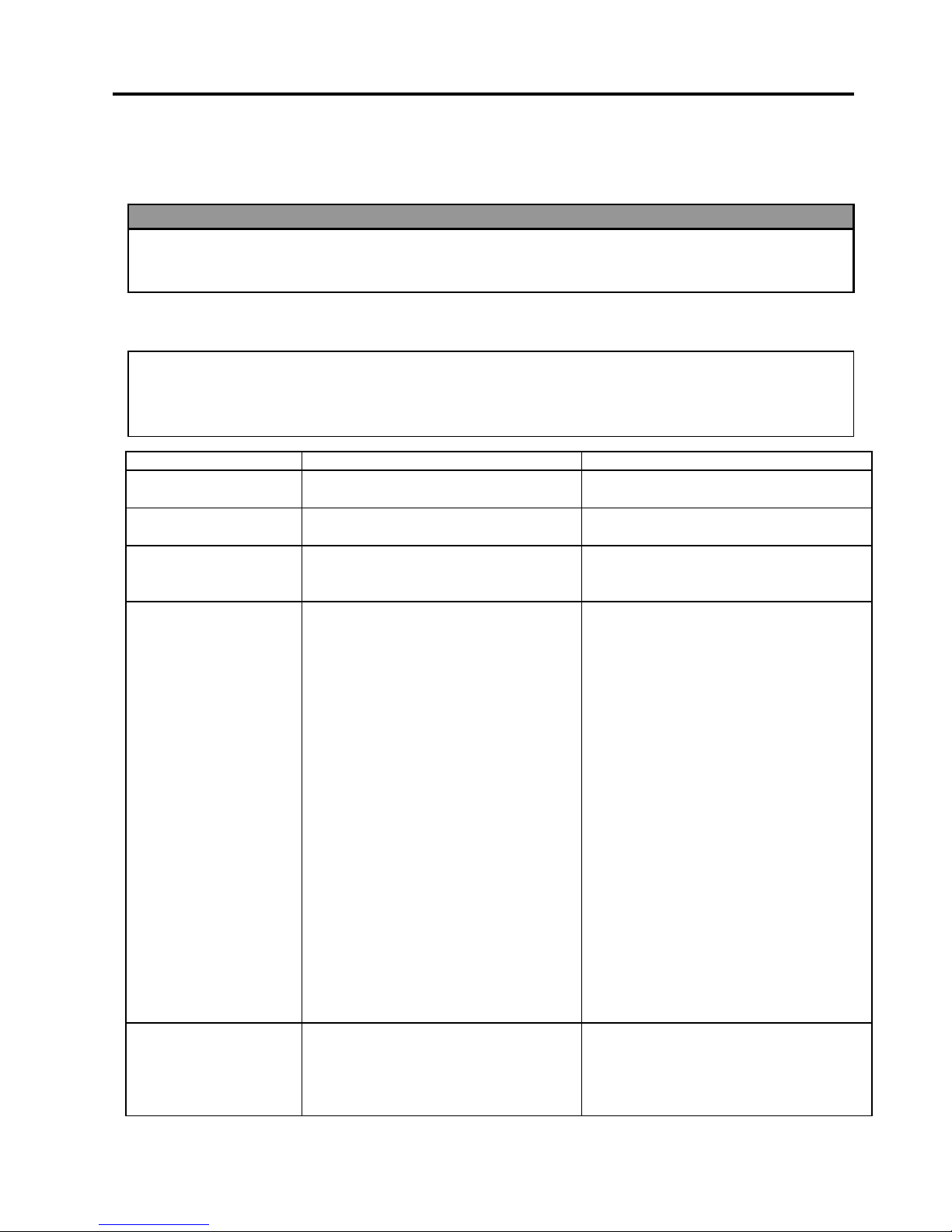
5. TROUBLESHOOTING
This chapter lists the error messages, possible problems, and their solutions.
5.1 Error Messages
Error Messages Problems/Causes Solutions
HEAD OPEN
The Print Head Block is opened in
Online mode.
Close the Print Head Block.
HEAD OPEN ****
Feeding or printing has been attempted
with the Print Head Block open.
Close the Print Head Block. Then press
the
[RESTART]
key.
COMMS ERROR
A communication error has occurred. Make sure the interface cable is correctly
connected to the printer and the host, and
the host is turned on.
PAPER JAM ****
1. The media is jammed in the media
path. The media is not fed smoothly.
2.
A wrong Media Sensor is selected for
the media being used.
3.
The Black Mark Sensor is not
correctly aligned with the Black
Mark on the media.
4.
Size of the loaded media is different
from the programmed size.
5.
The Feed Gap Sensor cannot
distinguish the print area from a label
gap.
1.
Remove the jammed media, and clean
the Platen. Then reload the media
correctly. Finally press the
[RESTART]
key.
2.
Turn the printer off and then on. Then
select the Media Sensor for the media
being used. Finally resend the print
job.
3.
Adjust the sensor position. Then press
the
[RESTART]
key.
4.
Replace the loaded media with one
that matches the programmed size
then press the
[RESTART]
key, or
turn the printer off and then on, select
a programmed size that matches the
loaded media. Finally resend the print
job.
5.
Refer to Section 5.4 to set the
threshold. If this does not solve the
problem, turn off the printer, and call a
TOSHIBA TEC authorised service
representative.
CUTTER ERROR ****
(Only when the cutter
module is installed on
the printer.)
The media is jammed in the cutter. Remove the jammed media. Then press
the
[RESTART]
key. If this does not
solve the problem, turn off the printer, and
call a TOSHIBA TEC authorised service
representative.
N
OTES:
•
If an error is not cleared by pressing the
[RESTART]
key, turn the printer off and then on.
•
After the printer is turned off, all print data in the printer is cleared.
•
“****”
indicates the number of unprinted media. Up to 9999 (in pieces).
WARNING!
If a problem cannot be solved by taking the actions described in t his chapt er , do not attempt to
repair the printer. Turn off and unplug the printer, then contact an authorised TOSHIBA TEC servic
e
representative for assistance.
Page 36
5. TROUBLESHOOTING
ENGLISH VERSION EO1-33034
5.2 Possible Problem s
E5- 2
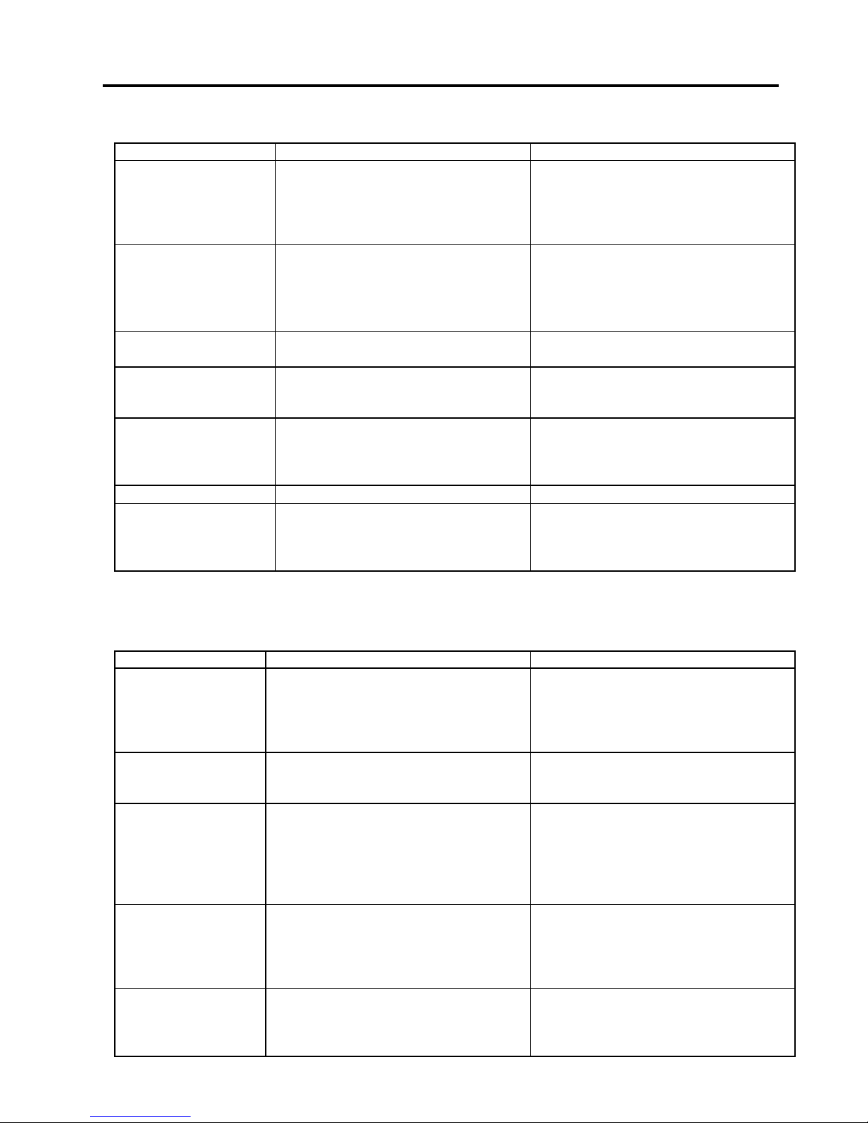
5.1 Error Messages (Cont.)
Error Messages Problems/Cause Solutions
NO PAPER ****
1. The media has run out.
2. The media is not loaded properly.
3. The media is slack.
1. Load new media. Then press the
[RESTART]
key.
2. Reload the media correctly. Then
press the
[RESTART]
key.
3. Take up any slack in the media.
RIBBON ERROR ****
The ribbon is not fed properly.
Remove the ribbon, and check the status
of the ribbon. Replace the ribbon, if
necessary. If the problem is not solved,
turn off the printer, and call a TOSHIBA
TEC authorised service representative.
NO RIBBON ****
The ribbon has run out. Load a new ribbon. Then press the
[RESTART]
key.
REWIND FULL ****
The Built-In Rewinder Unit is full. Remove the backing paper from the Built-
In Rewinder Unit. Then press the
[RESTART]
key.
EXCESS HEAD TEMP
The Print Head has overheated. Turn off the printer, and allow it to cool
down (about 3 minutes). If this does not
solve the problem, call a TOSHIBA TEC
authorised service representative.
HEAD ERROR
There is a problem with the Print Head. Replace the Print Head.
Other error messages A hardware or software problem may
have occurred.
Turn the printer off and then on. If this
does not solve the problem, turn off the
printer again, and call a TOSHIBA TEC
authorised service representative.
5.2 Possible Problems
This section describes problems that may occur when using the printer, and their causes and solutions.
Possible Problems Causes Solutions
The printer will not
turn on.
1. The Power Cord is disconnected.
2. The AC outlet is not functioning
correctly.
3. The fuse has blown, or the circuit
breaker has tripped.
1. Plug in the Power Cord.
2. Test with a power cord from another
electric appliance.
3. Check the fuse or breaker.
The media is not fed. 1. The media is not loaded properly.
2. The printer is in an error condition.
1. Load the media properly.
2. Solve the error in the message display.
(See Section 5.1 for more detail.)
Nothing is printed on
the media.
1. The media is not loaded properly.
2. The ribbon is not loaded properly.
3. The print head is not installed
properly.
4. The ribbon and media are not
matched.
1. Load the media properly.
2. Load the ribbon properly.
3. Install the print head properly. Close
the Print Head Block.
4. Select an appropriate ribbon for the
media type being used.
The printed image is
blurred.
1. The ribbon and media are not
matched.
2. The Print Head is not clean.
1. Select an appropriate ribbon for the
media type being used.
2. Clean the print head using the Print
Head Cleaner or a cotton swab slightly
moistened with ethyl alcohol.
The cutter does not
cut.
1. The Cutter Cover is not attached
properly.
2. The media is jammed in the Cutter.
3. The cutter blade is dirty.
1. Attach the Cutter Cover properly.
2. Remove the jammed paper.
3. Clean the cutter blade.
Page 37
5. TROUBLESHOOTING
ENGLISH VERSION EO1-33034
5.3 Removing Jamm ed Media
E5- 3
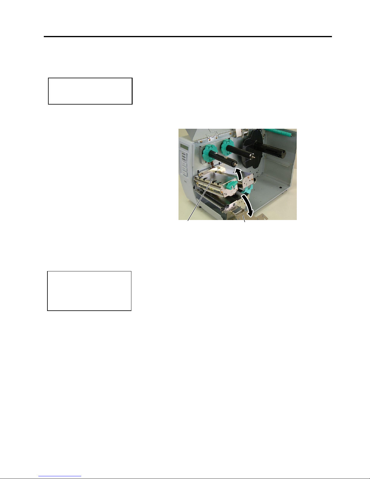
5.3 Removing Jammed
Media
This section describes in detail how to remove jammed media from the
printer.
1.
Turn off and unplug the printer.
2.
Open the Top Cover.
3.
Turn the Head Lever to
Free
position, then open the Ribbon Shaft
Holder Plate.
4.
Open the Print Head Block.
5.
Remove the ribbon and media.
6.
Remove the jammed media from the printer. DO NOT USE any sharp
implements or tools as these could damage the printer.
7.
Clean the Print Head and Platen, then remove any further dust or
foreign substances.
8.
Paper jams in the Cutter Unit can be caused by wear or residual glue
from label stock on the cutter. Do not use non-specified media in the
cutter.
CAUTION!
Do not use any tool that may
damage the Print Head.
NOTE:
I
f you get frequent jams in the
cutter, contact a TOSHIBA TEC
authorised service
representative.
Print Head Block
Ribbon Shaft Holder Plate
Page 38
5. TROUBLESHOOTING
ENGLISH VERSION EO1-33034
5.4 Threshold Setting
E5- 4
5.4 Threshold Setting
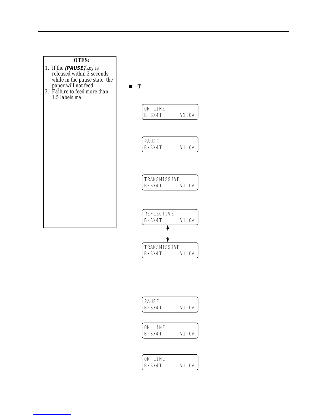
To maintain a constant print position the printer uses the Transmissive
Sensor to detect the gap between labels by measuring the amount of
light passing through the media. When the media is pre-printed, the
darker (or more dense) inks can interfere with this process causing
paper jam errors. To get around this problem a minimum threshold can
be set for the sensor in the following way.
Threshold setting procedure
1. Turn the power ON. The printer is in stand by mode.
2. Load a pre-printed media roll.
3. Press the [PAUSE] key.
4. The printer enters the pause mode.
5. Press and hold the [PAUSE] key for at least 3 seconds in the pause
state.
6. The sensor type is displayed.
7. Select the sensor to be adjusted by pressing the [FEED] key.
8. Press and hold the [PAUSE] key until more than 1.5 labels (tags)
have been issued.
The media will continue to be fed until the [PAUSE] key is
released. (Threshold setting for the selected sensor is completed by
this operation.)
9. Press the [RESTART] key.
10. The printer is in stand-by.
11. Send an issue command from the PC to the printer.
21 /,1(
%6;7 9$
3$86(
%6;7 9$
75$160,66,9(
%6;7 9$
5()/(&7,9(
%6;7 9$
75$160,66,9(
%6;7 9$
3$86(
%6;7 9$
21 /,1(
%6;7 9$
21 /,1(
%6;7 9$
NOTES:
1. If the
[PAUSE]
key is
released within 3 seconds
while in the pause state, the
paper will not feed.
2. Failure to feed more than
1.5 labels may result in an
incorrect threshold setting.
3. While the Print Head Block
is raised, the
[PAUSE]
key
does not work.
4. A paper end error cannot be
detected during paper feed.
5. Selecting the Transmissive
Sensor (for pre-printed
labels) within software
commands allows the
printer to detect the proper
print start position even
when using pre-printed
labels.
6. If using the Transmissive
Sensor and the printer
continues to print out of
position even after setting
the threshold, contact a
TOSHIBA TEC service
representative.
[FEED]
key
Black mark sensor
Feed gap sensor
Page 39
APPENDIX 1 SPECIFICATIONS
ENGLISH VERSION EO1-33034
A1.1 Printer
EA1- 1
APPENDIX 1 SPECIFICATIONS
Appendix 1 describes the printer specifications and supplies for use on the B-SX4T printer.
A1.1 Printer
The following is the printer specifications.
Model
Item
B-SX4T-GS10-QQ B-SX4T-GS10-QP
Supply voltage
Power consumption
During a print job
During standby
AC100 – 120V, 50/60 Hz±10%
1.6 A, 133 W maximum
0.18 A, 14 W maximum
AC220 – 240V, 50 Hz±10%
1.0 A, 134 W maximum
0.13 A, 14 W maximum
Operating temperature range
Relative humidity
Resolution
Printing method
Printing speed
Available media width (including
backing paper)
Effective print width (max.)
Issue mode
LCD Message display
Dimension (W × D × H)
Weight
Available bar code types
Available two-dimensional code
Available font
Rotations
Standard interface
5°C to 40°C (40°F to 104°F)
25% to 85% RH (no condensation)
8 dots/mm (203 dpi)
Thermal transfer or Thermal direct
76.2 mm/sec. (3 inches/sec.)
152.4 mm/sec (6 inches/sec.) For details, refer to Section A1.3.1.
254.0 mm/sec (10 inches/sec.)
30.0 mm to 112.0 mm (1.2 inches to 4.4 inches)
104.0 mm (4.1 inches)
Batch
Cut (Cut mode is enabled only when the optional Cutter Module is
installed.)
Strip (Strip mode is enabled only when the optional Strip Module is
installed.)
16 characters × 2 lines
291 mm × 460 mm × 308 mm (11.5” × 18.1” × 12.1”)
39.7 lb (18 kg) (Media and ribbon are not included.)
JAN8, JAN13, EAN8, EAN8+2 digits, EAN8+5 digits,
EAN13, EAN13+2 digits, EAN13+5 digits, UPC-E, UPC-E+2 digits,
UPC-E+5 digits, UPC-A, UPC-A+2 digits, UPC-A+5 digits, MSI,
ITF, NW-7, CODE39, CODE93, CODE128, EAN128, Industrial 2 to
5, Customer Bar Code, POSTNET, KIX CODE, RM4SCC (ROYAL
MAIL 4STATE CUSTOMER CODE), RSS14
Data Matrix, PDF417, QR code, Maxi Code, Micro PDF417, CP Code
Times Roman (6 sizes), Helvetica (6 sizes), Presentation (1 size),
Letter Gothic (1 size), Prestige Elite (2 sizes), Courier (2 sizes), OCR
(2 types), Gothic (1 size), Outline font (4 types), Price font (3 types)
0°, 90°, 180°, 270°
Serial interface (RS-232C)
Parallel interface (Centronics)
Optional interface PCMCIA interface (B-9700-PCM-QM)
USB interface (B-9700-USB-QM)
LAN interface (B-9700-LAN-QM)
Expansion I/O interface (B-7704-IO-QM)
N
OTES:
•
Data Matrix
TM
is a trademark of International Data Matrix Inc., U.S.
•
PDF417
TM
is a trademark of Symbol Technologies Inc., US.
•
QR Code is a trademark of DENSO CORPORATION.
•
Maxi Code is a trademark of United Parcel Service of America, Inc., U.S.
Page 40

APPENDIX 1 SPECIFICATIONS
ENGLISH VERSION EO1-33034
A1.2 Options
EA1- 2
A1.2 Options
Option Name Type Description
Swing cutter module B-4205-QM A stop and cut swing cutter.
Rotary cutter module B-8204-QM Rotary cutter
Strip module B-9904-H-QM This allows use of on-demand (peel-off) operation or to take-up
labels and backing paper together when using the rewind guide
plate. To purchase the strip module, please inquire at your local
distributor.
Ribbon saving
module
B-9904-R-QM This module moves the print head up and down by using a
solenoid to minimise ribbon usage as far as possible.
Expansion I/O
interface board
B-7704-IO-QM Installing this board in the printer allows connection to an
external device with the exclusive interface.
PCMCIA interface
board
B-9700-PCM-QM This board enables the use of the following PCMCIA cards.
LAN card:
3 COM 3CCE589ET (recommended)
ATA card: Conforming to PC card ATA standard
Flash memory card: 1MB and 4MB cards (See Section 2.9.)
Built-in LAN
interface board
B-9700-LAN-QM This board enables the printer to be used in a LAN network.
USB interface board B-9700-USB-QM Installing this board enables a connection to a PC which has a
USB interface.
A1.3 Media
Please make sure that the media being used is approved by TOSHIBA TEC. The warranty does not apply when a
problem is caused by using media that is not approved by TOSHIBA TEC.
For information regarding TOSHIBA TEC approved media, please contact a TOSHIBA TEC authorised service
representative.
A1.3.1 Media Type
Two types of media can be loaded for this thermal transfer and direct thermal printer: label or tag. The table
below shows size and shape of the media available for this printer.
N
OTE:
To purchase the optional kits, please contact the nearest authorised TOSHIBA TEC representative or TOSHIBA
TEC Head Quarters.
Label Tag paper
Cut position
Cut position
Stop
position
Stop
position
Feed Direction
Black Mark
(on reverse side)
Black Mark
(on reverse side) Refer to
NOTE 3 below.
h
e
c
e
g
h
c
d
i
i
k
k
f
j
Page 41

APPENDIX 1 SPECIFICATIONS
ENGLISH VERSION EO1-33034
A1.3 Media
EA1- 3
A1.3.1 Media Type (Cont.)
[Unit: mm]
Cut mode
Label dispensing mode
Item
Batch mode Strip mode
Rotary cutter
(*2)
Swing cutter
Label 10.0 – 1500.0 25.4 – 1500.0
3”/sec., 6”/sec.: 38.0 - 1500.0
38.0 – 1500.0
c
Media pitch
Tag 10.0 – 1500.0 ---- 3”/sec., 6”/sec.: 30.0 – 1500.0 25.4 – 1500.0
d
Media length 8.0 – 1498.0 23.4 – 1498.0
3”/sec., 6”/sec.: 25.0 – 1498.0
25.0 – 1498.0
(*1)
e
Width including backing paper
(
See NOTE 5
.)
30.0 – 112.0 50.0 – 112.0 30.0 – 112.0
f
Label width
(
See NOTE 5
.)
27.0 – 109.0 47.0 – 109.0 27.0 – 109.0
g
Gap length 2.0 – 20.0 6.0 – 20.0
h
Black mark length (Tag paper) 2.0 – 10.0
i
Effective print width 10.0 – 104.0±0.2
Label 6.0 – 1496.0 21.4 – 1496.0
3”/sec., 6”/sec.: 23.0 - 1496.0
23.0 – 1496.0
j
Effective print length
Tag 8.0 – 1498.0
----
3”/sec., 6”/sec.: 28.0 – 1498.0
23.0 – 1498.0
k
Print speed up/slow down area 1.0
Label 0.13 – 0.17
Thickness
Tag 0.15 – 0.29
Maximum effective length for on the fly issue 1361.0
Maximum outer roll diameter Ø200
Roll direction Inside
Inner core diameter Ø76.2±0.3
A1.3.2 Detection Area of the Transmissive Sensor
The Transmissive Sensor is movable from the centre to the left edge of media.
The Transmissive Sensor detects a gap between labels, as illustrated below.
<Label>
N
OTES:
1. To ensure print quality and print head life use only TOSHIBA TEC specified media.
2. The media length specifications for use of the cutter are:
*1: When issuing a label using the swing cutter, label length should be 35.0 mm – (Gap length/2).
*2: The rotary cutter does not support the print speed of 10”/sec.
When using the Rotary Cutter, be sure to install the Ribbon Saving Module (B-9904-R-QM). Failure to do
this may cause a paper jam or ribbon error.
3. When marking black marks on the label rolls, they should be marked at the gaps.
4. “On the fly issue” means that the printer can feed and print without stopping between labels.
5. There are restrictions in use of the media which is narrower than 50 mm. For details, refer to TOSHIBA TEC
service re
p
resentative.
Sensor position
Area to be detected.
Centre of media
Print side
Min. 12 mm
Label
Gap
Label
Min. 2.0 mm
(Min. 6.0 mm when using
the cutter module.)
Sensor is movable
within this range.
Media feed direction
Page 42

APPENDIX 1 SPECIFICATIONS
ENGLISH VERSION EO1-33034
A1.3 Media
EA1- 4
A1.3.2 Detection Area of the Transmissive Sensor (Cont.)
<Tag paper with square holes>
A1.3.3 Detection Area of the Reflective Sensor
The Reflective Sensor is movable from the centre to the left edge of media.
The reflection factor of the Black Mark must be 10% or lower with a waveform length of 950 nm.
The Reflective Sensor should be aligned with the centre of the Black Mark.
A1.3.4 Effective Print Area
The figure below illustrates the relation between the head effective print width and media width.
Sensor should be positioned at
the centre of the black mark.
Centre of media
Min. 12 mm
Media feed direction
Min. 2.0 mm
Sensor is movable
within this range.
4 mm
112 mm (Max. media width)
104 mm±0.2
(Head Effective Print Range)
Out of print range
Out of print range
4 mm
Detecting the black
marks on the back.
Sensor position
Centre of media
Min. 12 mm
Media feed direction
Min. 2.0 mm
Sensor is movable
within this range.
Square holes
(Round holes are not acceptable.)
Print side
N
OTE:
R
ound holes are not acceptable.
Page 43
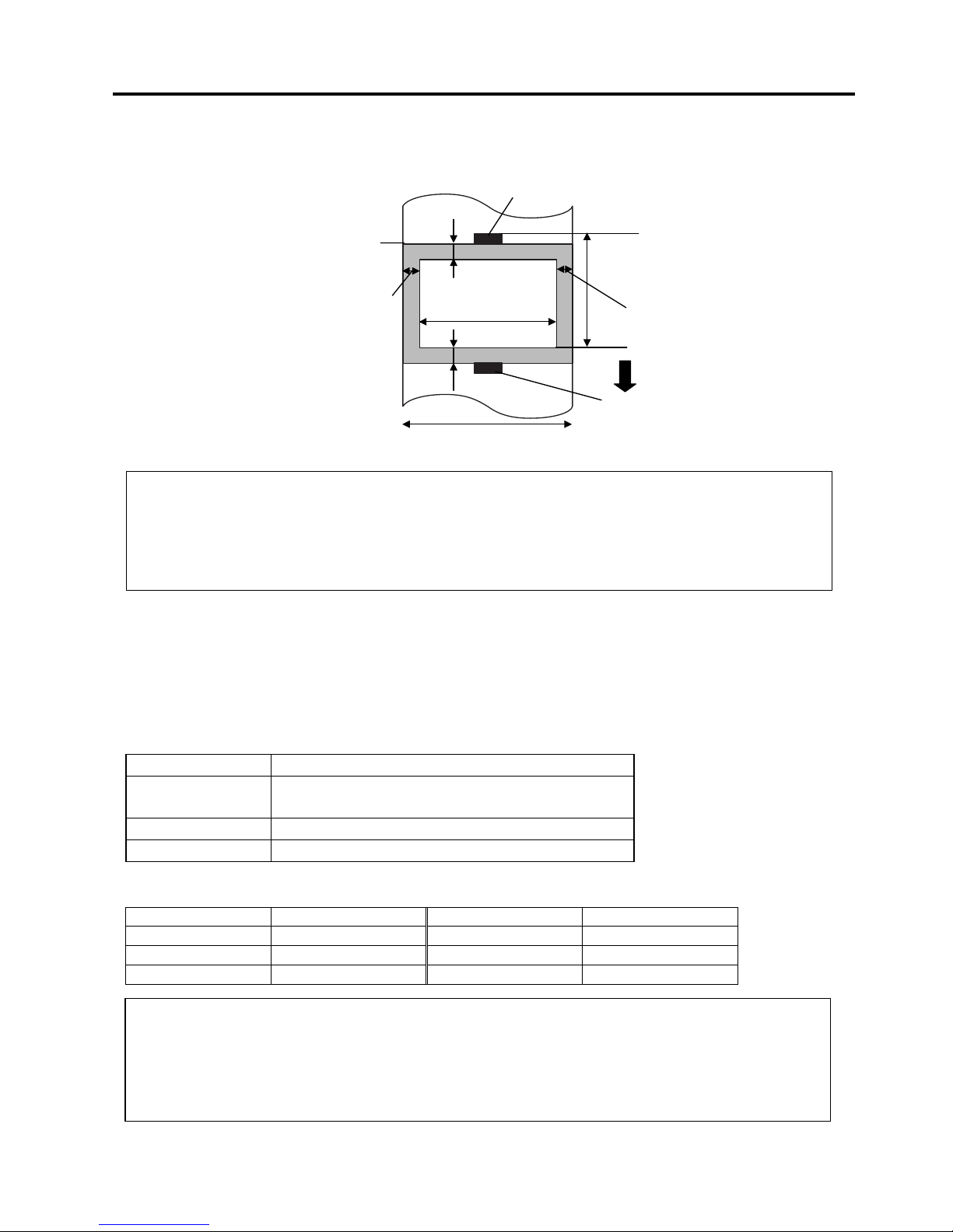
APPENDIX 1 SPECIFICATIONS
ENGLISH VERSION EO1-33034
A1.4 Ribbon
EA1- 5
A1.3.4 Effective Print Area (Cont.)
The figure below shows the effective print area on the media.
A1.4 Ribbon
Please make sure that the ribbon being used is approved by TOSHIBA TEC. The warranty does not apply to any
problem caused by using non-approved ribbons.
For information regarding TOSHIBA TEC approved ribbon, please contact a TOSHIBA TEC service
representative.
Type Spool type
Width 41 – 112 mm
Recommended width is 41, 50, 68, 84, and 112 mm.
Length 600 m
Outside Diameter φ90 mm (max.)
The table below shows the correlation between ribbon width and media width (backing paper is not included.)
Ribbon width Media width Ribbon width Media width
41 mm 30 – 36 mm 84 mm 63 – 79 mm
50 mm 36 – 45 mm 112 mm 71 – 112 mm
68 mm 45 – 63 mm
N
OTES:
1. Be sure not to print on the 1.5-mm wide area from the media edges (shaded area in the above figure).
Printing this area may cause ribbon wrinkles, resulting in a poor print quality of the guaranteed print area.
2. The centre of media is positioned at the centre of the Print Head.
3. Print quality in the 3-mm area from the print head stop position (including 1-mm non-printable area for print
speed slow down) is not guaranteed.
N
OTES:
1. To ensure print quality and print head life use only TOSHIBA TEC specified ribbons.
2. To avoid ribbon wrinkles use a ribbon that is wider than the media by 5 mm or more. However, too much
difference in width between the two may cause wrinkles.
3. You can use a ribbon that is narrower than the media by 5 mm or more, however, this makes the print area
narrower.
Start line
Area to be detected.
Area to be detected.
Media feed direction
1.5 mm from the
left edge of media
Media width
(backing paper width is not included.)
Media height
10 – 1500 mm
1.5 mm from the
right edge of media
1mm
1mm
Guaranteed print area
Page 44

APPENDIX 2 MESSAGES AND LEDS
ENGLISH VERSION EO1-33034
APPENDIX 2 MESSAGES AND LEDS
EA2- 1
APPENDIX 2 MESSAGES AND LEDS
Appendix 2 describes the LCD messages displayed on the operation panel.
Symbols in the message
1: : The LED is illuminated. ~: The LED is flashing. z: The LED is unlit.
2: ****: the number of unprinted media. Up to 9999 (in pieces)
3: %%%%%%%: ATA Card’s remaining memory 0 to 9999999 (in K bytes)
4: ###: Flash memory card remaining memory for PC save area: 0 to 895 (in K bytes)
5: &&&&: Remaining flash memory capacity for storing writable characters 0 to 3147 (in K bytes)
LED Indication
No.
LCD Message
POWER ONLINE ERROR
Printer Status
Restoration by
RESTART ke
y
Yes/No
Acceptance of
Status Request
Reset Command
Yes/No
ON LINE
z
In online mode ----- Yes
1
ON LINE
~ z
In online mode (The printer in
communication)
----- Yes
2
HEAD OPEN
z z
The print head block is opened in online
mode.
----- Yes
3
PAUSE ****
z z
The printer is paused. Yes Yes
4
COMMS ERROR
z
A parity, overrun, or framing error has
occurred during communication through
the RS-232C.
Yes Yes
5
PAPER JAM ****
z
The media is jammed during paper feed. Yes Yes
6
CUTTER ERROR****
z
A problem has occurred with the cutter
module.
Yes Yes
7
NO PAPER ****
z
The media has run out, or the media is
not loaded properly.
Yes Yes
8
NO RIBBON ****
z
The ribbon has run out. Yes Yes
9
HEAD OPEN ****
z
Feed or printing was attempted with the
print head block open.
Yes Yes
10
HEAD ERROR
z
There is a problem with the print head. Yes Yes
11
EXCESS HEAD TEMP
z
The print head is overheated. No Yes
12
RIBBON ERROR****
z
The ribbon has been torn. A problem
has occurred with the sensor that
determines the torque for the ribbon
motor.
Yes Yes
13
REWIND FULL ****
z
An overflow error has occurred in the
rewinder unit.
Yes Yes
14
SAVING%%%%%%%
or
SAVING ###&&&&
z
In writable character or PC command
save mode
----- Yes
15
FLASH WRITE ERR.
z
An error has occurred while writing to
flash memory or ATA card.
No Yes
16
FORMAT ERROR
z
An erase error has occurred in
formatting the flash memory or ATA
card.
No Yes
17
FLASH CARD FULL
z
Data cannot be stored because the flash
memory or ATA card is full.
No Yes
18
Display of error
message (See Notes.)
z
A command error has occurred in
analyzing the command.
Yes Yes
19
POWER FAILURE
z A power failure has occurred. No No
20
INTIALIZING…
z z A flash memory card is being initialised. ----- -----
21
100BASE LAN
INITIALIZING…
z z
100 Base LAN Board is being
initialized.
----- -----
Page 45
APPENDIX 2 MESSAGES AND LEDS
ENGLISH VERSION EO1-33034
APPENDIX 2 MESSAGES AND LEDS
EA2- 2
N
OTES:
• If a command error is found in the command received, 16 bytes of the command error, starting from the command
code, will be displayed. (However, [LF] and [NUL] will not be displayed.)
Example 1
[ESC] T20 G
30 [LF] [NUL]
Command error
The following message appears.
Example 2
[ESC] XR; 0200, 0300, 0450, 1200, 1
, [LF] [NUL]
Command error
The following message appears.
Example 3
[ESC] PC001; 0A
00, 0300, 2, 2, A, 00, B [LF] [NUL]
Command error
The following message appears.
• When the error command is shown, “? (3FH)” appears for codes other than codes 20H to 7FH and A0H to DFH.
7*
%6;79$
;5
%6;79$
3&$
%6;79$
Page 46

APPENDIX 3 INTERFACE
ENGLISH VERSION EO1-33034
APPENDIX 3 INTERFACE
EA3-1
APPENDIX 3 INTERFACE
Interface Cables
To prevent radiation and reception of electrical noise, the interface cables must meet the following requirements:
• Fully shielded and fitted with metal or metallised connector housings.
• Keep as short as possible.
• Should not be bundled tightly with power cords.
• Should not be tied to power line conduits.
RS-232C Cable description
The serial data cable used to connect the printer to the host compute should be one of the following two types:
N
OTE:
Use an RS-232C cable with the connector including inch type securing screws for the QQ model or metric type
securing screws for the QP model.
DB-9S
Connector to PC
Pin No. Signal
1 N.C.
2 RXD
3 TXD
4 DTR
5 GND
6 DSR
7 RTS
8 CTS
9 N.C.
Housing Shield
DB-25P
Connector to Printer
Pin No. Signal
1 F.G.
2 RXD
3 TXD
4 CTS
5 RTS
6 DTR
7 SG
20 DSR
DB-25S
Connector to PC
Pin No. Signal
1 Shield
2 TXD
3 RXD
4 RTS
5 CTS
6 DSR
7 GND
20 DTR
DB-25P
Connector to Printer
Pin No. Signal
1 F.G.
2 RXD
3 TXD
4 CTS
5 RTS
6 DTR
7 SG
20 DSR
Page 47
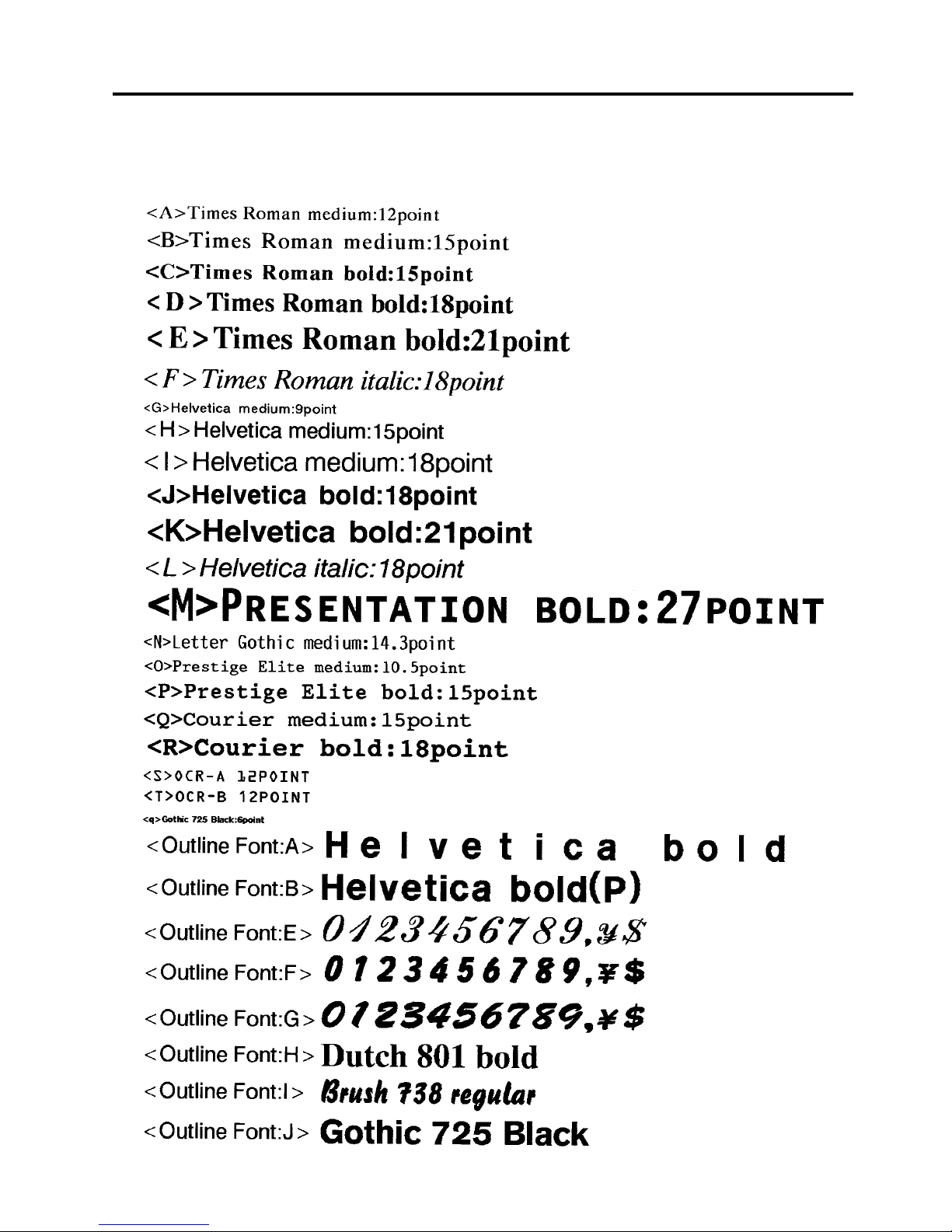
APPENDIX 4 PRINT SAMPLES
ENGLISH VERSION EO1-33034
APPENDIX 4 PRINT SAMPLES
EA4-1
APPENDIX 4 PRINT SAMPLES
Font
Page 48
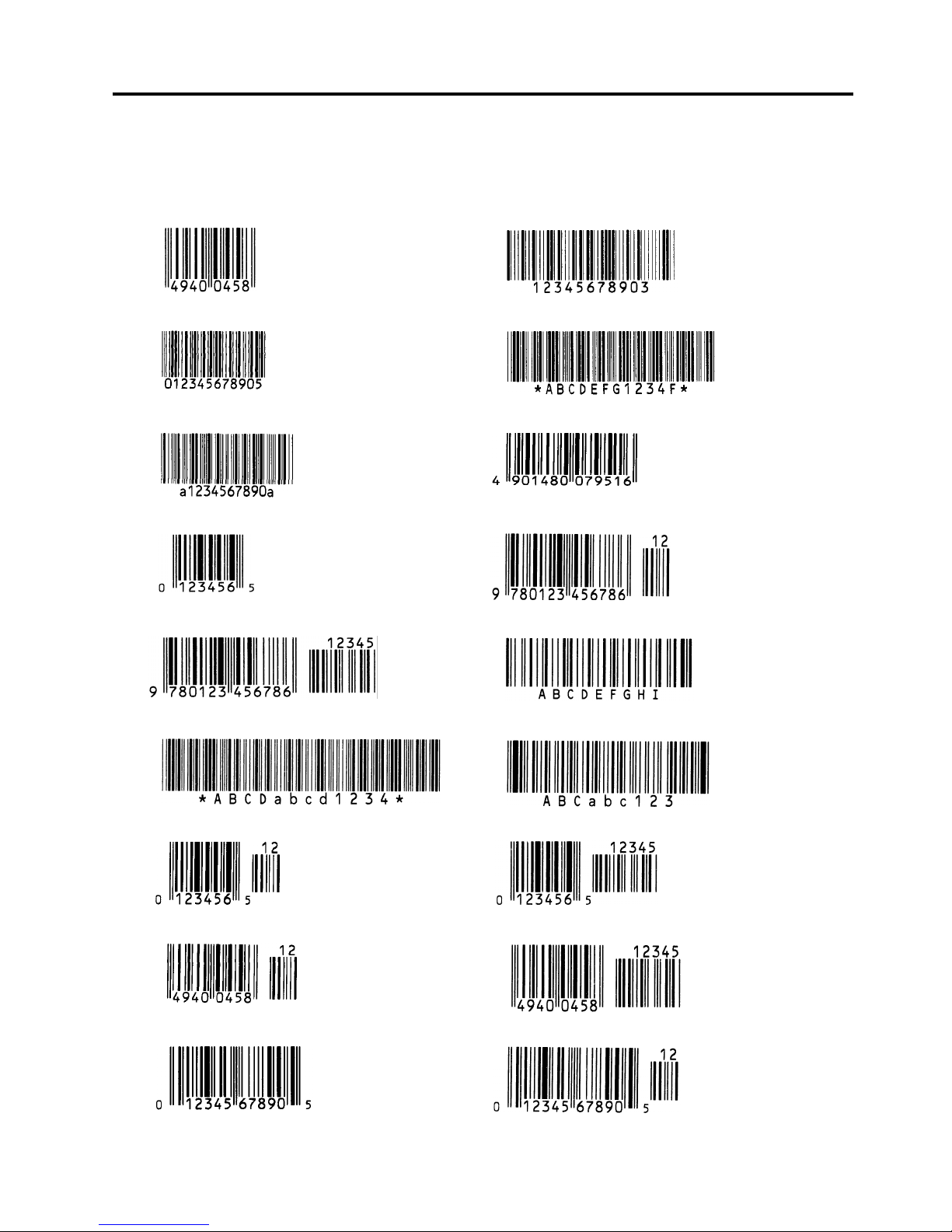
APPENDIX 4 PRINT SAMPLES
ENGLISH VERSION EO1-33034
APPENDIX 4 PRINT SAMPLES
EA4-2
APPENDIX 4 PRINT SAMPLES (Cont.)
Bar codes
JAN8, EAN8 MSI
Interleaved 2 of 5 CODE39 (Standard)
NW7 JAN13, EAN13
UPC-E EAN13+2 digits
EAN13+5 digits CODE128
CODE39 (Full ASCII) CODE93
UPC-E+2 digits UPC-E+5 digits
EAN8+2 digits EAN8+5 digits
UPC-A UPC-A+2 digits
Page 49

APPENDIX 4 PRINT SAMPLES
ENGLISH VERSION EO1-33034
APPENDIX 4 PRINT SAMPLES
EA4-3
APPENDIX 4 PRINT SAMPLES (Cont.)
UPC-A+5 digits UCC/EAN128
Industrial 2 of 5 POSTNET
Customer bar code Customer bar code of high priority
KIX Code RM4SCC
RSS-14 RSS-14 Stacked
RSS-14 Stacked Omnidirectional RSS Limited
RSS Expanded
Data Matrix PDF417
QR code Micro PDF417
MaxiCode CP Code
Page 50

GLOSSARIES
ENGLISH VERSION EO1-33034
GLOSSARIES
GLOSSARIES
Bar code
A code which represents alphanumeric characters
by using a series of black and white stripes in
different widths. Bar codes are used in various
industrial fields: Manufacturing, Hospitals,
Libraries, Retail, Transportation, Warehousing, etc.
Reading bar codes is a fast and accurate means of
capturing data while keyboard entry tends to be
slow and inaccurate.
Batch mode
Issue mode that continuously prints media until the
specified number of media has been printed.
Black mark
A mark printed on the media so that the printer can
maintain a constant print position by detecting this
mark.
Black mark sensor
A reflective sensor which detects the difference of
potential between the black mark and print area to
find the print start position.
Built-in rewinder mode
Printer mode of operation where an optional strip
module is installed to take up printed media onto
the build-in rewinder.
Cut mode
Printer mode of operation where an optional cutter
module is installed to automatically cut media from
the supply roll after they are printed. The print
command can specify to cut every media or to cut
after a set number of media have been printed.
Cutter module
A device used to cut the media.
DPI
Dot Per Inch
The unit used to express print density.
Expansion I/O interface
An optional interface circuit that may be installed
into printer to allow the printer to be connected to
an external device such as a wrapping machine and
to receive feed, print start, and pause signals from
the external device and to send back print, pause,
and error status signals to the external device.
Feed gap sensor
A transmissive sensor which detects the difference
of potential between the gap between labels and
the label to find the print position of the label.
Font
A complete set of alphanumeric characters in one
style of type. E.g. Helvetica, Courier, Times
Gap
Clearance between labels
IPS
Inch per second
The unit used to express print speed.
Label
A type of media with adhesive backing.
LCD
Liquid Crystal Display
Installed on the operation panel and displays
operation modes, error message and so on.
Media
Material on which data is printed by the printer.
Label, tag paper, fanfold paper, perforated paper,
etc.
PCMCIA interface
An optional interface circuit that may be installed
into the printer to allow the use of the small credit
card sized PC cards such as flash memory cards
and LAN cards. PCMCIA is the acronym for
Personal Computer Memory Card International
Association.
Page 51

GLOSSARIES
ENGLISH VERSION EO1-33034
GLOSSARIES
Pre-printed media
A type of media on which characters, logos, and
other designs have been already printed.
Print head element
The thermal print head consists of a single line of
tiny resistive elements and when current is allowed
to flow through each element it heats up causing a
small dot to be burned onto thermal paper or a
small dot of ink to be transferred from a thermal
ribbon to ordinary paper.
Print speed
The speed at which printing occurs. This speed is
expressed in units of ips (inches per second).
Reflective sensor
See Black mark sensor.
Resolution
The degree of detail to which an image can be
duplicated. The minimum unit of divided image is
called a pixel. As the resolution becomes higher,
the number of pixels increased, resulting in more
detailed image
Ribbon
An inked film used to transfer an image onto the
media. In the thermal transfer printing, it is heated
by the thermal print head, causing an image to be
transferred onto the media
Strip mode
A device used to remove labels from the backing
paper.
Supply
Media and ribbon
Tag
A type of media with no adhesive. Usually tags
are made of cardboard or other durable material.
Thermal direct printing
A printing method using no ribbon, but thermal
media which reacts to heat. The thermal print head
heats the thermal media directly, causing print
image to be printed on the media.
Thermal print head
A print head using thermal transfer or thermal
direct printing method.
Thermal transfer printing
A printing method that the thermal print head heats
an ink or resin coating on the ribbon against the
media, causing the ink/resin to transfer onto the
media.
Threshold setting
A sensor setting operation to have the printer
maintain a constant print position of pre-printed
media.
Transmissive sensor
See Feed gap sensor.
USB (Universal Serial Bus)
An interface that is used to connect peripherals,
such as a printer, keyboard, mouse. The USB
allows disconnection of a USB device without
turning off the power.
Page 52

INDEX
ENGLISH VERSION EO1-33034
INDEX
INDEX
A
Auto ribbon saving 2-11
B
Backing paper A1-3
Bar code A1-1
Batch mode 2-9
Black mark 2-8, A1-2, A1-4
Black mark length A1-3
Black mark sensor 2-8, 4-1
Built-in rewinder 2-10
C
Centronics 1-3, 2-3
Cut mode 2-10
Cutter module 2-10, 4-2, A1-2
D
Dimensions 1-3
E
Effective Print length A1-3
Effective print width A1-3
ERROR LED 1-4, 3-1
Error message 5-1
Expansion I/O interface 1-3, 2-3
Expansion I/O interface board A1-2
F
Fan filter 2-2
Feed gap sensor 2-8, 4-1
FEED key 1-4, 3-1
Flash memory card 2-12
G
Gap 2-8, A1-3
Gap length A1-3
Guaranteed print area A1-5
H
Head lever 1-4, 2-6
I
Interface 2-3, A1-1, A3-1
Issue mode 2-9, A1-1
J
Jammed media 5-3
L
Label 2-6, A1-2, A1-3
LCD message display 1-3, 1-4, 3-1
M
Media 2-6, 4-3, A1-2
Media length A1-3
Media pitch A1-3
Media sensor 2-8
O
ON LINE LED 1-4, 3-1
Operation Panel 1-3, 1-4, 3-1
P
Parallel interface 1-3
Parallel port 2-3
PAUSE key 1-4, 3-1
PCMCIA card 2-12
PCMCIA interface board 2-12, A1-2
Platen 1-4, 4-1
Power consumption A1-1
Power cord 1-2, 2-4
POWER LED 1-4, 3-1
Power switch 1-3, 2-4, 2-5
Pre-printed media 4-3, 5-4
Print head 1-4, 4-1
Print head block 1-4
Printing method A1-1
Printing speed A1-1
R
Reflective sensor 2-13, A1-4
Resolution A1-1
RESTART key 1-4, 3-1
Ribbon 2-11, 4-3, A1-5
Ribbon shaft 1-4, 2-11
Ribbon stopper 1-4, 2-11
Ribbon width A1-5
Rotation A1-1
RS-232C 1-3, 2-3, A3-1
Page 53

INDEX
ENGLISH VERSION EO1-33034
INDEX
S
Serial interface 1-3
Strip mode 2-9
Strip module 2-9, A1-2
Supply voltage A1-1
T
Tag A1-2
Test print 2-13
Thermal direct 2-13, A1-1
Thermal transfer 2-13, A1-1
Threshold setting 5-4
Transmissive sensor 2-13, A1-3
Two-dimensional code A1-1
U
USB interface 1-3, 2-3, A1-2
W
Weight A1-1
Page 54

Page 55

EO30-33015
1
This supplement is applicable to the following Owner’s Manuals:
• B-SX4T Series (EO1-33034)
• B-SX5T Series (EO1-33036)
Precautions for using the Ribbon Saving Function
The ribbon saving module is standard on the B-SX5T series, but not on the B-SX4T series. Also, the
ribbon saving function has been set to off by the parameter setting when the printer is delivered.
Therefore, to use the ribbon saving function on the B-SX4T series, it is necessary to install the
B-9904-R-QM optional ribbon saving module and to enable the ribbon saving function by the parameter
setting.
Regarding the B-SX5T series, you only need to enable the ribbon saving function by the parameter
setting.
When enabling the ribbon saving function, it must be set depending on the head lever position. For
details, please contact the nearest TOSHIBA TEC service representative or sales agent.
Printer model and option Head lever position Parameter setting Ribbon saving function
B-SX5T-TS12-QQ
B-SX5T-TS12-QP
B-SX4T-TS10-QQ
B-SX4T-TS10-QP
Position •: Label
or
Position ‚: Tag
RBN SAVE OFF
(Default)
Disabled
Position •: Label RBN SAVE ON(Label) Enabled for label B-SX5T-TS12-QQ
B-SX5T-TS12-QP
B-SX4T-TS10-QQ + B-9904-R-QM
B-SX4T-TS10-QP + B-9904-R-QM
Position ‚: Tag RBN SAVE ON(TAG) Enabled for tag paper
NOTES:
1. Be sure to match the parameter setting to the head lever position according to the media type.
Mismatching may cause a failure of the ribbon saving module.
2. The amount of the saved ribbon differs depending on the print pattern and print speed.
3. When the head lever position is set to Position ‚: Tag and “RBN SAVE ON(TAG) ” is selected, the
amount of the saved ribbon is a little less than that of “RBN SAVE ON(Label)” with the head lever
position •: Label due to a control of the mechanism.
SUPPLEMENT FOR OWNER’S MANUAL
TEC B-SX4T and B-SX5T SERIES
Page 56

Page 57

Page 58

M
EO1-33034
Page 59
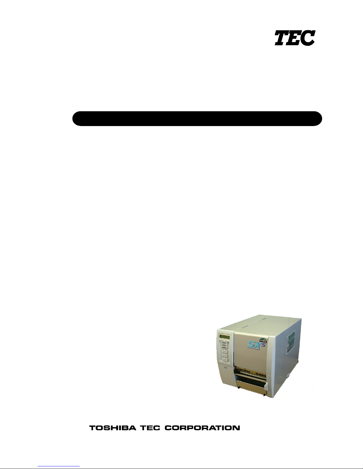
TEC Thermal Printer
B-SX5T-QQ/QP
Owner's Manual
Page 60
CE Compliance (for EU only)
This product complies with the requirements of EMC and Low Voltage Directives including their
amendments.
VORSICHT:
•
Schallemission: unter 70dB (A) nach DIN 45635 (oder ISO 7779)
•
Die für das Gerät Vorgesehene Steckdose muß in der Nähe des Gerätes und leicht zugänglich sein.
Copyright © 2003
by TOSHIBA TEC CORPORATION
All Rights Reserved
570 Ohito, Ohito-cho, Tagata-gun, Shizuoka-ken, JAPAN
Centronics is a registered trademark of Centronics Data Computer Corp.
Microsoft is a registered trademark of Microsoft Corporation.
Windows is a trademark of Microsoft Corporation.
As an ENERGY STAR® Partner, TOSHIBA TEC has determined that this
product meets the ENERGY STAR
®
guidelines for energy efficiency.
-- Outline of the International ENERGY STAR® Office Equipment Program --
The International ENERGY STAR
®
Office Equipment Program is an international program that
promotes energy saving through the penetration of energy efficient computers and other office
equipment. The program backs the development and dissemination of products with functions that
effectively reduce energy consumption. It is an open sy st em in which business proprietors can
participate voluntarily. The targeted products are office equipment such as computers, monitors,
printers, facsimiles, copiers, scanners, and multifunction devices. Their standards and logos are
uniform among participating nations.
E
NERGY STAR is a U.S. registered mark.
This equipment has been tested and found to comply with the limits for a Class A digital device,
pursuant to Part 15 of the FCC Rules. These limits are designed to provide reasonable rotection
against harmful interference when the equipment is operated in a commercial environment. This
equipment generates, uses, and can radiate radio frequency energy and, if not installed and sed in
accordance with the instruction manual, may cause harmful interference to radio communications.
Operations of this equipment in a residential area is likely to cause harmful interference in which case
the user will be required to correct the interference at his own expense.
(for USA only)
Changes or modifications not expressly approved by manufacturer for compliance could void the
user’s authority to operate the equipment.
“This Class A digital apparatus meets all requirements of the Canadian Interference-Causing
Equipment Regulations.”
“Cet appareil numérique de la classe A respecte toutes les exigences du Règlement sur le matériel
brouilleur du Canada.”
(for CANADA only)
Page 61
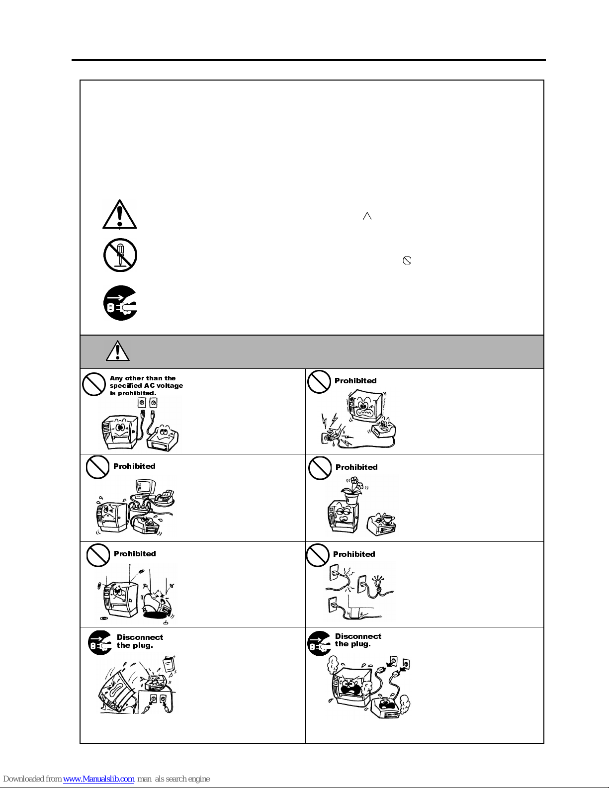
Safety Summary
ENGLISH VERSION EO1-33036
( ) i
6DIHW\6XPPDU\
Personal safety in handling or maintaining the equipment is extremely important. Warnings and Cautions
necessary for safe handling are included in this manual. All warnings and cautions contained in this manual
should be read and understood before handling or maintaining the equipment.
Do not attempt to effect repairs or modifications to this equipment. If a fault occurs that cannot be rectified
using the procedures described in this manual, turn off the power, unplug the machine, then contact your
authorised TOSHIBA TEC representative for assistance.
0HDQLQJVRI(DFK6\PERO
This symbol indicates warning items (including cautions).
Specific warning contents are drawn inside the symbol.
(The symbol on the left indicates a general caution.)
This symbol indicates prohibited actions (prohibited items).
Specific prohibited contents are drawn inside or near the
symbol.
(The symbol on the left indicates “no disassembling”.)
This symbol indicates actions which must be performed.
Specific instructions are drawn inside or near the ● symbol.
(The symbol on the left indicates “disconnect the power cord plug from the outlet”.)
This indicates that there is the risk of
death
or
serious injury
if the
machines are improperly handled contrary to this indication.
Do not use voltages other than
the voltage (AC) specified on the
rating plate, as this may cause
fire
or
electric shock
.
Do not plug in or unplug the power
cord plug with wet hands as this
may cause
electric shock
.
If the machines share the same
outlet with any other electrical
appliances that consume large
amounts of power, the voltage
will fluctuate widely each time
these appliances operate. Be sure
to provide an exclusive outlet for
the machine as this may cause
fire
or
electric shock
.
Do not place metal objects or
water-filled containers such as
flower vases, flower pots or mugs,
etc. on top of the machin es. If
metal objects or spilled liquid enter
the machines, this may cause
fire
or
electric shock
.
Do not insert or drop metal,
flammable or other foreign
objects into the machines through
the ventilation slits, as this may
cause
fire
or
electric shock
.
Do not scratch, damage or modify
the power cords. Also, do not
place heavy objects on, pull on, or
excessively bend the cords, as this
may cause
fire
or
electrical shock.
If the machines are dropped or
their cabinets damaged, first turn
off the power switches and
disconnect the power cord plugs
from the outlet, and then contact
your authorised TOSHIBA TEC
representative for assistance.
Continued use of the machine in
that condition may cause
fire
or
electric shock
.
Continued use of the machines in
an abnormal condition such as
when the machines are producing
smoke or strange smells may cause
fire
or
electric shock
. In these
cases, immediately turn off the
power switches and disconnect the
power cord plugs from the outlet.
Then, contact your authorised
TOSHIBA TEC representative for
assistance.
:$51,1*
$Q\ RWKHU WKDQ WKH
VSHFLILHG $& YROWDJH
LV SURKLELWHG
3URKLELWHG
3URKLELWHG
3URKLELWHG
3URKLELWHG
3URKLELWHG
'LVFRQQHFW
WKH SOXJ
'LVFRQQHFW
WKH SOXJ
Page 62
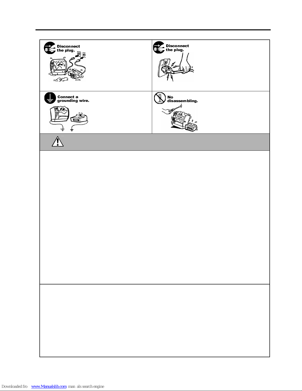
Safety Summary
ENGLISH VERSION EO1-33036
( ) ii
If foreign objects (metal
fragments, water, liquids) enter
the machines, first turn off the
power switches and disconnect
the power cord plugs from the
outlet, and then contact your
authorised TOSHIBA TEC
representative for assistance.
Continued use of the machine in
that condition may cause
fire
or
electric shock
.
When unplugging the power cords,
be sure to hold and pull on the plug
portion. Pulling on the cord portion
may cut or expose the internal wires
and cause
fire
or
electric shock
.
Ensure that the equipment is
properly grounded. Extension
cables should also be grounded.
Fire
or
electric shock
could
occur on improperly grounded
equipment.
Do not remove covers, repair or
modify the machine by yourself.
You may be
injured
by high
voltage, very hot parts or sharp
edges inside the machine.
This indicates that there is the risk of personal
Injury
or
damage
to
objects if the machines are improperly handled contrary to this indication.
Precautions
The following precautions will help to ensure that this machine will continue to function correctly.
●
Try to avoid locations that have the following adverse conditions:
* Temperatures out of the specification * Direct sunlight * High humidity
* Shared power source * Excessive vibration * Dust/Gas
●
The cover should be cleaned by wiping with a dry cloth or a cloth slightly dampened with a mild
detergent solution. NEVER USE THINNER OR ANY OTHER VOLATILE SOLVENT on the plastic
covers.
●
USE ONLY TOSHIBA TEC SPECIFIED paper and ribbons.
●
DO NOT STORE the paper or ribbons where they might be exposed to direct sunlight, high
temperatures, high humidity, dust, or gas.
●
Ensure the printer is operated on a level surface.
●
Any data stored in the memory of the printer could be lost during a printer fault.
●
Try to avoid using this equipment on the same power supply as high voltage equipment or equipment
likely to cause mains interference.
●
Unplug the machine whenever you are working inside it or cleaning it.
●
Keep your work environment static free.
●
Do not place heavy objects on top of the machines, as these items may become unbalanced and fall
causing injury.
●
Do not block the ventilation slits of the machines, as this will cause heat to build up inside the
machines and may cause fire.
●
Do not lean against the machine. It may fall on you and could cause injury.
●
Care must be taken not to injure yourself with the printer paper cutter.
●
Unplug the machine when it is not used for a long period of time.
●
Place the machine on a stable and level surface.
Request Regarding Maintenance
●
Utilize our maintenance services.
After purchasing the machine, contact your authorised TOSHIBA TEC representative for assistance
once a year to have the inside of the machine cleaned. Otherwise, dust will build up inside the
machines and may cause a fire or a malfunction. Cleaning is particularly effective before humid rainy
seasons.
●
Our preventive maintenance service performs the periodic checks and other work required to maintain
the quality and performance of the machines, preventing accidents beforehand.
For details, please consult your authorised TOSHIBA TEC representative for assistance.
●
Using insecticides and other chemicals
Do not expose the machines to insecticides or other volatile solvents. This will cause the cabinet or
other parts to deteriorate or cause the paint to peel.
&$87,21
'LVFRQQHFW
WKH SOXJ
&RQQHFW D
JURXQGLQJ ZLUH
'LVFRQQHFW
WKH SOXJ
1R
GLVDVVHPEOLQJ
Page 63

ENGLISH VERSION EO1-33036
TABLE OF CONTENTS
Page
1. PRODUCT OVERVIEW........................................................................................................E1-1
1.1 Introduction..................................................................................................................E1-1
1.2 Features ......................................................................................................................E1-1
1.3 Unpacking....................................................................................................................E1-1
1.4 Accessories ................................................................................................................E1-2
1.5 Appearance .................................................................................................................E1-3
1.5.1 Dimensions...................................................................................................................E1-3
1.5.2 Front View.....................................................................................................................E1-3
1.5.3 Rear View.....................................................................................................................E1-3
1.5.4 Operation Panel............................................................................................................E1-4
1.5.5 Interior...........................................................................................................................E1-4
2. PRINTER SETUP.................................................................................................................E2-1
2.1 Precautions..................................................................................................................E2-1
2.2 Procedure before Operation.........................................................................................E2-2
2.3 Fitting the Fan Filter.....................................................................................................E2-2
2.4 Connecting the Cables to Your Printer.........................................................................E2-3
2.5 Connecting the Power Cord.........................................................................................E2-4
2.6 Turning the Printer ON/OFF.........................................................................................E2-5
2.6.1 Turning ON the Printer .................................................................................................E2-5
2.6.2 Turning OFF the Printer ...............................................................................................E2-5
2.7 Loading the Media .......................................................................................................
E2-6
2.8 Loading the Ribbon.................................................................................................E2-12
2.9 Inserting the Optional PCMCIA Cards....................................................................E2-14
2.10 Test Print..................................................................................................................E2-15
3. ON LINE MODE....................................................................................................................E3-1
3.1 Operation Panel...........................................................................................................E3-1
3.2 Operation.....................................................................................................................E3-2
3.3 Reset...........................................................................................................................E3-2
3.4 Dump Mode.................................................................................................................E3-3
4. MAINTENANCE ...................................................................................................................E4-1
4.1 Cleaning ......................................................................................................................E4-1
4.1.1 Print Head/Platen/Sensors...........................................................................................E4-1
4.1.2 Covers and Panels.......................................................................................................E4-2
4.1.3 Optional Cutter Module ................................................................................................E4-2
4.2 Care/Handling of the Media and Ribbon ......................................................................E4-3
5. TROUBLESHOOTING..........................................................................................................E5-1
5.1 Error Messages............................................................................................................E5-1
5.2 Possible Problems.......................................................................................................E5-2
5.3 Removing Jammed Media...........................................................................................E5-3
5.4 Threshold Setting.........................................................................................................E5-4
Page 64

ENGLISH VERSION EO1-33036
APPENDIX 1 SPECIFICATIONS...............................................................................................EA1-1
A1.1 Printer........................................................................................................................EA1-1
A1.2 Options ......................................................................................................................EA1-2
A1.3 Media.........................................................................................................................EA1-2
A1.3.1 Media Type .....................................................................................................EA1-2
A1.3.2 Detection Area of the Transmissive Sensor....................................................EA1-3
A1.3.3 Detection Area of the Reflective Sensor.........................................................EA1-4
A1.3.4 Effective Print Area.........................................................................................EA1-4
A1.4 Ribbon.......................................................................................................................EA1-5
APPENDIX 2 MESSAGES AND LEDS .....................................................................................EA2-1
APPENDIX 3 INTERFACE........................................................................................................EA3-1
APPENDIX 4 PRINT SAMPLES................................................................................................EA4-1
GLOSSARIES
INDEX
CAUTION!
1. This manual may not be copied in whole or in part without prior written permission of TOSHIBA TEC.
2. The contents of this manual may be changed without notification.
3. Please refer to your local Authorised Service representative with regard to any queries you may have in
this manual.
This is a Class A product. In a domestic environment this product may cause radio interference in
which case the user ma
y
be required to take adequate measures.
WARNING!
Page 65

1. PRODUCT OVERVIEW
ENGLISH VERSION EO1-33036
1.1 Introduction
E1- 1
1. PRODUCT OVERVIEW
1.1 Introduction
1.2 Features
1.3 Unpacking
Thank you for choosing the TEC B-SX5T series thermal printer. This
Owner’s Manual contains from general set-up through how to confirm
the printer operation using a test print, and should be read carefully to
help gain maximum performance and life from your printer. For most
queries please refer to this manual and keep it safe for future reference.
Please contact your TOSHIBA TEC representative for further
information concerning this manual.
This printer has the following features:
• The print head block can be opened providing smooth loading of
media and ribbon.
• Various kinds of media can be used as the media sensors can be
moved from the centre to the left edge of the media.
• The strip module, ribbon saving module, and expansion I/O interface
board are provided on this printer as standard.
• When the optional interface board is installed, Web functions such as
remote maintenance and other advanced network features are
available.
• Superior hardware, including the specially developed 12 dots/mm
(306 dots/inch) thermal print head which will allow very clear print at
a printing speed of 76.2 mm/sec. (3 inches/sec.), 127.0 mm/sec. (5
inches/sec.), or 203.2 mm/sec. (8 inches/sec.).
• Besides the optional Cutter Module, there are also an optional
PCMCIA Interface Board, LAN Interface Board, and the USB
Interface Board.
Unpack the printer as per the Unpacking Instructions supplied with the
printer.
NOTES:
1. Check for damage or
scratches on the printer.
However, please note that
TOSHIBA TEC shall have no
liability for any damage of
any kind sustained during
transportation of the product.
2. Keep the cartons and pads
for future transportation of
the printer.
Page 66

1. PRODUCT OVERVIEW
ENGLISH VERSION EO1-33036
1.4 Accessories
E1- 2
1.4 Accessories
When unpacking the printer, please make sure all the following
accessories are supplied with the printer.
US Power Cord (1 pc.)
(P/No. FBCB0030203)
QQ model only
CD-ROM (1 pc.)
QQ (P/No.: 7FM00332000)
QP (P/No.: 7FM00256000)
Rewinder Guide Plate (1 pc.)
(P/No.: FMBD0034501)
EU Power Cord (1 pc.)
(P/No.EKA-0030001)
QP model onl
y
Fan Filter (1 pc.)
(P/No. FMBB0036801)
SMW-4x8 Sems Screws (2 pcs.)
(P/No.: X0-00161000)
Page 67
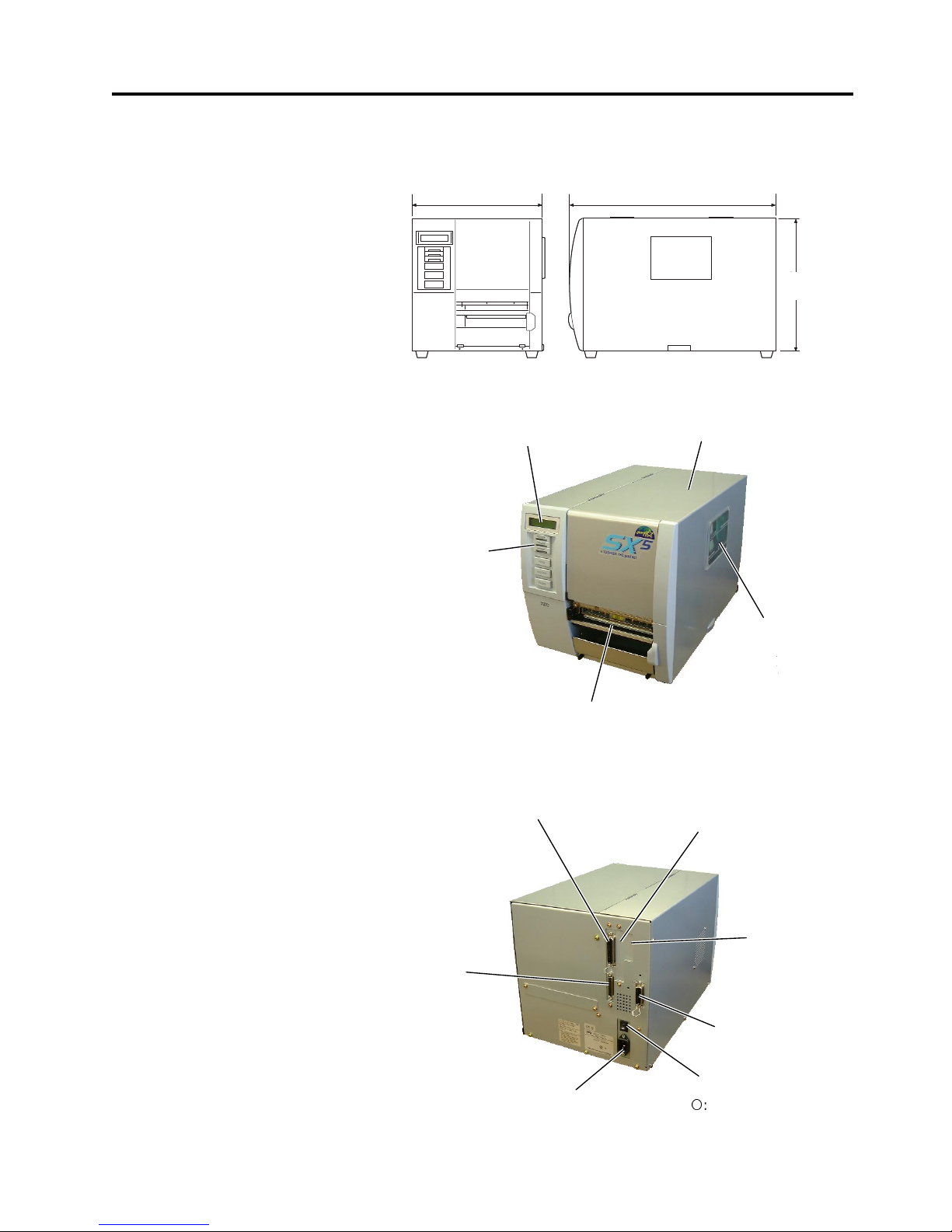
1. PRODUCT OVERVIEW
ENGLISH VERSION EO1-33036
1.5 Appearance
E1- 3
1.5 Appearance
1.5.1 Dimensions
1.5.2 Front View
1.5.3 Rear View
The names of the parts or units introduced in this section are used in the
following chapters.
Dimensions in mm (inches)
LCD Message Display
Operation Panel
Power Switch
{
: OFF
|: ON
Media Outlet
Top Cover
Expansion I/O
Interface Connector
Serial Interface
Connector (RS-232C)
Parallel Interface
Connector (Centronics)
Supply Window
PCMCIA Card Slot (Option),
USB Connector (Option), or
LAN Connector (Option)
AC Power Inlet
291 460
308
308
(12.1)
291 (11.5)
460 (18.1)
USB Connector
(Option) or LAN
Connector (Option)
Page 68
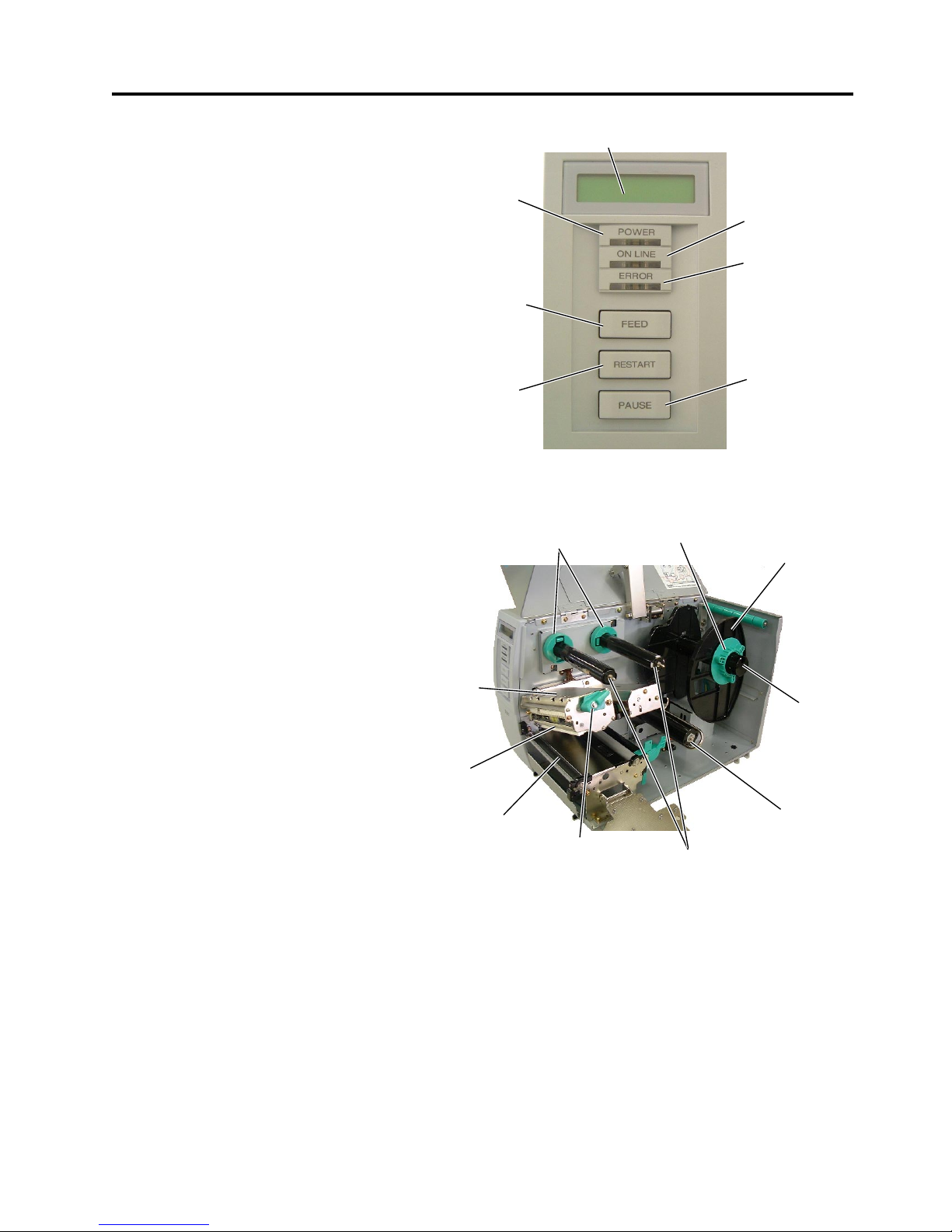
1. PRODUCT OVERVIEW
ENGLISH VERSION EO1-33036
1.5 Appearance
E1- 4
1.5.4 Operation Panel
1.5.5 Interior
Please see Section 3.1 for further information about the Operation Panel.
LCD Message Display
ON LINE LED
(Green)
ERROR LED
(Red)
[PAUSE]
key
POWER LED
(Green)
[FEED]
ke
y
[RESTART]
ke
y
Ribbon Stoppe
r
Print Head Block
Head Lever
Ribbon Shaft
Supply Holder
Locking Ring
Supply Shaft
Print Head
Platen
Take-up Spool
Page 69

2. PRINTER SETUP
ENGLISH VERSION EO1-33036
2.1 Precautions
E2- 1
2. PRINTER SETUP
2.1 Precautions
This section outlines the procedures to setup your printer prior to its
operation. The section includes precautions, connecting cables,
assembling accessories, loading media and ribbon, inserting the optional
memory card, and performing a test print.
To insure the best operating environment, and to assure the safety of the
operator and the equipment, please observe the following precautions.
• Operate the printer on a stable, level, operating surface in a location
free from excessive humidity, high temperature, dust, vibration or
direct sunlight.
• Keep your work environment static free. Static discharge can cause
damage to delicate internal components.
• Make sure that the printer is connected to a clean source of AC
Power and that no other high voltage devices that may cause line
noise interference are connected to the same mains.
• Assure that the printer is connected to the AC mains with a three-
prong power cable that has the proper ground (earth) connection.
• Do not operate the printer with the cover open. Be careful not to
allow fingers or articles of clothing to get caught into any of the
moving parts of the printer especially the optional cutter mechanism.
• Make sure to turn off the printer power and to remove the power cord
from the printer whenever working on the inside of the printer such
as changing the ribbon or loading the media, or when cleaning the
printer.
• For best results, and longer printer life, use only TOSHIBA TEC
recommended media and ribbons.
• Store the media and ribbons in accordance with their specifications.
• This printer mechanism contains high voltage components; therefore
you should never remove any of the covers of the machine as you
may receive an electrical shock. Additionally, the printer contains
many delicate components that may be damaged if accessed by
unauthorised personnel.
• Clean the outside of the printer with a clean dry cloth or a clean cloth
slightly dampened with a mild detergent solution.
• Use caution when cleaning the thermal print head as it may become
very hot while printing. Wait until it has had time to cool before
cleaning. Use only the TOSHIBA TEC recommended print head
cleaner to clean the print head.
• Do not turn off the printer power or remove the power plug while the
printer is printing or while the ON LINE lamp is blinking.
Page 70
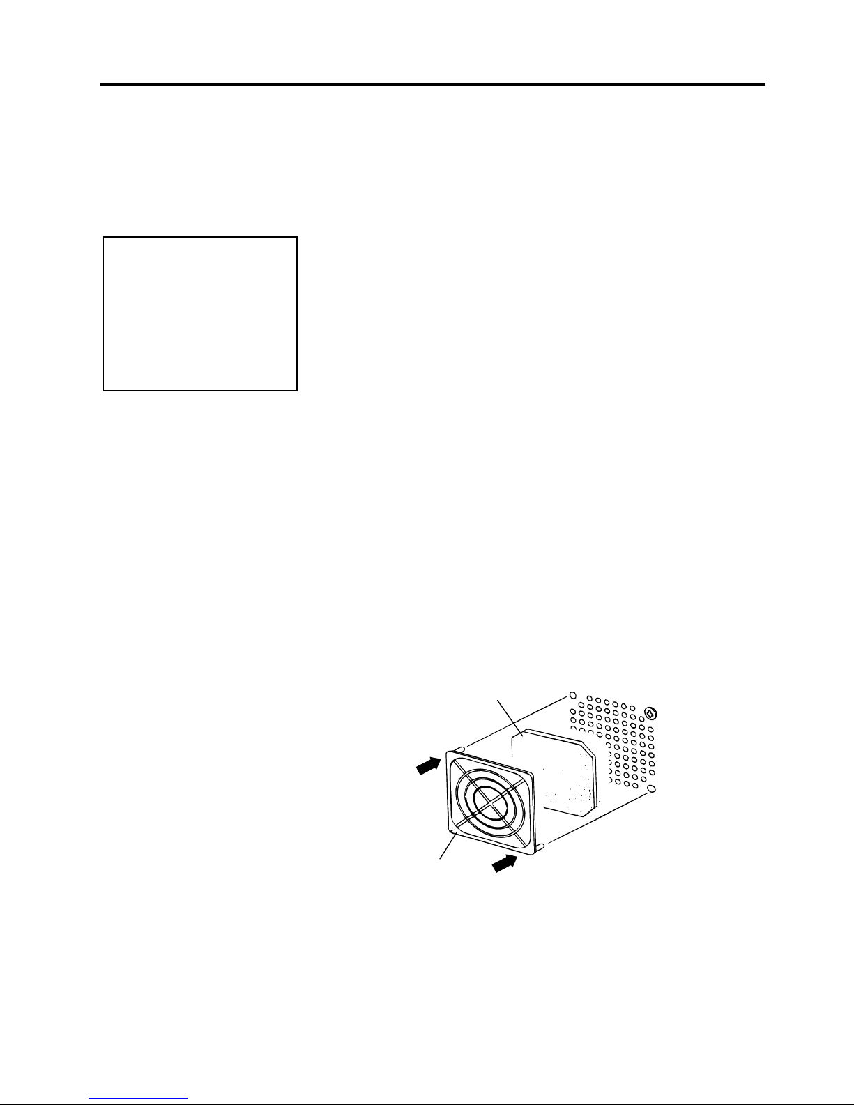
2. PRINTER SETUP
ENGLISH VERSION EO1-33036
2.2 Procedure before Operation
E2- 2
2.2 Procedure before
Operation
2.3 Fitting the Fan Filter
This section describes the outline of the printer setup.
1.
Unpack the accessories and printer from the box.
2.
Refer to Safety Precautions in this manual and set up the printer at a
proper location.
3.
Fit the Fan Filter to the printer. (Refer to Section 2.3.)
4.
The host computer must have a serial, Centronics parallel, USB or
LAN port. (Refer to Section 2.4.)
5.
Be sure to insert the power cord plug into an AC outlet. (Refer to
Section 2.5.)
6.
Load the media. (Refer to Section 2.7.)
7.
Adjust the position of the Feed Gap Sensor or Black Mark Sensor
depending on the media being used. (Refer to Section 2.7.)
8.
Load the ribbon. (Refer to Section 2.8.)
9.
Turn the power ON. (Refer to Section 2.6.)
10.
Perform a test print. (Refer to Section 2.10.)
11.
Install the Printer Drivers. (Refer to the Printer Driver Manual.)
When installing the printer, it is important to ensure that the Fan Filter is
attached before using the printer.
The Fan Filter consists of 2 parts:
(1) Filter Pad
(2) Filter Retainer
To fit the Fan Filter, put the Filter Pad inside the Filter Retainer and
simply press into place as shown in the diagram below, ensuring
connecting pins are aligned with the connecting holes.
NOTE:
To communicate with the host
computer, one of the following
cables is required.
(1) RS-232C cable: 25 pins
(2) Centronics cable: 36 pins
(3) USB: B plug (Option)
(4) LAN: 10 Base-T or 100
Base-TX (Option)
Filter Pad
Filter Retainer
Snap On
Snap On
Page 71
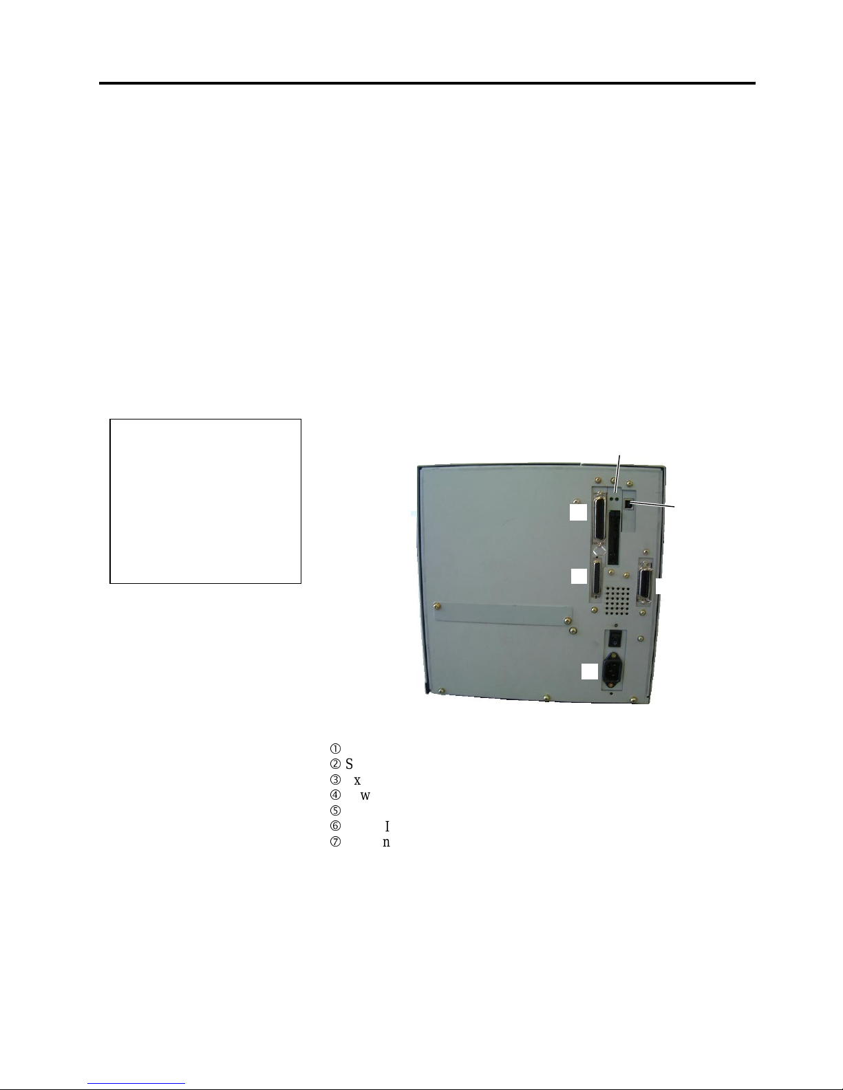
2. PRINTER SETUP
ENGLISH VERSION EO1-33036
2.4 Connecting the Cables to Your P ri nter
E2- 3
2.4 Connecting the
Cables to Your
Printer
The following paragraphs outline how to connect the cables from the
printer to your host computer, and will also show how to make cable
connections to other devices. Depending on the application software
you use to print labels, there are 4 possibilities for connecting the
printer to your host computer. These are:
•
A serial cable connection between the printer’s RS-232 serial
connector and one of your host computer’s COM ports.
(Refer to APPENDIX 3.)
•
A parallel cable connection between the printer’s standard parallel
connector and your host computer’s parallel port (LPT).
•
An Ethernet connection using the optional LAN board.
•
A USB cable connection between the printer’s optional USB
connector and your host computer’s USB port. (Conforming to
USB 1.1)
The diagram below shows all the possible cable connections to the
current version of the printer.
c
Parallel Interface Connector (Centronics)
d
Serial Interface Connector (RS-232C)
e
Expansion I/O Interface Connector
f
Power Inlet
g
USB Interface Connector (Option)
h
PCMCIA Card Slot (Option)
i
LAN Interface Connector (Option)
c
d
e
f
g, h
,
or
i
NOTES:
1. The picture on the right shows
the layout of the interface
connectors when the options
are fully installed. It may be
different depending on your
system configuration.
2. The USB interface and LAN
interface cannot be used at the
same time.
gori
Page 72

2. PRINTER SETUP
ENGLISH VERSION EO1-33036
2.5 Connecting the Power Cord
E2- 4
2.5 Connecting the
Power Cord
1.
Make sure that the printer Power Switch is in the OFF (
{
{
) position.
2.
Connect the Power Cord to the printer as shown in the figure below.
3.
Plug the other end of the Power Cord into a grounded outlet as shown
in the figure below.
[QQ Type] [QP Type]
CAUTION!
1. Make sure that the printe
r
Power Switch is turned to
the OFF position (
{
)
before connecting the
Power Cord to prevent
possible electric shock or
damage to the printer.
2. Use only the Power Cord
supplied with the printer.
Use of any other cord
may cause electric shock
or fire.
3. Connect the Power Cord
to a supply outlet with a
properly grounded
(earthed) connection.
Power Cord
Power Cord
Power Cord
Power Switch
Page 73
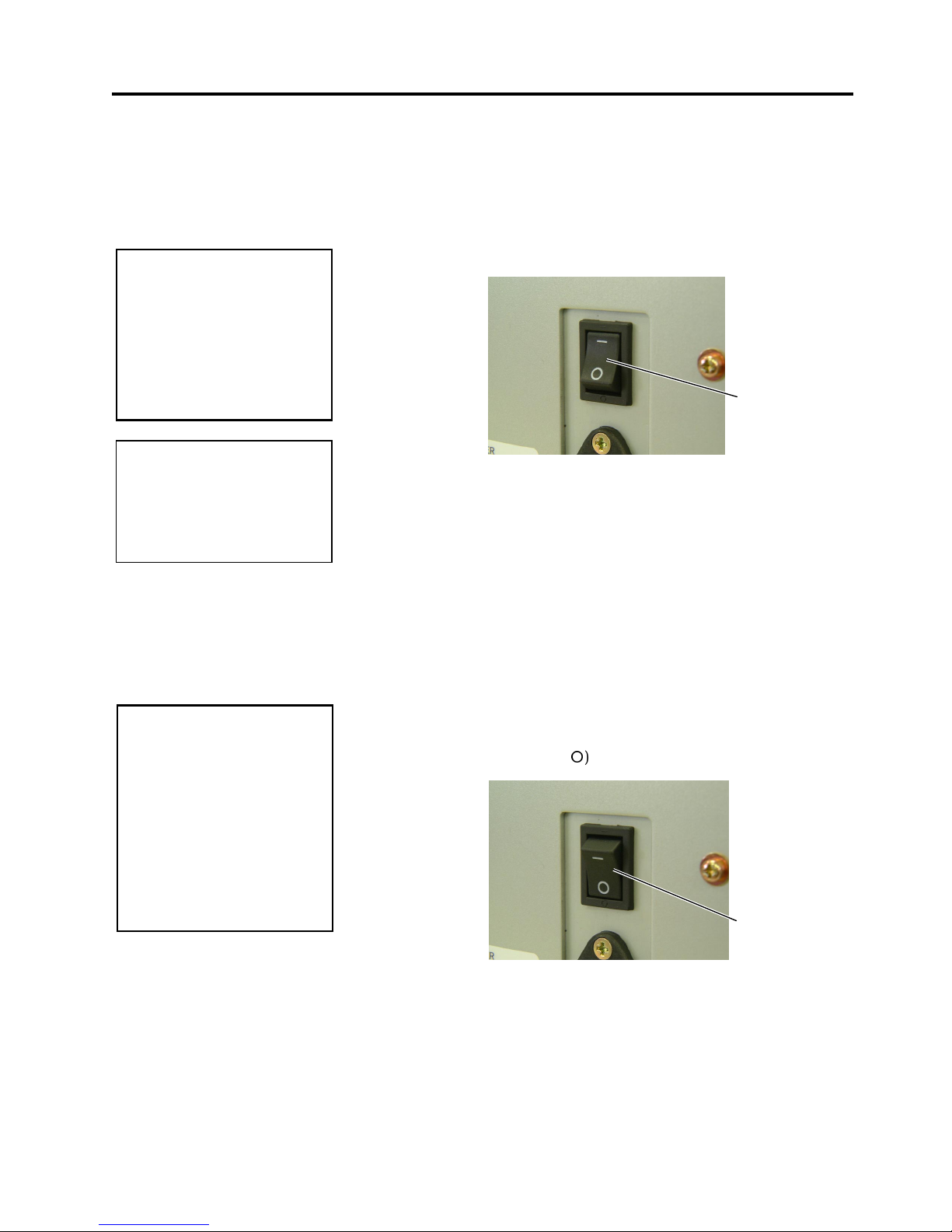
2. PRINTER SETUP
ENGLISH VERSION EO1-33036
2.6 Turning the Printer ON/OFF
E2- 5
2.6 Turning the Printer
ON/OFF
2.6.1 Turning ON the Printer
2.6.2 Turning OFF the Printer
When the printer is connected to your host computer it is good practice to
turn the printer ON before turning on your host computer and turn OFF
your host computer before turning off the printer.
1.
To turn ON the printer power, press the Power Switch as shown in the
diagram below. Note that (
|
)
is the power ON side of the switch.
2.
Check that the ON LINE message appears in the LCD Message
Display and that the ON LINE and POWER LED lights are
illuminated.
1.
Before turning off the printer Power Switch verify that the ON LINE
message appears in the LCD Message Display and that the ON LINE
LED light is on and is not flashing.
2.
To turn OFF the printer power press the Power Switch as shown in the
diagram below. Note that ({)
is the power OFF side of the switch.
CAUTION!
Use the power switch to turn
the printer On/Off. Plugging
or unplugging the Power
Cord to turn the printer
On/Off may cause fire, an
electric shock, or damage to
the printer.
CAUTION!
1. Do not turn off the printer
power while the media is
being printed as this may
cause a paper jam or
damage to the printer.
2. Do not turn off the printer
power while the ON LINE
lamp is blinking as this
may cause damage to
your computer.
Power Switch
Power Switch
NOTE:
I
f a message other than ON
L
INE appears on the display or
the ERROR LED lamp is
illuminated, go to Section 5.1,
Error Messages.
Page 74
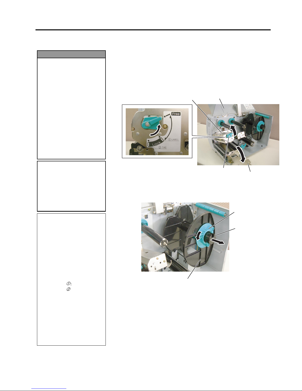
2. PRINTER SETUP
ENGLISH VERSION EO1-33036
2.7 Loading the Media
E2- 6
2.7 Loading the Media
The following procedure shows the steps to properly load the media into
the printer so that it feeds straight and true through the printer.
The printer prints both labels and tags.
1.
Turn off the power and open the Top Cover.
2.
Turn the Head Lever to
Free
position, then release the Ribbon Shaft
Holder Plate.
3.
Open the Print Head Block.
4.
Turn the Locking Ring counterclockwise and remove the Supply
Holder from the Supply Shaft.
1. Do not touch any moving
parts. To reduce the risk
of fingers, jewellery,
clothing, etc., being
drawn into the moving
parts, be sure to load the
media once the printer
has stopped moving
completely.
2. The Print Head becomes
hot immediately after
printing. Allow it to cool
before loading the media.
3. To avoid injury, be careful
not to trap your fingers
while opening or closing
the cover.
WARNING!
NOTES:
1. When the Head Lever is
turned to
Free
position, the
Print Head is raised.
2. To allow printing the Head
Lever must be set to
Lock
position. (This ensures that
the Print Head is closed.)
There are two head pressure
levels in the
Lock
position.
Set the Head Lever depending
on the media type:
Position c: Labels
Position d: Tags
However, proper position
may differ depending on
media. For details, refer to
TOSHIBA TEC authorised
service representative.
3. Do not turn the Locking Ring
counter-clockwise too far or it
may come off the Supply
Holder.
CAUTION!
Be careful not to touch the
Print Head Element when
raising the Print Head Block.
Failure to do this may cause
missing dots by static
electricity or other print
q
uality problems.
Top Cover
Head Lever
Print Head Block
Locking Ring
Supply Holder
Supply Shaft
Ribbon Shaft
Holder Plate
Page 75

2. PRINTER SETUP
ENGLISH VERSION EO1-33036
2.7 Loading the Media
E2- 7
2.7 Loading the Media
(Cont.)
5.
Put the media on the Supply Shaft.
6.
Pass the media around the Damper, then pull the media towards the
front of the printer.
7.
Align the projection of the Supply Holder with the groove of the
Supply Shaft, and push the Supply Holder against the m edia until the
media is held firmly in place. This will centre the media
automatically.
Then turn the Locking Ring clockwise to secure the Supply Holder.
8.
Place the media between the Media Guides, adjust the Media Guides
to the media width, and tighten the Locking Screw.
9.
Check that the media path through the printer is straight. The media
should be centred under the Print Head.
NOTE:
D
o not over-tighten the Locking
R
ing of the Supply Holder.
Supply Shaft
Suppl
y
Holder
Damper
Locking Ring
Projection
Media
Media Guide
Supply Holder
Media Guide
Print Head
Locking Screw
Media
Damper
Media
In case of a label rolled with
the print side facing inside.
In case of a label rolled with
the print side facing outside.
Page 76
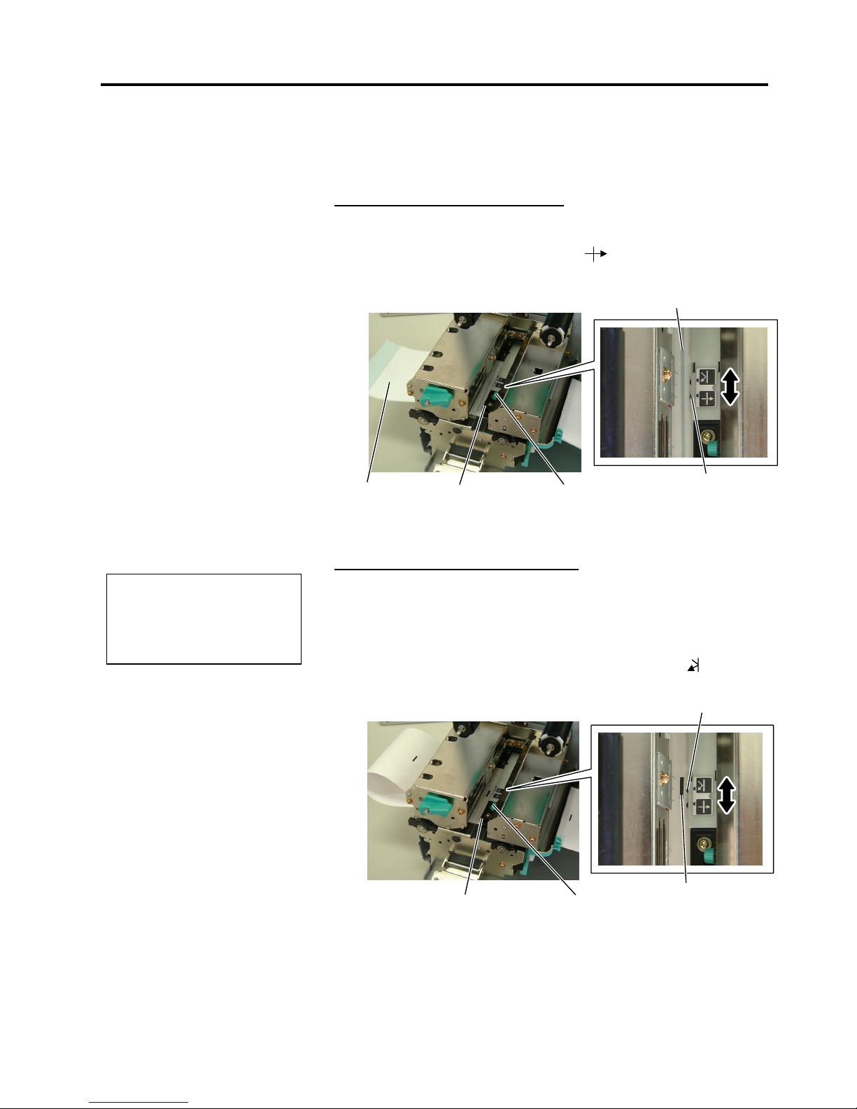
2. PRINTER SETUP
ENGLISH VERSION EO1-33036
2.7 Loading the Media
E2- 8
2.7 Loading the Media
(Cont.)
10.
Lower the Print Head Block until it stops.
11.
After loading the media, it may be necessary to set the Media
Sensors used to detect the print start position for label or tag
printing.
Setting the Feed Gap Sensor position
(1) Remove the Locking Screw that secures the Media Sensor.
(2) Manually move the Media Sensor so that the Feed Gap Sensor is
positioned at the centre of the labels. ( indicates the position of
the Feed Gap Sensor).
(3) Tighten the Locking Screw.
Setting the Black Mark Sensor position
(1) Remove the Locking Screw that secures the Media Sensor.
(2) Pull about 500 mm of media out of the front of the printer, turn the
media back on itself and feed it under the Print Head past the sensor
so that the black mark can be seen from above.
(3) Manually move the Media Sensor so that the Black Mark Sensor is
in line with the centre of the black mark on the media. ( indicates
the position of the Black Mark Sensor).
(4) Tighten the Locking Screw.
NOTE:
B
e sure to set the black mark
sensor to detect the centre of the
black mark, otherwise a paper
j
am or no paper error may occur.
Locking Screw
Black Mark Sensor
Black Mark
Feed Gap Sensor
Label
Gap
Locking Screw
Media Sensor
Media Sensor
Page 77

2. PRINTER SETUP
ENGLISH VERSION EO1-33036
2.7 Loading the Media
E2- 9
2.7 Loading the Media
(Cont.)
12.
There are four issue modes available on this printer. How to set the
media for each mode is provided below.
Batch mode
In the batch mode, the media is continuously printed and fed until the
number of labels/tags specified in the issue command have been printed.
Strip mode
In the strip mode, the backing paper is automatically removed from the
label at the Strip Plate as each label is printed.
(1) Remove enough labels from the leading edge of the media to leave
500mm of backing paper free.
(2) Insert the backing paper under the Strip Plate.
(3) Wind the backing paper onto the Take-up Spool and fix it in position
with the Take-up Clip. (Wind the paper counterclockwise around
the spool as this is the direction it rotates.)
(4) Rotate the Take-up Spool anti-clockwise a few times to remove any
slack in the backing paper.
(5) Set the Selection Switch mounted on the Rewinder Assembly to
STANDARD/PEEL OFF
position.
Take-up Clip
Take-up Spool
Black Screw
NOTES:
1. Be sure to set the Selection
Switch to
STANDARD/
PEEL OFF
position.
2. The backing paper is easier
to feed back to the Take-Up
Spool if the Front Plate is
removed.
3. Fit the Take-Up Clip so that
the longer side of the clip is
fitted into the shallow groove
in the Take-Up Spool.
4. The backing paper can be
wound directly onto the Takeup Spool or a paper core.
When using the Take-up
Spool, detach the Holder
Stopper by removing the B3x4 screw. Otherwise, it may
be difficult to pull out the
wound backing paper roll. .
Holder Stopper
B-3x4 Screw
Take-up Spool
Take-up Clip
When using a paper core, put
the core on the Take-up Spool
with the Holder Stopper on it,
and attach the top edge of the
backing paper to the core
with adhesive tape. The
Take-up Clip is not
necessary.
This winding method is
applicable to the Built-in
Rewinder mode.
Strip Plate
Backing Paper
Front Plate
Page 78
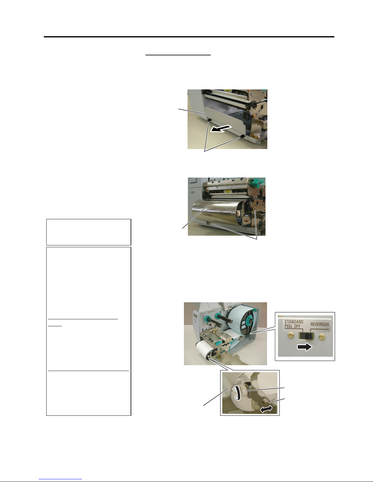
2. PRINTER SETUP
ENGLISH VERSION EO1-33036
2.7 Loading the Media
E2-10
2.7 Loading the Media
(Cont.)
Build-in rewinder mode
When the Rewinder Guide Plate is attached, the Take-up Spool can be
used as a Built-in Rewinder to take up the printed media.
(1) Remove the two Black Screws to detach the Front Plate.
(2) Attach the Rewinder Guide Plate to the Strip Plate with the SMW-
4x8 sems screws.
(3) Insert the media under the Rewinder Guide Plate.
(4) Wind the media onto the Take-up Spool and fix it in position with
the Take-up Clip.
(5) Rotate the Take-up Spool counterclockwise a few times to remove
any slack in the media.
(6) Set the Selection Switch mounted on the Rewinder Assembly to
REWINDER
position.
NOTE:
B
e sure to set the Selection
Switch to REWINDER position.
ADJUSTMENT:
I
f the media skews when using
the Built-in Rewinder, turn the
A
djustment Knob of the
R
ewinder Guide Plate to correct
the media feed. Clockwise turn
moves the Rewinder Guide Plate
f
orward and counter-clockwise
moves it backward.
When the media skews to the
right:
L
oosen the SM-4x8 screw, turn
the Adjustment Knob clockwise,
and then tighten the SM-4x8
screw when the Rewinder Guide
Plate is positioned correctly.
When the media skews to the left:
L
oosen the SM-4x8 screw, turn
the Adjustment Knob counterclockwise, and tighten the SM4x8 screw when the Rewinder
Guide Plate is positioned
correctly.
Rewinder
Guide Plate
SM-4x8 Screw
Adjustment Knob
Front Plate
Black Screw
Rewinder
Guide Plate
SMW-4x8 Screw
Page 79
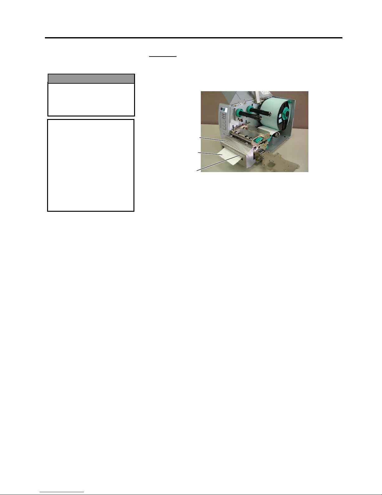
2. PRINTER SETUP
ENGLISH VERSION EO1-33036
2.7 Loading the Media
E2-11
2.7 Loading the Media
(Cont.)
Cut mode
When the optional Cutter Module is fitted, the media is automatically cut.
A swing cutter and a rotary cutter are available as an option, but they are
used in the same way.
Insert the leading edge of the media into the Media Outlet of the Cutter
Module.
13.
If the loaded media is direct thermal media (a chemically treated
surface), the media loading procedure is now completed. Close the
Ribbon Shaft Holder Plate, and turn the Head Lever to
Lock
position to close. Then, close the Top Cover.
If the media is thermal transfer media, it is also necessary to load a
ribbon. Refer to Section 2.8 Loading the Ribbon.
Media Outlet
Media
Cutter Module
CAUTION!
1. Be sure to cut the backing
paper of the label.
Cutting labels will cause
the glue to stick to the
cutter which may affect
the cutter quality and
shorten the cutter life.
2. Use of tag paper when
the thickness exceeds the
specified value may affect
the cutter life.
The cutter is sharp, so care
must be taken not to injure
y
ourself when handling the
cutter.
WARNING!
Page 80
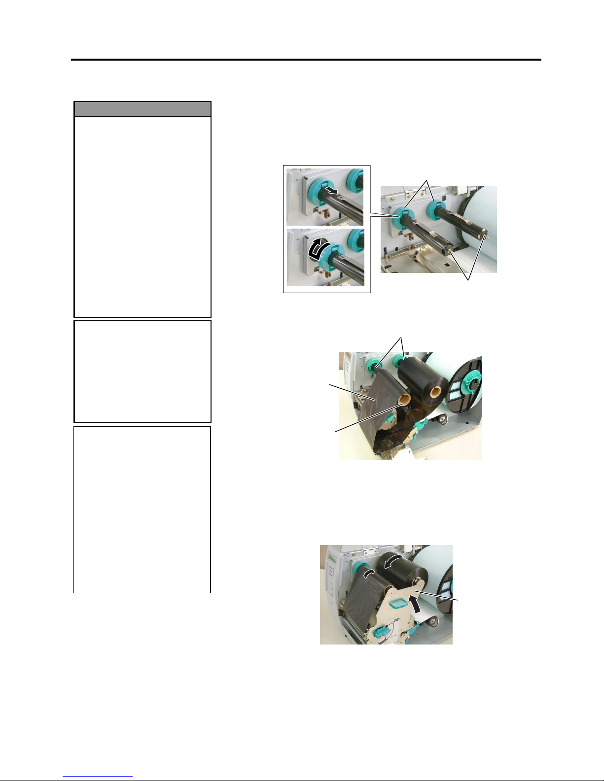
2. PRINTER SETUP
ENGLISH VERSION EO1-33036
2.8 Loading the Ribbon
E2-12
2.8 Loading the Ribbon
There are two types of media available for printing on: these are thermal
transfer media and direct thermal media (a chemically treated surface).
DO NOT LOAD a ribbon when using a direct thermal media.
1.
Rotate the Ribbon Stoppers counterclockwise by 90° and move them
back to the end of the Ribbon Shafts. Restore the Ribbon Stoppers to
the former orientation by turning them clockwise.
2.
Leaving plenty of slack between the ribbon spools, place the ribbon
onto the Ribbon Shafts as shown below.
3.
Slide the Ribbon Stoppers along the Ribbon Shafts to a position where
the ribbon is centred when fitted.
4.
Lower the Print Head Block and set the Ribbon Shaft Holder Plate
aligning its holes with the Ribbon Shafts.
5.
Take up any slack in the ribbon. Wind the leading tape onto the
ribbon take-up roll until the ink ribbon can be seen from the front of
the printer.
6.
Turn the Head Lever to
Lock
position to close the Print Head.
7.
Close the Top Cover.
CAUTION!
Be careful not touch the
Print Head Element when
raising the Print Head Block.
Failure to do this may cause
missing dots by static
electricity or other print
q
uality problems.
1. Do not touch any moving
parts. To reduce the risk
of fingers, jewellery,
clothing, etc., being
drawn into the moving
parts, be sure to load the
ribbon once the printer
has stopped moving
completely.
2. The print head becomes
hot immediately after
printing. Allow it to cool
before loading the ribbon.
3. To avoid injury, be carefu
l
not to trap your fingers
while opening or closing
the cover.
WARNING!
Ribbon Shaft
Ribbon Take-up Roll
Print Head Block
Ribbon Stopper
Ribbon Shaft
NOTES:
1. Be sure to remove any slack in
the ribbon when printing.
Printing with a wrinkled
ribbon will lower the print
quality.
2. The Ribbon Sensor is mounted
on the rear of the Print Head
Block to detect a ribbon end.
When a ribbon end is
detected, “NO RIBBON”
message will appear on the
display and the ERROR LED
will illuminate.
Ribbon Shaft
Holder Plate
Page 81

2. PRINTER SETUP
ENGLISH VERSION EO1-33036
2.8 Loading the Ribbon
E2-13
2.8 Loading the Ribbon
(Cont.)
Auto Ribbon Saving Mode
When the auto ribbon saving function is selected, it will be activated to
reduce ribbon loss when a no print area extends more than 20 mm. For
further information on this function, please ask a TOSHIBA TEC
authorised service representative.
NOTE:
Ribbon loss per ribbon saving
varies according to the relation
between the outer roll diameter
of the used ribbon and the print
speed.
Print speed Ribbon loss/Ribbon saving
3”/sec. Approx. 5 mm
5”/sec. Approx. 8 mm
8”/sec. Approx. 17 mm
Page 82
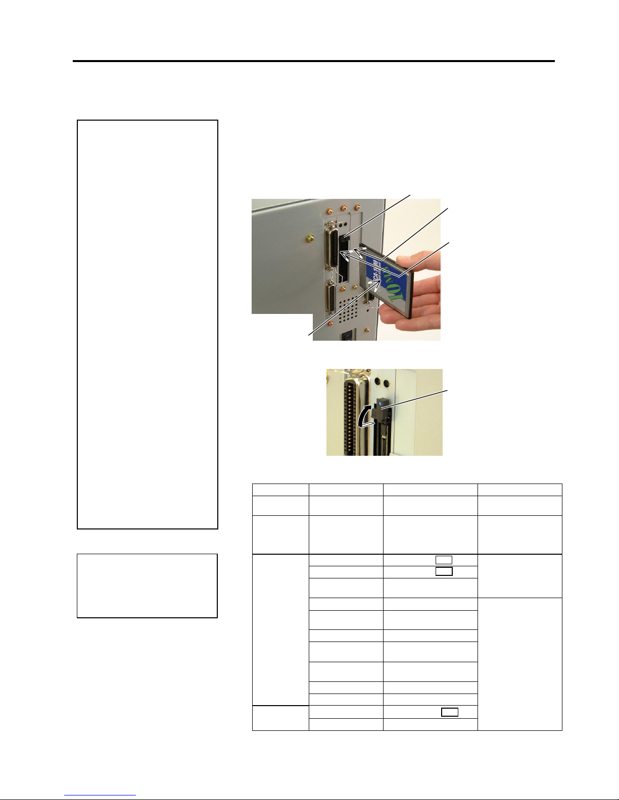
2. PRINTER SETUP
ENGLISH VERSION EO1-33036
2.9 Inserting the Optional PCMCIA Cards
E2-14
2.9 Inserting the Optional
PCMCIA Cards
When the optional PCMCIA Interface Board is installed into the printer,
there will be two PCMCIA slots available as shown in the figure below.
This allows the use of Flash Memory type Cards or I/O Cards such as
LAN Cards. The following paragraphs outline how to insert PCMCIA
cards.
1.
Make sure that the printer’s Power Switch is in the OFF position.
2.
Hold the PCMCIA Card so that the side with the model name faces
left. Insert the card into the proper slot until the Eject Button pops
out.
3.
Slightly pull and fold the Eject Button upward.
4.
The following PCMCIA cards can be used.
Type Maker Description Remarks
ATA Card
San Disk,
Hitachi
A card conforming to the
PC card ATA standard
----------
LAN Card 3 COM 3CCE589ET Series
Install into the slot (2)
only. (This card
installed into the slot
(1) will not work.)
Maxell
EF-4M-TB
Maxell EF-4M-TB
Centennial
Technologies INC.
FL04M-15-11119-03
Read/Write
INTEL
IMC004FLSA
Simple
TECNOLOGY
STI-FL/4A
Mitsubishi
MF84M1-G7DAT01
PC Card KING
MAX
FJN-004M6C
Centennial
Technologies Inc.
FL04M-20-11138-67
PC Card
FJP-004M6R
Flash Memory
Card (4 MB)
Mitsubishi
MF84M1-GMCAV01
Maxell
EF-1M-TB
Flash Memory
Card (1 MB)
Mitsubishi
MF81M1-GBDAT01
Read (See NOTE.)
CAUTION!
1. To protect PC cards,
discharge static
electricity from your body
by touching the metal
cabinet of the printer
before touching the card.
2. Before inserting or
removing a PCMCIA
card make sure that the
printer’s power is turned
off.
3. Be sure to protect
PCMCIA Cards when not
in use by putting them
into their protective
covers.
4. Do not subject the card
to any shocks or
excessive force nor
expose the card to
extremes in temperature
or humidity.
5
. The card may be
inserted into the slot
halfway even in the
wrong orientation.
However, the slot is
safety designed so that
the card will not seat
against the connector
pins.
Slot 2:
(I/O type cards such as
LAN
cards)
Slot 1:
(Memory type cards only)
Eject Button
NOTE:
R
eading a read-only-type flash
memory is possible if it has been
used on the TOSHIBA TEC
p
rinter, such as B-472 and B-572.
CC
DC
AA
Model Name
Printed Side
Eject Button
Page 83
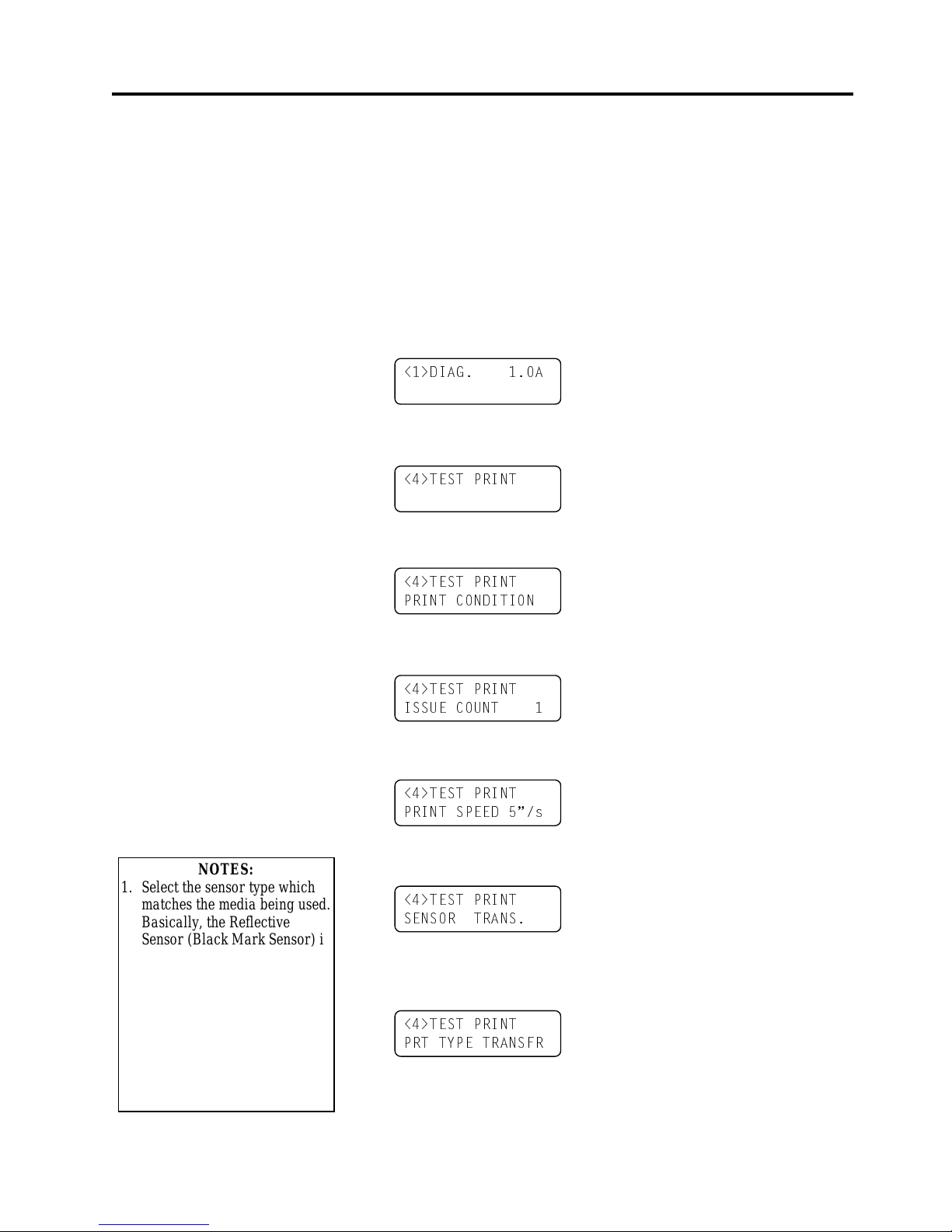
2. PRINTER SETUP
ENGLISH VERSION EO1-33036
2.10 Test Print
E2-15
2.10 Test Print
A print test should be performed to check that the printer is operating
correctly.
The following paragraphs guide you through the diagnostic procedure for
test label printing. Please follow the step-by-step procedures exactly for
best results.
1.
Use label stock for the test print. For best results, use labels that are
76 mm or longer in length.
2.
Press and hold the
[FEED]
and
[PAUSE]
keys while turning on the
printer power switch. The LCD Message Display will show the
following message.
3.
Press the
[FEED]
key three times to advance to the test print mode as
indicated by the following message in the LCD Message Display.
4.
Press the
[PAUSE]
key and the print condition setting display will
appear.
5.
Press the
[PAUSE]
key and the issue count setting display will
appear. Set the issue count with the
[FEED]
or
[RESTART]
key.
6.
Press the
[PAUSE]
key and the print speed setting display will
appear. Set the print speed with the
[FEED]
or
[RESTART]
key.
7.
Press the
[PAUSE]
key and the sensor type setting display will
appear. Select the sensor type with the
[FEED]
or
[RESTART]
key.
8.
Press the
[PAUSE]
key and the print mode setting display will
appear. Select the print mode with the
[FEED]
or
[RESTART]
key.
!',$* $
!7(67 35,17
!7(67 35,17
35,17 &21',7,21
!7(67 35,17
6(1625 75$16
!7(67 35,17
,668( &2817
!7(67 35,17
35,17 63((' ´V
NOTES:
1. Select the sensor type which
matches the media being used.
Basically, the Reflective
Sensor (Black Mark Sensor) is
for tag paper, and the
Transmissive Sensor (Feed
Gap Sensor) is for labels.
2. Select the print mode which
matches the media being used.
Basically, the thermal transfer
is with ribbon, and the
thermal direct is without
ribbon.
!7(67 35,17
357 7<3( 75$16)5
Page 84
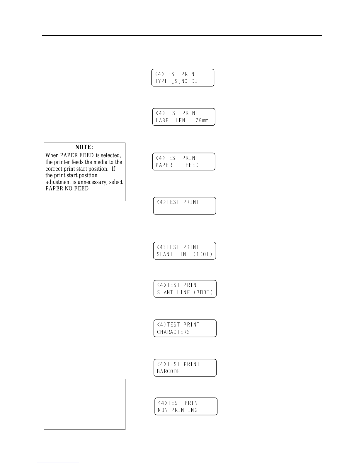
2. PRINTER SETUP
ENGLISH VERSION EO1-33036
2.10 Test Print
E2-16
2.10 Test Print (Cont.)
9.
Press the
[PAUSE]
key and the issue mode setting display will
appear. Select the issue mode with the
[FEED]
or
[RESTART]
key.
10.
Press the
[PAUSE]
key and the media size setting display will
appear. Select the media size with the
[FEED]
or
[RESTART]
key.
11.
Press the
[PAUSE]
key and the paper feed setting display will
appear. Select whether or not a paper feed is performed with the
[FEED]
or
[RESTART]
key.
12.
When the
[PAUSE]
key is pressed, one blank media will be issued.
Then the LCD Message Display will return to showing the test print
start message.
13.
Press the
[PAUSE]
key and the n
[FEED]
key. When pressing the
[PAUSE]
key, the printer will print the specified issue counts of the
slant lines (1 dot).
14.
Press the
[FEED]
key and
[PAUSE]
key, and the printer will print
the specified issue counts of the slant lines (3 dots).
15.
Press the
[FEED]
key and
[PAUSE]
key, and the printer will print
the specified issue counts of the characters of various sizes.
16.
Press the
[FEED]
key and
[PAUSE]
key, and the printer will print
the specified issue counts of the bar codes.
17.
Press the
[FEED]
key and
[PAUSE]
key, and the printer will print
the specified issue counts of blank labels.
18.
Press the
[PAUSE]
key and the LCD Message Display will return to
showing the test print start message.
!7(67 35,17
7<3( >6@12 &87
!7(67 35,17
/$%(/ /(1 PP
!7(67 35,17
!7(67 35,17
6/$17 /,1( '27
!7(67 35,17
6/$17 /,1( '27
!7(67 35,17
&+$5$&7(56
!7(67 35,17
3$3(5 )(('
!7(67 35,17
%$5&2'(
NOTE:
When PAPER FEED is selected,
the printer feeds the media to the
correct print start position. If
the print start position
adjustment is unnecessary, select
PAPER NO FEED and save the
media.
NOTE:
I
f the
[FEED]
key is pressed after
the blank labels are printed, the
p
rinter will enter the Factory Test
mode. To exit from the Factory
Test mode, press the
[PAUSE]
key.
!7(67 35,17
121 35,17,1*
Page 85
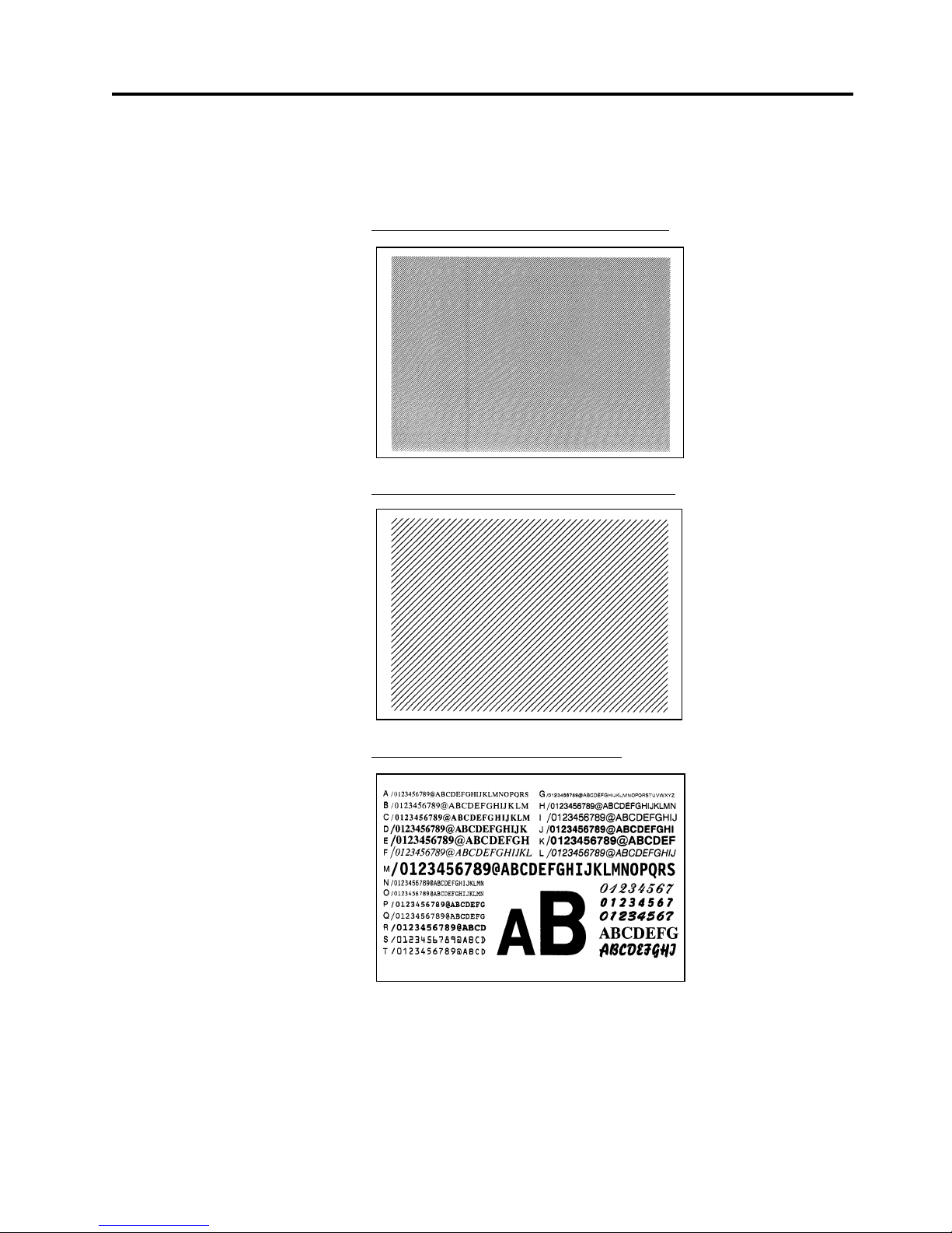
2. PRINTER SETUP
ENGLISH VERSION EO1-33036
2.10 Test Print
E2-17
2.10 Test Print (Cont.)
19.
When you have finished performing the test print operation, turn the
printer’s power OFF then back to ON and check that the LCD
Message Display shows ON LINE and that the ON LINE and
POWER LED lights are illuminated.
Sample of the slant line (1 dot) test print label
Sample of the slant line (3 dots) test print label
Sample of the character test print label
Page 86
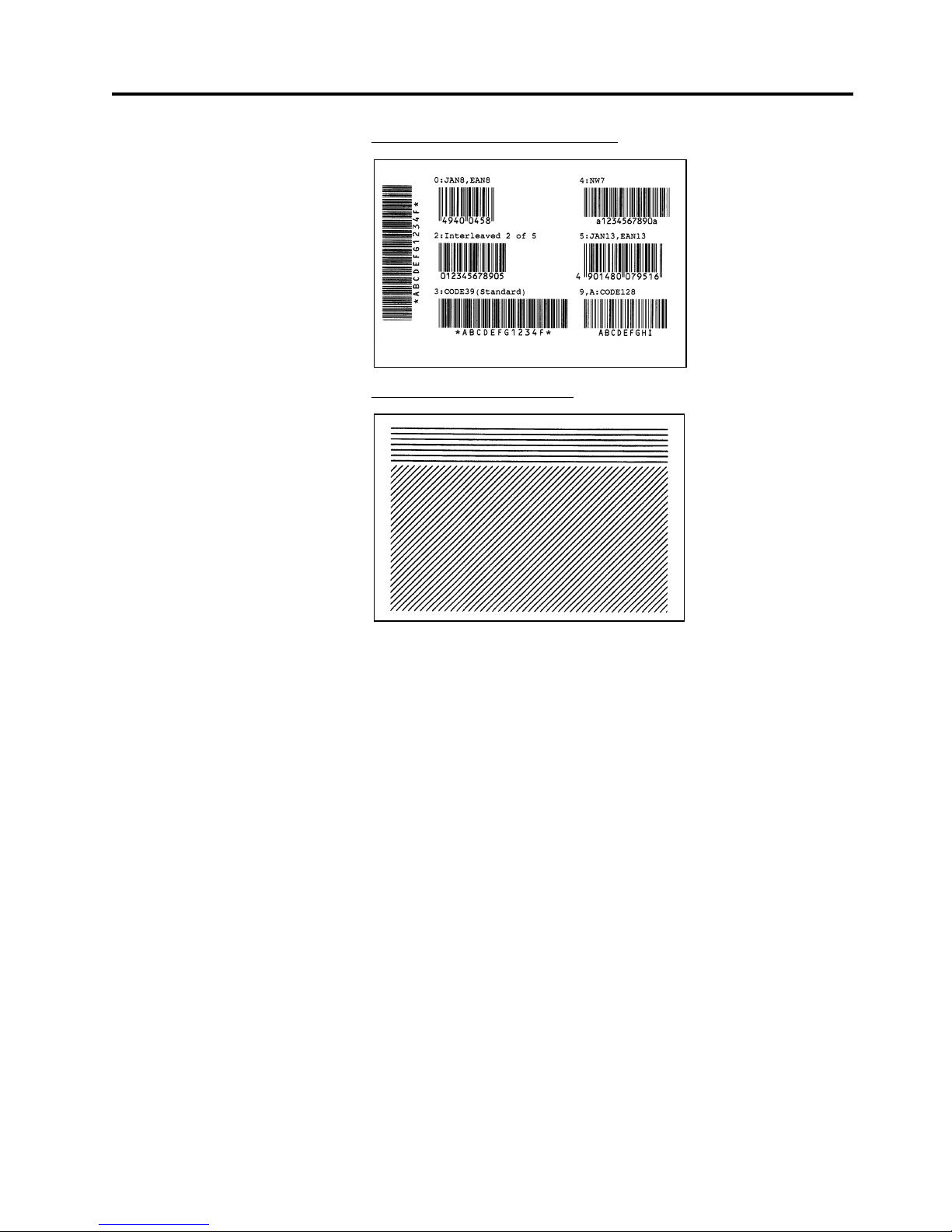
2. PRINTER SETUP
ENGLISH VERSION EO1-33036
2.10 Test Print
E2-18
2.10 Test Print (Cont.)
Sample of the bar code test print label
Sample of the factory test label
Page 87
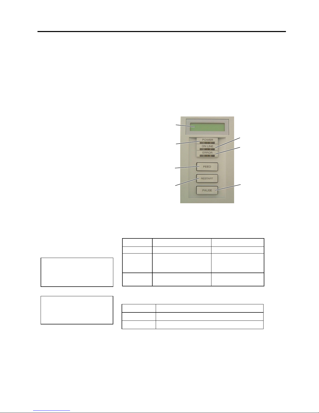
3. ON LINE MODE
ENGLISH VERSION EO1-33036
3.1 Operation Panel
E3- 1
3. ON LINE MODE
3.1 Operation Panel
This chapter describes usage of the keys on the Operation Panel in On
Line mode.
When the printer is in On Line mode and connected to a host computer,
the normal operation of printing images on labels or tags can be
accomplished.
•
The figure below illustrates the operation panel and key functions.
The LCD Message Display shows messages in alphanumeric characters
and symbols to indicate the printer’s current status. Up to 32 characters
can be displayed on two lines.
There are three LED lights on the operation panel.
LED Illuminates when… Flashes when…
POWER
The printer is turned on. -----
ON LINE
The printer is ready to
print.
The printer is
communicating with
your computer.
ERROR
Any error occurs with
the printer.
The ribbon is nearly
over. (See NOTE.)
There are three keys on the operation panel.
PAUSE
Used to stop printing temporarily.
RESTART
Used to restart printing.
FEED
Used to feed the media.
NOTE:
Use the
[RESTART]
key to
resume printing after a pause, or
after clearing an error.
LCD Message Display
ON LINE LED (Green)
ERROR LED (Red)
[PAUSE]
key
POWER LED
(Green)
[FEED]
ke
y
[RESTART]
ke
y
NOTE:
Flashes only when the Ribbon
N
ear End Detection function is
selected.
Page 88

3. ON LINE MODE
ENGLISH VERSION EO1-33036
3.2 Operation
E3- 2
3.2 Operation
3.3 Reset
When the printer is turned on, the “ON LINE” message appears on the
LCD Message Display. It is shown during standby or normal printing.
1.
The printer is turned on, standing by, or printing.
2.
If any error occurs during printing, an error message appears. The
printer stops printing automatically. (The number on the right side
shows the remaining number of media to be printed.)
3.
To clear the error, press the
[RESTART]
key. The printer resumes
printing.
4
. If the
[PAUSE]
key is pressed during printing, the printer stops
printing temporarily. (The number on the right side shows the
remaining number of media to be printed.)
5.
When the
[RESTART]
key is pressed, the printer resumes printing.
A reset operation clears the print data sent from the computer to the
printer, and returns the printer to an idle condition.
1.
The printer is turned on, standing by, or printing.
2.
To stop printing, or clear the data sent from the computer, press the
[PAUSE]
key. The printer stops printing.
3.
Press and hold the
[RESTART]
key for 3 seconds or longer.
4.
Press the
[PAUSE]
key. The data sent from the computer will be
cleared, and the printer returns to an idle condition.
21 /,1(
%6;7 9$
12 3$3(5
%6;7 9$
21 /,1(
%6;7 9$
3$86(
%6;7 9$
21 /,1(
%6;7 9$
NOTE:
I
f the
[RESTART]
key is held for
less than 3 seconds when the
p
rinter is in an error or pause
state, the printer restarts printing.
H
owever, when a communication
error or command error occurs,
the printer returns to an idle
condition.
21 /,1(
%6;7 9$
3$86(
%6;7 9$
21 /,1(
%6;7 9$
!5(6(7
Page 89

3. ON LINE MODE
ENGLISH VERSION EO1-33036
3.4 Dump Mode
E3- 3
3.4 Dump Mode
In Dump mode, any characters sent from the host computer will be
printed. Received characters are expressed in hexadecimal values. This
allows the user to verify programming commands and debug the
program.
For details, please refer to your nearest TOSHIBA TEC service
representative.
Page 90

4. MAINTENANCE
ENGLISH VERSION EO1-33036
4.1 Cleaning
E4- 1
4. MAINTENANCE
4.1 Cleaning
4.1.1 Print Head/Platen/
Sensors
This chapter describes how to perform routine maintenance.
To ensure the continuous high quality operation of the printer, you should
perform a regular maintenance routine. For high throughput it should be
done on a daily basis. For low throughput it should be done on a weekly
basis.
To maintain the printer performance and print quality, please clean the
printer regularly, or whenever the media or ribbon is replaced.
1.
Turn off the power and unplug the printer.
2.
Open the Top Cover.
3.
T urn the Head Lever to
Free
position, then release the Ribbon Shaft
Holder Plate.
4.
Open the Print Head Block.
5.
Remove the ribbon and media.
6.
Clean the Print Head Element with a Print Head Cleaner or a cotton
swab or soft cloth slightly moistened with alcohol.
7.
Wipe the Platen, Feed Roller, and Pinch Roller with a soft cloth
slightly moistened with alcohol. Remove dust or foreign substances
from the internal part of the printer.
8.
Wipe the Feed Gap Sensor and Black Mark Sensor with a dry soft
cloth.
WARNING!
1. Be sure to disconnect the
power cord before
performing maintenance.
Failure to do this may
cause an electric shock.
2. To avoid injury, be
careful not to pinch your
fingers while opening or
closing the cover and
print head block.
3. The print head becomes
hot immediately after
printing. Allow it to cool
before performing any
maintenance.
4. Do not pour water directly
onto the printer.
CAUTION!
1. Do not allow any hard
objects to touch the Print
Head or Platen, as this
may cause damage to
them.
2. Do not use any volatile
solvent including thinner
and benzene, as this
may cause discoloration
to the cover, print failure,
or breakdown of the
printer.
3. Do not touch the Print
Head Element with bare
hands, as static may
damage the Print Head.
4. Be sure to use the Print
Head Cleaner enclosed
with this printer. Failure
to do this may shorten
the Print Head life.
NOTE:
Please purchase the Print Head
Cleaner (P/No. 24089500013)
f
rom your authorised TOSHIBA
TEC service representative.
Print Head
Element
Print Head
Feed Roller
Platen
Pinch Roller
Black Mark Sensor/
Feed Gap Sensor
Page 91
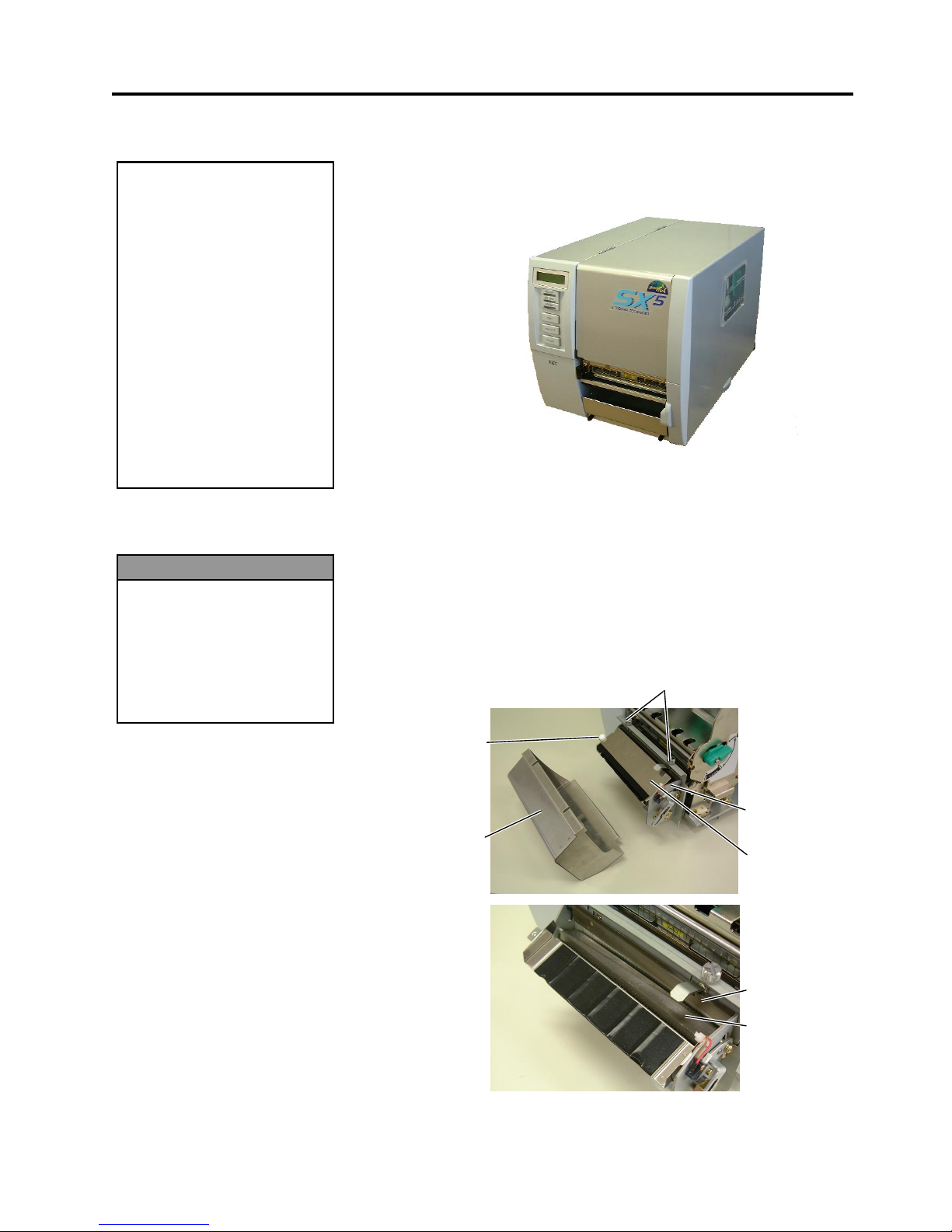
4. MAINTENANCE
ENGLISH VERSION EO1-33036
4.1 Cleaning
E4- 2
4.1.2 Covers and Panels
4.1.3 Optional Cutter Module
Wipe the covers and panels with a dry soft cloth or a cloth slightly
moistened with mild detergent solution.
The swing cutter and rotary cutter are available as an option. They are
both cleaned in the same way. When removing the Cutter Cover of the
rotary cutter unit, remove the screws from the bottom of the cover.
1.
Loosen the two screws to remove the Cutter Cover.
2.
Remove the Plastic Head Screw to detach the Media Guide.
3.
Remove the jammed paper.
4.
Clean the Cutter with a soft cloth slightly moistened with alcohol.
5.
Reassemble the Cutter Module in the reverse order of removal.
CAUTION!
1. DO NOT POUR WATER
directly onto the printer.
2. DO NOT APPLY cleaner
or detergent directly onto
any cover or panel.
3. NEVER USE THINNER
OR OTHER VOLATILE
SOLVENT on the plastic
covers.
4. DO NOT clean the panel,
covers, or the supply
window with alcohol as it
may cause them t o
discolour, loose their
shape or develop
structural weakness.
WARNING!
1. Be sure to turn the power
off before cleaning the
Cutter Module.
2. As the cutter blade is
sharp, care should be
taken not to injure
yourself when cleaning.
Swing Cutter
Cutter Unit
Screw
Fixed Cutter
Cutter Cover
Plastic Head
Screw
Media Guide
Page 92

4. MAINTENANCE
ENGLISH VERSION EO1-33036
4.2 Care/Handling of the Media and Ribbon
E4- 3
4.2 Care/Handling of the
Media and Ribbon
• Do not store the media or ribbon for longer than the manufacturer’s
recommended shelf life.
• Store media rolls on the flat end. Do not store them on the curved
sides as this might flatten that side causing erratic media advance and
poor print quality.
• Store the media in plastic bags and always reseal after opening.
Unprotected media can get dirty and the extra abrasion from the dust
and dirt particles will shorten the print head life.
• Store the media and ribbon in a cool, dry place. Avoid areas where
they would be exposed to direct sunlight, high temperature, high
humidity, dust or gas.
• The thermal paper used for direct thermal printing must not have
specifications which exceed Na
+
800 ppm, K+ 250 ppm and Cl- 500
ppm.
• Some ink used on pre-printed media may contain ingredients which
shorten the print head’s product life. Do not use labels pre-printed
with ink which contain hard substances such as carbonic calcium
(CaCO
3
) and kaolin (Al2O3, 2SiO2, 2H2O).
For further information, please contact your local distributor or your
media and ribbon manufacturers.
CAUTION!
Be sure to carefully review
and understand the Supply
Manual. Use only media
and ribbons that meet
specified requirements. Use
of non-specified media and
ribbons may shorten the
head life and result in
problems with bar code
readability or print quality.
All media and ribbons
should be handled with care
to avoid any damage to the
media, ribbons or printer.
Read the guidelines in this
section carefully.
Page 93
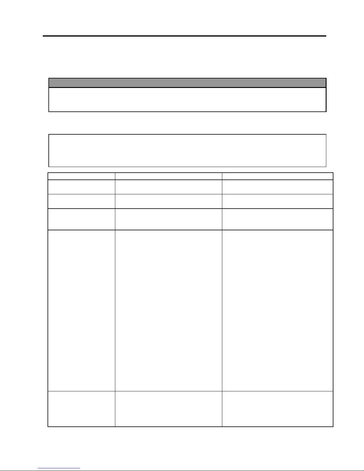
5. TROUBLESHOOTING
ENGLISH VERSION EO1-33036
5.1 Error Messages
E5- 1
5. TROUBLESHOOTING
This chapter lists the error messages, possible problems, and their solutions.
5.1 Error Messages
Error Messages Problems/Causes Solutions
HEAD OPEN
The Print Head Block is opened in
Online mode.
Close the Print Head Block.
HEAD OPEN ****
Feeding or printing has been attempted
with the Print Head Block open.
Close the Print Head Block. Then press
the
[RESTART]
key.
COMMS ERROR
A communication error has occurred. Make sure the interface cable is correctly
connected to the printer and the host, and
the host is turned on.
PAPER JAM ****
1. The media is jammed in the media
path. The media is not fed smoothly.
2.
A wrong Media Sensor is selected for
the media being used.
3.
The Black Mark Sensor is not
correctly aligned with the Black
Mark on the media.
4.
Size of the loaded media is different
from the programmed size.
5.
The Feed Gap Sensor cannot
distinguish the print area from a label
gap.
1.
Remove the jammed media, and clean
the Platen. Then reload the media
correctly. Finally press the
[RESTART]
key.
2.
Turn the printer off and then on. Then
select the Media Sensor for the media
being used. Finally resend the print
job.
3.
Adjust the sensor position. Then press
the
[RESTART]
key.
4.
Replace the loaded media with one
that matches the programmed size
then press the
[RESTART]
key, or
turn the printer off and then on, select
a programmed size that matches the
loaded media. Finally resend the print
job.
5.
Refer to Section 5.4 to set the
threshold. If this does not solve the
problem, turn off the printer, and call a
TOSHIBA TEC authorised service
representative.
CUTTER ERROR ****
(Only when the cutter
module is installed on
the printer.)
The media is jammed in the cutter. Remove the jammed media. Then press
the
[RESTART]
key. If this does not
solve the problem, turn off the printer, and
call a TOSHIBA TEC authorised service
representative.
N
OTES:
•
If an error is not cleared by pressing the
[RESTART]
key, turn the printer off and then on.
•
After the printer is turned off, all print data in the printer is cleared.
•
“****”
indicates the number of unprinted media. Up to 9999 (in pieces).
WARNING!
If a problem cannot be solved by taking the actions described in t his chapt er , do not attempt to
repair the printer. Turn off and unplug the printer, then contact an authorised TOSHIBA TEC servic
e
representative for assistance.
Page 94
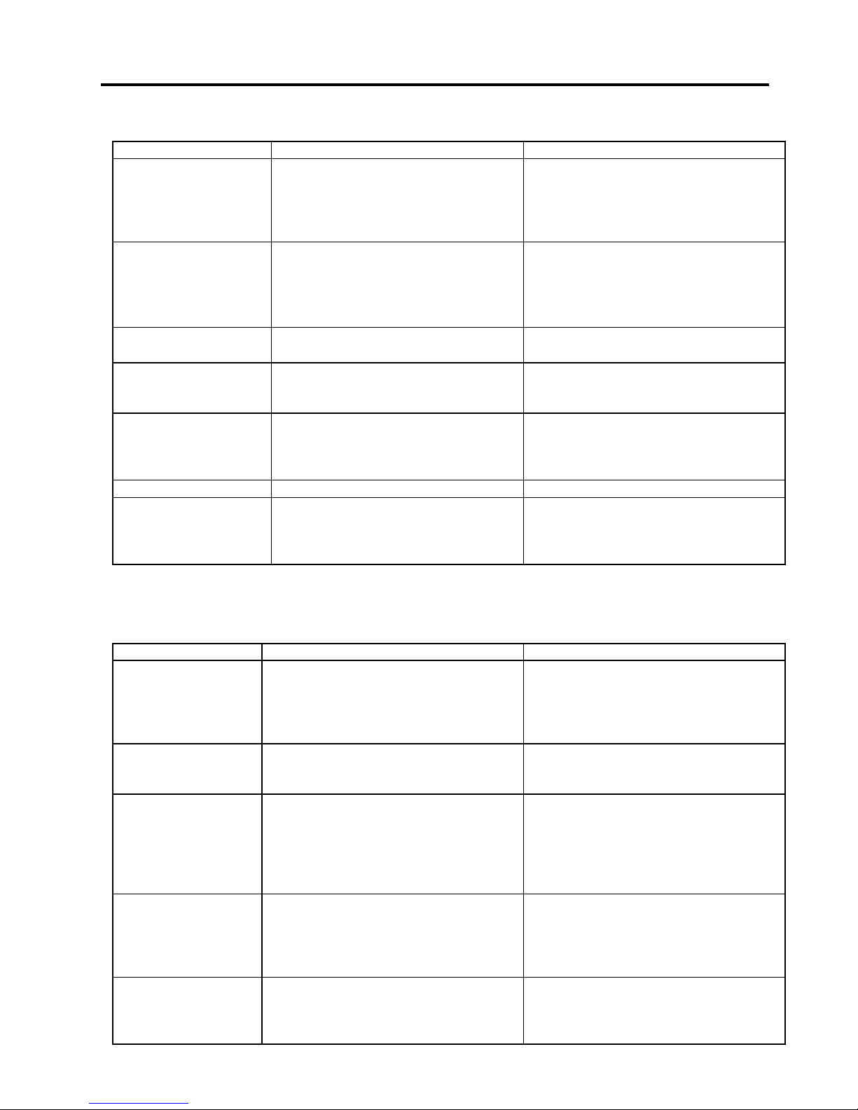
5. TROUBLESHOOTING
ENGLISH VERSION EO1-33036
5.2 Possible Problem s
E5- 2
5.1 Error Messages (Cont.)
Error Messages Problems/Cause Solutions
NO PAPER ****
1. The media has run out.
2. The media is not loaded properly.
3. The media is slack.
1. Load new media. Then press the
[RESTART]
key.
2. Reload the media correctly. Then
press the
[RESTART]
key.
3. Take up any slack in the media.
RIBBON ERROR ****
The ribbon is not fed properly.
Remove the ribbon, and check the status
of the ribbon. Replace the ribbon, if
necessary. If the problem is not solved,
turn off the printer, and call a TOSHIBA
TEC authorised service representative.
NO RIBBON ****
The ribbon has run out. Load a new ribbon. Then press the
[RESTART]
key.
REWIND FULL ****
The Built-In Rewinder Unit is full. Remove the backing paper from the Built-
In Rewinder Unit. Then press the
[RESTART]
key.
EXCESS HEAD TEMP
The Print Head has overheated. Turn off the printer, and allow it to cool
down (about 3 minutes). If this does not
solve the problem, call a TOSHIBA TEC
authorised service representative.
HEAD ERROR
There is a problem with the Print Head. Replace the Print Head.
Other error messages A hardware or software problem may
have occurred.
Turn the printer off and then on. If this
does not solve the problem, turn off the
printer again, and call a TOSHIBA TEC
authorised service representative.
5.2 Possible Problems
This section describes problems that may occur when using the printer, and their causes and solutions.
Possible Problems Causes Solutions
The printer will not
turn on.
1. The Power Cord is disconnected.
2. The AC outlet is not functioning
correctly.
3. The fuse has blown, or the circuit
breaker has tripped.
1. Plug in the Power Cord.
2. Test with a power cord from another
electric appliance.
3. Check the fuse or breaker.
The media is not fed. 1. The media is not loaded properly.
2. The printer is in an error condition.
1. Load the media properly.
2. Solve the error in the message display.
(See Section 5.1 for more detail.)
Nothing is printed on
the media.
1. The media is not loaded properly.
2. The ribbon is not loaded properly.
3. The print head is not installed
properly.
4. The ribbon and media are not
matched.
1. Load the media properly.
2. Load the ribbon properly.
3. Install the print head properly. Close
the Print Head Block.
4. Select an appropriate ribbon for the
media type being used.
The printed image is
blurred.
1. The ribbon and media are not
matched.
2. The Print Head is not clean.
1. Select an appropriate ribbon for the
media type being used.
2. Clean the print head using the Print
Head Cleaner or a cotton swab slightly
moistened with ethyl alcohol.
The cutter does not
cut.
1. The Cutter Cover is not attached
properly.
2. The media is jammed in the Cutter.
3. The cutter blade is dirty.
1. Attach the Cutter Cover properly.
2. Remove the jammed paper.
3. Clean the cutter blade.
Page 95

5. TROUBLESHOOTING
ENGLISH VERSION EO1-33036
5.3 Removing Jamm ed Media
E5- 3
5.3 Removing Jammed
Media
This section describes in detail how to remove jammed media from the
printer.
1.
Turn off and unplug the printer.
2.
Open the Top Cover.
3.
Turn the Head Lever to
Free
position, then open the Ribbon Shaft
Holder Plate.
4.
Open the Print Head Block.
5.
Remove the ribbon and media.
6.
Remove the jammed media from the printer. DO NOT USE any sharp
implements or tools as these could damage the printer.
7.
Clean the Print Head and Platen, then remove any further dust or
foreign substances.
8.
Paper jams in the Cutter Unit can be caused by wear or residual glue
from label stock on the cutter. Do not use non-specified media in the
cutter.
CAUTION!
Do not use any tool that may
damage the Print Head.
NOTE:
I
f you get frequent jams in the
cutter, contact a TOSHIBA TEC
authorised service
representative.
Print Head Block
Ribbon Shaft Holder Plate
Page 96

5. TROUBLESHOOTING
ENGLISH VERSION EO1-33036
5.4 Threshold Setting
E5- 4
5.4 Threshold Setting
To maintain a constant print position the printer uses the Transmissive
Sensor to detect the gap between labels by measuring the amount of
light passing through the media. When the media is pre-printed, the
darker (or more dense) inks can interfere with this process causing
paper jam errors. To get around this problem a minimum threshold can
be set for the sensor in the following way.
Threshold setting procedure
1.
Turn the power ON. The printer is in stand by mode.
2.
Load a pre-printed media roll.
3.
Press the
[PAUSE]
key.
4.
The printer enters the pause mode.
5.
Press and hold the
[PAUSE]
key for at least 3 seconds in the pause
state.
6.
The sensor type is displayed.
7.
Select the sensor to be adjusted by pressing the
[FEED]
key.
8.
Press and hold the
[PAUSE]
key until more than 1.5 labels (tags)
have been issued.
The media will continue to be fed until the
[PAUSE]
key is
released. (Threshold setting for the selected sensor is completed by
this operation.)
9.
Press the
[RESTART]
key.
10.
The printer is in stand-by.
11.
Send an issue command from the PC to the printer.
21 /,1(
%6;7 9$
3$86(
%6;7 9$
75$160,66,9(
%6;7 9$
5()/(&7,9(
%6;7 9$
75$160,66,9(
%6;7 9$
3$86(
%6;7 9$
21 /,1(
%6;7 9$
21 /,1(
%6;7 9$
NOTES:
1. If the
[PAUSE]
key is
released within 3 seconds
while in the pause state, the
paper will not feed.
2. Failure to feed more than
1.5 labels may result in an
incorrect threshold setting.
3. While the Print Head Block
is raised, the
[PAUSE]
key
does not work.
4. A paper end error cannot be
detected during paper feed.
5. Selecting the Transmissive
Sensor (for pre-printed
labels) within software
commands allows the
printer to detect the proper
print start position even
when using pre-printed
labels.
6. If using the Transmissive
Sensor and the printer
continues to print out of
position even after setting
the threshold, contact a
TOSHIBA TEC service
representative.
[FEED]
key
Black mark sensor
Feed gap sensor
Page 97
APPENDIX 1 SPECIFICATIONS
ENGLISH VERSION EO1-33036
A1.1 Printer
EA1- 1
APPENDIX 1 SPECIFICATIONS
Appendix 1 describes the printer specifications and supplies for use on the B-SX5T printer.
A1.1 Printer
The following is the printer specifications.
Model
Item
B-SX5T-TS10-QQ B-SX5T-TS10-QP
Supply voltage
Power consumption
During a print job
During standby
AC100 – 120V, 50/60 Hz±10%
1.7 A, 130 W maximum
0.19 A, 15 W maximum
AC220 – 240V, 50 Hz±10%
0.7 A, 124 W maximum
0.16 A, 16 W maximum
Operating temperature range
Relative humidity
Resolution
Printing method
Printing speed
Available media width (including
backing paper)
Effective print width (max.)
Issue mode
LCD Message display
Dimension (W × D × H)
Weight
Available bar code types
Available two-dimensional code
Available font
Rotations
Standard interface
5°C to 40°C (40°F to 104°F)
25% to 85% RH (no condensation)
12 dots/mm (306 dpi)
Thermal transfer or Thermal direct
76.2 mm/sec. (3 inches/sec.)
127.0 mm/sec (5 inches/sec.) For details, refer to Section A1.3.1.
203.2 mm/sec (8 inches/sec.)
30.0 mm to 140.0 mm (1.2 inches to 5.5 inches)
128.0 mm (5 inches)
Batch
Strip
Cut (Cut mode is enabled only when the optional Cutter Module is
installed.)
16 characters × 2 lines
291 mm × 460 mm × 308 mm (11.5” × 18.1” × 12.1”)
44.1 lb (20 kg) (Media and ribbon are not included.)
JAN8, JAN13, EAN8, EAN8+2 digits, EAN8+5 digits,
EAN13, EAN13+2 digits, EAN13+5 digits, UPC-E, UPC-E+2 digits,
UPC-E+5 digits, UPC-A, UPC-A+2 digits, UPC-A+5 digits, MSI,
ITF, NW-7, CODE39, CODE93, CODE128, EAN128, Industrial 2 to
5, Customer Bar Code, POSTNET, KIX CODE, RM4SCC (ROYAL
MAIL 4STATE CUSTOMER CODE), RSS14
Data Matrix, PDF417, QR code, Maxi Code, Micro PDF417, CP Code
Times Roman (6 sizes), Helvetica (6 sizes), Presentation (1 size),
Letter Gothic (1 size), Prestige Elite (2 sizes), Courier (2 sizes), OCR
(2 types), Gothic (1 size), Outline font (4 types), Price font (3 types)
0°, 90°, 180°, 270°
Serial interface (RS-232C)
Parallel interface (Centronics)
Expansion I/O interface
Optional interface PCMCIA interface (B-9700-PCM-QM)
USB interface (B-9700-USB-QM)
LAN interface (B-9700-LAN-QM)
N
OTES:
•
Data Matrix
TM
is a trademark of International Data Matrix Inc., U.S.
•
PDF417
TM
is a trademark of Symbol Technologies Inc., US.
•
QR Code is a trademark of DENSO CORPORATION.
•
Maxi Code is a trademark of United Parcel Service of America, Inc., U.S.
Page 98
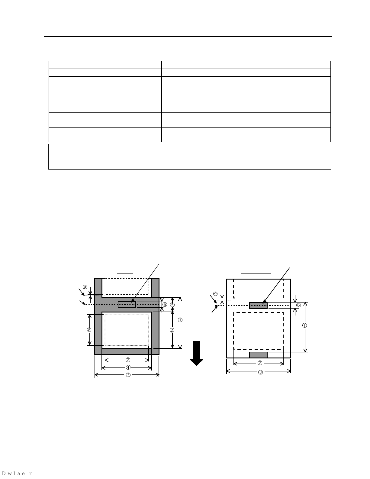
APPENDIX 1 SPECIFICATIONS
ENGLISH VERSION EO1-33036
A1.2 Options
EA1- 2
A1.2 Options
Option Name Type Description
Swing cutter module B-4205-QM A stop and cut swing cutter.
Rotary cutter module B-8204-QM Rotary cutter
PCMCIA interface
board
B-9700-PCM-QM This board enables the use of the following PCMCIA cards.
LAN card:
3 COM 3CCE589ET (recommended)
ATA card: Conforming to PC card ATA standard
Flash memory card: 1MB and 4MB cards (See Section 2.9.)
Built-in LAN
interface board
B-9700-LAN-QM This board enables the printer to be used in a LAN network.
USB interface board B-9700-USB-QM Installing this board enables a connection to a PC which has a
USB interface.
A1.3 Media
Please make sure that the media being used is approved by TOSHIBA TEC. The warranty does not apply when a
problem is caused by using media that is not approved by TOSHIBA TEC.
For information regarding TOSHIBA TEC approved media, please contact a TOSHIBA TEC authorised service
representative.
A1.3.1 Media Type
Two types of media can be loaded for this thermal transfer and direct thermal printer: label or tag. The table
below shows size and shape of the media available for this printer.
N
OTE:
To purchase the optional kits, please contact the nearest authorised TOSHIBA TEC representative or TOSHIBA
TEC Head Quarters.
Label
Tag paper
Cut position
Cut position
Stop
position
Stop
position
Feed Direction
Black Mark
(on reverse side)
Black Mark
(on reverse side) Refer to
NOTE 3 below.
h
e
c
e
g
h
c
d
i
i
k
k
f
j
Page 99

APPENDIX 1 SPECIFICATIONS
ENGLISH VERSION EO1-33036
A1.3 Media
EA1- 3
A1.3.1 Media Type (Cont.)
[Unit: mm]
Cut mode
Label dispensing mode
Item
Batch mode Strip mode
Rotary cutter
Swing cutter
Label 10.0 – 1500.0 25.4 – 1500.0
38.0 - 1500.0
38.0 – 1500.0
c
Media pitch
Tag 10.0 – 1500.0 ----
3”/sec., 5”/sec.: 30.0 – 1500.0
8”/sec.: 38.0 – 1500.0
25.4 – 1500.0
d
Label length 8.0 – 1498.0 23.4 – 1498.0
25.0 – 1494.0
25.0 – 1494.0
(*1)
e
Width including backing paper
(See NOTE 5.)
30.0 – 140.0 50.0 – 140.0 30.0 – 112.0 30.0 – 140.0
f
Label width (See NOTE 5.) 27.0 – 137.0 47.0 – 137.0 27.0 – 109.0 27.0 – 137.0
g
Gap length 2.0 – 20.0 6.0 – 20.0
h
Black mark length (Tag paper) 2.0 – 10.0
i
Effective print width 10.0 – 128.0
Label 6.0 – 1496.0 21.4 – 1496.0
23.0 - 1492.0
23.0 – 1492.0
j
Effective print length
Tag 8.0 – 1498.0
----
3”/sec., 5”/sec.: 28.0 – 1496.0
8”/sec.: 36.0 – 1496.0
23.0 – 1496.0
k
Print speed up/slow down area 1.0
Label 0.13 – 0.17
Thickness
Tag 0.15 – 0.29
Maximum effective length for on the fly issue 749.0
Maximum outer roll diameter Ø200
Roll direction Inside
Inner core diameter Ø76.2±0.3
A1.3.2 Detection Area of the Transmissive Sensor
The Transmissive Sensor is movable from the centre to the left edge of media.
The Transmissive Sensor detects a gap between labels, as illustrated below.
<Label>
N
OTES:
1. To ensure print quality and print head life use only TOSHIBA TEC specified media.
2. The media length specifications for use of the cutter are:
*1: When issuing a label using the swing cutter, label length should be 35.0 mm – (Gap length/2).
3. When marking black marks on the label rolls, they should be marked at the gaps.
4. “On the fly issue” means that the printer can feed and print without stopping between labels.
5.
There are restrictions in use of the media which is narrower than 50 mm. For details, refer to TOSHIBA TEC
service representative
.
Sensor position
Area to be detected.
Centre of media
Print side
Min. 12 mm
Label
Gap
Label
Min. 2.0 mm
(Min. 6.0 mm when using
the cutter module.)
Sensor is movable
within this range.
Media feed direction
Page 100
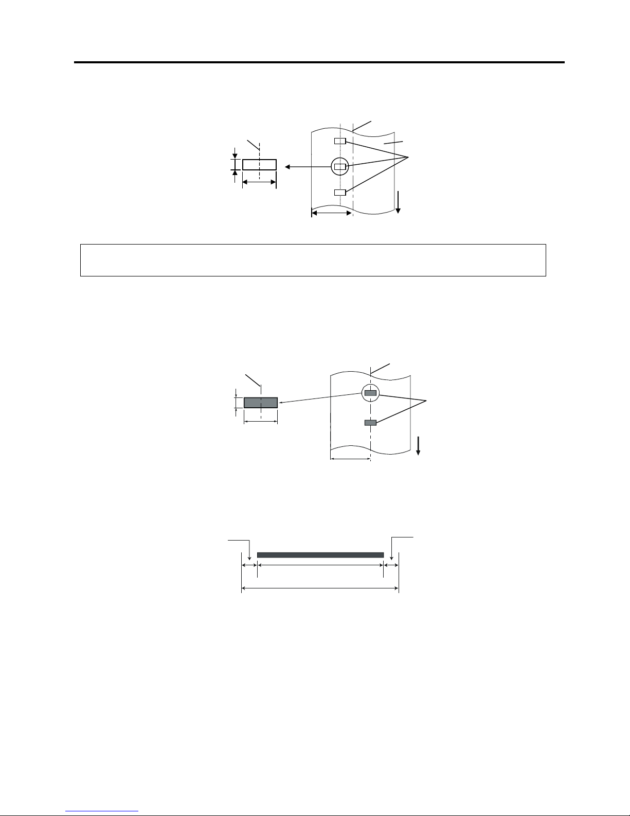
APPENDIX 1 SPECIFICATIONS
ENGLISH VERSION EO1-33036
A1.3 Media
EA1- 4
A1.3.2 Detection Area of the Transmissive Sensor (Cont.)
<Tag paper with square holes>
A1.3.3 Detection Area of the Reflective Sensor
The Reflective Sensor is movable from the centre to the left edge of media.
The reflection factor of the Black Mark must be 10% or lower with a waveform length of 950 nm.
The Reflective Sensor should be aligned with the centre of the Black Mark.
A1.3.4 Effective Print Area
The figure below illustrates the relation between the head effective print width and media width.
Sensor should be positioned at
the centre of the black mark.
Centre of media
Min. 12 mm
Media feed direction
Min. 2.0 mm
Sensor is movable
within this range.
6.0
mm
140 mm (Max. media width)
128.0 mm±0.2
(Head Effective Print Range)
Out of print range
Out of print range
6.0
mm
Detecting the black
marks on the back.
Sensor position
Centre of media
Min. 12 mm
Media feed direction
Min. 2.0 mm
Sensor is movable
within this range.
Square holes
(Round holes are not acceptable.)
Print side
N
OTE:
R
ound holes are not acceptable.
 Loading...