

Page 1

TEC Thermal Printer
B-870 SERIES
Maintenance Manual
Document No. EM18-33013
Original Jan., 1995
(Revision )
PRINTED IN JAPAN
Page 2

(Revision Date: Jul. 26 ’99)
TABLE OF CONTENTS
Page
1. UNPACKING ...................................................................................................... 1- 1
1.1 PROCEDURES...........................................................................................1- 1
1.2 CHECKS ..................................................................................................... 1- 1
2. MAJOR UNIT REPLACEMENT.......................................................................... 2- 1
2.1 REPLACING THE CPU PC BOARD........................................................... 2- 2
2.2 REPLACING THE PS UNIT ........................................................................ 2- 4
2.3 REPLACING THE STEPPING MOTORS AND BELTS .............................. 2- 5
2.4 REPLACING THE RIBBON MOTORS........................................................2- 6
2.5 REPLACING THE SOLENOID....................................................................2- 6
2.6 REPLACING THE PRINT HEAD ................................................................ 2- 8
2.7 REPLACING THE PLATEN ........................................................................ 2- 9
2.8 REPLACING THE ROLLER BELT AND FEED ROLLER .......................... 2-10
2.9 REPLACING THE MEDIA SENSORS ....................................................... 2-12
2.10PERIODIC PARTS REPLACEMENT......................................................... 2-13
EM18-33013
3. INSTALLATION PROCEDURE FOR OPTIONAL EQUIPMENT ........................ 3- 1
3.1 HIGH SPEED PC INTERFACE BOARD (B-4800-PC-QM)......................... 3- 1
3.2 CUTTER MODULE (B-4208-QM) ............................................................... 3- 3
3.3 MEMORY MODULE.................................................................................... 3- 5
3.4 STRIP MODULE (B-4908-H-QM) ............................................................... 3- 6
3.5 STABILIZER KIT ......................................................................................... 3- 7
4. MECHANISM DESCRIPTION ............................................................................ 4- 1
4.1 CUTTER DRIVE.......................................................................................... 4- 1
5. TROUBLESHOOTING........................................................................................ 5- 1
6. DIAG. TEST OPERATION.................................................................................. 6- 1
7. PROGRAM DOWN LOAD .................................................................................. 7- 1
7.1 FLOPPY DISK............................................................................................. 7- 1
7.2 SETUP ........................................................................................................ 7- 1
7.3 DOWN LOAD PROCEDURE ...................................................................... 7- 2
7.4 ERROR CODE............................................................................................ 7- 3
CAUTION:
1. This manual may not be copied in whole or in part without prior written permission of
TOSHIBA TEC.
2. The contents of this manual may be changed without notification.
3. Please refer to your local Authorized Service representative with regard to any queries
you may have in this manual.
Copyright © 1999
by TOSHIBA TEC CORPORATION
All Rights Reserved
570 Ohito, Ohito-cho, Tagata-gun, Shizuoka-ken, JAPAN
Page 3
1. UNPACKING
1. UNPACKING
1.1 PROCEDURE
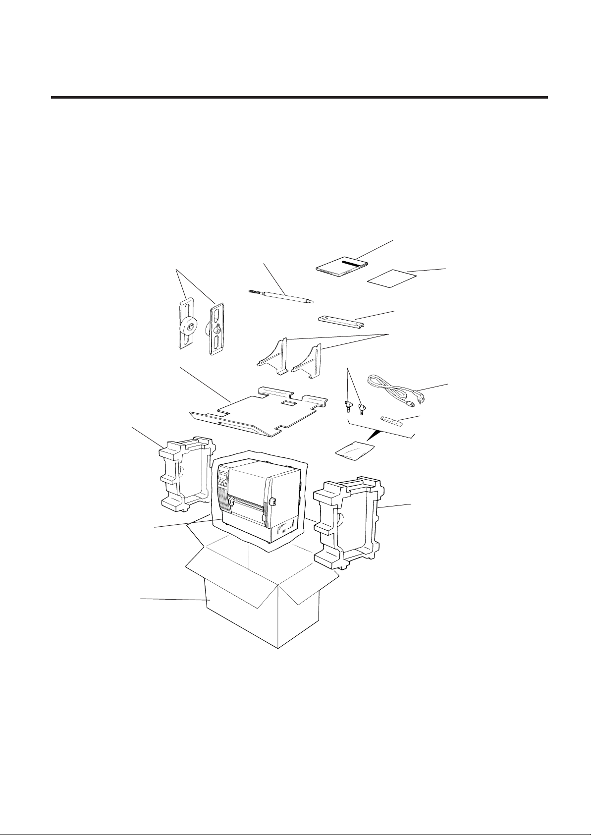
1) Open the carton.
2) Unpack the accesories from the carton
3) Unpack the side pads (L)/(R) and the printer from the carton.
EM18-33013
1.1 PROCEDURE
4) Place the printer on a level surface.
Holder Shaft
Left/Right Side Holders
Accessory Board
Side Pad (L)
Owner’s Manual
Unpacking
Procedure
Holder Base
Media
Holder
Thumbscrew (M-4x6)
Power Cord
Print Head Cleaner
Side Pad (R)
Thermal printer
Carton
1.2 CHECKS
1) Check for damage or scratches on the machine.
2) Confirm that none of the accessories are missing.
NOTE: Keep the carton and side pads for later transport.
1-1
Fig. 1-1
Page 4
2. MAJOR UNIT REPLACEMENT
2. MAJOR UNIT REPLACEMENT
EM18-33013
2. MAJOR UNIT REPLACEMENT
WARNING!
Disconnect power cord before replacing important parts.
CAUTION:
1. NEVER separate the ribbon motors from the attaching plate (bracket), because doing so will
change their adjustment. (See Fig. 2-8)
2. NEVER remove the two screws painted red on the side of the print block. (See Fig. 2-11)
3. NEVER remove screws unless directed to do so in this manual. Removing screws may change
pre-set adjustments.
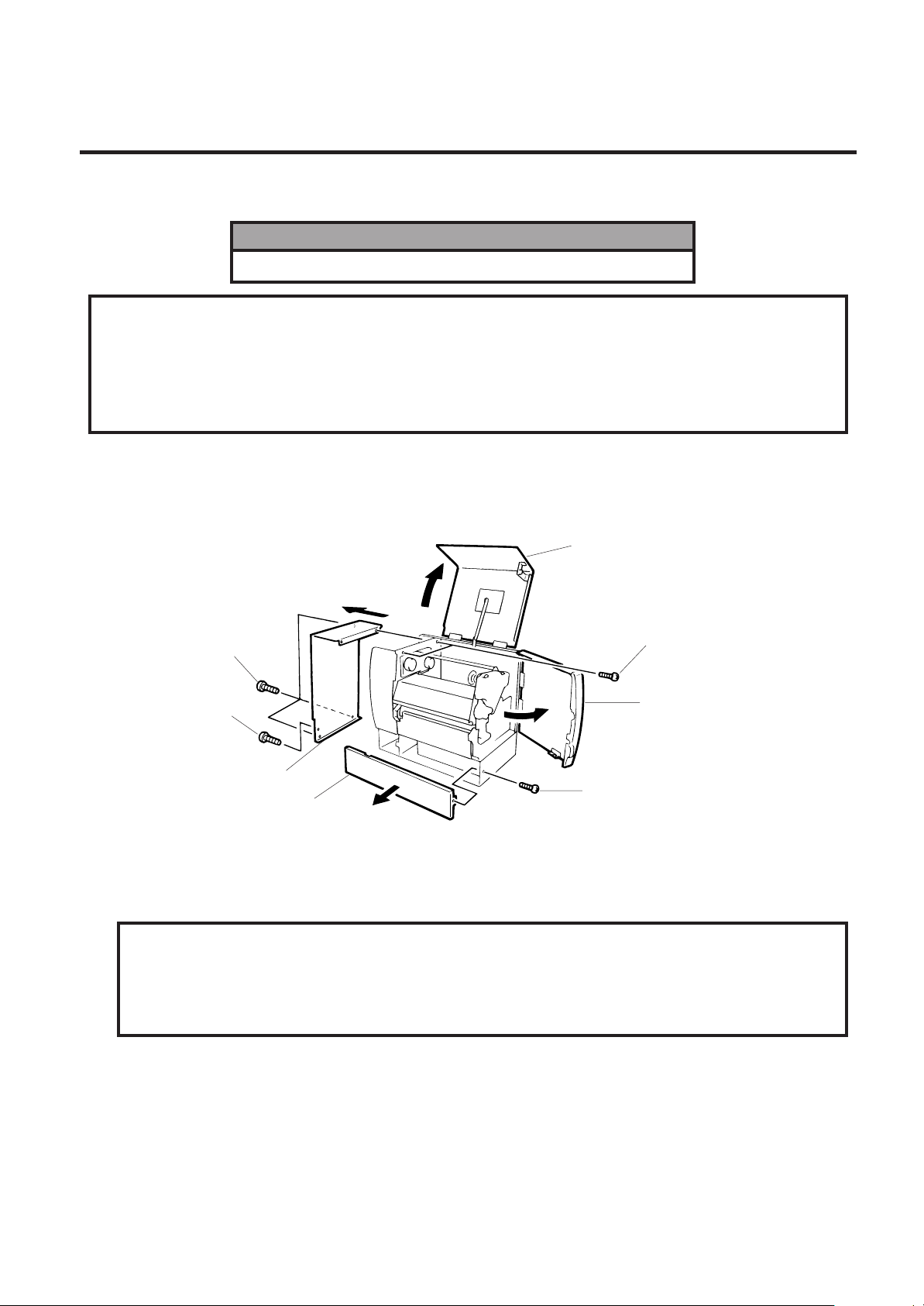
1) Turn the power off.
2) Open the right side and top covers.
3) Remove the six screws (FL-4x6, B-4x6 and B-3x8) to detach the left side cover.
4) Remove the (B-4x6) screw to remove the bottom plate.
Top Cover
Screw (B-4x6)
Screw (B-3x8)
Left Side Cover
Bottom Plate
Screw (B-3x8)
Screw (FL-4x6)
Right Side Cover
Fig. 2-1
NOTE: Instructions to open the top and right side covers and to remove the left side cover are omitted
from each removal/installation procedure provided below.
■ Lubrication
CAUTION:
1. Lubrication: During parts replacement
2. Kinds of oil: FLOIL G-488: 1 Kg can. (Parts No. 19454906001).
3. Do not spray the inside of the printer with lubricants. Unsuitable oil can damage the
mechanism.
All machines are generally delivered in their best condition. Efforts shoud be made to keep them that
way. Lack of oil, or the presence of debris or dust, may cause an unexpected failure. To maintain
in optimal operating condition, periodically clean the machine and apply the proper kinds of oil to each
part in which librication is needed.
Although the frequency of lubrication varies according to how often the machine is used, as a
minimum it is necessary to lubricate before any part becomes dry. It is also necessary to wipe off
excessive oil or it will collect dirt.
2-1
Page 5
2. MAJOR UNIT REPLACEMENT
2.1 REPLACING THE CPU PC BOARD
2.1 REPLACING THE CPU PC BOARD
CAUTION:
Replace only with the same type and rated fuse for continued protection against risk of fire.
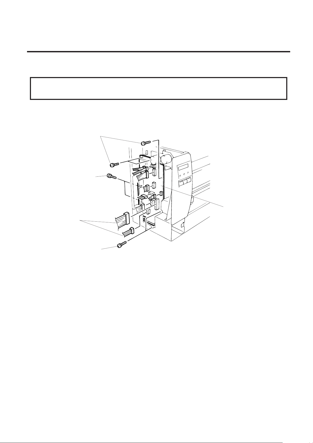
1) Detach the 11 connectors from the CPU PC board.
2) Remove the 7 screws (SM-3x5B and FL-3x5) to detach the CPU PC board.
Screw (SM-3x5B)
Screw (FL-3x5)
EM18-33013
CPU PC Board
Connector
Screw (SM-3x5B)
NOTE: Be sure to support the CPU PC board when detaching the connectors.
3) Replace the CPU PC board and reassemble in the reverse order of removal.
Fig. 2-2
2-2
Page 6
2. MAJOR UNIT REPLACEMENT
2.1 REPLACING THE CPU PC BOARD
(Revision Date Mar. 15 ’96)
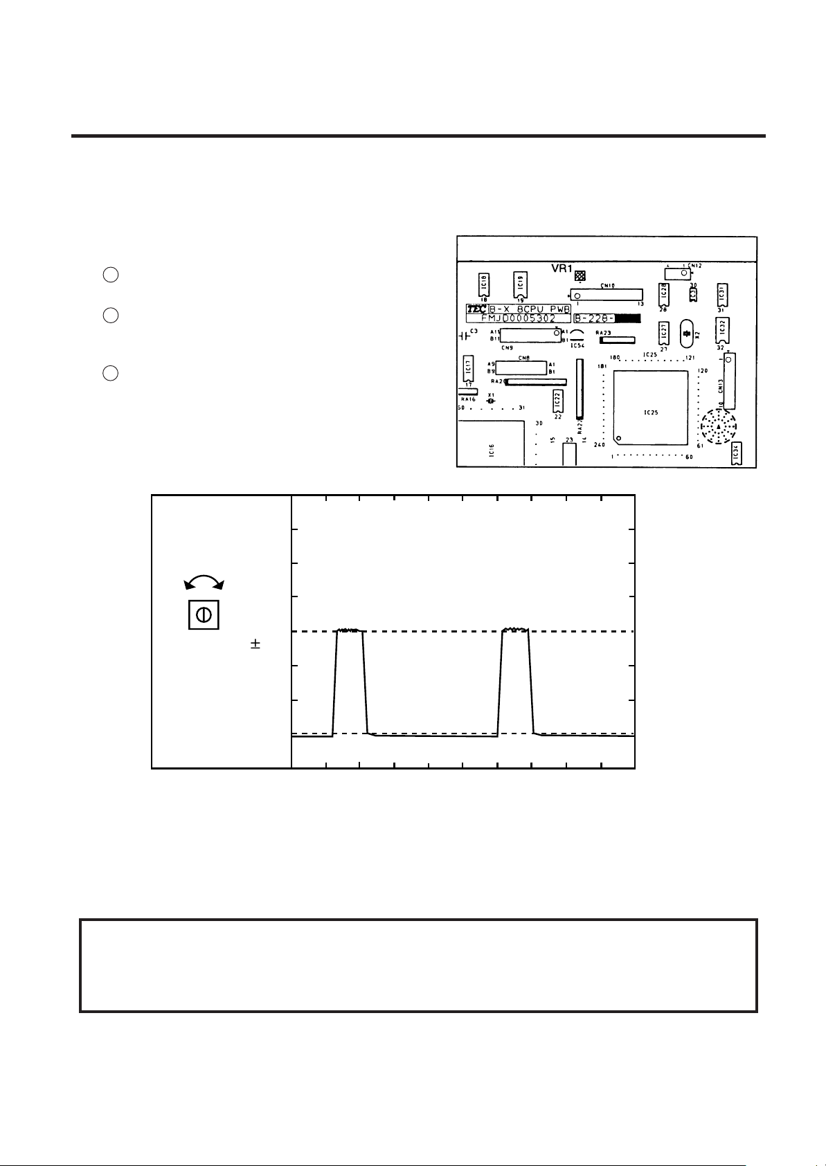
4) Adjust the ribbon end sensor.
After replacing the CPU PC board or changing ribbon type, be sure to adjust the ribbon end
sensor in the following procedure with the ribbon being used.
NOTE: Use TOSHIBA TEC-approved ribbons.
1 Set the ribbon so that the ribbon end sensor
can detect the ribbon, Turn the power on.
2 Turn the VR1 so that the voltage between Pin
1 (GND) and Pin 7 of CN10 is 3.0 ± 0.2 V as
measured with an oscilloscope.
3 Turn the power off and mount the left side
cover and top cover.
Fig. 2-3
EM18-33013
Range : 1V / 0.2 m sec.
Voltage
0.2V
3.0
VR1
GND
Fig. 2-4
5) Adjust the black mark sensor.
Refer to page 6-40 for the adjustment procedure for the black mark sensor which is adjusted by key
entries in system mode.
6) Adjust the feed gap sensor.
Refer to page 6-41 for the adjustment procedure for the feed gap sensor which is adjusted by key
entries in system mode.
CAUTION:
Be careful when replacing the CPU PC board, since a non-resettable counter (IC32) is installed on
thisboard. (Refer to Section 6.2.1 Maintenance Counter Printing.)If this counter should be reset,
replace IC32.
2-3
Page 7
2. MAJOR UNIT REPLACEMENT
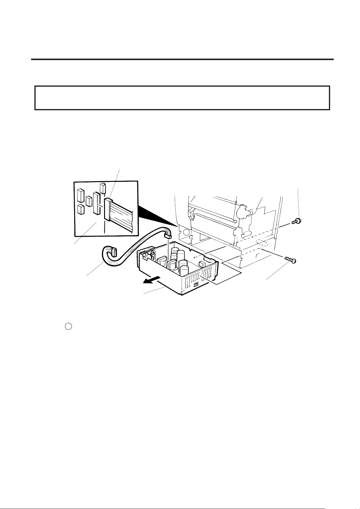
2.2 REPLACING THE PS UNIT
EM18-33013
2.2 REPLACING THE PS UNIT
CAUTION:
Replace only with the same type and rated of fuse for continued protection against risk of fire.
1) Detach all connectors from the CPU PC board.
2) Remove the two screws (FL-4 x 6) to detach the PS unit. Pushing the AC power inlet from behind
will ease the removal of the PS unit.
3) Disconnect the PS cable from the PS unit.
Connecter
Screw (FL- 4x6)
A
CPU PC Board
PS Cable
Screw (FL- 4x6)
PS Unit
Fig. 2-5
4) Replace the PS unit and reassemble in the reverse order of removal. Insert the PS cable into the
notch A .
2-4
Page 8
2. MAJOR UNIT REPLACEMENT
2.3 REPLACING THE STEPPING MOTOR
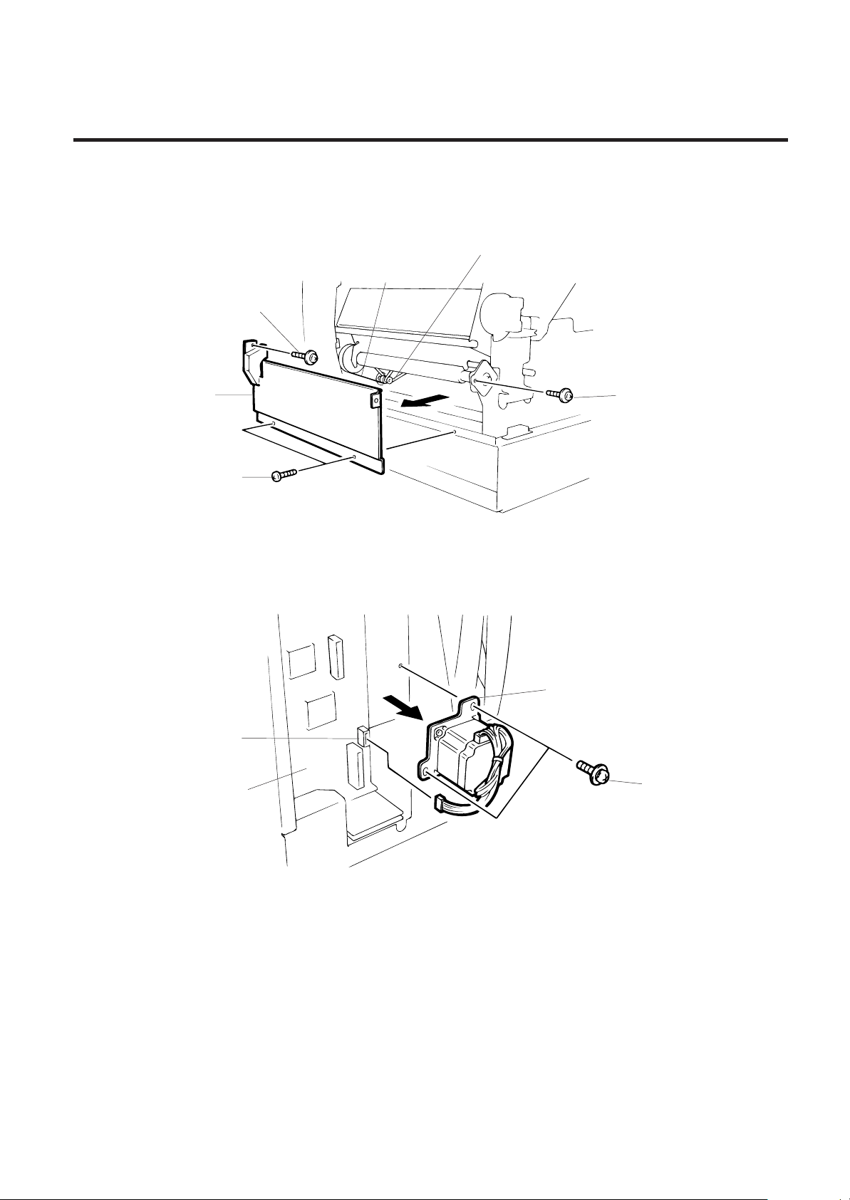
1) Remove the 4 screws (FL-4x6) to detach the front plate.
Platen Belt
Screw (FL-4x6)
EM18-33013
2.3 REPLACING THE STEPPING MOTOR
Feed Roller Belt
Front Plate
Screw (FL-4x6)
Screw (FL-4x6)
Fig. 2-6
2) Disconnect the cable from CN14 on the CPU PC board.
3) Remove the two screws (SM-4x10C), take the two belts off the pinion gear, and remove the stepping
motor.
Stepping Motor
CN14
CPU PC Board
Screw (SM-4x10C)
Fig. 2-7
4) When replacing the stepping motor, place the platen belt around the pinion gear first, then the feed
roller belt, so that the partition is positioned between the two belts. Press down on the stepping motor
with 3.5 Kg ± 300 g force and secure it so the platen belt and feed roller belt have no slack, are
engaged ,and evenly tense.
5) Reassemble in the reverse order of removal.
2-5
Page 9
2. MAJOR UNIT REPLACEMENT
2.4 REPLACING THE RIBBON MORTOR
EM18-33013
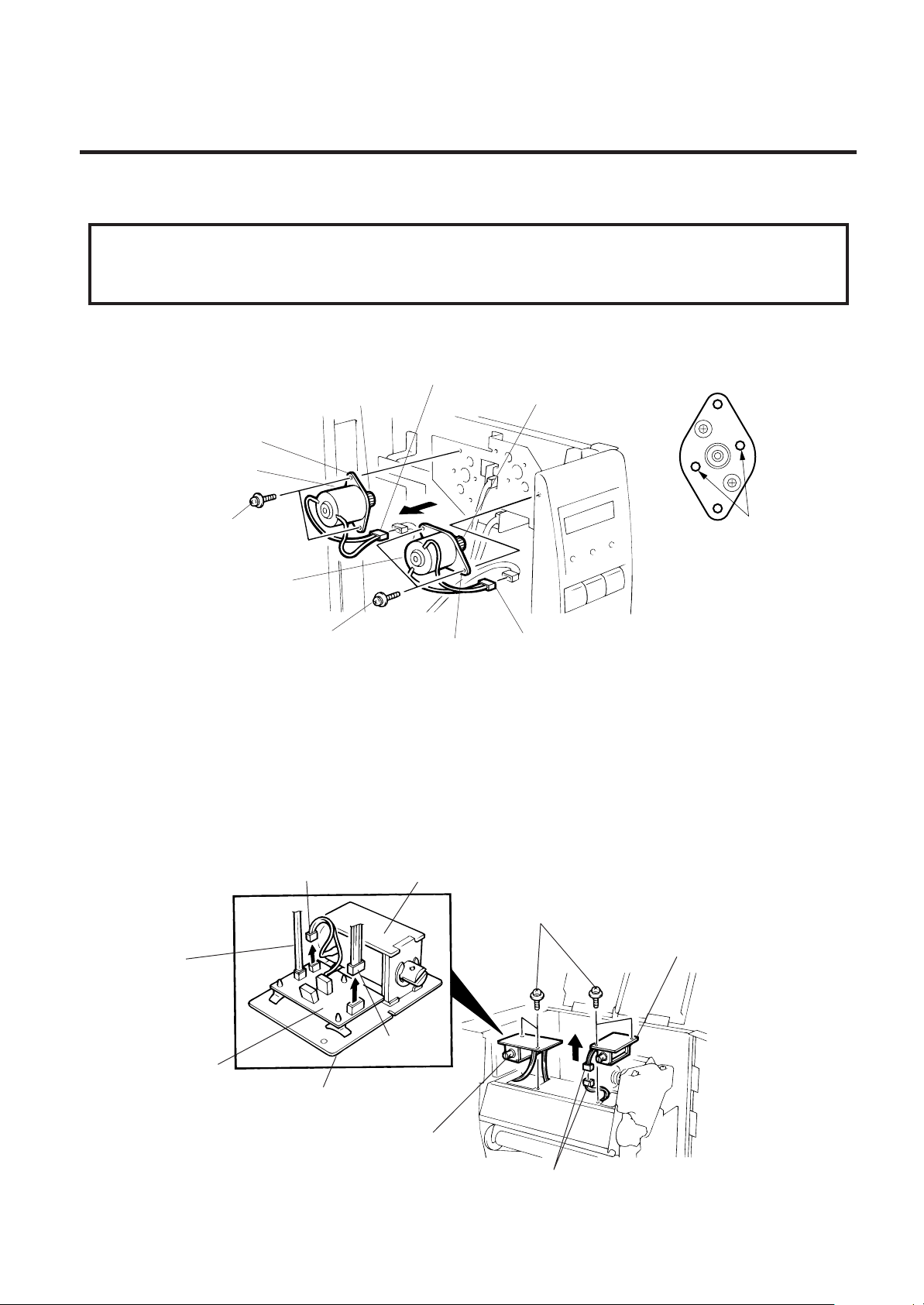
2.4 REPLACING THE RIBBON MOTORS
CAUTION:
NEVER separate the ribbon motor from the attaching plate because doing so will change their
adjustment.
1) Remove the CPU PC board. (Refer to section 2.1.)
2) Detach the connector and remove the two SM-3x5B screws to detach the ribbon motors.
Connector
FLOIL G-488
Attaching Plate
Ribbon Motor
(Red)
FLOIL G-488
Screw (SM-3x5B)
Riboon Motor
Screw (SM-3x5B)
Attaching Plate
Connector
(Black)
Dowels
Fig. 2-8
3) Replace the ribbon motors, then align the dowels to attach the ribbon motors. Reassemble in the
reverse order of removal.
2.5 REPLACING THE SOLENOID
NOTE: This procedure can be done without removing the left side cover.
1) Remove the two SM-4x8B screws, detach the connectors, and remove the solenoid unit (R).
2) Remove the two SM-4x8B screws, disconnect the cables from CN1, CN2 and CN3 on the RSV PC
board and detach the solenoid unit (L).
CN1 (Solenoid L)
CN2
(Solenoid R)
Solenoid
Screw (SM-4x8B)
Solenoid Unit (R)
RSV PC Board
CN3
Solenoid Attaching Plate
Solenoid Unit (L)
Fig. 2-9
Connecter
2-6
Page 10
2. MAJOR UNIT REPLACEMENT
(Revision Date Aug. 18 ’95)
2.5 REPLACING THE SOLENOID
EM18-33013
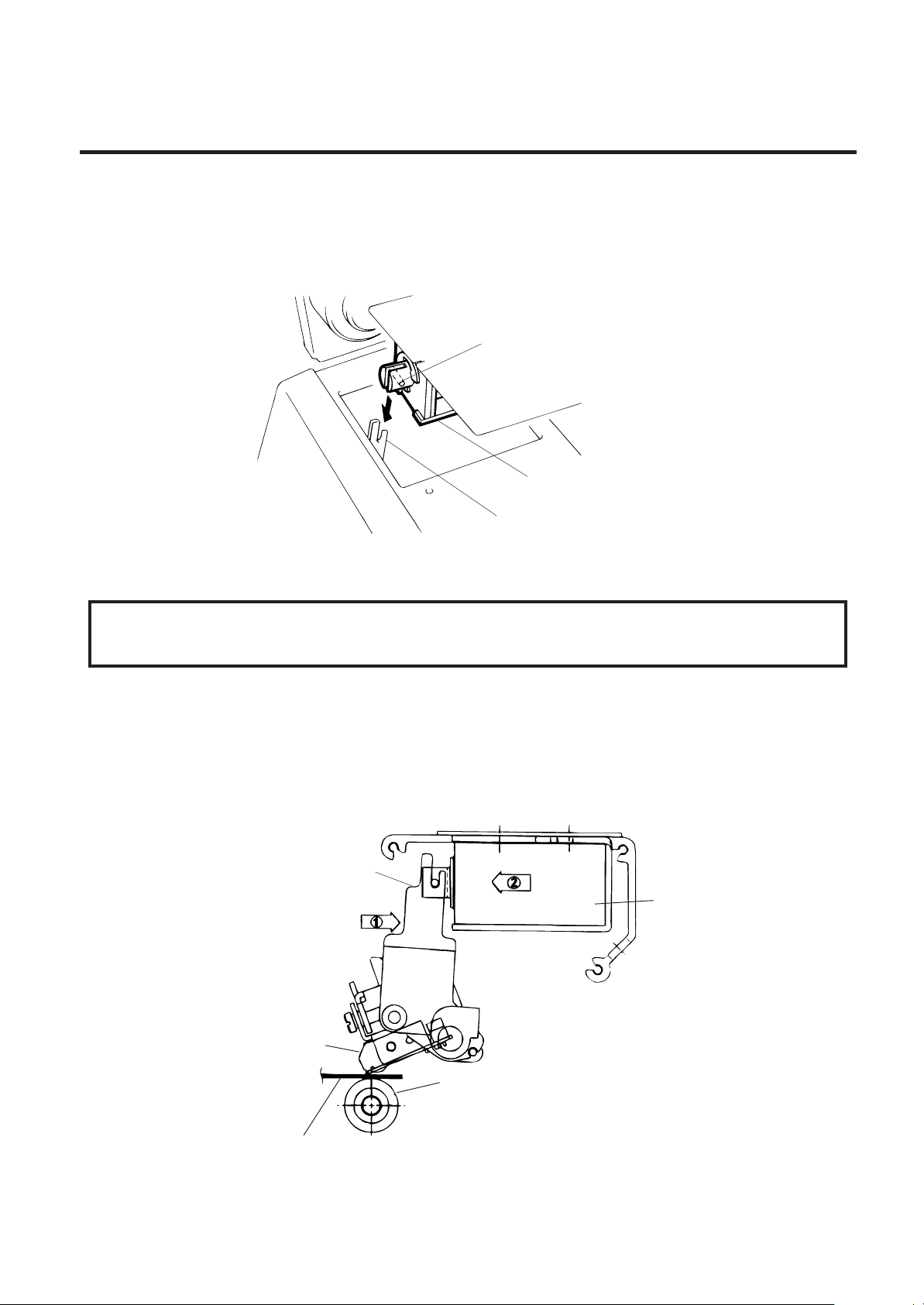
3) Remove the two SM-3 x 6B screws each from the solenoid units (L) and (R) to detach the solenoid.
4) Replace the solenoid and attach it to the solenoid attaching plate. Be careful of the differences in
length of the solenoid cables when installing the solenoid.
5) Assemble the solenoid unit so that the head up link engages the spring pin.
Spring Pin
Solenoid
Head Up Link
Fig. 2-10
NOTE: Make sure to remove any dust that appears during removal or installation because it may affect
the print quality.
CAUTION:
Take care to orient the screws so that they are vertically aligned with the solenoid attaching plate.
6) Insert piled 10 pieces of tag paper of 8 inches (203.2 mm) in width, 0.16 mm in thickness (I-BESTS is recommended) between the print head and the platen. Then turn the head lever to the LOCK
position.
7) Press and hold the link against the solenoid, and then press and fit the solenoid unit sungly to the
link. Secure the solenoid unit with the screws.
8) Reassemble in the reverse order of removal.
Link
Press
Press
Solenoid Unit
Print Head
Paper Thickness: 1.6 mm
Platen
Fig. 2-11
2-7
Page 11

2. MAJOR UNIT REPLACEMENT
2.6 REPLACING THE PRINT HEAD
2.6 REPLACING THE PRINT HEAD
CAUTION:
1. NEVER touch the element when handling the print head.
2. NEVER touch the connector pins to avoid damage to the print head by static electricity.
3. NEVER remove the two screwws painted red on the side of the print block.
NOTE: This procedure can be done without removing the left side cover.
1) Remove the two (B-4x4) screws to detach the head cover plate.
2) Pull right to remove the front shaft.
Screw (B-4 x 4)
Head Cover Plate
EM18-33013
Front Shaft
3) Turn the head lever counterclockwise to lift the print head.
4) Remove the head fixing screw and pull out the print head.
5) Disconnect the two cables and remove the print head.
Connector
Print Head
Head Fixing Screw
NOTE:Never remove the bracket.
Head Lever
Connecter
Fig. 2-12
Fig. 2-13
6) Replace the print head and reassemble in the reverse order of removal.
7) Refer to page 6-44 and clear the maintenance counter.
8) Refer to page 6-31 and perform a test print.
2-8
Page 12
2. MAJOR UNIT REPLACEMENT
2.7 REPLACING THE PLATEN
EM18-33013
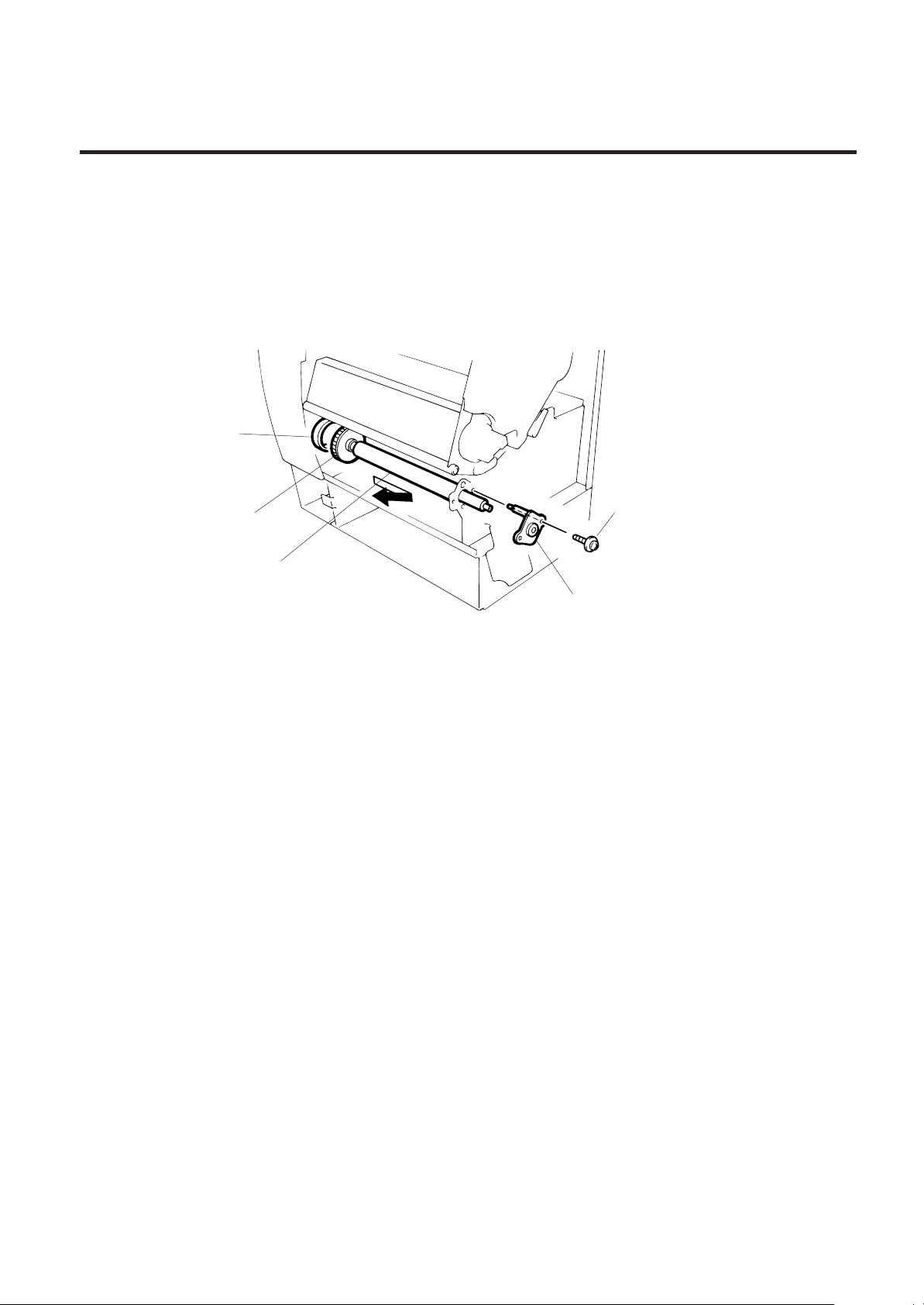
2.7 REPLACING THE PLATEN
1) Remove the front plate. (Refer to Fig. 2-6.)
2) Loosen the two screws (SM-4 x 10C) securing the stepping motor.
3) Remove the (FL-4 x 6) screw to detach the platen positioning plate.
4) Take the platen belt off the platen pulley, move the platen fully to the right and remove the platen from
the left end.
Platen Belt
Platen Pulley
Platen
Platen Positioning Plate
Screw (FL-4 x 6)
Fig. 2-14
5) Replace and install the platen, then place the platen belt around the platen pulley.
6) Install the platen positioning plate.
7) Press down on the stepping motor with 3.5 Kg ± 300 g force and secure it so the platen belt and the
feed roller belt have no slack, are engaged and evenly tense.
8) Reassemble the remaining parts in the reverse order of removal.
2-9
Page 13
2. MAJOR UNIT REPLACEMENT
2.8 REPLACING THE ROLLER BELT AND FEED ROLLER
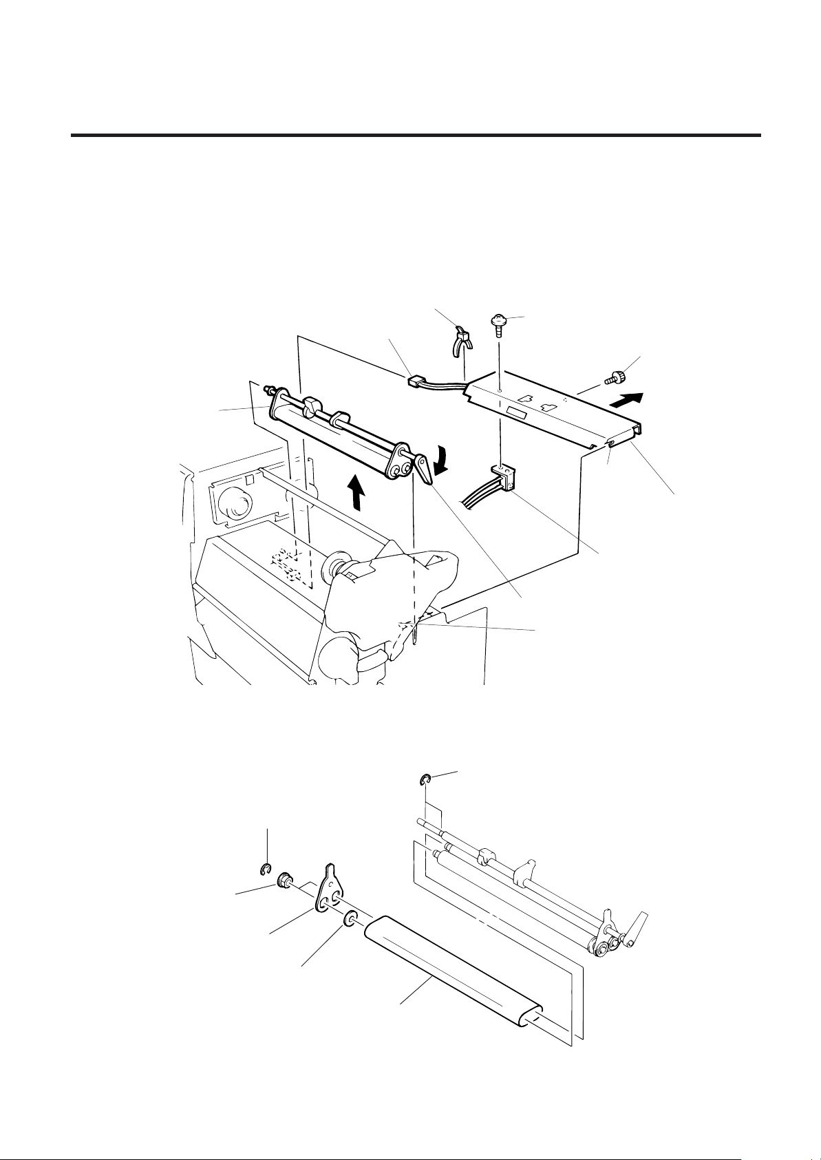
2.8 REPLACING THE ROLLER BELT AND FEED ROLLER
1) Lower the pinch roller lever.
2) Remove the white screw to detach the ribbon end sensor plate.
3) Remove the FL-3 x 5 screw, cut the cable band and remove the head-up switch.
4) Detach the connector of the ribbon end sensor.
EM18-33013
5) Removal the pinch roller block.
Pinch Roller Block
Cable Band
FL-3 x 5
Connector
White Screw
Notch
Ribbon End
Sensor Plate
Head-Up Switch
Pinch Roller Lever
Stud
Fig. 2-15
NOTE: Fit both sides of the studs into the notches when installing the ribbon end sensor plate.
6) Remove the four E-rings (E-5), pinch roller holder, bush, pinch roller washer, and then roller belt.
E-ring (E-5)
E-ring (E-5)
Bush
Pinch Roller Holder
Pinch Roller Washer
Roller Belt
2-10
Fig. 2-16
Page 14
2. MAJOR UNIT REPLACEMENT
2.8 REPLACING THE ROLLER BELT AND FEED ROLLER
EM18-33013
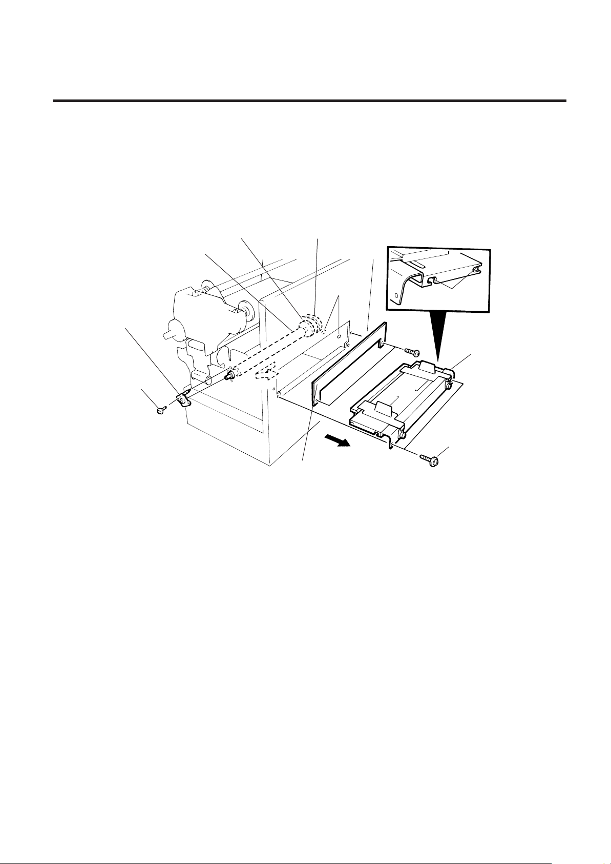
7) Remove the two (FL-4x6) screws and detach the media plate.
8) Remove the two (FL-4x6) screws and detach the media guide unit.
9) Loosen the two (SM-4x10C) screws securing the stepping motor.
10) Remove the two screws to detach the feed roller positioning plate.
11) Take the feed roller belt off the feed roller, move the feed roller fully to the left and remove the feed
roller form the right end.
Roller Pulley
Feed Roller Feed
Feed Roller Belt
Stud
Feed Roller
Positioning Plate
Screw (FL-4x6)
Media Plate
Notch
Media Guide Unit
Screw (FL-4x6)
Fig. 2-17
NOTE: Fit both sides of the studs into the notches when installing the media guide unit.
12) Replace and install the feed roller, place the feed roller belt around the feed roller pulley.
13) Install the feed roller positioning plate.
14) Press down on the stepping motor with 3.5 Kg ± 300 g force and secure it so the platen belt and
the feed roller belt have no slack, are engaged and evenly tense.
15) Reassemble the remaining parts in the reverse order of removal.
2-11
Page 15
2. MAJOR UNIT REPLACEMENT
2.9 REPLACING THE MEDIA SENSOR
EM18-33013
2.9 REPLACING THE MEDIA SENSOR
CAUTION:
1. When using the fixed sensor, line up the feed gap sensors between the upper and lower sensors.
2.
When shipped from the factory, the black mark sensor is positioned at the center of the effective
print area and the feed gap sensor is located 10 mm left of center as viewed from the front.
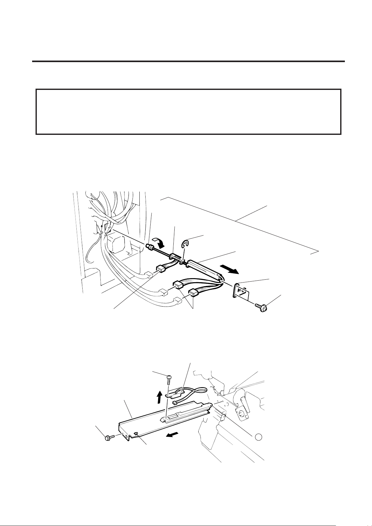
1) Detach the 4 connectors from the fixed/movable media sensors.
2) Remove the two screws (FL-3 x 4) and the sensor holder to detach the media sensor unit.
3) Turn the knob of the sensor shaft clockwise and remove the movable media sensor.
4) Remove the E-ring (E-3) from the sensor shaft and detach the lower fixed media sensor.
Media Sensor Unit
Knob
Fixed Media Sensor
E-ring (E-3)
Movable Media Sensor
Media Guide Plate
Screw (FL-3x4)
Connecter
Connecter
Fig. 2-18
5) Remove the white screw to detach the media guide plate.
6) Remove the two SM-3 x 6B screws, then unclamp and detach the upper fixed media sensor.
Upper Fixed Media Sensor
Screw (SM-3 x 6B)
Media Guide Plate
White Screw
B
Clamp
Fig. 2-19
7) Replace the fixed/movable media sensors and reassemble in the reverse order of removal.
2-12
Page 16

2. MAJOR UNIT REPLACEMENT
2.10 PERIODIC PARTS REPLACEMENT
(Revision Date Sep. 29 ’95)
EM18-33013
2.10 PERIODICAL PART REPLACEMENT
.oNemaNtraP.oNtraP
1rotoMnobbiR
2dioneloS
3netalP1054400CBMFmK05
4relloRdeeF1064400CBMFmK05
1050300BBMF
2050300BBMF
2012300BBMF
3012300BBMF
mK037
folavretnIdradnatS
tnemecalpeR
semit000,000,1
Since the above intervals are the standard values for a fully maintained machine, they are not
guaranteed, The values vary depending on the operating environment (dust or debris) or use of proper
media and ribbon.
2-13
Page 17
3. INSTALLATION PROCEDURE FOR OPTIONAL EQUIPMENT
3.1 HIGH SPEED PC INTERFACE BOARD (B-4800-PC-QM)
3. INSTALLATION PROCEDURE FOR OPTIONAL
EQUIPMENT
WARNING!
Make sure to unplug the power cord before installing any optional equipment.
3.1 HIGH SPEED PC INTERFACE BOARD (B-4800-PC-QM)
EM18-33013
Description
BPE PC board
BPC PC board
Printer cable
Cable support plate
The high speed PC interface board can be used together with the IBM PC-AT or compatible machine
only.
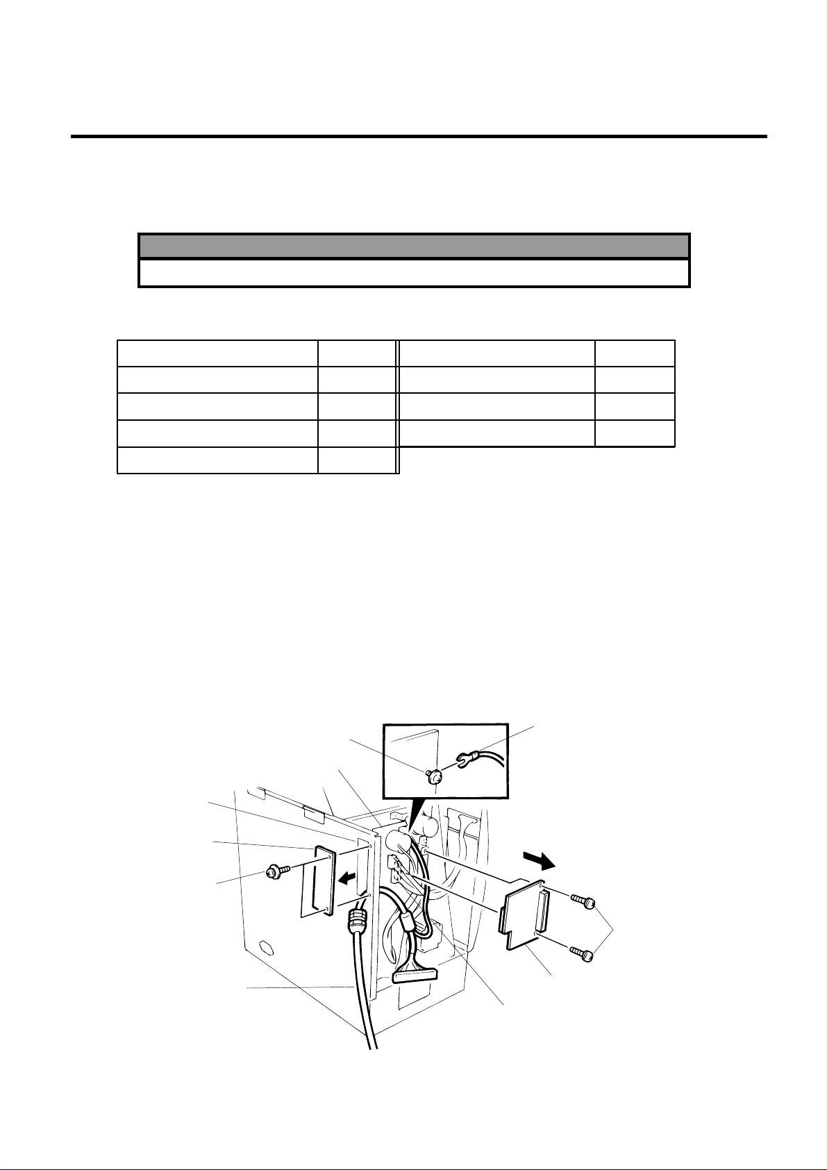
1) Open the top cover and right side cover. (See Fig. 2-1.)
2) Remove the left side cover. (See Fig. 2-1.)
3) Remove the two FL-3 x 5 screws to detach the blind plate.
4) Pass the printer cable through the opening.
5) Fasten the ground wire of the printer cable to the CPU PC board at the upper right with the
SM-3 x 6B screw which secures the CPU PC board.
6) Remove the two SM-4 x 8C screws from the BPE attachment plate.
7) Install the BPE PC board on the CN5 of the CPU PC board with the screws removed in step 6.
Screw (SM-3 x 5B)
Q'ty/Unit
1
1
1
1
Description
Locking support
Program diskette
Owner's Manual
Ground Wire
Q'ty/Unit
2
1
1
Opening
Blind Plate
Screw (FL-3 x 5)
Printer Cable
CPU PC Board
Screw (SM-4 x 8C)
BPE PC Board
Connector (CN5)
Fig. 3-1
3-1
Page 18
3. INSTALLATION PROCEDURE FOR OPTIONAL EQUIPMENT
3.1 HIGH SPEED PC INTERFACE BOARD (B-4800-PC-QM)
EM18-33013
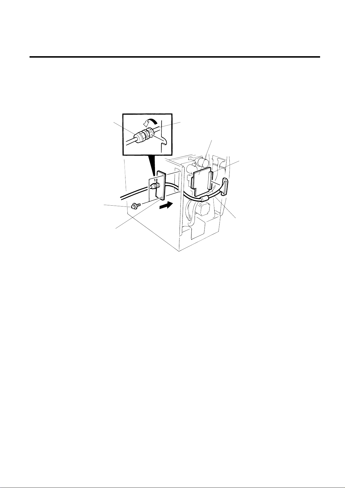
8) Connect the printer cable to connecter (CN1) on the BPE PC board.
9) Place the cable strain relief of the printer cable in the notch of the cable support plate. Secure the
cable strain relief to the cable support plate by turning the nut.
10) Attach the cable support plate to the printer with the FL-3 x 5 screws removed in the step 3.
Cable Strain Relief
Screw (FL-3 x 5)
Cable Support Plate
Nut
BPE PC Board
Connector (CN1)
Printer Cable
11) Reassemble in the reverse order of removal.
12) The following procedure should be employed with your PC.
13) Set the DIP SW. on the BPC PC board for the I/O address according to your PC.
Fig. 3-2
14) Install the BPC PC board in the expansion port bus line of your PC.
15) Connect the printer cable mentioned in step 5 to the BPC PC board.
16) Insert the attached FDK into the FDD and install the data in the hard disk. Since the installation
procedure is different between MS-DOS and Windows, refer to the respective owner’s manual.
17) Perform a motion check.
3-2
Page 19
3. INSTALLATION PROCEDURE FOR OPTIONAL EQUIPMENT
3.2 CUTTER MODULE (B-4208-QM)
SVO7A1003: Nov. 21 ’97
EM18-33013
3.2 CUTTER MODULE (B-4208-QM)
NOTE: This module cannot be used together with the B-4908-H-QM strip module. Remove the strip
module if it has been attached to the printer.
Description Q’ty/Unit Description Q’ty/Unit
Cutter Unit 1 Cutter Attaching Screw 2
Cutter 1 Screw (FL-4x6) 2
Cutter Harnes 1 Screw (SM-4x6C) 1
Cutter Support 1 Cleaner 1
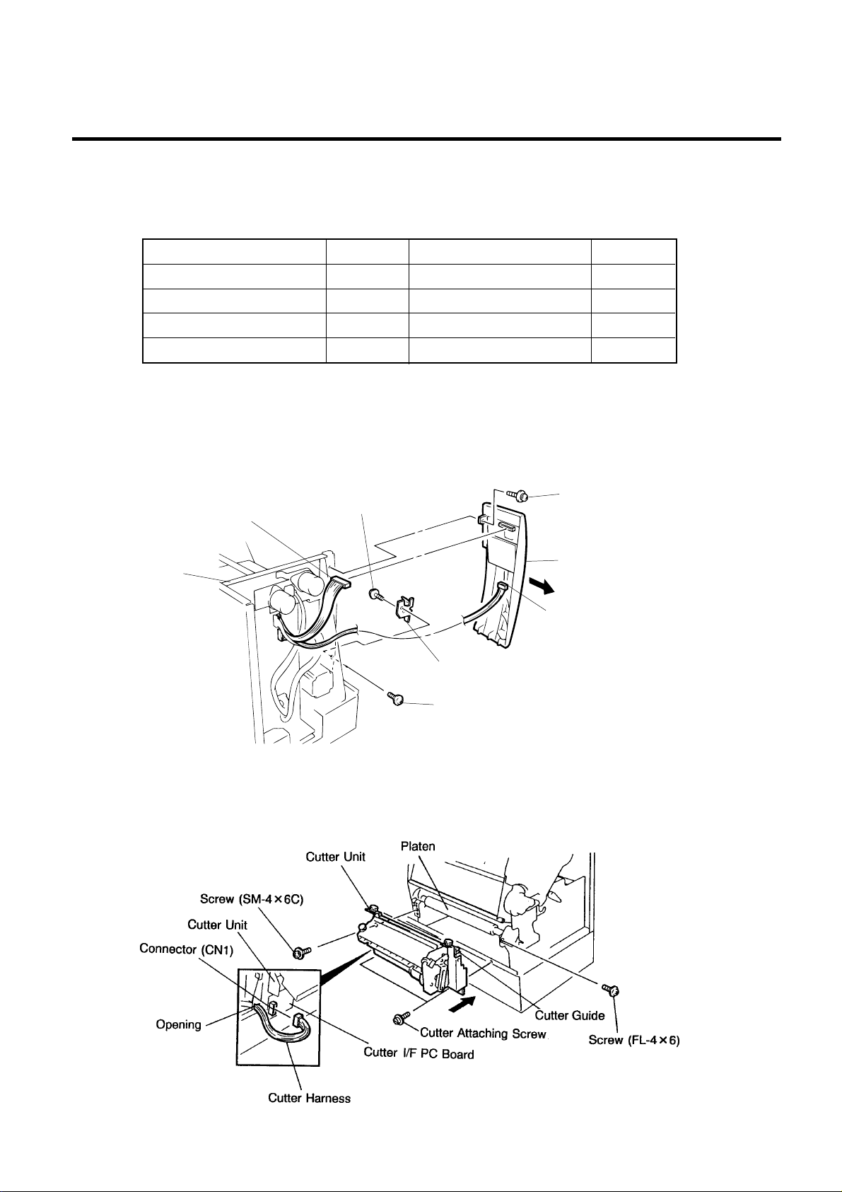
1) Open the right side cover and the top cover. (See Fig. 2-1.)
2) Remove the left side cover. (See Fig. 2-1.)
3) Remove the front plate. (See Fig. 2-6.)
4) Remove the screw (SM-4x8B) and two connectors to detach the operation panel.
5) Attach the cutter support to the main frame with the two screws (FL-4x6).
Screw (FL-4x6)
Connector
Screw (SM-4x8B)
Main Frame
Cutter Support
Screw (FL-4x6)
Operation Panel
Connector
Fig. 3-3
6) Install the cutter unit with the attached four screws (cutter attaching screw, SM-4x6C and
FL-4x6).
7) Connect the cutter harness to CN1 on the cutter I/F PC board through the opening of the cutter unit.
When installing the cutter, make sure that the cutter guide is not in contact with the platen. If it is, print
failure or noise may be caused.
3-3
Fig. 3-4
Page 20
3. INSTALLATION PROCEDURE FOR OPTIONAL EQUIPMENT
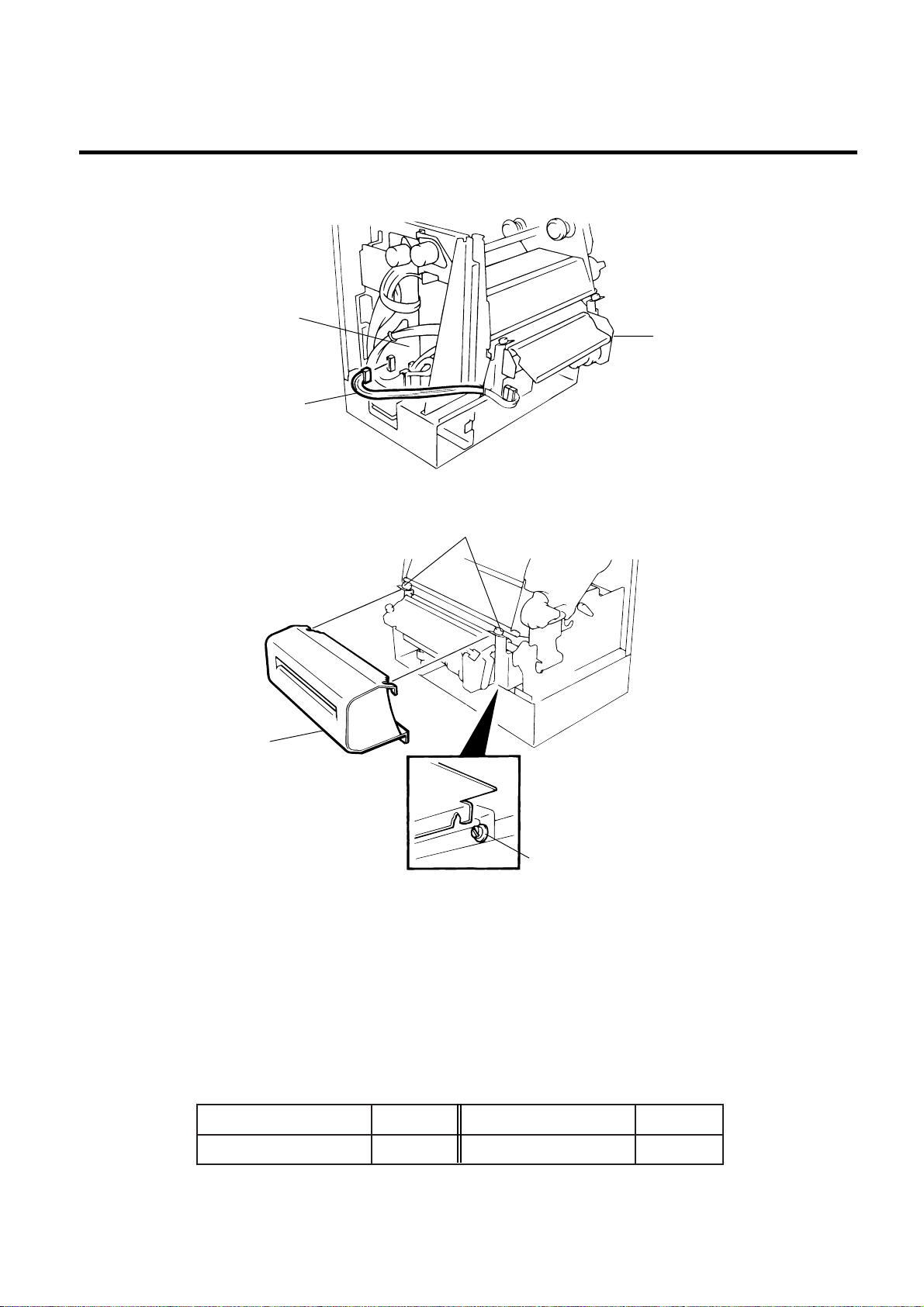
8) Connect the cutter cable to the CN15 on the CPU PC board.
CPU PC Board
(Revision Date Sep. 27 ’95)
EM18-33013
3.2 CUTTER MODULE (B-4208-QM)
Cutter Unit
Cutter Harness
9) Mount the cutter cover with the two screws.
Cutter Cover
Fig. 3-5
Screw
Cutter Attaching Screw
Fig. 3-6
10) Mount the operation panel and the left side cover on the printer.
11) Close the top and right covers.
12) After reassembly is complete, perform a test print to confirm that the cutter works properly. If the print
start position becomes misalign when media is fed in the reverse direction, fine adjust the back feed
value using the Back Feed Fine Adjustment procedure in diag. mode.
NOTES: 1. If the top edge of label winds onto the platen in cut issue, set DIP SW. 1-5 to ON.
(Refer to the Owner’s Manual.)
2. Retain the parts that are removed during installation of the cutter unit. They will be
required when the printer is modified to a standard type.
straPdevomeRtinU/yt'QstraPdevomeRtinU/yt'Q
etalptnorF1 )6x4-LF(wercS3
3-4
Page 21
3. INSTALLATION PROCEDURE FOR OPTIONAL EQUIPMENT
(Revision Date Apr. 7 '98)
3.3 MEMORY MODULE
EM18-33013
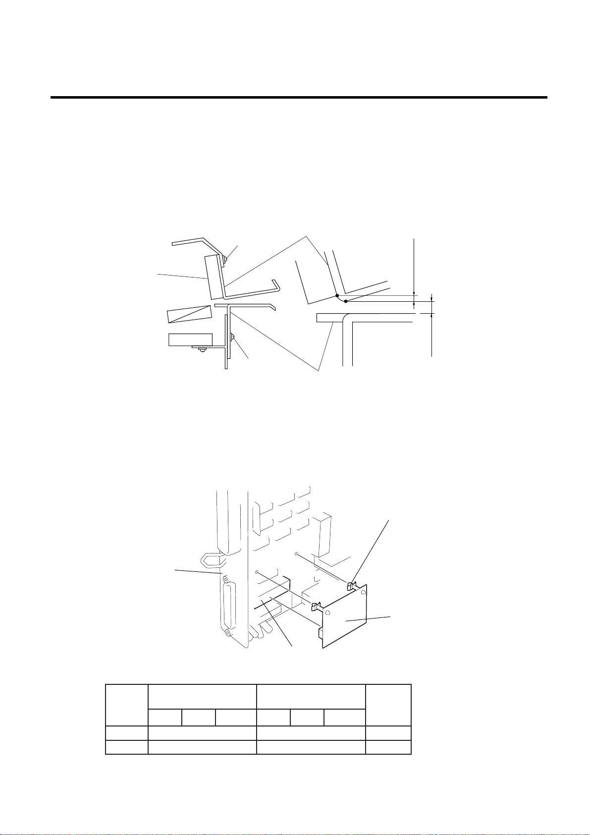
■ Adjusting the Cutter Guide Plates
After replacing the cutter unit the following adjustment procedure should be employed to prevent
paper jams.
1. Attach the cutter guide plate A with two SM-4 x 6C screw so that the fixed cutter is positioned 0.1
mm to 0.4 mm above the bottom of the cutter guide plate A.
2. Attach the cutter guide plate B with two FL-4 x 8 screws so that there is a clearance of 0.5 mm
between the cutter guide plate A and cutter guide plate B using a clearance gauge.
Screw
(SM-4 x 6)
Fixed Cutter
Cutter Guide Plate B
0.1 ~ 0.4 mm
0.5 mm
Fig. 3-7
Screw
(FL-4 x 8)
Cutter Guide Plate A
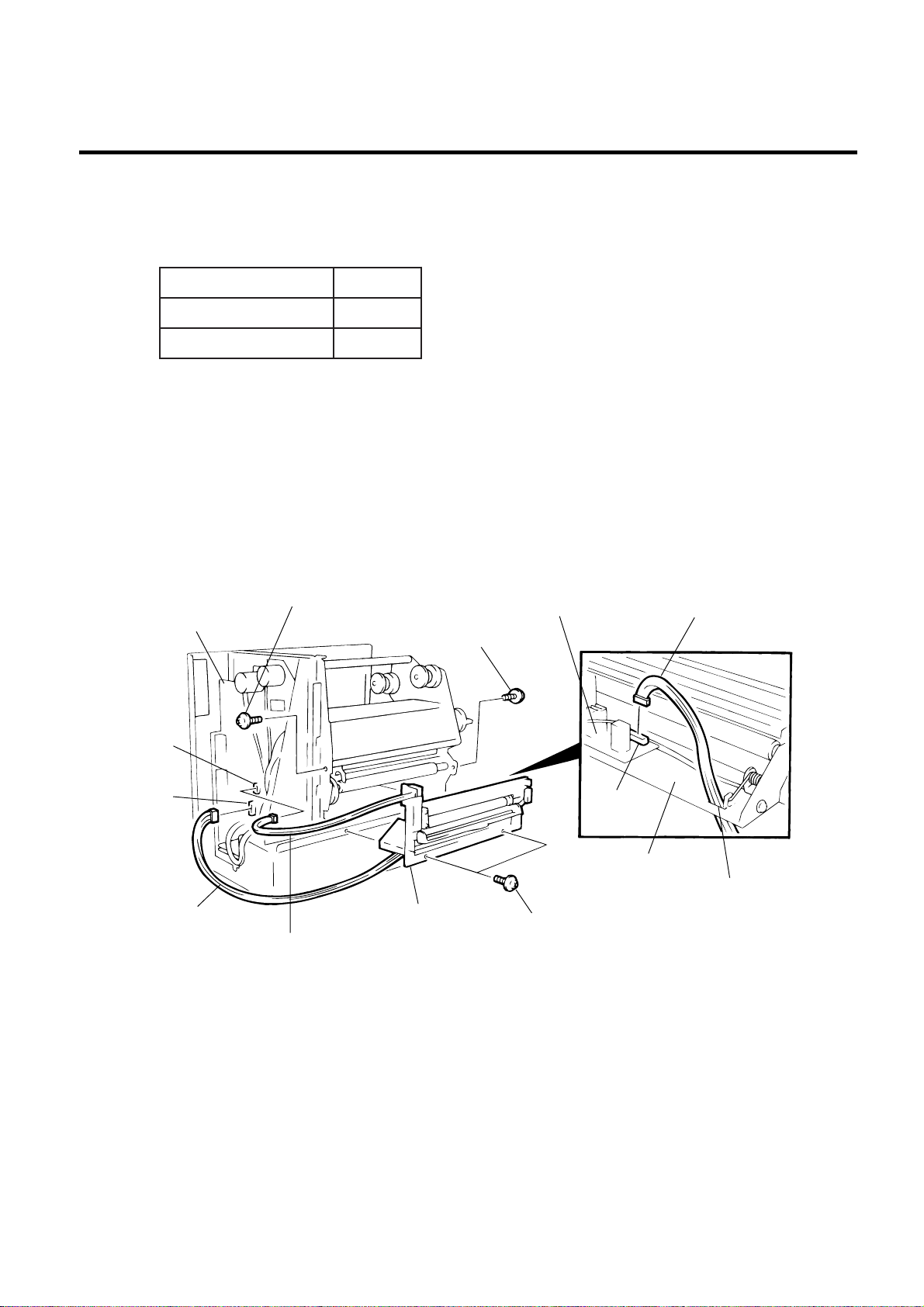
3.3 MEMORY MODULE
1) Open the right side cover and the top cover. (See Fig. 2-1.)
2) Remove the left side cover. (See Fig. 2-1.)
3) Remove the CPU PC board. (See Fig. 2-2.)
4) Directly connect the D-RAM PC board to CN20 on the CPU PC board, and then secure it with the
two locking support.
Locking Suppoert
CPU PC Board
D-RAM PC
Board Ass’y
IC20
MAR
yticapaC
BM20.023x3.3120.061x3.312dradnatS
BM43.166x3.3126.033x3.312noitpO
hctaBpirtStuc-otuAhctaBpirtStuc-otuA
ezisgniward.xaM
)mm()H(x)W()lamron(
eziagniward.xaM
)mm()H(x)W()ylf-eht-no(
3-5
Fig. 3-8
skrameR
Page 22
3. INSTALLATION PROCEDURE FOR OPTIONAL EQUIPMENT
3.4 STRIP MODULE (B-4908-H-QM)
(Revision Date Aug. 18 ’95)
EM18-33013
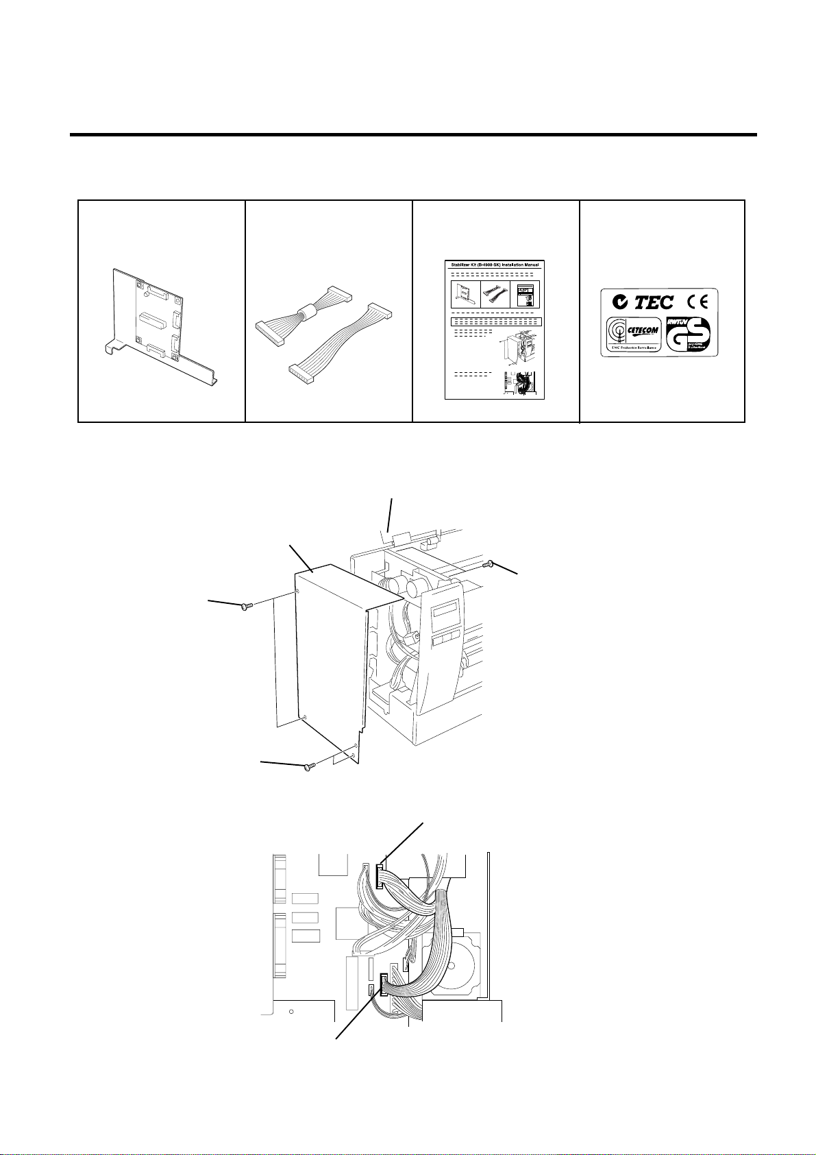
3.4 STRIP MODULE (B-4908-H-QM)
NOTE: This module cannot be used together with the B-4208-QM cutter module. Remove the cutter
module if it has been attached to the printer.
noitpircseDtinU/yt'Q
tinUpirtS1
ssenraHpirtS1
1) Open the right side cover and the top cover. (See Fig. 2-1)
2) Remove the left side cover (See Fig. 2-1)
3) Remove the front plate (See Fig. 2-6)
4) Remove the operation panel (See Fig. 3-3)
5) Connect the strip harness to the CN2 on the PWM PC board through the opening of the strip base.
6) Install the strip unit to the printer with the four FL-4 x 6 screws removed in STEP 3.
7) Connect the strip harness to the CN15 on the CPU PC board.
8) Connect the strip sensor harness to the CN12 on the CPU PC board.
CPU PC Board
CN12
CN15
Strip Harness
Screw (FL-4 x 6)
Screw (FL-4 x 6)
Strip Unit
Strip Sensor Harness
PWM PC Board
CN2
Strip Base
Screw (FL-4 x 6)
9) Mount the operation panel and the left side cover on the printer.
Strip Harness
Opening
Fig. 3-9
10) Close the top and right covers.
11) Refer to Section 6.4 of the Maintenance Manual to load the label and make a test print to check
forproper strip issue. If not, refer to Section 6.3.2 of the Maintenance Manual to adjust the strip
position.
3-6
Page 23
3. INSTALLATION PROCEDURE FOR OPTIONAL EQUIPMENT
3.5 STABILIZER KIT
(Revision Date: Jul. 26 ’99)
EM18-33013
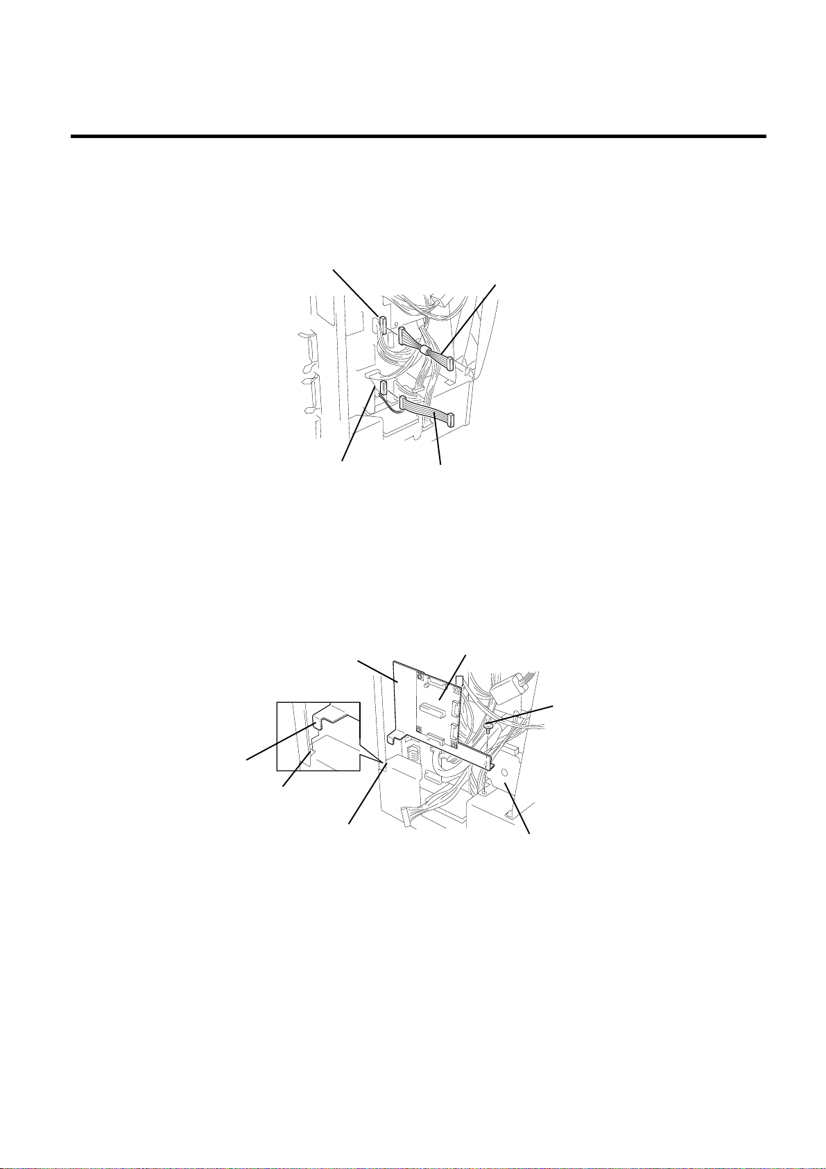
3.5 STABILIZER KIT
Stabilizer PC Board Ass’y
(1 pc.)
Harness S (1 pc.) ... Yellow
Harness P (1 pc.) ... Black
Installation Manual (1 pc.)
EU Standard Sticker (1 pc.)
1) Turn the power of the printer off, then open the top cover. Remove the six screws to detach the left side
cover.
Top Cover
Left Side Cover
Screw
Screw
Screw
Fig. 3-10
2) Detach the yellow and the red cables from the CN 9 and the CN 17 on the CPU PC board.
CN9
CN17
3-7
Fig. 3-11
Page 24
3. INSTALLATION PROCEDURE FOR OPTIONAL EQUIPMENT
(Revision Date: Jul. 26 ’99)
EM18-33013
3.5 STABILIZER KIT
3) Connect the harness S (yellow) to the CN 9 on the CPU PC board and the harness P (black) to the
CN 17, respectively.
NOTE: As for the harness, connect the connector housing which has fewer pins to the connector on
the CPU PC board side.
CN9
CN17
Harness P (Black)
Harness S (Yellow)
Fig. 3-12
4) Remove the screw A, then insert the guide plate provided to the stabilizer PC board ass’y into the
square hole of the part B. Secure the stabilizer PC board ass’y using the screw A.
Guide Plate
Stabilizer PC Board Ass’y
Guide Plate
Square Hole
Part B
Screw A
Stepping Motor
Fig. 3-13
3-8
Page 25
3. INSTALLATION PROCEDURE FOR OPTIONAL EQUIPMENT
(Revision Date: Jul. 26 ’99)
EM18-33013
3.5 STABILIZER KIT
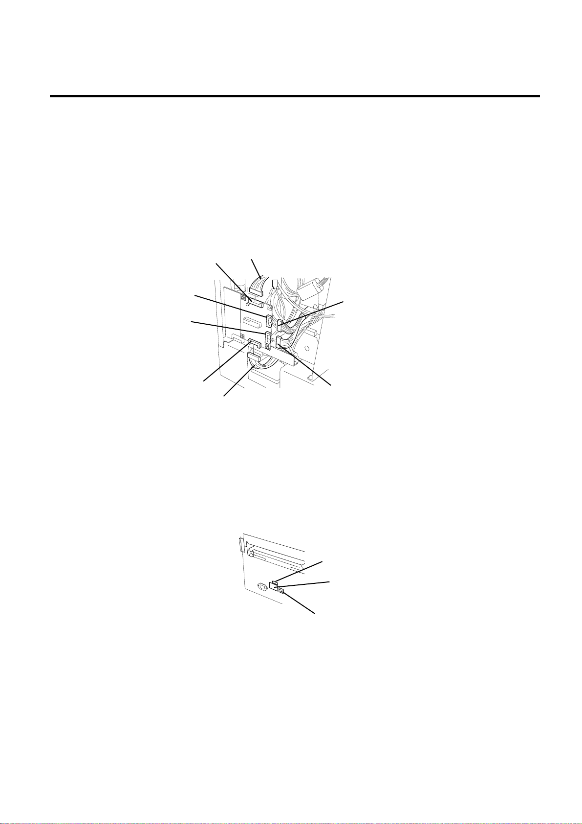
5) Connect the harness S (yellow) to the CN 2 on the stabilizer PC board ass’y and the harness P (black)
to the CN 3, respectively. Respectively connect the red and the yellow cables detached in the step
2 to the CN 4 and the CN 5 on the stabilizer PC board ass’y.
CN 2:Harness S(Yellow) CN 4:Red cable
CN 3:Harness P (Black) CN 5:Yellow cable
NOTES: 1. The connector design prevents wrong insertion. Therefore, when you connect the
connectors, care must be taken to the connector faces and avoid forcibly pressing the
connectors.
2.After you connect the connectors, check that no looseness exists on them.
CN2
CN5
CN4
CN3
Harness P (Black)
Harness S (Yellow)
Yellow Cable
Red Cable
Fig. 3-14
6) Secure the left side cover using the six screws, then close the top cover. Stick the attached EU
standard sticker on the sticker currently stuck.
NOTE:
Care must be taken to the cables when attaching the left side cover.
3-9
ROM Version Sticker
Model Name Sticker
EU Stundard Sticker
Fig. 3-15
Page 26
4. MECHANISM DESCRIPTION
4.1CUTTER DRIVE (CUTTER MODE)
EM18-33013
4. MECHANISM DESCRIPTION
4.1 CUTTER DRIVE (CUTTER MODE)
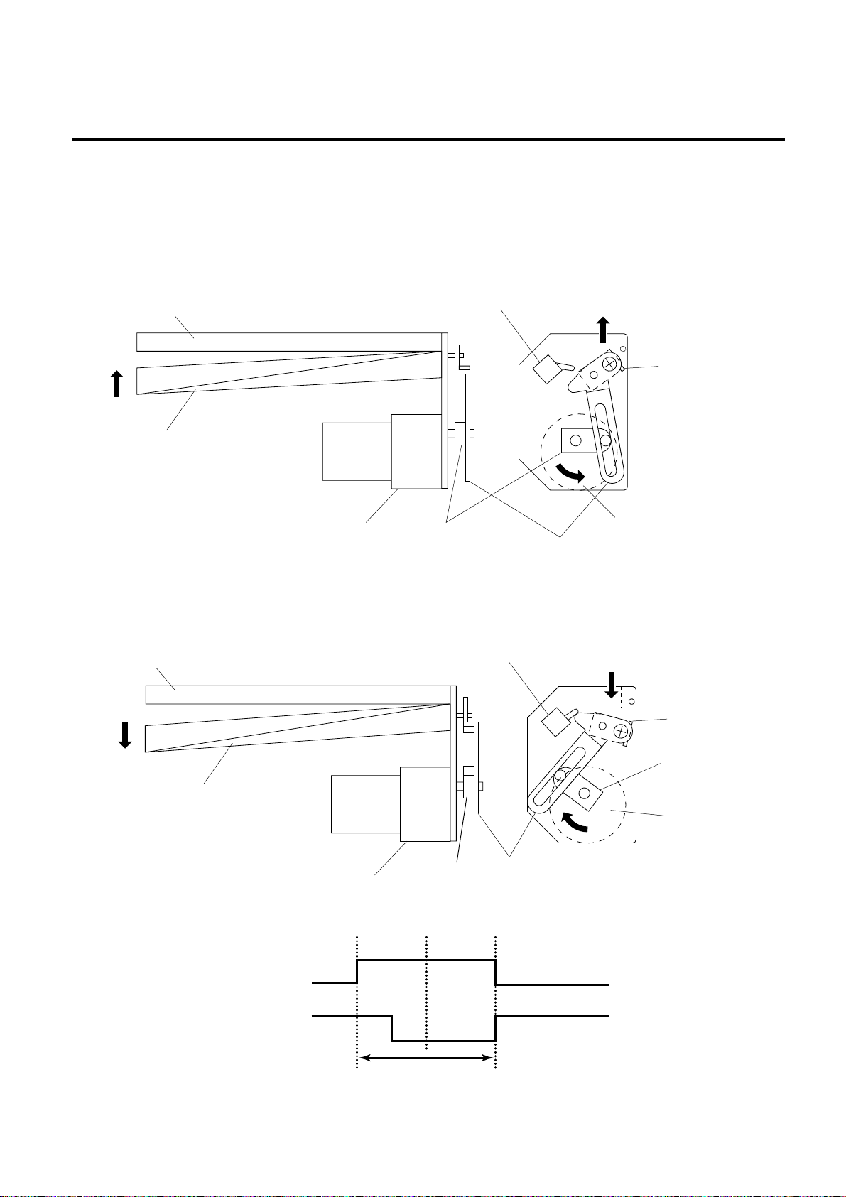
The printer supplies DC + 27 V to the cutter motor to rotate it and the clutch counter clockwise. The arm
swings like a pendulum and moves the fixed slide cutter up and down to make a cut.
Fixed Cutter
Micro Switch
Slide Cutter
Slide Cutter
Cutter Motor
Clutch
Arm
Cutter Motor
Fig. 4-1
After making a cut, the arm turns the micro switch off and the cutter home position is detected.
When the cutter does not return to the home position because of a paper jam, an error occurs and the
next piece of paper will not be cut.
Fixed Cutter
Micro Switch
Slide Cutter
Timing chart
+27
MOTOR
CHOME
Micro Switch
Cutter Motor
Open
Clutch
Close Open
Cutting
(one cycle)
4-1
Slide Cutter
Clutch
Cutter Motor
Arm
Fig. 4-2
Page 27

5. TROUBLESHOOTING
5. TROUBLESHOOTING
Problems Cause Solution
(Revision Date Sep. 29 ‘95)
EM18-33013
5. TROUBLE SHOOTING
Power does not turn
ON.
LED or LCD does not
light.
1. Input voltage to the printer is not
within the rated voltage.
(Check by CN1 on the PS unit.)
2.Output voltage from the printer is not
within the rated voltage.
(Check that the voltage between Pin
4 and Pin 6 (GND) of CN1 on the PS
unit is 27 V.
And check that the voltage between
Pin 11 and Pin 6 ( GND) is 5 V.)
3.No voltage to the CPU PC board.
(Check that the voltage between Pin
1 and Pin 5 (GND) of CN16 on the
CPU PC board is 27 V.
And check that the voltage between
Pin 11 and Pin 5 (GND) is 5 V.)
4.Failure of CPU PC board.
1.Failure of the LED board/LCD
2.Failure of the LCD/LED harness
3.Failure of the CPU PC board
• Replace the power cable orpower
inlet.
• Replace the PS unit.
• Replace the power harness.
• Replace the CPU PC board.
• Replace the LED board/LCD.
• Replace the LCD/LED harness.
• Replace the CPU PC board.
Poor printing
Printer does not print
Dot missing
1.The print paper is of poor quality.
2.Dirty print head
3.The head lever fastens the print head
incompletely.
1.Print head failure
2.Connection of the print head
connector is incomplete,a bad
contact, or broken wires.
3. Failure in rewinding/feeding of the
ribbon.
4.Failure of the CPU PC board
5.Failure of the software
6.Failure of the printer cable
1.Broken print head element
2.Broken print head cable wires
3.Failure of the CPU PC board
• Use the media approved by
TOSHIBA TEC.
• Clean the print head.
• Fasten the head lever completely.
• Replace the print head.
• Connect the harness completely,
or replace the harness.
• Replace the ribbon rewind motor,
ribbon feed motor or CPU board.
• Replace the CPU PC board.
• Check the program.
• Replace the printer cable.
• Replace the print head.
• Replace the print head harness.
• Replace the CPU PC board.
•
•
•
5-1
Page 28

5. TROUBLESHOOTING
Problems Cause Solution
(Revision Date Sep. 29 ‘95)
EM18-33013
5. TROUBLE SHOOTING
Blurred print
Ribbon wrinkle
Ribbon end error
Label feed failure
1.Poor media quality.
2.Dust is on the media.
1.Poor ribbon quality
2.Ribbon is not rewound or fed
smoothly.
1.Poor ribbon quality
2. Improper voltage applied to the ribbon
end sensor
3.Failure of the ribbon end sensor
4.Failure of the circuit which controls
the ribbon end sensor.
1.Paper is not set properly.
2.Paper of poor quality
3.Improper adjustment of the feed gap
sensor or black mark sensor.
4.The proper media sensor is not
selected.
5.Threshold is improper.
6. Failure of the feed gap sensor or
black mark sensor
7. Labels cannot be stripped off the
backing paper or the backing paper
with labels cannot be wound properly.
8.The cutter mechanism is not installed
properly.
9.Failure of the stepping motor
• Use only TOSHIBA TEC specified
media.
• Clean the print head and remove
any dust from the media.
• Use only TOSHIBA TEC specified
ribbon.
• Replace the ribbon rewind mo tor
or ribbon feed motor.
• Use only TOSHIBA TEC specified
ribbon.
• Refer to page 2-3 to adjust the
ribbon end sensor.
• Replace the ribbon end sensor.
• Replace the CPU PC board.
• Set the paper properly.
• Use paper approved by TOSHIBA
TEC.
• Re-adjust the sensor.
• Select the media sensor by DIP
switch and adjust the sensitivity of
the sensor.
(Refer to page 6-40, 41)
• Set the threshold.
(Refer to Owner’s Manual.)
• Replace the feed gap sensor or
black mark sensor.
• Replace the take-up motor or CPU
PC board.
• Install the cutter mechanism
properly.
• Replace the stepping motor or
CPU PC board.
Communication error
1.Failure of the communication cable
2.Failure of the RS-232C connecter
3.Failure of the communication
connector
4.Failure of the PC or application
software
5.Failure of the CPU PC board
5-2
• Replace the cable.
• Replace the connector.
• Replace the connector.
• Modify the program.
• Replace IC51 (MC145407).
If the trouble is not solved, replace
the CPU PC board.
Page 29

(Revision Date: Dec. 10 '99)
EM18-33013
TABLE OF CONTENTS
Page
6. DIAG. TEST OPERATION.................................................................................. 6- 1
6.1 OUTLINE OF THE DIAG. TEST OPERATION ........................................... 6- 1
6.2 SELF TEST MODE ..................................................................................... 6- 3
6.2.1 Maintenance Counter Printing............................................................ 6- 3
6.2.2 Automatic Diagnostic Printing ............................................................ 6- 6
6.2.3 Head Broken Element Check............................................................ 6-12
6.3 PARAMETER SETTING MODE ................................................................ 6-13
6.3.1 Feed Length Fine Adjustment ........................................................... 6-15
6.3.2 Cut/Strip Postion Fine Adjustment .................................................... 6-16
6.3.3 Back Feed Length Fine Adujustment ................................................ 6-17
6.3.4 X Axis Fine Adjustment ..................................................................... 6-22
6.3.5 Print Tone Fine Adjustment............................................................... 6-24
6.3.6 Character Code Selection ................................................................. 6-25
6.3.7 Font Zero Selection........................................................................... 6-26
6.3.8 Control Code Selection ..................................................................... 6-27
6.3.9 Ribbon Type Selection.................................................................... 6-29
6.3.10 Ribbon Motor Drive Voltage Fine Adjustment ................................. 6-30
6.3.11 Strip Wait Status Setting ................................................................. 6-31
6.3.12 Threshold Manual Fine Adjustment for the Black Mark Sensor ...... 6-32
6.3.13 Threshold Manual Fine Adjustment for the Feed Gap Sensor........ 6-33
6.3.14 Kanji Code Selection....................................................................... 6-36
6.3.15 Euro Font Code Selection ............................................................... 6-37
6.3.16 Head Type Selection ....................................................................... 6-38
6.3.17 Transmission Control Mode Selection ............................................ 6-39
6.3.18 Reset selection when the INPUT • PRIME Signal is ON ................ 6-40
6.4 TEST PRINT MODE .................................................................................. 6-41
6.4.1 Normal Test Print ............................................................................ 6-41
6.4.2 Process Test Print........................................................................... 6-47
6.5 SENSOR SETTING MODE........................................................................ 6-49
6.5.1 Thermistor Check............................................................................ 6-49
6.5.2 Black Mark Sensor Adjustment....................................................... 6-50
6.5.3 Feed Gap Sensor Adjustment......................................................... 6-52
6.5.4 Paper End Setting for Black Mark Sensor....................................... 6-52
6.5.5 Paper End Setting for Feed Gap Sensor ........................................ 6-53
6.6 RAM CLEAR MODE .................................................................................. 6-54
6.6.1 Maintenance Counter Clear ............................................................ 6-56
6.6.2 Parameter Clear.............................................................................. 6-57
CAUTION:
1. This manual may not be copied in whole or in part without prior written permission of
TOSHIBA TEC.
2. The contents of this manual may be changed without notification.
3. Please refer to your local Authorized Service representative with regard to any queries
you may have in this manual.
Page 30

6. DIAG. TEST OPERATION
6.1 OUTLINE OF THE DIAG. TEST OPERATION
(Revision Date: Jan. 14 ‘99)
EM18-33013
6. DIAG. TEST OPERATION
6.1 OUTLINE OF THE DIAG. TEST OPERATION
In system mode the diag. test operation is used to diagnose the printer and to set to the parameters by
using the [FEED], [RESTART] and [PAUSE] keys on the operation panel. Diag. test operation
(Type 1) is started from the power off state and the parameter setting (Type 2) is started while the printer
is on-line or printing. For further details, please refer to the corresponding pages.
NOTE: Every size in this manual is written in millimeter. To obtain the size in inch, divide by 25.4.
■ Type 1
Power off
Turn on the power while
holding down the [FEED]
key and [PAUSE] key.
Press the [RESTART] key.
<1 DIAGNOSTIC V1.OA>
Press the [RESTART] key. Press the [FEED] key.
<2 PARAMETER SET>
Press the [RESTART] key. Press the [FEED] key.
<3 TEST PRI NT>
Press the [RESTART] key. Press the [FEED] key.
<4 SENSOR ADJUSTMENT>
Press the [RESTART] key. Press the [FEED] key.
■ Self Test Mode (See page 6-3)
Data from the maintenance counter and
automatic diagnosis are printed on the
media. The result of the head broken element
check is indicated in the display.
■ Parameter Setting Mode (See page 6-13)
Fine adjustment of the feed length, cut/strip
position, back feed, X axis, print tone, and
thresholds of the black mark sensor and feed
gap sensor, and selection of character font,
font zero, control code, ribbon type, ribbon
motor torque, strip wait status, Euro font code,
head type, transmission control mode, reset
ON/OFF when the INPUT • PRIME signal is
ON and stacker are available in this mode.
■ Test Print Mode (See page 6-39)
Print condition and test print type (slant line,
characters and bar code) are selectable.
■ Sensor Setting Mode (See page 6-47)
A thermistor check and the setting of the black
mark and feed gap sensors are available in this
mode.
A transmission check is made to both a print
head thermistor and an environmental
temperature thermistor.
<5 RAM CLEAR>
■ RAM Clear Mode (See page 6-52)
Data from the maintenance counter is cleared
Press the [FEED] key.
and parameter setting is initialized in the RAM
clear mode.
In system mode the [FEED], [RESTART] and [PAUSE] keys function as described below.
■ Key Function Table
emaNyeKnoitcnuF
yek]DEEF[
yek]TRATSER[
yek]ESUAP[
.yekretne
6-1
.)-(noitceridevitagenehtnisretemarapehttsujda
enifotroedomretemarapehtdetcelesotdesU.seodyek]ESUAP[asaedommetsysehttratsotdesU
)+(noitceridevitisopehtnisretemarapehttsujdaenifotroedomretemarapehttcelesotdesU
nasadesU.edomretemarapehttcelesotdnaseodyek]DEEF[asaedommetsysehttratsotdesU
Page 31
6. DIAG. TEST OPERATION
Power on
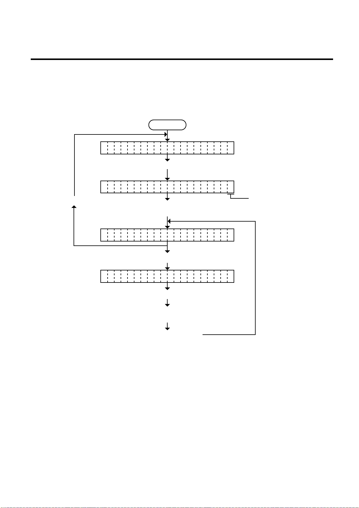
Press the [PAUSE] key. (See NOTE 1.)
ON LINE
Press the [PAUSE] key.
Press the [PAUSE] key.
<2 PARAMETER SET>
Press the [RESTART] key.
<1 RESET>
Hold down the [RESTART] key for
more than 3 seconds. (See NOTE 2.)
Refer to Section 6.3 Parameter Setting Mode
for the following procedure.
(See NOTE 3.)
Press the [PAUSE] key.
Indicates the number of
remaining media when the
[PAUSE] key is pressed.
PA SE 5U
6.1 OUTLINE OF THE DIAG. TEST OPERATION
EM18-33013
■ Type 2
The parameter setting such as feed length fine adjustment or cut/strip position fine adjustment can
be changed while the printer is on-line or printing. Pressing the [PAUSE] key cause the printer to enter
parameter setting mode. Rest mode is provided for this procedure to cancel the steps which follow
the [PAUSE] key without turning the power off.
NOTES: 1. Pressing the [PAUSE] key during printing causes the printer to pause printing and show
the number of remaining media.
2. If the [RESTART] key is released within 3 seconds, the printer will resume printing
because the [RESTART] key is activated.
3. Since the reset is performed when terminating this mode, the printer cancels the
remaining media and returns to on-line mode. This reset will not clear the changed
parameter settings.
6-2
Page 32
6. DIAG. TEST OPERATION
(Revision Date: Jan. 14 ‘99)
6.2 SELF TEST MODE
EM18-33013
6.2 SELF TEST MODE
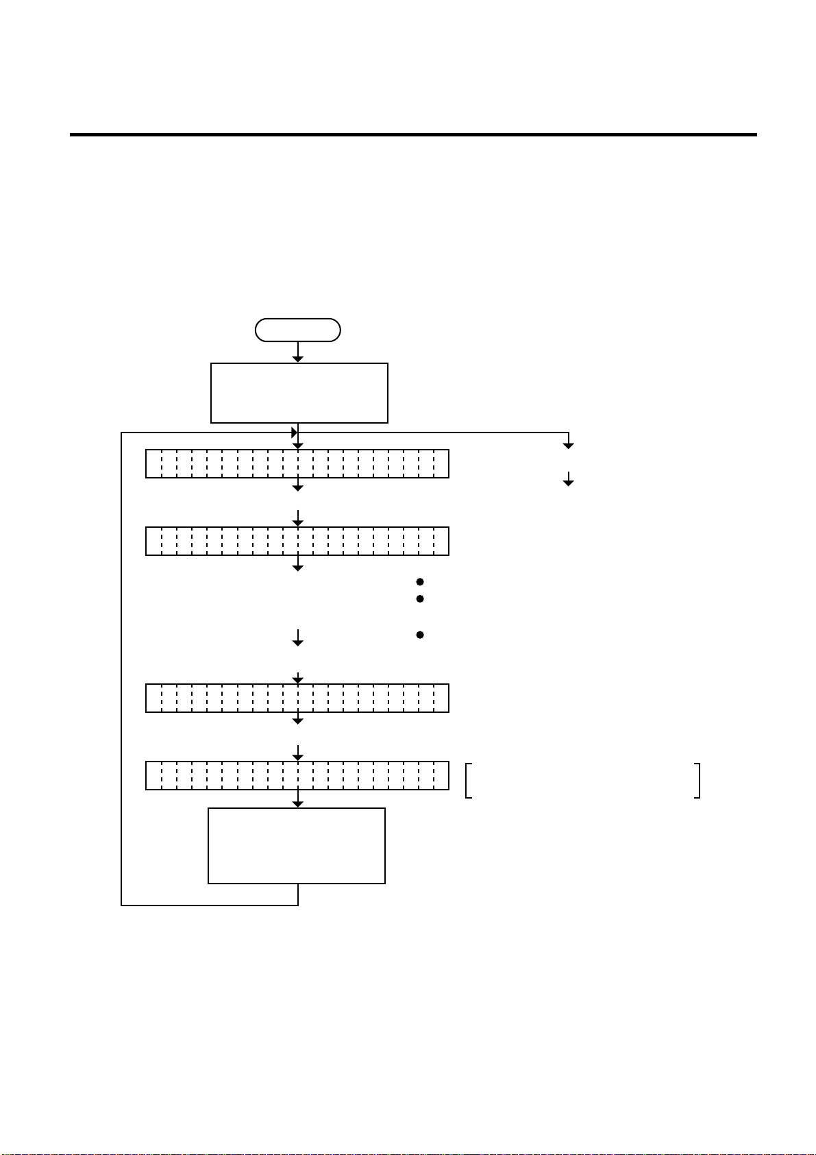
In self test mode the printer status is printed in two types of sample print. The result of the head broken
element check is indicated in the display.
6.2.1 Maintenance Counter Printing
The data from 1 to 31 on a sample print is printed. This data is the printer status and the value set
in the parameter setting mode.
Power off
Turn on the power while
holding down the [FEED]
key and [PAUSE] key.
<1 DIAGNOSTI C V1.OA>
Press the [PAUSE] key.
RI BON TRANSMISSIVEB
Select the ribbon type from those
at the right by pressing the
[FEED] key or [RESTART] key.
Press the [PAUSE] key.
MA NTENANCE COUNTERI
Press the [PAUSE] key.
CH CKING & PRINTINGE
The result of the self test
is printed. After printing,
the initial display will be
shown.
Press the [PAUSE] key.
Continued on Section 6.2.2
Automatic Diagnostics Printing.
NO RIBBON (No ribbon : Thermal direct)
TRANSMISSIVE
(Transmissive ribbon : Thermal transfer)
NO TRANS.
(Non-transmissive ribbon : Thermal transfer)
The printer is checking or printing
the status
NOTES: 1. If the maintenance counter printing results in an error, the printer will display the error
message and stop printing. The error status can be cleared by the [PAUSE] key,
however, the display will return to the initial display “<1> DIAGNOSTIC V1.0A”.
Printing is not automatically resumed after the error is cleared.
2. Both label and tag paper can be used for printing.
6-3
Page 33
6. DIAG. TEST OPERATION
(Revision Date: Dec. 10 ‘99)
EM18-33013
6.2 SELF TEST MODE
■ Sample Print
[Print Condition]
• Preset count :1
• Print speed : 101.6 mm/sec.
• Sensor : No sensor
• Printing method : Thermal transfer
• Supply length : 50 mm
• Issuing mode : Batch printing
(without rewinder)
(1)
TL FEED 1882.3km
(2)
FEED 20.5km
(3)
PRINT 15.0km
(4)
CUT 148150
(5)
HEAD U/D 170
(6)
RIBBON 32h
(7)
SOLENOID 0h
(8)
232C ERR 1
(9)
SYSERR 0
(10)
PW FAIL 0
(11)
FONT [PC-850] [0]
(12)
CODE [ESC LF NUL]
(13)
RIBN [TRANS.]
(25)
RIBN ADJ. [PC] + 0 +0 [KEY] + 0 +0
(26)
STATUS [OFF]
(27)
THRESHOLD R 1.0V
(28)
THRESHOLD T 0.7V
(29)
KANJI [TYPE1]
(30)
EURO CODE B0H
(31)
HEAD [TYPE1]
[PC]
FEED -10.0mm
CUT -5.0mm
BACK +3.0mm
TONE(T) +3step
TONE(D) +5step
[KEY]
FEED +5.0mm
CUT -1.5mm
BACK +0.5mm
TONE(T) +0step
TONE(D) +1step
X ADJ. +35.0mm
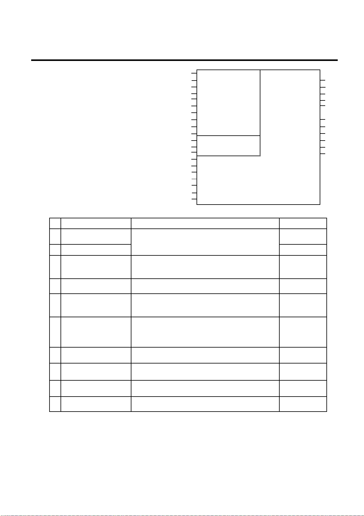
1) Maintenance Counter
#
Total media distance
(1)
covered
(2)
Media distance covered
Print distance
(3)
Cut count
(4)
Head up and down
(5)
count
Ribbon motor driving
time
(6)
Solenoid driving time
(7)
RS-232C hardware
(8)
error count
System error count
(9)
Momentary power
(10)
failure count
Item Count Condition Range
Counted when the feed motor drives to feed,
printand issue the media. (Counted also during
ribbonsave operation and back feed.) [See NOTE 2.]
Counted while printing. (Feeding and issuing media,
and ribbon saving operation are not counted.)
[See NOTE 2.]
Counts every cut. [See NOTE 3.]
Counts every up and down of the print head using
the solenoid for ribbon save operation.
(Up + Down =1 count) [See NOTE 3.]
Counts when the ribbon motor drives to feed, print
and issue the media. (The driving time is not
counted during ribbon saving operation, but is
during back feed.) [See NOTE 4.]
Counted during ribbon saving operation.
[See NOTE 4.]
Counted when a parity, overrun or framing error
occurs. [See NOTE 5.]
Counted when a zero-dividing error occurs or
undefined command is retrieved.
Counted when a momentary power failure occurs.
NOTES: 1. Item from (2) through (10) are initialized to “0” after RAM clear.
2. If the distance is 5.5 m or less, it is rounded down and no data is added to the memory
at power off.
3. If the count is 31 counts or less, it is rounded down and no data is added to the memory
at power off.
4. If the driving time is 27 sec. or less, it is rounded down and no data is added to the
memory at power off.
5. When a sent command results in an error, the same number as the data capacity of
the command is counted by byte.
6-4
(14)
(15)
(16)
(17)
(18)
(19)
(20)
(21)
(22)
(23)
(24)
Fig. 6-1
0.0 ~ 3200.0 km
0.0 ~ 200.0 km
0.0 ~ 200.0 km
0 ~ 1000000
times
0 ~ 2000000
times
0 ~ 2000 hours
0 ~ 1000 hours
0 ~ 255 times
0 ~ 15 times
0 ~ 15 times
Page 34

6. DIAG. TEST OPERATION
2) Parameters
(Revision Date: Dec. 10 ‘99)
EM18-33013
6.2 SELF TEST MODE
#
(11)
Character code selection
Item
Font zero selection
(12)
Control code selection
(13)
Ribbon type selection
(14)
Feed length fine adjustment
(19)
(PC), (KEY)
(15)
Cut/strip position fine adjustment
(20)
(PC), (KEY)
(16)
Back feed length fine adjustment
(21)
(Thermal transfer) (PC), (KEY)
(17)
Print tone fine adjustment
(22)
(Thermal transfer) (PC), (KEY)
(18)
Print tone fine adjustment
(23)
(Thermal direct) (PC), (KEY)
(24)
X axis fine adjustment
(25)
Ribbon Motor
(26)
Strip wait status
(27)
Threshold manual fine
adjustment for the black mark
sensor
(28)
Threshold manual fine
adjustment for the feed gap
sensor
(29)
Kanji code type
(not supported by QQ/QP
models.)
(30)
Euro font code setting
(31)
HEAD TYPE
(32)
Transmission Control Mode
(33)
Reset selection when the
INPUT • PRIME signal is ON.
Contents
PC-850 : PC-850PC-8
: PC-8
0 : No slash used.
Ø : Slash used.
AUTO : Automatic selection
ESC LF NUL : ESC LF NUL mode
{ } : Mainframe mode
1B 1C 1D : Manual mode
TRANS. : Transmissive ribbon
NON TRANS. : Non-transmissive ribbon
-50.0 mm to +50.0 mm
-50.0 mm to +50.0 mm
-9.9 mm to +9.9 mm
-10 step to +10 step
-10 step to +10 step
-99.5 mm to +99.5 mm
+15 step to +0 step
1: Strip wait status is not sent to the PC.
2: Strip wait status is sent to the PC.
0.0 V to 4.0 V
0.0V to 4.0 V
TYPE 1: Windows code
TYPE 2: Original code
20H to FFH
TYPE 1: KCE-213-12MPT2-TEB
TYPE 2: KCE-213-12MPT2-TEA
DTR: READY/BUSY (DTR) protocol (DTR/DSR)
RTS: READY/BUSY (RTS) protocol (RTS/CTS)
ON: The printer will restore to the initial status.
OFF: The printer will not restore to the initial status.
6-5
Page 35
6. DIAG. TEST OPERATION
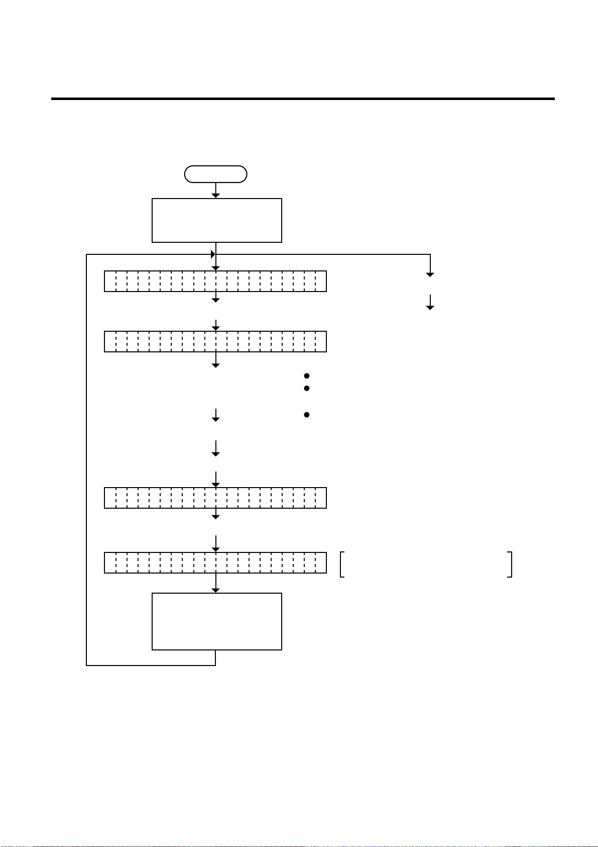
6.2.2 Automatic Diagnostic Printing
The data from 1 to 9 on a sample print is printed.
Power off
Turn on the power while
holding down the [FEED]
key and [PAUSE] key.
EM18-33013
6.2 SLEF TEST MODE
<1 DIAGNOSTI C V1.OA>
Press the [PAUSE] key.
RI BON TRANSMISSIVEB
Select the ribbon type from those
at the right by pressing the
[FEED] key or [RESTART] key.
Press the [PAUSE] key.
Press the [FEED] key.
AU OMATIC DIAGNOSTICT
Press the [PAUSE] key.
CH CKING & PRINTINGE
Press the [PAUSE] key.
Continued on Section 6.2.3
Head Broken Element Check.
NO RIBBON (No ribbon : Thermal direct)
TRANSMISSIVE
(Transmissive ribbon : Thermal transfer)
NO TRANS.
(Non-transmissive ribbon : Thermal transfer)
The printer is checking or printing
the status
The result of the self test
is printed. After printing,
the initial display will be
shown.
NOTES: 1. If the automatic diagnosis printing results in an error, the printer will display the error
message and stop printing. The error status can be cleared by the [PAUSE] key,
however, the display will return to the initial display “<1> DIAGNOSTIC V1.0A”.
Printing is not automati cally resumed.
2. Both label and tag paper can be used for printing.
6-6
Page 36
6. DIAG. TEST OPERATION
EM18-33013
6.2 SELF TEST MODE
■ Sample Print
[Print Condition]
• Preset count : 1
• Print speed : 101.6 mm/sec.
• Sensor : No sensor
• Printing method : Thermal transfer
• Supply length : 50 mm
• Issuing mode : Batch printing
(without rewinder)
Fig. 6-2
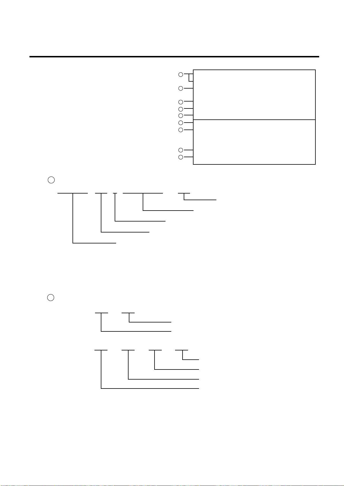
1 PROGRAM/MASK ROM Check
PROGRAM V1.0 A FMRM0034801
1
PROGRAM V1.OA FMRM0034801:2800
MASK V1.0 FMRM0034901:B100
2
KANJI 0000:0000
0000:0000:0000:0000
3
EEPROM OK
4
DRAM 1024KB
5
CARD OK
6
SENSOR1 00000000,10110011
7
SENSOR2 [H]3.1V [A]2.8V
[R]3.3V [T]2.4V
[RANK]3
8
DIP SW 00000000,10001010
9
EXP.I/O OK
2800:
Part No. of ROM of software
Revision No.: Space or A to Z
Software version No.
Checksum
ROM name
PROGRAM: Program ROM (Flash ROM)
MASK: Mask ROM (Character generator)
NOTES: 1. Software version No., part No. of ROM and checksum very according to the software
version of PROGRAM/MASK ROM.
2. The last two digits of the checksum are usually 0.
2 KANJI ROM Check
KANJI
0000 0000
0000
:
0000 0000 0000
:::
KANJI ROM2 Checksum
KANJI ROM1 Checksum
KANJI OUTLINE ROM4 Checksum
KANJI OUTLINE ROM3 Checksum
KANJI OUTLINE ROM2 Checksum
KANJI OUTLINE ROM1 Checksum
NOTES: 1. Checksum varies according to the software version.
2. When the KANJI ROM or KANJI OUTLINE ROM is not installed, the checksum
because “0000”.
3. The last two digits of the checksum are not 0.
6-7
Page 37
6. DIAG. TEST OPERATION
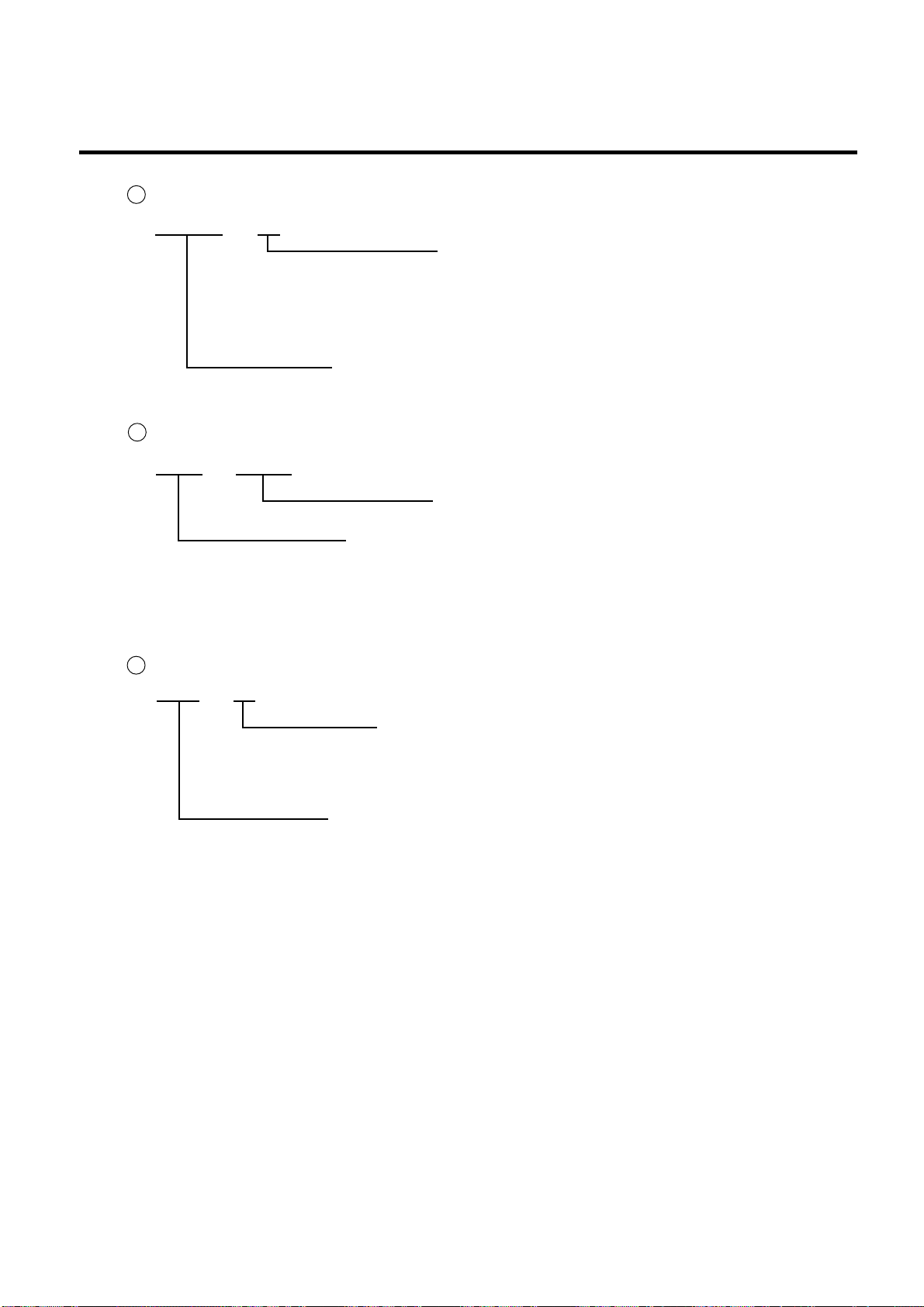
3 EEPROM Check
EEPROM OK
4 DRAM Check
DRAM 1024KB
EM18-33013
6.2 SELF TEST MODE
Read/write check
OK: Data in the check area can be properly
read/written.
NG: Data in the check area cannot be
properly read/written.
EEPROM: Backup memory
Readable/writable area
DRAM: Image buffer memory or work memory
NOTE: If an error is detected during DRAM check, the display od readable/writable area will stop
when the error occurs.
5 Flash Memory Card Check
CARD OK
Format check
OK: Formatted
NG: Formatted improperly or no flash
memory card is inserted.
Flash memory card
6-8
Page 38

6. DIAG. TEST OPERATION
6 Sensor 1 Check
EM18-33013
6.2 SELF TEST MODE
SENSOR1
00000000, 10110011
Head up switch status
0: Head opened
1: Head closed
Fixed to 1
Cutter home position switch status
0: Home position
1: Other position
Rewind full sensor status
0: Normal
1: Excess
Slit sensor #1 (ribbon rewind) status
0: The detecting point is positioned
outside the slit.
1: The detecting point is positioned
inside the slit.
Slit sensor #2 (ribbon feed) status
0: The detecting point is
positioned outside the slit.
1: The detecting point is
positioned inside the slit.
Fixed to 0
Strip sensor status
0: Without label
1: With label
Ribbon end sensor status
0: Transmissive (with ribbon)
1: Non-transmissive (ribbon end)
Fixed to 0
6-9
Page 39
6. DIAG. TEST OPERATION
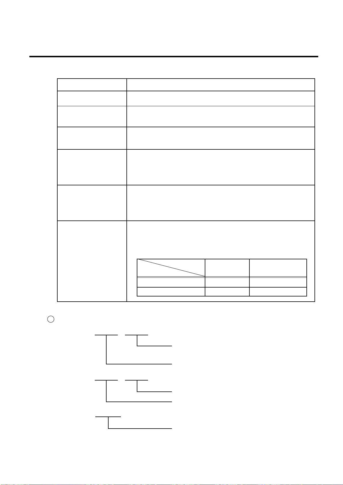
■ Print status content description of each sensor/switch
EM18-33013
6.2 SELF TEST MODE
Sensor/Switch
Head up switch
Cutter home position
switch
Rewind full sensor
Slit sensor #1 (ribbon
rewind)
Slit sensor #2 (ribbon
feed)
Strip sensor
Ribbon end sensor
Print status content description
Indicates whether the print head is opened or closed.
Indicates whether the cutter is at the home position or not.
Indicates whether the media is wound to peak capacity on the builtin take-up spool or not.
Controls ribbon motor rotation by detecting the slit on the ribbon
rewind motor and the ribbon feed motor. Indicates the position to
the slit sensor.
Indicates the existence of label in strip mode. When no label is
detected (0), the subsequent label is issued, when a label is
detected (1), the subsequent label will not be issued until the current
label is removed.
The display of the ribbon end sensor only shows whether the ribbon
is transmissive or non-transmissive. The status of the ribbon end
detection differs according to the parameter setting. The following
table shows the parameter settings in the parameter setting mode.
7 SENSOR2 Check
SENSOR2 [H] 3.1V [A] 2.8V
[R] 3.3V [T] 2.4V
[RANK 3]
Type of ribbon
Transmissive
Ribbon end sensor
Non-transmissive
Transmissive With ribbon Ribbon end
Non-transmissive Ribbon end With ribbon
Environmental temperature thermistor status:
0.0 ~ 5.0 V
Print head thermistor status: 0.0 ~ 5.0 V
Feed gap sensor status: 0.0 ~ 5.0 V
Black mark sensor status: 0.0 ~ 5.0 V
Print head resistance rank: 0 ~ 15
6-10
Page 40
6. DIAG. TEST OPERATION
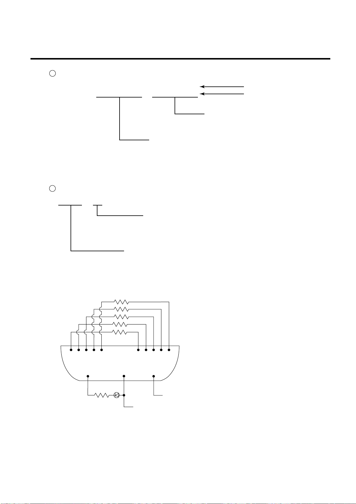
8 DIP SW Check
EM18-33013
6.2 SELF TEST MODE
DIP SW
87654321
00000000
87654321
10001010
Pin No.
Status
DIP Switch 2
0: OFF (OPEN)
1: ON (SHORT)
DIP Switch 1
0: OFF (OPEN)
1: ON (SHORT)
NOTE: The DIP switch 1-7 is to be set to 0 (OFF:OPEN) regardless of setting item.
9 EXP. I/O Check
EXP. I/O
OK
Loopback test
OK: The circuit has no problem.
NG: The circuit has a problem or loopback jig
is not attached.
Expansion I/O PC board
For the loopback test, connect jig as shown below and check HIGH output / HIGH input and
LOW output / LOW input.
300Ω x 5
1 2 3 4 5 7 8 9 10 11
12
300Ω
15
21
GND
Vcc
Connecter: FCN-781P024-G/P
Fig. 6-3
6-11
Page 41
6. DIAG. TEST OPERATION
6.2 SELF TEST MODE
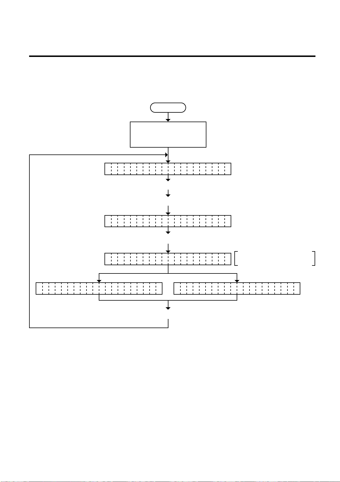
6.2.3 Head Broken Element Check
The printer automatically performs the head broken element check. The result of the head broken
element check is indicated in the display.
Power off
Turn on the power while
holding down the [FEED]
key and [PAUSE] key.
<1 DIAGNOSTI C V1.OA>
Press the [PAUSE] key twice.
EM18-33013
Press the [FEED] key twice.
TH RMAL HEAD CHECKE
Press the [PAUSE] key.
CH CKINGE
Head broken element check
takes about 10 seconds.
NO MAL ENDR HE D ERRORA
(See NOTE 1 and 2.)
Press the [PAUSE] key.
NOTES: 1. If the head broken element check results in ‘HEAD ERROR’, the print head must be
replaced after referring to Section 2.6 Replacing the Print Head.
2. After replacing the print head, clear the maintenance counter as described in Section
6.6.1 and perform a test print in Section 6.4 TEST PRINT MODE.
6-12
Page 42
6. DIAG. TEST OPERATION
(Revision Date: Dec. 10 ‘99)
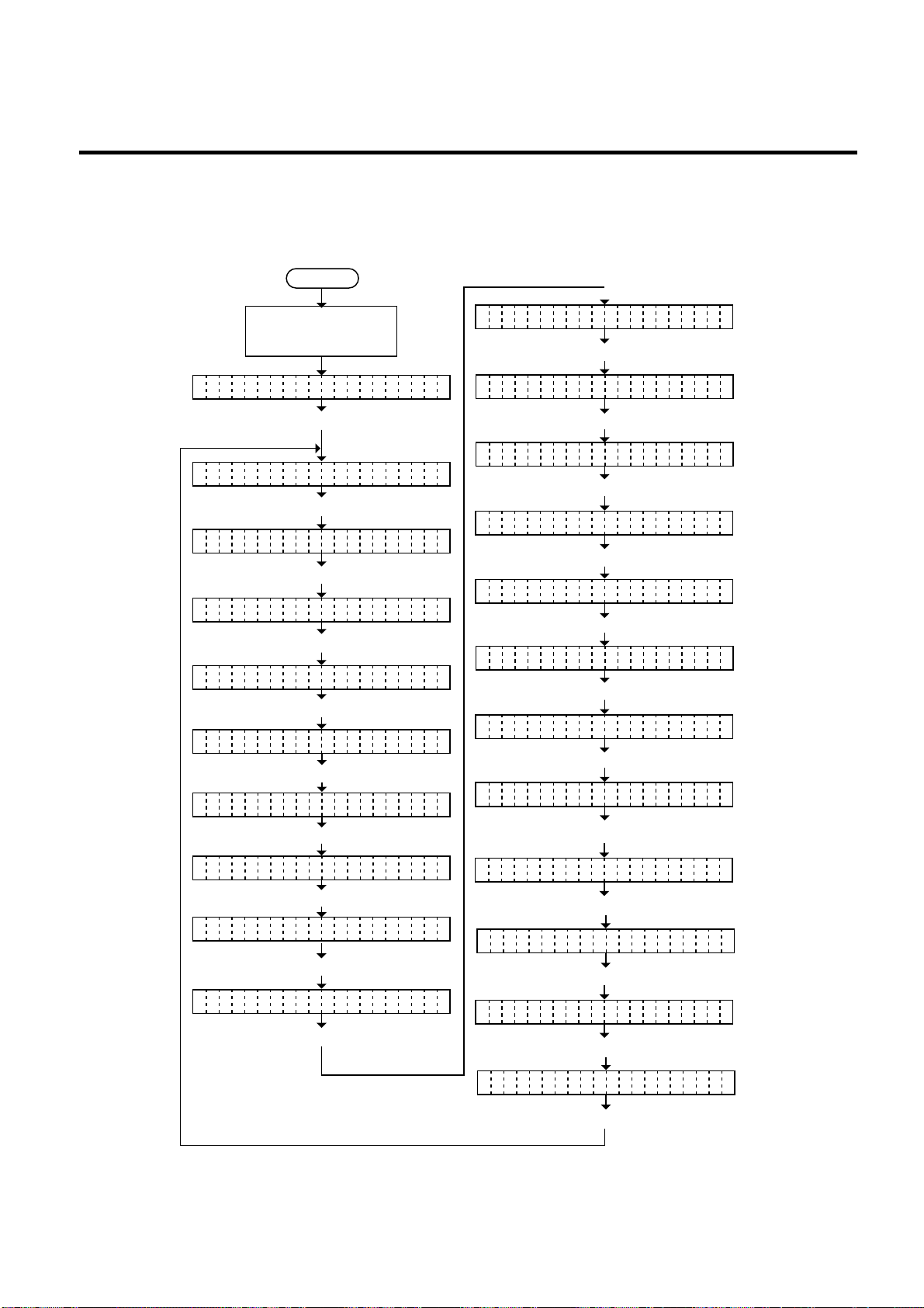
6.3 PARAMETER SETTING MODE
EM18-33013
6.3 PARAMETER SETTING MODE
The following items are set in the parameter setting mode. The values set in this mode are printed on
the sample print of the maintenance counter. Setting procedure and functions are provided below.
Power off
Turn on the power while
holding down the [FEED]
key and [PAUSE] key.
<
>
1 DIAGNOSTIC V1.0A
Press the [FEED] key.
<
>
2 PARAMETER SET
Press the [PAUSE] key.
E D ADJUST +0.0mmE
F
Press the [PAUSE] key.
U ADJUST +0.0mmT
C
Press the [PAUSE] key.
A K FEED ADJ.+0.0mmC
B
Press the [PAUSE] key.
DJUST +0.0mmA
X
Press the [PAUSE] key.
O E ADJU ST <T> +0N
T
Press the [PAUSE] key.
O E AUTOD
C
Press the [PAUSE] key.
I BON TRANS.B
R
Press the [PAUSE] key.
I BON ADJ <FWS> +0B
R
Press the [PAUSE] key.
I BON ADJ <BAK> +0B
R
Press the [PAUSE] key.
T TUS TYPE 1A
S
Press the [PAUSE] key.
H ESHOLD R 1.0VR
T
Press the [PAUSE] key.
H ESHOLD T 1.4VR
T
Press the [PAUSE] key.
A JI CODE TYPE1N
K
Press the [PAUSE] key.
O E ADJU ST <D> +0N
T
Press the [PAUSE] key.
O T CODE PC-850N
F
Press the [PAUSE] key.
E O FONT 0R
Z
Press the [PAUSE] key.
U O CODE BO HR
E
Press the [PAUSE] key.
E D TYPE1A
H
Press the [PAUSE] key.
T /RTS DTRR
D
Press the [PAUSE] key.
N UT PRIME ONP
I
Press the [PAUSE] key.
6-13
Page 43

6. DIAG. TEST OPERATION
■ Parameter Setting Mode Table
(Revision Date: Dec. 10 ‘99)
EM18-33013
6.3 PARAMETER SETTING MODE
Mode Name
FEED ADJUST
CUT ADJUST
BACK FEED ADJ.
X ADJUST
TONE ADJUST <T>
(Thermal transfer printing)
TONE ADJUST <D>
(Thermal direct printing)
FONT CODE
ZERO FONT
CODE
RIBBON
RIBBON ADJ <FWD>
(Ribbon feed motor)
RIBBON ADJ <BAK>
(Ribbon feed motor)
Function
Using this parameter the feed length is fine adjusted.
Using this parameter the cut position or strip position is fine adjusted.
Using this parameter the back feed length from the cut/strip position to the
home position is fine adjusted.
This setting is used to finely adjust print position in the X axis.
Using this parameter the print tone is fine adjusted. The longer the print
pulse width, the darker the print tone becomes. The shorter, the lighter
the print tone becomes.
The character code either PC-850 or PC-8 is selected.
The font zero either 0 or ø is selected.
The command code out of AUTO, ESC/LF/NUL, or { } is selected.
Ribbon type either transmissive or non-transmissive is selected.
Using this parameter the torque of the ribbon motors is fine adjusted.
STATUS TYPE
THRESHOLD R
THRESHOLD T
KANJI CODE
EURO CODE
HEAD
DTR/RTS
INPUT PRIME
Whether or not the strip wait status (05H) is sent in response to the status
request command from the PC is selectable.
The threshold of the black mark sensor is manually fine adjusted.
The threshold of the feed gap sensor is manually fine adjusted.
Kanji code either Windows code or original code is selected.
(not supported by QQ/QP models.)
EURO code is selected from 20H to FFH.
Type of the print head is selected.
Transmission Control Mode is selected from DTR or RTS.
Reset ON/OFF when the INPUT • PRIME signal on is selected.
6-14
Page 44
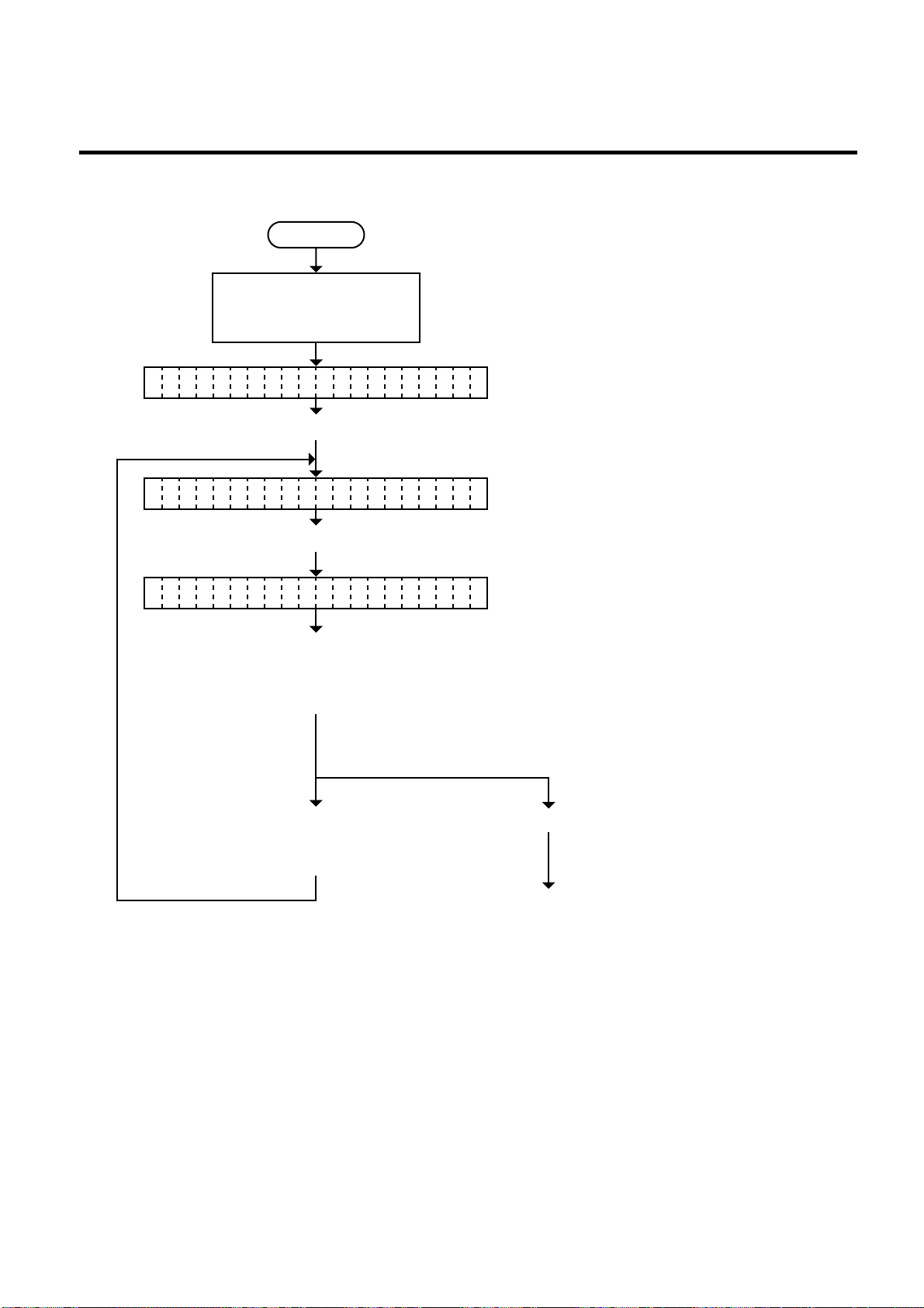
6. DIAG. TEST OPERATION
6.3.1 Feed Length Fine Adjustment
Power off
Turn on the power while
holding down the [FEED]
key and [PAUSE] key.
<1 DIAGNOSTI C V1.OA>
Press the [FEED] key.
<2 PARAMETER SET>
EM18-33013
6.3 PARAMETER SETTING MODE
Press the [PAUSE] key.
FE D ADJUST +0.0mmE
Press the [FEED] or
[RESTART] key to adjust
the feed length.
(See NOTE 1.)
Press the [FEED] key
Press the [PAUSE] key.
■ [FEED] key: Pressing the [FEED] key one
time is a -0.5 mm change, up
to -50.0 mm. (See NOTE 2.)
■ [RESTART] key: Pressing the [RESTART] key
one time is a +0.5 mm change,
up to +50.0 mm.
(See NOTE 2.)
and [RESTART] key
at the same time.
Continued on Section 6.3.2
Cut/strip position fine adjustment.
NOTES: 1. Holding the [FEED] key or [RESTART] key down for more than 0.5 seconds enables
a fast forward.
2. Max. fine adjustment
±
50.0 mm = Key fine adjustment value (± 50.0 mm) + PC fine
adjust ment value (± 50.0 mm)
When the value reaches the maximum, the value remains unchanged even if the
subsequent fine adjustment is performed.
3. A change feed value is stored in memory by pressing the [PAUSE] key.
6-15
Page 45

6. DIAG. TEST OPERATION
6.3.2 Cut/Strip Position Fine Adjustment
Power off
Turn on the power while
holding down the [FEED]
key and [PAUSE] key.
<1 DIAGNOSTI C V1.OA>
Press the [FEED] key.
<2 PARAMETER SET>
EM18-33013
6.3 PARAMETER SETTING MODE
Press the [PAUSE] key twice.
CU ADJUST +0.0mmT
Press the [FEED] or
[RESTART] key to adjust
the feed length.
(See NOTE 1.)
Press the [FEED] key
■ [FEED] key: Pressing the [FEED] key one
time is a -0.5 mm change, up to
-50.0 mm. (See NOTE 2.)
■ [RESTART] key: Pressing the [RESTART] key
one time is a +0.5 mm change,
up to +50.0 mm. (See NOTE2.)
Press the [PAUSE] key.
and [RESTART] key
at the same time.
Continued on Section 6.3.3
Back feed length fine adjustment.
NOTES: 1. Holding the [FEED] key or [RESTART] key down for more than 0.5 seconds enables
a fast forward.
2. Max. fine adjustment
±
50.0 mm = Key fine adjustment value (±50.0 mm) + PC fine
adjustment value ( ± 50.0 mm)
When the value reaches the maximum, the value remains unchanged even if a
subsequent fine adjustment is performed.
3. A changed cut/strip position value is stored in memory by pressing the [PAUSE] key.
4. When using label with length of less than 38 mm, calculate the cut position fine
adjustment value using the expression provided on page 6-19.
6-16
Page 46
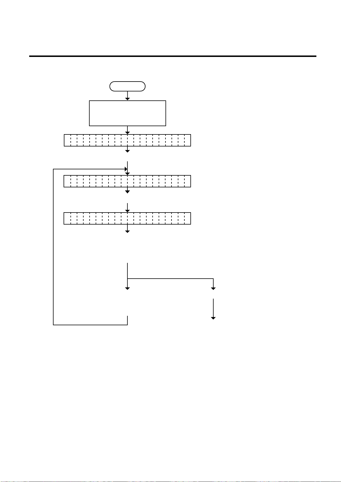
6. DIAG. TEST OPERATION
6.3.3 Back Feed Length Fine Adjustment
Power off
Turn on the power while
holding down the [FEED]
key and [PAUSE] key.
<1 DIAGNOSTI C V1.OA>
Press the [FEED] key.
<2 PARAMETER SET>
EM18-33013
6.3 PARAMETER SETTING MODE
Press the [PAUSE] key three times.
BA K FEED ADJ.+0.0mmC
Press the [FEED] or
[RESTART] key to adjust
the feed length.
(See NOTE 1.)
Press the [FEED] key
■ [FEED] key: Pressing the [FEED] key one
time is a -0.5 mm change, up to
-9.5 mm. (See NOTE 2.)
■ [RESTART] key: Pressing the [RESTART] key
one time is a +0.5 mm change,
up to +9.5 mm. (See NOTE 2.)
Press the [PAUSE] key.
and [RESTART] key
at the same time.
Continued on Section 6.3.4
X axis fine adjustment.
NOTES: 1. Holding the [FEED] key or [RESTART] key down for more than 0.5 seconds enables
a fast forward.
2. Max. fine adjustment
±
9.9 mm = Key fine adjustment value (± 9.5 mm) + PC fine
adjustment value (±9.9 mm)
When the value reaches the maximum, the value remains unchanged even if the
subsequent fine adjustment is performed.
3. A changed back feed value is stored in memory by pressing the [PAUSE] key.
6-17
Page 47
6. DIAG. TEST OPERATION
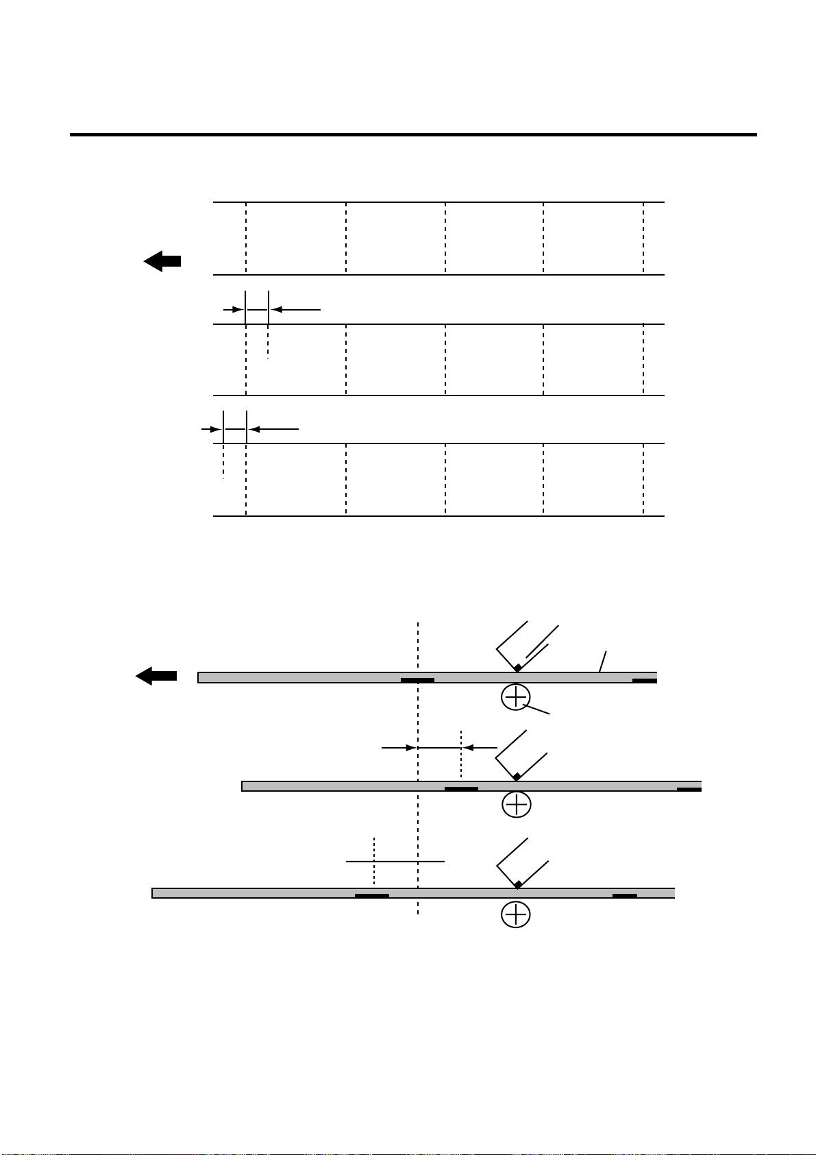
■ Feed Length Fine Adjustment Example
+ 0.0 mm
Feed Direction
- 10 mm
- 10.0 mm
A
A
6.3 PARAMETER SETTING MODE
A
EM18-33013
A
Fig. 6-4
A
+ 10 mm
+ 10.0 mm
A
■ Cut Position Fine Adjustment Example
+ 0.0 mm
Feed Direction
Black Mark
- 12.0 mm
Cut Position
A
A
- 12 mm
A
A
Print Head
Platen
A
A
Tag Paper
Fig. 6-5
Fig. 6-6
Fig. 6-7
+ 12.0 mm
Fig. 6-8
- 12 mm
Fig. 6-9
6-18
Page 48

6. DIAG. TEST OPERATION
■ When using a label with a length of less than 38 mm :
Case 1
Condition: Issue command [ESC]XS, feed command [ESC]T and eject command [ESC]IB
are received.
Label pitch: 38.0 mm or less, with cut, feed gap sensor, cut position fine adjustment value ±
10 mm or less, and issue mode set to C (cut). When the above conditions are all met, the issue
operation in cut issue mode is as follows:
Head lifted → Forward feed to the cut position → Head lowered → Cut →
Head lifted → Backfeed to the home position → Head lowered.
Case 2
Generally the minimum label length which is available in cut mode is 38.0 mm. When using a
label with a length of less than 38 mm, the edge of the label may be caught on the print head
during back feed to the print start position after cutting the label gap, causing a improper print
start position.
In this case set the cut position fine adjustment value after calculating the value using the
following formula so that the unprinted label returns to the correct print start position.
However, use of this method will leave one or two printed label(s) between the print head and
the cutter. Feed or print the label(s) to remove them.
(Revision Date Sep. 27, ’95)
EM18-33013
6.3 PARAMETER SETTING MODE
(a) Formula for cut position the adjustment value
Cut position fine adjustment value
= (the number of labels left between the print head and the cutter) x (span of label)
= (32.8 mm/label length) x (span of label)
* Omit the decimals of the value obtained by dividing 32.8 mm by the label length for one
unit.
(example) Span of label : 30.0 mm, Label length : 24.0 mm
(32.8 mm/30.0 mm) x 30.0 mm = 1 x 30.0 mm = +30.0 mm
(b) Example
Cut Position Print Head Position
32.8 mm
A B
A
A
A
A
A
A
B
B
B
B
B
B
C
C
C
B
B
B
C
C
C
D
D
D
Idling
Printing the first label (A) is completed.
Label A is fed to the cut position and the front gap
is cut.
Label B is fed in the reverse direction to the print
start position.
Printing the second label (B) is completed.
Label B is fed to the cut position and the front gap
is cut.
Label C is fed in the reverse direction to the print
start position.
To take away label B, label (C) is fed.
Label B is fed to the cut position and the front gap
is cut.
0
Label D is fed in the reverse direction to the print
start position.
Fig. 6-10 Print Start Position
6-19
Page 49
6. DIAG. TEST OPERATION
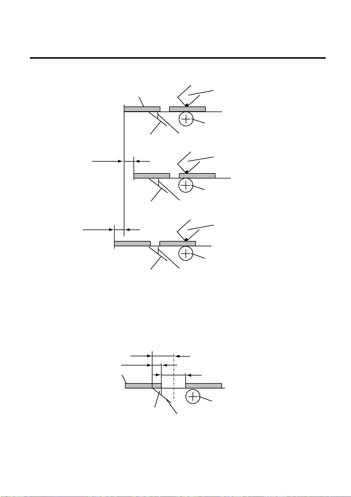
■ Strip Position Fine Adjustment Example
EM18-33013
6.3 PARAMETER SETTING MODE
+ 0.0 mm
+ 3.0 mm
- 3.0 mm
- 3.0 mm
+ 3.0 mm
Label
Backing Paper
Backing Paper
Strip Shaft
Strip Shaft
Print Head
Platen
Print Head
Platen
Print Head
Platen
Fig. 6-11
Fig. 6-12
Fig. 6-13
Backing Paper
Strip Shaft
NOTE: The print stop position when printing the label in strip mode varies according to label length
for the strip mode printing stops so that the edge of the strip shaft is 4 mm from the middle
of the gap. This is because the gap length is programmed as 2mm. When the gap length
is 5 mm or more, the effective print length should be set to the value obtained by
subtracting 2 mm from the label pitch, that is, set the gap length to 2 mm. If the print format
hangs over the gap as a result, correct the print start position. If the print stop position is
improper, refer to Section 6.3.2 and make a fine adjustment.
4 mm
3 mm
Label
Strip Shaft
2 mm
Backing Paper
Platen
Fig. 6-14
6-20
Page 50
6. DIAG. TEST OPERATION
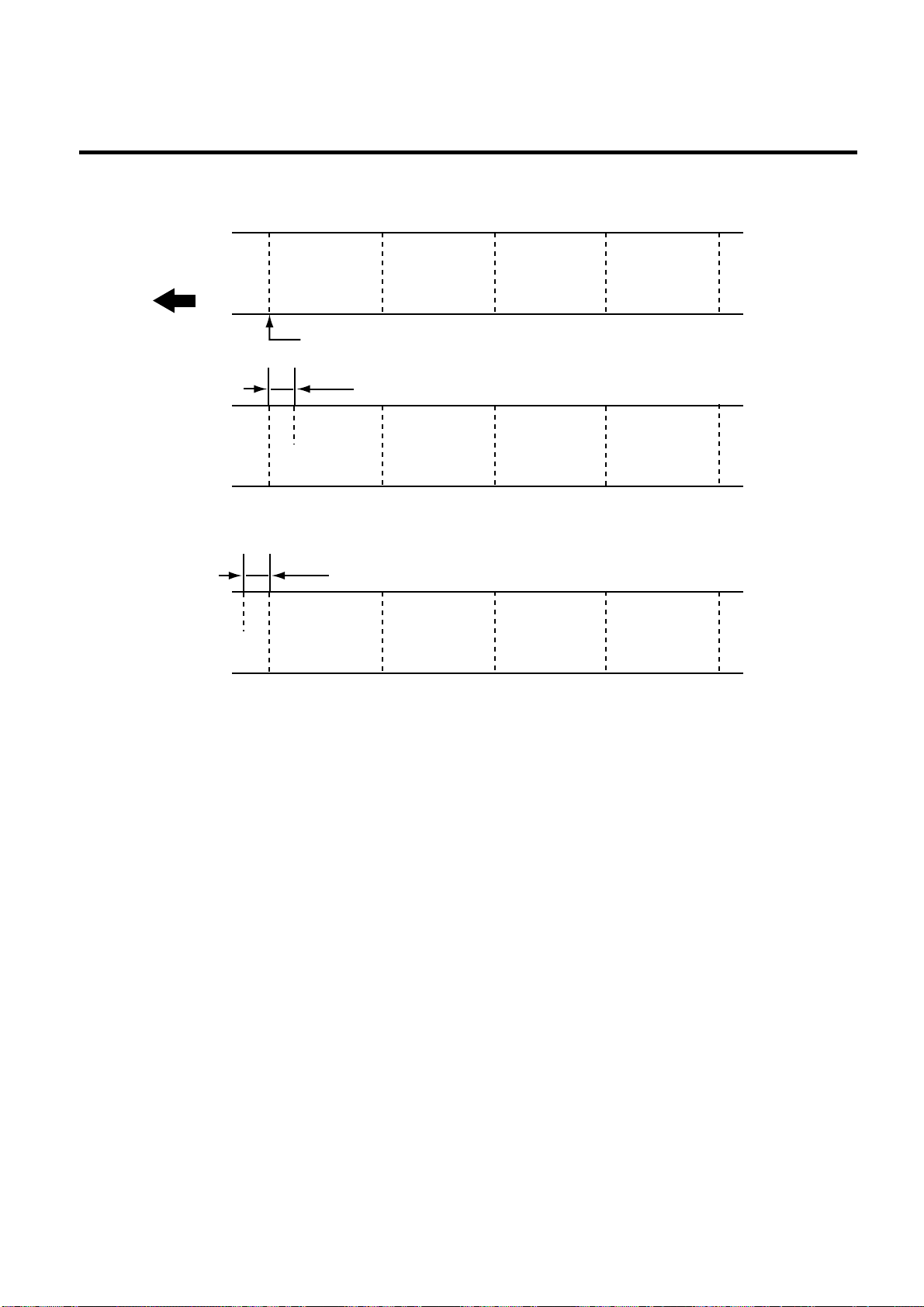
■ Back Feed Length Fine Adjustment Example
+ 0.0 mm
Feed Direction
A
Print start position
+3.0 mm
+3.0 mm
A
6.3 PARAMETER SETTING MODE
A
EM18-33013
A
Fig. 6-15
-3.0 mm
-3.0 mm
A
A
A
A
A
A
A
A
Fig. 6-16
Fig. 6-17
6-21
Page 51
6. DIAG. TEST OPERATION
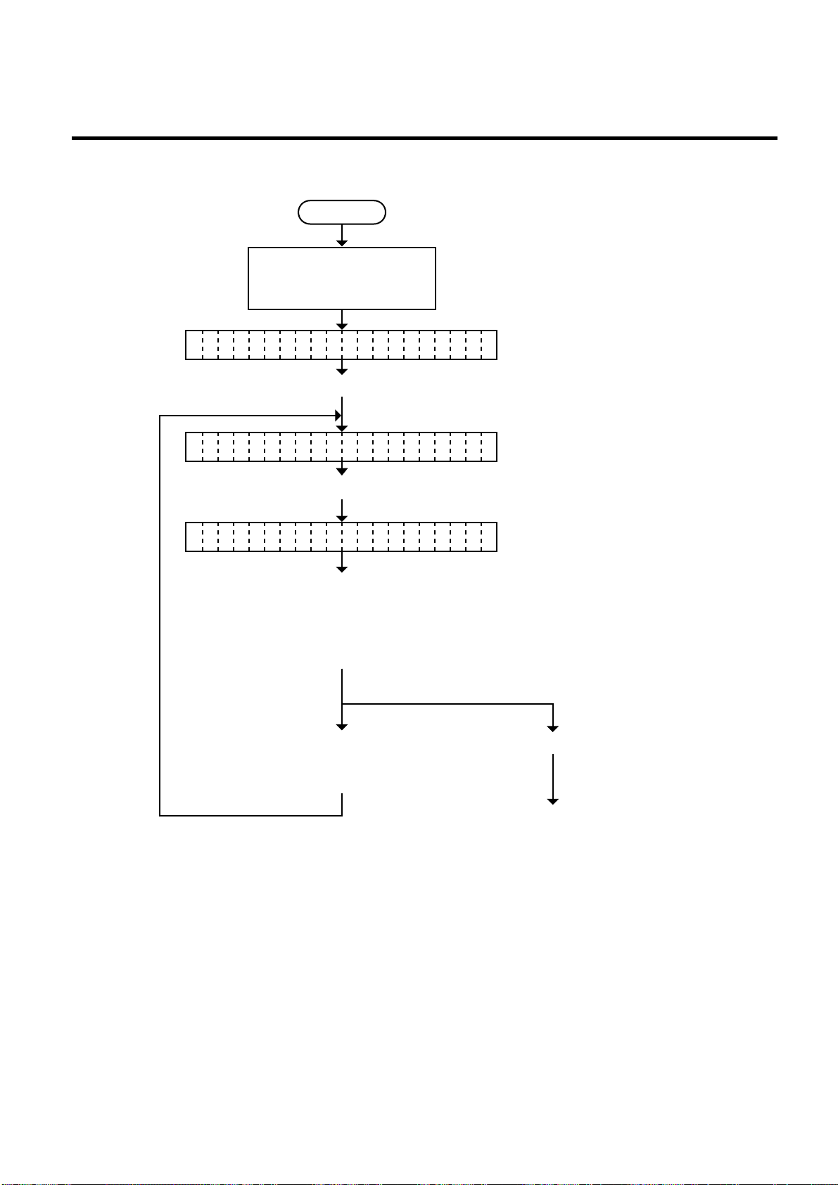
6.3.4 X Axis Fine Adjustment
Turn on the power while
holding down the [FEED]
key and [PAUSE] key.
<1 DIAGNOSTI C V1.OA>
Press the [FEED] key.
<2 PARAMETER SET>
EM18-33013
6.3 PARAMETER SETTING MODE
Power off
Press the [PAUSE] key four times.
X DJUST +0.0mmA
Press the [FEED] or
[RESTART] key to fine
adjust the print position
along the X axis.
(See NOTE 1.)
Press the [FEED] key
■ [FEED] key: Pressing the [FEED] key one
time is a -0.5 mm change, up to
-99.5 mm. (See NOTE 2.)
■ [RESTART] key: Pressing the [RESTART] key
one time is a +0.5 mm change,
up to +99.5 mm. (See NOTE 2.)
Press the [PAUSE] key.
and [RESTART] key
at the same time.
Continued on Section 6.3.5
Print tone fine adjustment.
NOTES: 1. Holding the [FEED] key or [RESTART] key down for more than 0.5 seconds enables
a fast forward.
2. Max fine adjustment
±
99.5 mm = X axis value
When the value reaches the maximum, the value remains unchanged even if the
subsequent fine adjustment is performed.
3. A changed X axis is stored in memory by pressing the [PAUSE] key.
6-22
Page 52
6. DIAG. TEST OPERATION
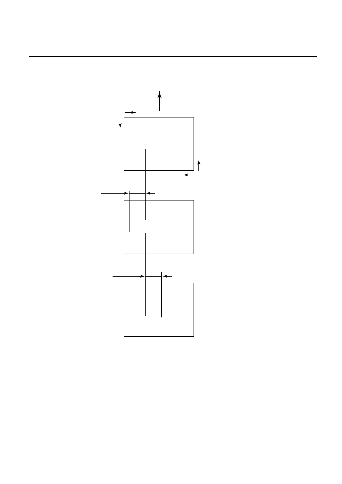
■ X axis Fine Adjustment Example
EM18-33013
6.3 PARAMETER SETTING MODE
Feed direction
To down printing
+0.0 mm
-50.0 mm
-50.0 mm
Y
ABC
+ 50.0 mm
X
ABC
Fig. 6-18
Y
X
Bottom first printing
Fig. 6-19
+50.0 mm
Fig. 6-20
ABC
NOTES: 4. The X axis fine adjustment is performed to fine adjust the X axis of the drawing in the
left or right direction.
5. Adjust the X axis in the effective print range. (After the value reaches the coordinate
“0”, the value remains unchanged even if the subsequent fine adjustment is
performed in the negative direction.)
6. X axis fine adjustment cannot be used in self test mode or test printing.
6-23
Page 53
6. DIAG. TEST OPERATION
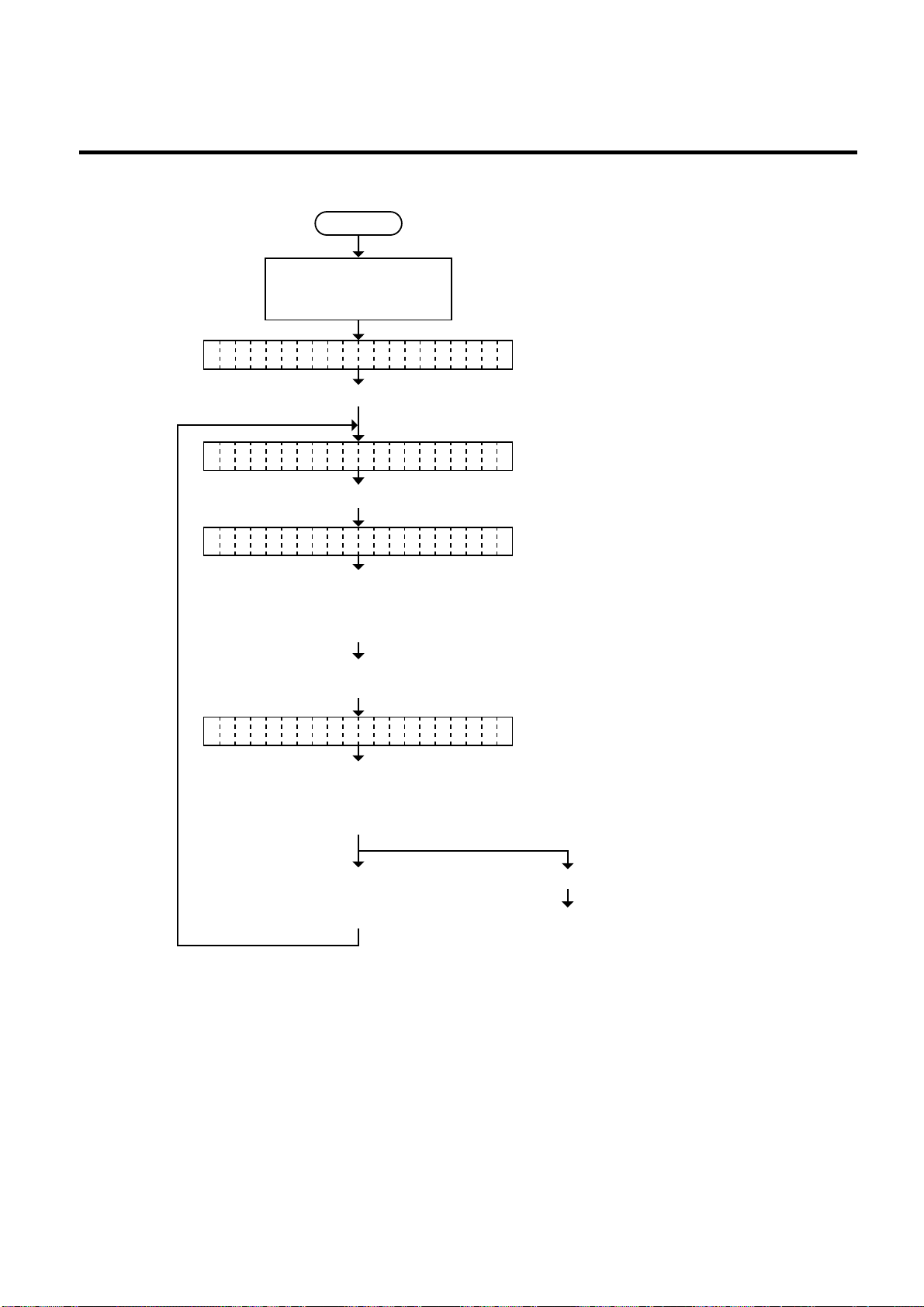
6.3.5 Print Tone Fine Adjustment
Power off
Turn on the power while
holding down the [FEED]
key and [PAUSE] key.
<1 DIAGNOSTIC V1.OA>
Press the [FEED] key.
<2 PARAMETER S ET>
Press the [PAUSE] key five times.
(Revision Date: Jan. 14 ’99)
EM18-33013
6.3 PARAMETER SETTING MODE
TO E ADJUST <T> +0N
TO E ADJUST <D> +0N
Press the [FEED] or
[RESTART] key to adjust
the feed length.
(See NOTE 1.)
Press the [PAUSE] key.
(See NOTE 3.)
Press the [FEED] or
[RESTART] key to fine
adjust the print tone.
(See NOTE 1.)
Press the [FEED] key
and [RESTART] key
at the same time.
Continued on Section 6.3.6
Character code selection.
(Thermal transfer printing fine adjustment)
■ [FEED] key: Pressing the [FEED] key one
time is a -1 step change, up to
-10 steps. (See NOTE 2.)
■ [RESTART] key: Pressing the [RESTART] key
one time is a +1 step change,
up to +10 steps. (See NOTE 2.)
(Thermal direct printing fine adjustment)
■ [FEED] key: Pressing the [FEED] key one
time is a -1 step change, up to
-10 steps. (See NOTE 2.)
■ [RESTART] key: Pressing the [RESTART] key
one time is a +1 step change,
up to +10 steps. (See NOTE 2.)
Press the [PAUSE] key .
NOTES: 1 Holding the [FEED] key or [RESTART] key down for more than 0.5 seconds enables
a fast forward.
2. A changed print tone value is stored in memory by pressing the [PAUSE] key.
3. Fine adjustment value equals to the sum of the values set by the PC command and
system mode (key operation) and each max. value is
±
10 step. However, the upper
limit of the adjustment value is decided according to the print speed to protect the print
head. If the set value exceeds the following upper limit, it is automatically corrected
to the proper value.
Upper Limit: 3”/sec.: +10 step, 4”/sec.: +5 step, 8”/sec.: +2 step.
6-24
Page 54

6. DIAG. TEST OPERATION
6.3.6 Character Code Selection
<1 DIAGNOSTI C V1.OA>
<2 PARAMETER SET>
EM18-33013
6.3 PARAMETER SETTING MODE
Power off
Turn on the power while
holding down the [FEED]
key and [PAUSE] key.
Press the [FEED] key.
Press the [PAUSE] key seven times.
FO T CODE PC-850N
• PC-850
Select either chracter code with
• PC-8
the [FEED] key or [RESTART]
Key.(See NOTE1.)
Press the [FEED] key
Press the [PAUSE] key .
and [RESTART] key
at the same time.
Continued on Section 6.3.7
Font zero selection.
NOTES: 1. Holding the [FEED] key or [RESTART] key down for more than 0.5 seconds enables
a fast forward.
2. A changed font code is stored in memory by pressing the [PAUSE] key.
6-25
Page 55
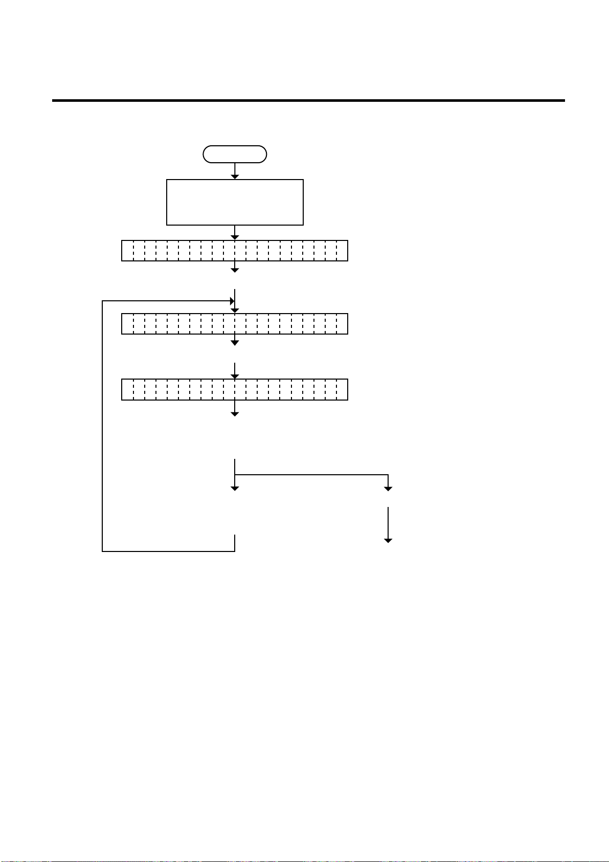
6. DIAG. TEST OPERATION
6.3.7 Font Zero Selection
Turn on the power while
holding down the [FEED]
key and [PAUSE] key.
<1 DIAGNOSTI C V1.OA>
Press the [FEED] key.
<2 PARAMETER SET>
EM18-33013
6.3 PARAMETER SETTING MODE
Power off
Press the [PAUSE] key eight times.
ZE O FONT 0R
Select either zero font with the
[FEED] key or [RESTART]
• 0 (without slash)
• ø (with slash)
key. (See NOTE 1.)
Press the [FEED] key
Press the [PAUSE] key .
and [RESTART] key
at the same time.
Continued on Section 6.3.8
Control code selection
NOTES: 1. Holding the [FEED] key or [RESTART] key down for more than 0.5 seconds enables
a fast forward.
2. A changed zero font is stored in memory by pressing the [PAUSE] key.
6-26
Page 56
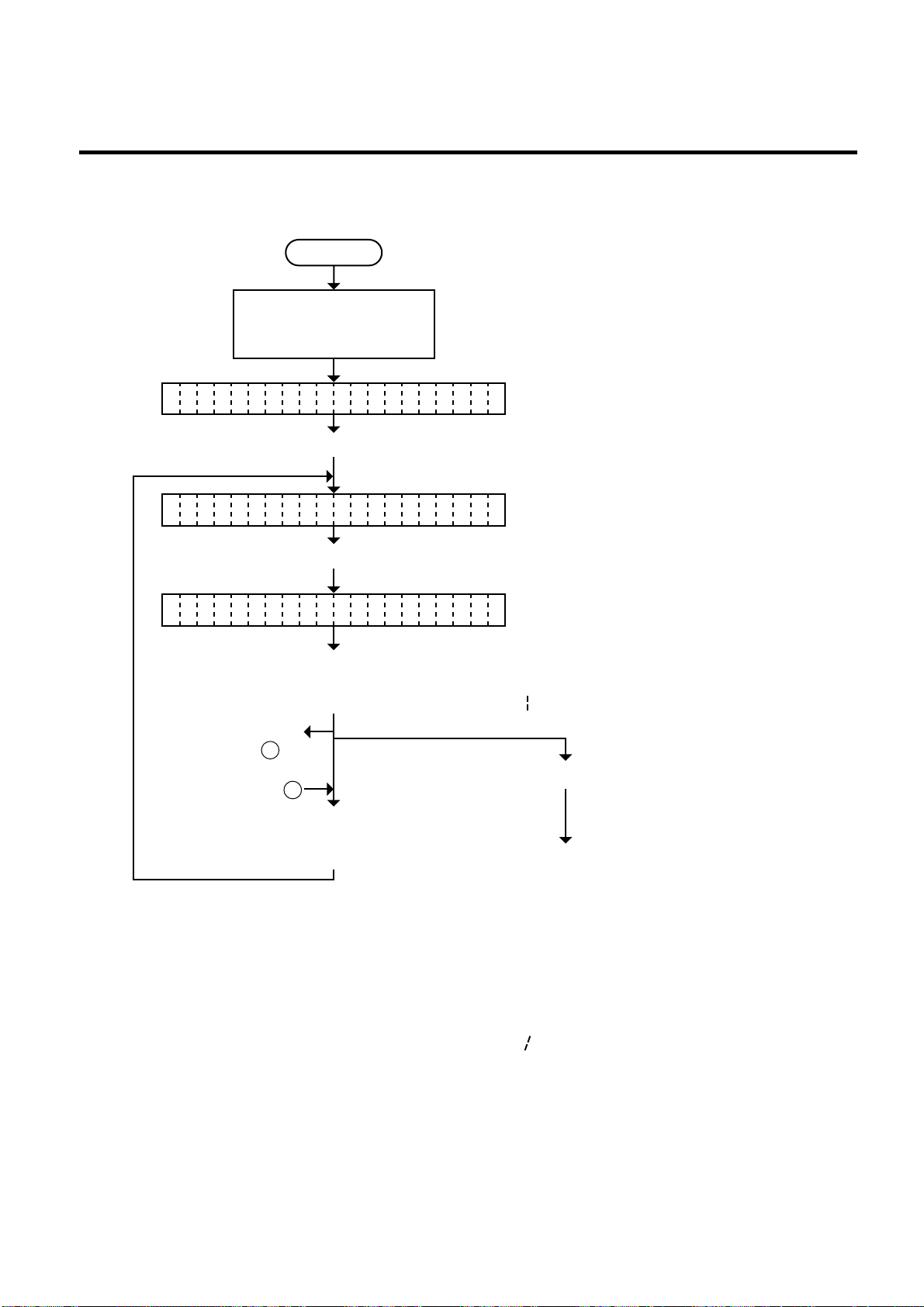
6. DIAG. TEST OPERATION
6.3.8 Control Code Selection
Power off
Turn on the power while
holding down the [FEED]
key and [PAUSE] key.
<
>
1 DIAGNOSTIC V1.OA
Press the [FEED] key.
<
>
2 PARAMETER SET
SVO8A1002 : Jan. 19, '98
EM18-33013
6.3 PARAMETER SETTING MODE
Press the [PAUSE] key nine times.
CO E AUTOD
Select control code with the
[FEED] key or [RESTART]
key. (See NOTE 1.)
When {MANUAL} is
• AUTO: (Automatic selection)
• ESC, LF, NUL: (Manual selection)
• { , , } : (Manual selection)
• MANUAL: (control codes should be specified.)
selected, go to A
on the next page.
Press the [PAUSE] key.
B
Press the [FEED] key
and [RESTART] key
at the same time.
Continued on Section 6.3.9
Ribbon type selection.
NOTES: 1. Holding the [FEED] key or [RESTART] key down for more than 0.5 seconds enables
a fast forward.
2. A changed control code is stored in memory by pressing the [PAUSE] key.
3. When “AUTO”, “ESC, LF, NUL”, or “{, ,}” is selected, be sure to select the Nontransmissive ribbon in the ribbon type selection operation.
4. When “MANUAL” is selected, be sure to specify all the control codes 1 to 3. Failure
to do this disables selection of “MANUAL”.
6-27
Page 57
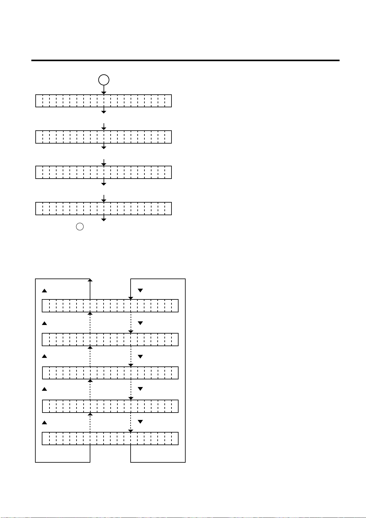
6. DIAG. TEST OPERATION
A
SVO8A1002 : Jan. 19, '98
EM18-33013
6.3 PARAMETER SETTING MODE
O E MANUAL
C
D
Change the control code.
Press the [PAUSE] key.
C
N
O TLOL CODE1 1B
Set the control code 1. (equivalent to ESC, {.)
Press the [PAUSE] key.
O TROL CODE2 1CN
C
Set the control code 2. (equivalent to LF,|.)
Press the [PAUSE] key.
O TROL CODE3 1DN
C
Set the control code 3. (equivalent to NUL, }.)
Go to B on the previous page.
NOTES: Refer to the following for the selection of the control codes 1 to 3.
O TROL CODE1 00N
C
(RESTART)
O TROL CODE1 1AN
C
(RESTART)
O TROL CODE1 1BN
C
(RESTART)
O TROL CODE1 1CN
C
(RESTART)
O TROL CODE1 FFN
C
(FEED)(RESTART)
(FEED)
(FEED)
(FEED)
(FEED)
6-28
Page 58
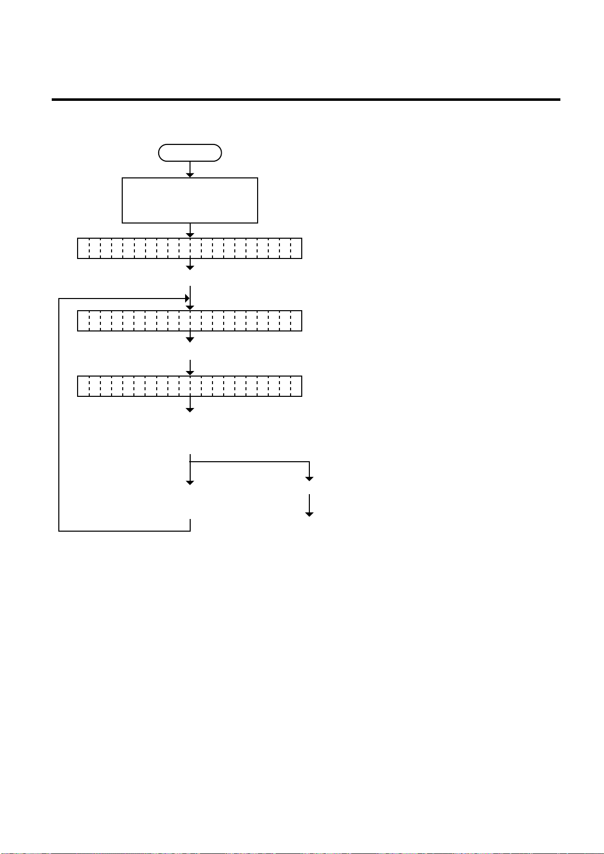
6. DIAG. TEST OPERATION
6.3.9 Ribbon Type Selection
Power off
Turn on the power while
holding down the [FEED]
key and [PAUSE] key.
<1 DIAGNOSTI C V1.OA>
Press the [FEED] key.
<2 PARAMETER SET>
Press the [PAUSE] key ten times.
(Revision Date Jun. 28, ’96)
EM18-33013
6.3 PARAMETER SETTING MODE
RI BON TRANS.B
• Transmissive ribbon
Transmissive: With ribbon
Select either ribbon type with
the [FEED] key or [RESTART]
key. (See NOTE 1and 2.)
Non-transmissive: Ribbon end
• Non-Transmissive ribbon
Transmissive: Ribbon end
Non-transmissive: With ribbon
Press the [PAUSE] key.
Press the [RESTART]
key. (See NOTE 3.)
Continued on Section 6.3.10
Ribbon Motor Drive Voltage
Fine Adjustment.
NOTES: 1. Holding the [FEED] key or [RESTART] key down for more than 0.5 seconds enables
a fast forward.
2. Non-transmissive (NON TRANS.) ribbon cannot be used so the ribbon type must be
set to transmissive (TRANS.) ribbon.
3. A change ribbon type is stored in memory by pressing the [PAUSE] key.
6-29
Page 59
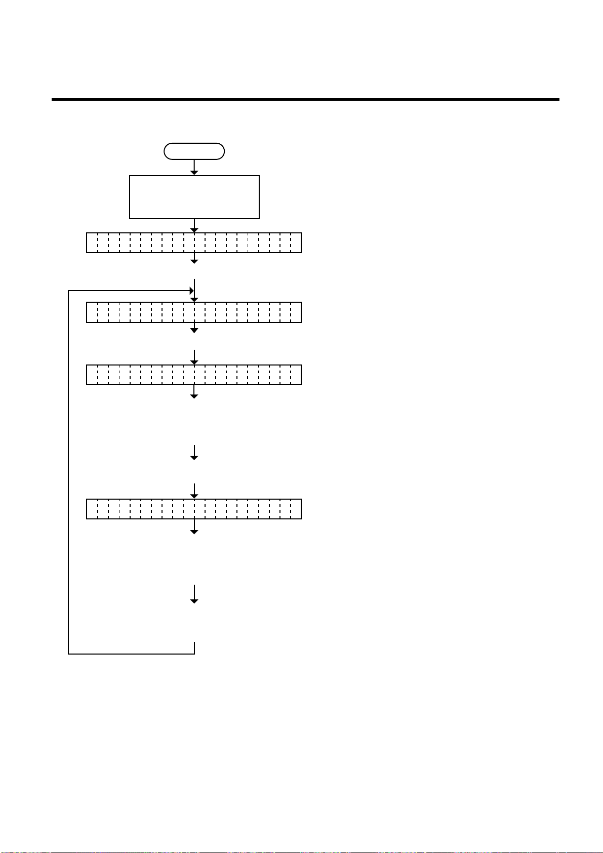
6. DIAG. TEST OPERATION
6.3.10 Ribbon Motor Drive Voltage Fine Adjustment
Power off
Turn on the power while
holding down the [FEED]
key and [PAUSE] key.
<1 DIAGNOSTIC V1.OA>
Press the [FEED] key.
<2 PARAMETER S ET>
Press the [PAUSE] key eleven times.
(Revision Date Jun. 28, ’96)
EM18-33013
6.3 PARAMETER SETTING MODE
RI BON ADJ <FWD> +0B
Press the [FEED] or
[RESTART] key to fine
adjust the feed motor
voltage. (See NOTE 1.)
Press the [PAUSE] key.
(Ribbon feed motor voltage fine adjustment)
■ [FEED] key: Pressing the [FEED] key one time is a
-1 step change, up to -15 steps.
(SeeNOTE2.)
■ [RESTART]key: Pressing the [RESTART] key one time
is a -1 step change, up to -15 steps.
(See NOTE 2.)
(See NOTE 3.)
RI BON ADJ <BAK> +0B
(Ribbon rewind motor voltage fine adjustment)
Press the [FEED] or
[RESTART] key to fine
adjust the rewind motor
voltage. (See NOTE 1.)
Press the [FEED] key
and [RESTART] key
■ [FEED] key: Pressing the [FEED] key one time is a
-1 step change, up to -15 steps.
(See NOTE 2.)
■ [RESTART]key: Pressing the [RESTART] key one time
is a -1 step change, up to -15 steps.
(See NOTE 2.)
at the same time.
NOTES: 1. Holding the [FEED] key or [RESTART] key down for more than 0.5 seconds enables
a fast forward.
2. Max. fine adjustment -15 steps = Key fine adjustment value (-15 steps) + PC fine
adjustment value (-15 steps)
When the value reaches the maximum, the value remains unchanged even if the
subsequent fine adjustment is performed.
3. A changed motor voltage value is stored in memory by pressing the [PAUSE] key.
4. One step corresponds to 5% of the standard voltage and up to 75% of the voltage can
be decreased.
6-30
Page 60
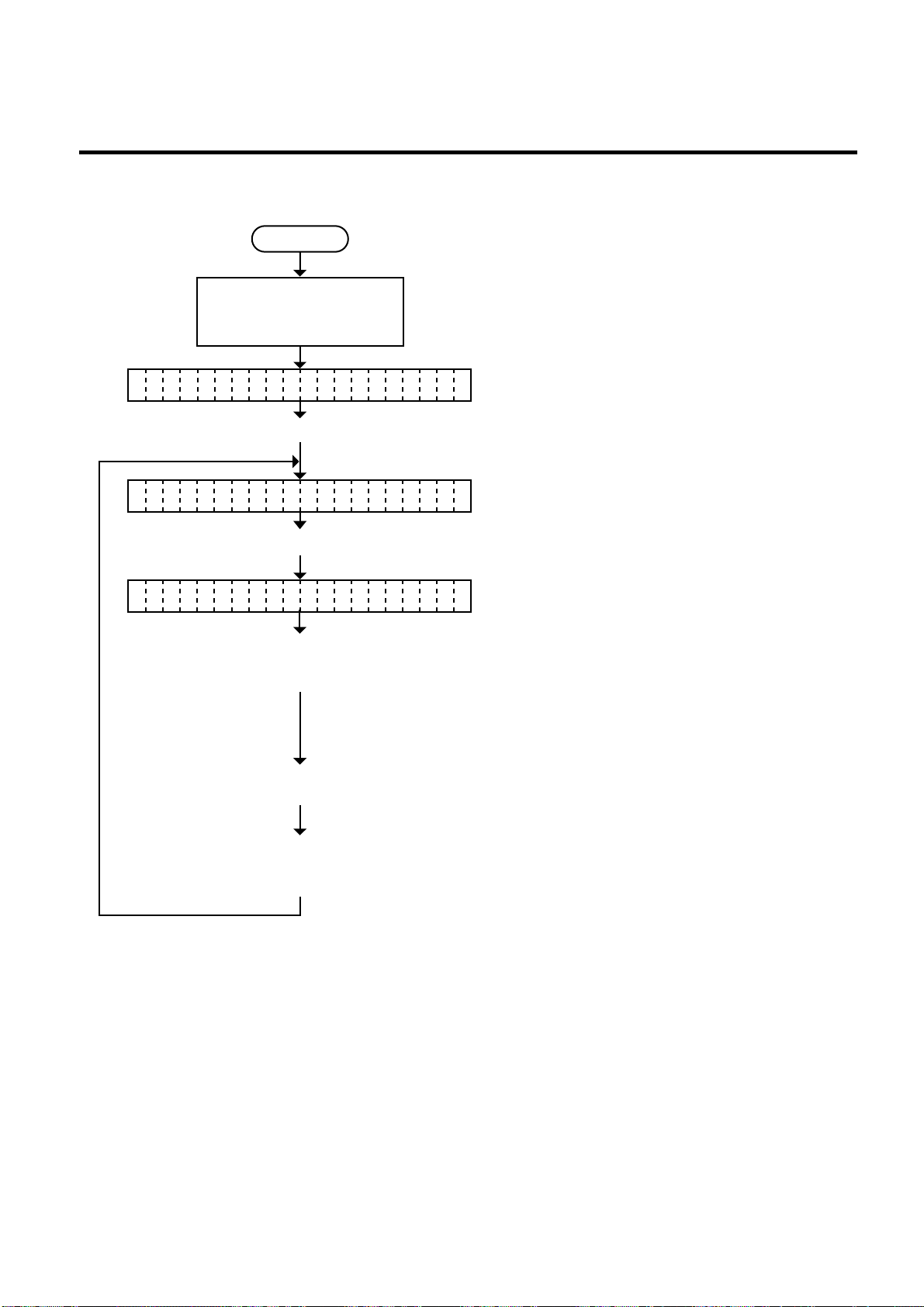
6. DIAG. TEST OPERATION
6.3.11 Strip Wait Status Setting
Power off
Turn on the power while
holding down the [FEED]
key and [PAUSE] key.
<1 DIAGNOSTI C V1.OA>
Press the [FEED] key.
<2 PARAMETER SET>
(Revision Date Dec. 10, ’96)
EM18-33013
6.3 PARAMETER SETTING MODE
Press the [PAUSE] key thirteen times.
ST TUS TYPE +0A
Press the [FEED] key or
[RESTART] key to select
■ [FEED] key
Status type 2: A strip wait status is sent.
the strip wait status.
Press the [PAUSE] key.
(See NOTE 1.)
■ [RESTART]key
Status type 1: A strip wait status is not sent.
Press the [FEED] key
and [RESTART] key
at the same time.
NOTE: When the status type 1 is selected, the printer will send (00H) in response to the status
request command sent from the PC while a label stays at the strip sensor (when idling, after
feeding, or all printing finished).
When the status type 2 is selected, the printer will send (05H) in response to the status
request command sent from the PC while a label stays at the strip sensor (when idling, after
feeding, or all printing finished.)
If the status request command is sent during printing, the printer will always send (05H)
regardless of the setting.
6-31
Page 61
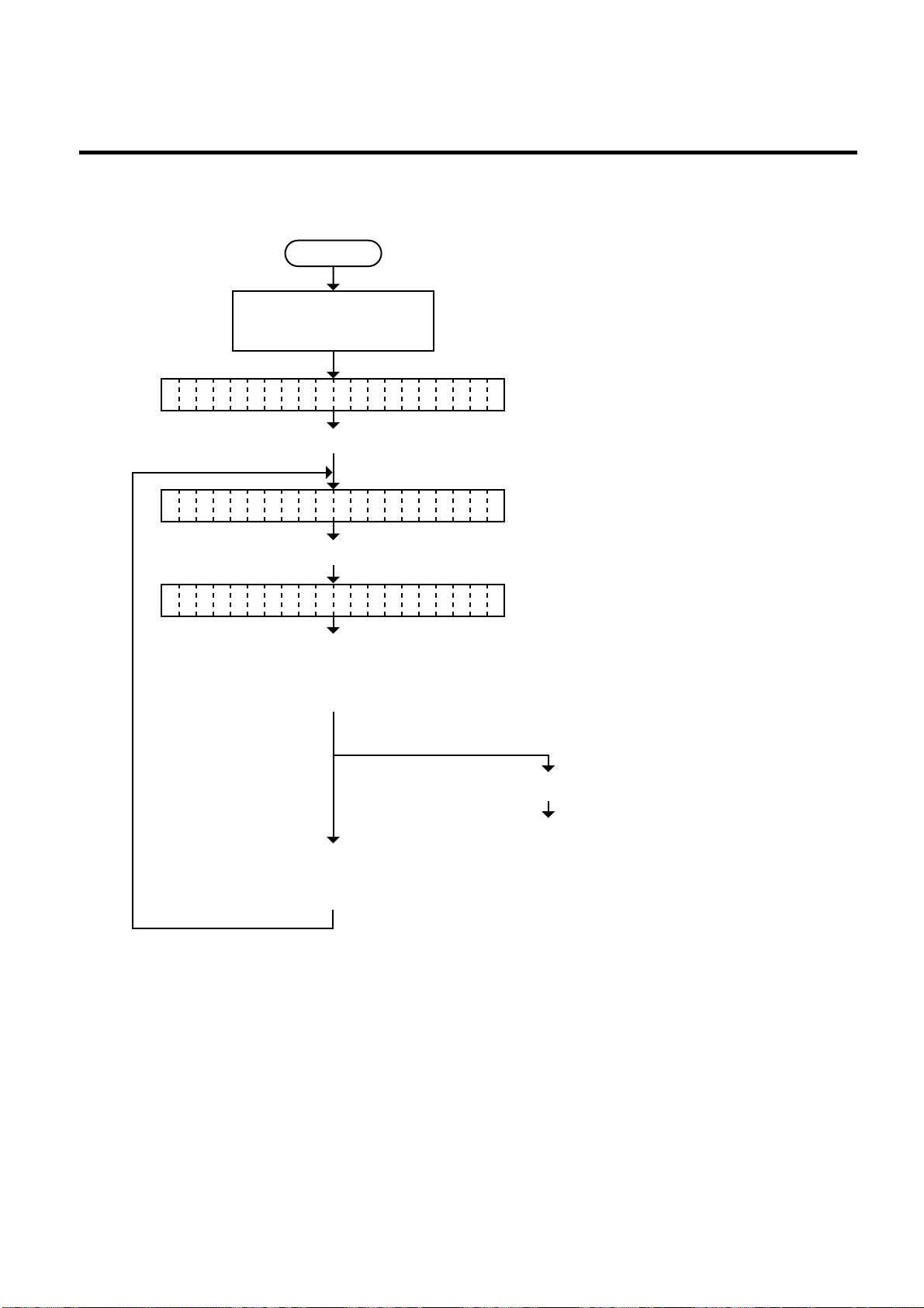
6. DIAG. TEST OPERATION
6.3.12 Threshold Manual Fine Adjustment for the Black Mark Sensor
Power off
Turn on the power while
holding down the [FEED]
key and [PAUSE] key.
<
>
1 DIAGNOSTIC V1.OA
Press the [PAUSE] key.
<
>
2 PARAMETER SET
(Revision Date: Dec. 10 ‘99)
EM18-33013
6.3 PARAMETER SETTING MODE
Press the [PAUSE] key fourteen times.
TH ESHOLD R 1.0VR
Press the [FEED] key or
[RESTART] key to fine
adjust the black mark
sensor manual threshold.
■ [FEED] key:
Pressing the [FEED] key onetime is a - 0.1V change,
up to 0.0V
■ [RESTART]key:
Pressing the [RESTART] key onetime is a
+0.1V change, up to 4.0V.
Press the [PAUSE] key.
Continued on Section
6.3.13 Threshold Manual
Press the [FEED] key
and [RESTART] key at the
Fine Adjustment for the
Feed Gap Sensor.
same time.
NOTE: 1. Holding the [FEED] key or [RESTART] key down for more than 0.5 seconds enables
a fast forward.
2. A changed threshold fine adjustment value is stored in memory by pressing the
[PAUSE] key
3. The above operations do not require any more threshold setting.
6-32
Page 62
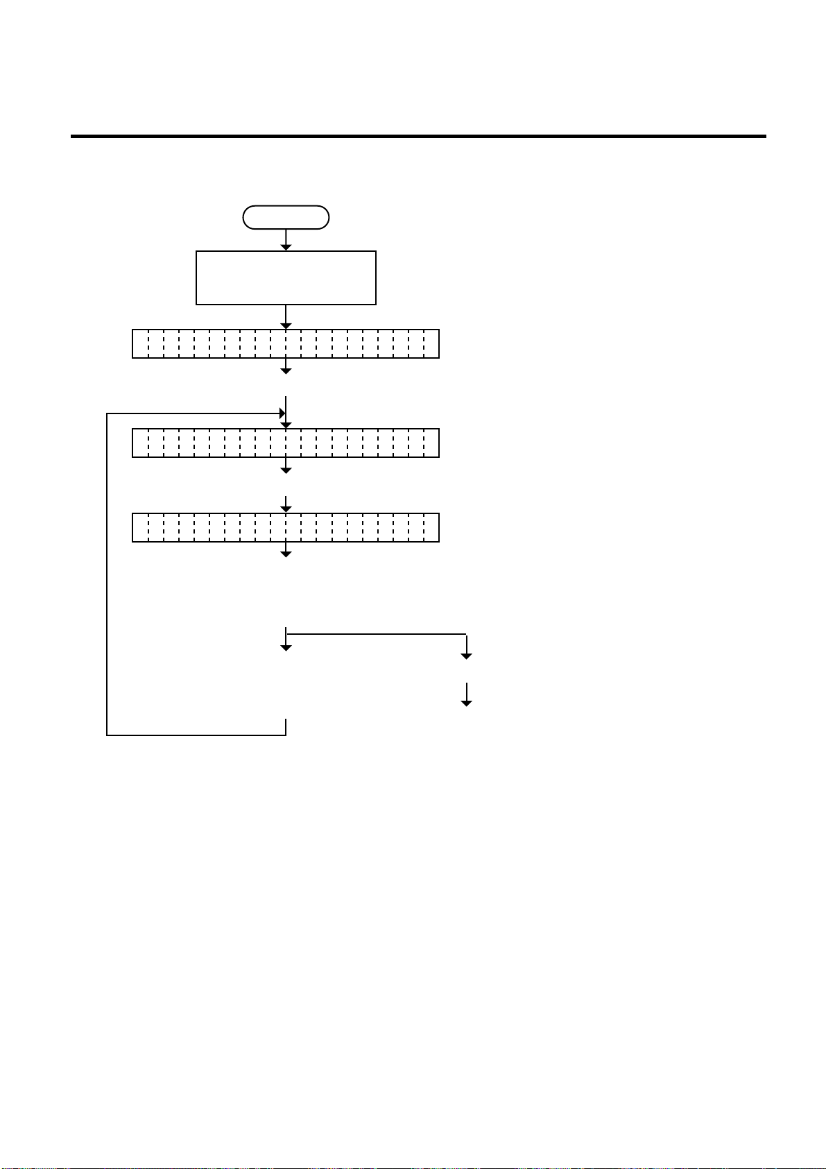
6. DIAG. TEST OPERATION
6.3.13 Threshold Manual Fine Adjustment for the Feed Gap Sensor
Power off
Turn on the power while
holding down the [FEED]
key and [PAUSE] key.
<
>
1 DIAGNOSTIC V1.OA
Press the [PAUSE] key.
<
>
2 PARAMETER SET
(Revision Date: Dec. 10 ‘99)
EM18-33013
6.3 PARAMETER SETTING MODE
Press the [PAUSE] key fifteen times.
TH ESHOLD T 1.4VR
Press the [FEED] key or
[RESTART] key to fine
adjust the feed gap sensor
manual threshold.
Press the [FEED] key
■ [FEED] key:
Pressing the [FEED] key onetime is a - 0.1V
change, up to 0.0V
■ [RESTART]key:
Pressing the [RESTART] key onetime is a
+0.1V change, up to 4.0V.
Press the [PAUSE] key.
and [RESTART] key at the
same time.
Continued on Section
6.3.14 Kanji Code
Selection.
NOTES: 1. Holding the [FEED] key or [RESTART] key down for more than 0.5 seconds enables
a fast forward.
2. A changed threshold fine adjustment value is stored in memory by pressing the
[PAUSE] key.
3. The above operations do not require any more threshold setting.
6-33
Page 63

6. DIAG. TEST OPERATION
(Revision Date: Jan. 14 ‘99)
6.3 PARAMETER SETTING MODE
EM18-33013
■ How To Calculate Theshold Fine Adjustment Value
If the following cases occurred, threshold value for the paper sensors should be fine adjusted after
referring to the next page.
Case 1:
When using tag paper, the black mark and the print area are distinguished from each other by the 1.5V
or more difference of sensor output voltage.
not detect 1.5V or more difference between the black mark and the print area. This may cause the
printer to feed over one and a half tags, and then stop with “PAPER JAM” displayed.
Case 2:
The presence and lack of label are distinguished from each other by the reflective sensor voltage.
When the voltage is more than 1.5V, it is regarded as the presence of paper. And less than 1.5V is
regarded as the paper end. If a low-sensitive-sensor is used, 1.5V or more may not be detected at
the backing paper since the reflectance of backing paper is low. In such case, more than 5mm-long
gap is regarded as the no paper. And trying to print or feed the label when the sensor stops at the
gap results in a NO PAPER error.
This problem tends to occur when using labels with thin backing
paper.
If a low-sensitive sensor is installed in the printer, it may
Case 3:
If the reflective sensor’s output voltage when detecting no paper is 1.5V or more, the sensor does not
recognize the actual paper end during printing. Accordingly, the printer continues to print despite of
the paper end. This problem may occur on printers of which the resistors on the CPU PCB have been
changed according to the Technical Information #SVM7A1010/1 (issued on April 16, 1997).
Case 4:
When using perforated fanfold labels, the transmissive sensor mistakes the perforation on the gap for
a print area, resulting in a PAPER JAM error.
Case 5:
When using such a particular label stock that a black mark is printed on every two or three gaps, the
sensor detects three different voltages at the label, unmarked gap and black mark, respectively. The
sensor cannot distinguish the unmarked gap from the black mark, so the printer stops with displaying
“PAPER JAM”.
6-34
Page 64
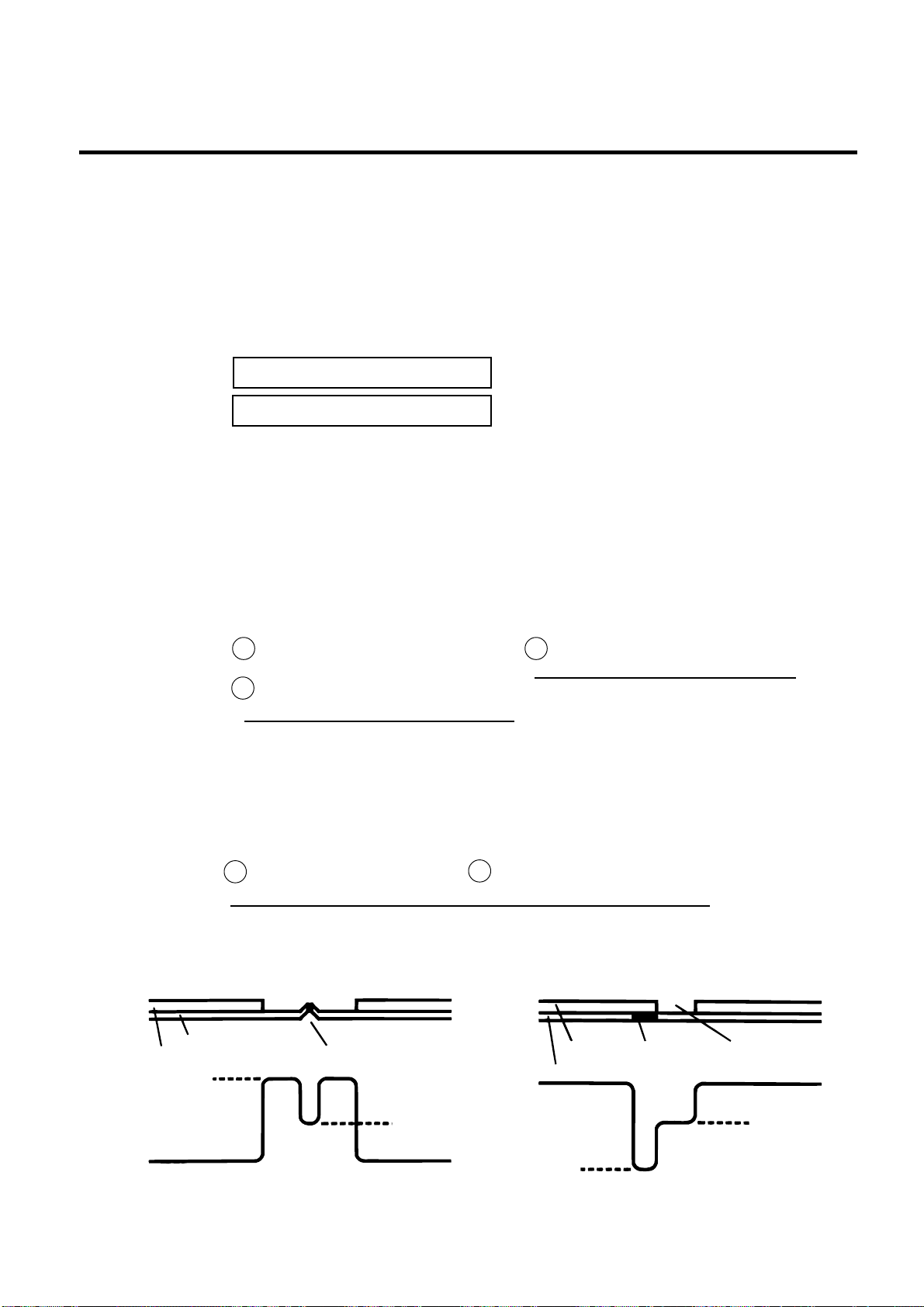
6. DIAG. TEST OPERATION
(Revision Date: Jan. 14 ‘99)
6.3 PARAMETER SETTING MODE
EM18-33013
NOTE: The following operation cannot be performed unless the sensor type is changed by the issue
command or feed command.
(1) Using the sensor adjustment in Diag. mode, measure the sensor voltage at the following four points.
Label: Print area Backing paper
Tag paper: Print area Black mark
Example:
[ R E F L E C T I V E ] 2 . 8 V
[ T R A N S M I S S I V E ] 4 . 1 V
(2) Using the following formula, calculate the threshold from the measured voltage:
When using labels (transmissive sensor):
Threshold = (Max. voltage at the backing paper) - (Voltage at the print area) - 0.7V
e.g.) 2.0V = 4.2V - 1.5V - 0.7V
When using perforated labels (transmissive sensor):
A
Threshold = (Max. voltage at the backing paper) Min. voltage at the backing paper
A
B
-
2
Max. voltage at the backing paper
2
e.g.) 2.2V = 4.4V - (2.8V/2) - (1.6V/2)
When using labels with black marks (reflective sensor):
C
D
Threshold = (Min. voltage at the print area) - (Min. voltage at the black mark)
2
e.g.) 0.4V = (1.5V - 0.7V)/2
-
Backing Paper
Label
A
(4.4 V)
Perforation
(2.8 V)
B
6-35
Label
Backing Paper
(0.7 V)
Black Mark Label gap
D
C
(1.5 V)
Page 65
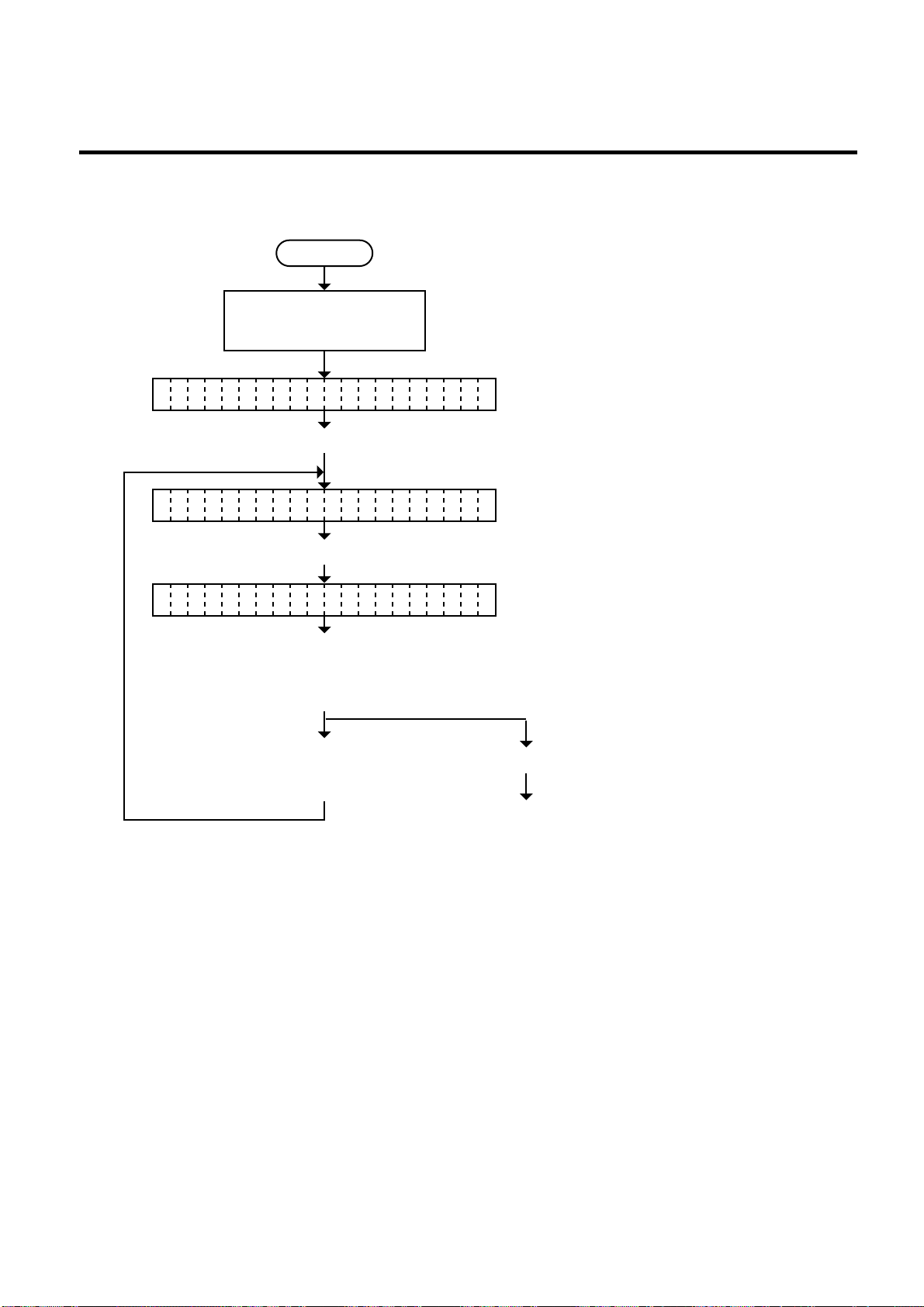
6. DIAG. TEST OPERATION
6.3.14 Kanji Code Selection
Power off
Turn on the power while
holding down the [FEED]
key and [PAUSE] key.
<
>
1 DIAGNOSTIC V1.OA
Press the [PAUSE] key.
<
>
2 PARAMETER SET
(Revision Date: Jul. 26 ‘99)
EM18-33013
6.3 PARAMETER SETTING MODE
Press the [PAUSE] key 16 times.
KA JI CODE YPE1N
Select either code with the
T
■ Windows code
■ Original code
[FEED] key or [RESTART]
key.
Press the [FEED] key and
[RESTART] key at the
Press the [PAUSE] key.
same time.
Continued on Section
6.3.15 Euro Font Code
Selection.
NOTES: 1. Holding the [FEED] key or [RESTART] key down for more than 0.5 seconds enables
a fast forward.
2. A changed Kanji code is stored in memory by pressing the [PAUSE] key.
6-36
Page 66
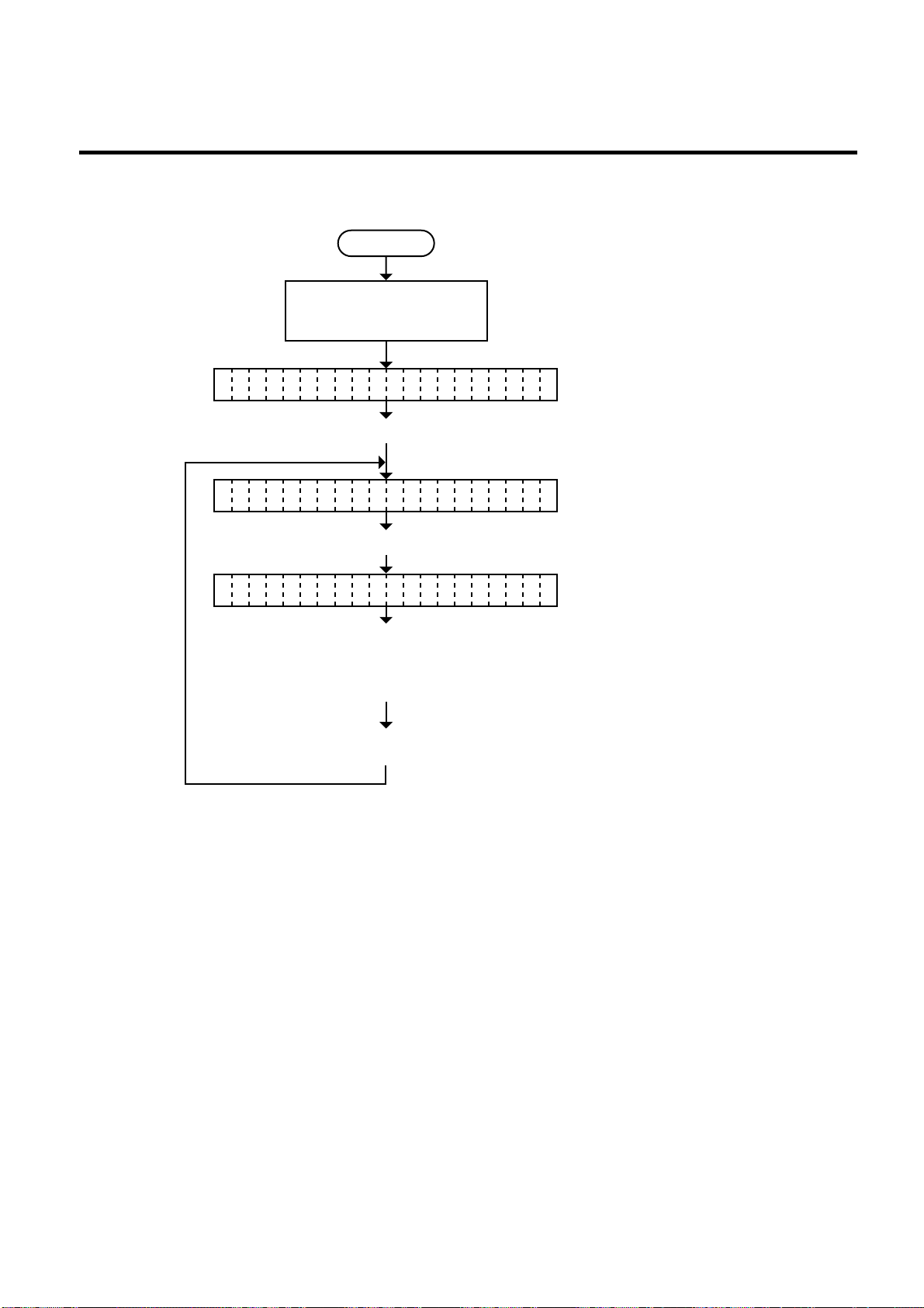
6. DIAG. TEST OPERATION
6.3.15 Euro Font Code Selection
Turn on the power while
holding down the [FEED]
key and [PAUSE] key.
<
>
1 DIAGNOSTIC V1.OA
Press the [PAUSE] key.
<
>
2 PARAMETER SET
(Revision Date: Jul. 26 ‘99)
EM18-33013
6.3 PARAMETER SETTING MODE
Power off
Press the [PAUSE] key 17 times.
EU O CODE BOHR
Select the Euro font code
with the [FEED] key on
[RESTART] key.
•20H
[RESTART] key ↑↓ [FEED] key
•FFH
Press the [PAUSE] key.
NOTES: 1. Holding the [FEED] key or [RESTART] key down for more than 0.5 seconds enables
a fast forward.
2. A changed Euro font code is stored in memory by pressing the [PAUSE] key.
6-37
Page 67
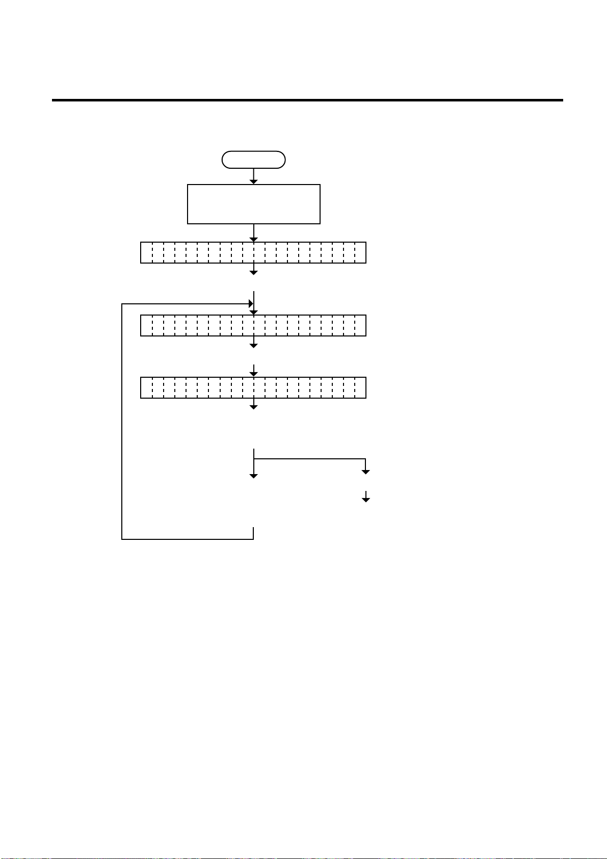
6. DIAG. TEST OPERATION
6.3.16 Head Type Selection
<
>
1 DIAGNOSTIC V1.OA
<
>
2 PARAMETER SET
(Revision Date: Dec. 10 ‘99)
EM18-33013
6.3 PARAMETER SETTING MODE
Power off
Turn on the power while
holding down the [FEED]
key and [PAUSE] key.
Press the [PAUSE] key.
Press the [PAUSE] key 18 times.
HE D YPE1A
Select the Head Type with
the [FEED] key on
T
•TYPE 1: KCE-213-12MPT2-TEB
•TYPE 2: KCE-213-12MPT2-TEA
[RESTART] key.
Press the [PAUSE] key .
Press the [FEED] key and
[RESTART] key at the s
ame time.
Continued on Section
6.3.17 Transmission
Control Mode Selection.
NOTES: 1. Holding the [FEED] key or [RESTART] key down for more than 0.5 seconds enables
a fast forward.
2. A changed Head type is stored in memory by pressing the [PAUSE] key.
6-38
Page 68
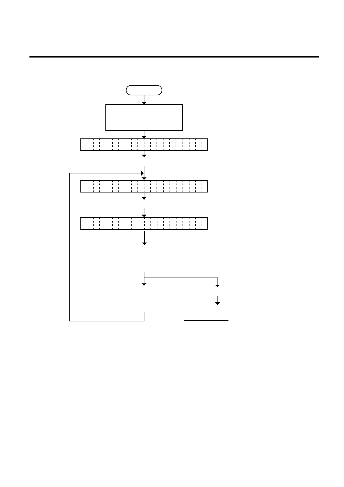
6. DIAG. TEST OPERATION
Power off
Turn on the power while
holding down the [FEED]
key and [PAUSE] key.
Press the [FEED] key.
Press the [PAUSE] key 19 times.
Select the Transmission Control
Mode with the [FEED] key
or [RESTART] key.
Press the [FEED] key and
[RESTART] key at the
same time.
• DTR: READY/BUSY (DTR) protocol
(DTR/DSR)
• RTS: READY/BUSY (RTS) protocol
(RTS/CTS)
<1 DI AGN I C. V>
1. OA
OS T
<2 PARAM R SET>
ETE
DT /RTS R
DTR
Press the [PAUSE] key.
Continued on Section 6.3.18
Reset Selection when the
INPUT • PRIME Signal is ON.
6.3.17 Transmission Control Mode Selection
(Revision Date: Dec. 10 ‘99)
EM18-33013
6.3 PARAMETER SETTING MODE
NOTES: 1. Holding the [FEED] key or [RESTART] key down for more than 0.5 seconds enable.
2. A changed Transmission Control Mode is memory by pressing the [PAUSE] key.
6-39
Page 69

6. DIAG. TEST OPERATION
6.3.18 Reset Selection when the INPUT • PRIME Signal is ON.
Reset ON/OFF when the INPUT • PRIME signal ON is selected.
Power off
Turn on the power while
holding down the [FEED]
key and [PAUSE] key.
(Revision Date: Dec. 10 ‘99)
EM18-33013
6.3 PARAMETER SETTING MODE
<1 DIAGN IC. V>
OST
Press the [FEED] key.
<2 PARAM R SET>
ETE
Press the [PAUSE] key 20 times.
IN UT PR P
IME
Select the "Reset ON/OFF
when the INPUT • PRIME
signal is ON" with the [FEED] key
or [RESTART] key.
Press the [PAUSE] key.
1.OA
ON
• ON: The printer will restore to the initial status.
• OFF: The printer will not restore to the initial status.
NOTES: 1. Holding the [FEED] key or [RESTART] key down for more than 0.5 seconds enable.
2. A changed “Reset ON/OFF when the INPUT • PRIME signal is ON” is stored in memory by
pressing the [PAUSE] key.
6-40
Page 70
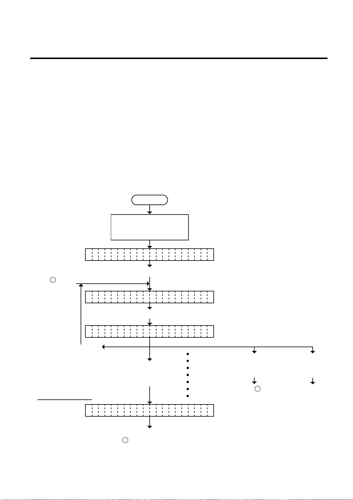
6. DIAG. TEST OPERATION
6.4 TEST PRINT MODE
6.4 TEST PRINT MODE
Test print mode contains normal test print and process test print.
6.4.1 Normal Test Print
Five kinds of test prints are provided in the test print mode. When performing the test print, 7
parameters should be set. The default parameter at power on is as below:
• ISSUE COUNT : 1
• PRINT SPEED : 4 inch/sec.
• SENSOR : Transmissive sensor (Feed Gap Sensor)
• RIBBON : Transmissive ribbon
• TYPE : Batch (without cut)
• LABEL LENGTH : 76 mm
• PAPER FEED : Feed
Operating procedure for the test mode is provided below.
Power off
EM18-33013
<1 DIAGNOSTIC V1.OA>
From C on
the next page.
<3 TEST PRINT>
PR NT CONDITIONI
Press the [FEED] key
and [RESTART] key at
the same time.
Set the print count
IS UE COUNT 1S
Turn on the power while
holding down the [FEED]
key and [PAUSE] key.
Press the [FEED] key twice.
Press the [PAUSE] key.
Select "Print Condition"
by pressing the
[PAUSE] key.
ISSUE COUNT
PRINT SPEED
SENSOR
RIBBON
TYPE
LABEL LENGTH
PAPER FEED
Press the [FEED] key
or [RESTART] key.
(See NOTE 1.)
To
A
Press the
[RESTART]
key.
Continued on
Section 6.4.2
Process Test
Print.
To be continued on
B
of the next page.
6-41
Page 71
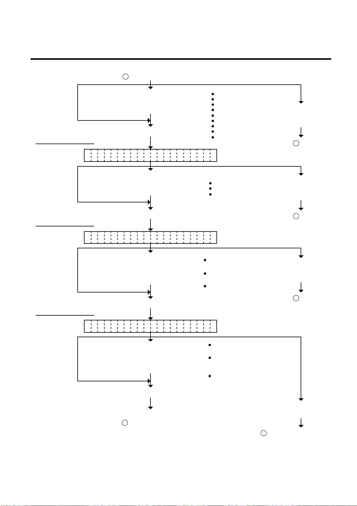
6. DIAG. TEST OPERATION
PR NT SPEED 4inch/sI
SE SOR TRANSMISSIVEN
RI BON TRANSMISSIVEB
5000 (Print count 5000)
Set the print count from those at the
right by pressing the [FEED] key or
[RESTART] key. (See NOTE 2.)
Select the print speed from those at
the right by pressing the [FEED]
key or [RESTART] key.
Select the sensor type from
those at the right by pressing
the [FEED] key or [RESTART]
key. (See NOTE 2 and 4.)
Select the ribbon type from
those at the right by pressing
the [FEED] key or [RESTART]
key. (See NOTE 2, 5 and 9.)
Press the [FEED] key
and [RESTART] key
at the same time.
Press the [FEED] key
and [RESTART] key
at the same time.
Press the [PAUSE] key. (See NOTE 3.)
Press the [PAUSE] key. (See NOTE 3.)
Press the [PAUSE] key. (See NOTE 3.)
Press the [PAUSE] key. (See NOTE 3.)
1000 (Print count 1000)
500 (Print count 500)
100 (Print count 100)
50 (Print count 50)
10 (Print count 10)
5 (Print count 5)
3 (Print count 3)
1 (Print count 1)
3 inch/sec.
NONE
(consecutive form)
NO RIBBON
(No ribbon: Thermal direct)
NO TRANS.
(Non-transmissive ribbon:
Thermal transfer)
TRANSMISSIVE
(Transmissive ribbon:
Thermal transfer)
REFLECTIVE
(black mark sensor)
TRANSMISSIVE
(feed gap sensor)
4 inch/sec.
8 inch/sec.
Set the print speed
Set the sensor type
Set the ribbon type
To C of the
preceding page.
To C of the
preceding page.
Press the [FEED] key
and [RESTART] key
at the same time.
Press the [FEED] key and
[RESTART] key at the same
time.
To C of the
preceding page.
To C of the preceding page.
To be continued on
B of the next page.
From B of the preceding page.
EM18-33013
6.4 TEST PRINT MODE
6-42
Page 72

6. DIAG. TEST OPERATION
From
Set the issue mode type
TY E [S] NO CUTTINGP
B
of the preceding page.
EM18-33013
6.4 TEST PRINT MODE
Set the label length
LA EL LENGTH 76mmB
Set the media feed
PA ER FEEDP
Select the issue mode type from
those at the right by pressing
the [FEED] key or [RESTART]
key. (See NOTE 2.)
Press [PAUSE] key. (See NOTE 3.)
Select the label length from
those at the right by pressing
the [FEED] key or [RESTART]
key. (See NOTE 6 AND 7.)
Press the [PAUSE] key. (See NOTE 3.)
[S] Standard mode
(Batch printing without cut)
[C] Auto-cut mode
(Issue and cutting)
[H] Strip mode
(On-demand printing
without cut)
999 (Label length 999 mm)
998 (Label length 998 mm)
997 (Label length 997 mm)
~
7 (Label length 7 mm)
6 (Label length 6 mm)
5 (Label length 5 mm)
Press the [FEED] key
and [RESTART] key
at the same time.
To
C
of the
preceding page.
Press the [FEED] key
and [RESTART] key
at the same time.
To
C
of the
preceding page.
Select the media feed from those
at the right by pressing the
PAPER FEED
PAPER NO FEED
[FEED] key or [RESTART] key.
(See NOTE 2.)
Press the [PAUSE] key. (See NOTE 3.)
Press the [PAUSE] key. (Feed one media.)
To be continued on
B
of the next page.
6-43
Press the [FEED] key
and [RESTART] key
at the same time.
To C of the
preceding page.
Page 73

6. DIAG. TEST OPERATION
<3 TEST PRINT>
PR NT CONDITIONI
From A of the
preceding page.
B of the preceding page.
From
Press the [PAUSE] key.
EM18-33013
6.4 TEST PRINT MODE
<3 TEST PRINT>
Select the test print from
those at the right by
pressing the [FEED] key
or [RESTART] key.
A designated number of
test prints are issued when
pressing the [PAUSE] key.
(See NOTE 8.)
Press the [PAUSE] key.
SLANT LINE (1 DOT)
SLANT LINE (3 DOT)
CHARACTERS
BAR CODE
NON-PRINTING
AUTO PRINT (TRANS.) :
Process test print/Transmissive sensor
AUTO PRINT (REFLECT.) :
Process test print/Reflective sensor
Press the [FEED] key
and [RESTART] key at
the same time.
NOTES: 1. When there is no change to the print condition, select one of the test print options to
issue the test print.
2. Holding the [FEED] key or [RESTART] key down for more than 0.5 seconds enables
a fast forward.
3. A selected print condition is activated when the [PAUSE] key is pressed.
4. When the feed gap sensor is selected, the gap between labels becomes 3mm long.
5. Non-transmissive (NON TRANS.) ribbon cannot be used so the ribbon type must be
set to transmissive (TRANS.) ribbon or no ribbon.
6-44
Page 74

6. DIAG. TEST OPERATION
6. A label size greater than the image buffer length cannot be designated. The image
buffer length differs according to memory size. If designated, the printer prints in
the image buffer, or the printer stops because of an error.
7. Pressing the [FEED] key changes the label length -1 mm, pressing the [RESTART]
key changes +1 mm.
8. When an error occurs during a test print, the error message is displayed and printing
is stopped. The error is cleared by pressing the [PAUSE] key and the display shows
“<3> TEST PRINT”. Printing is not automatically resumed after the error is cleared.
9. When the transmissive ribbon is selected and DIP SW. 1-1 is set to ON, and the
space area is also 20 mm or more when the print speed is 3"/sec. or 4"/sec. or 25
mm or more when 8"/sec, the printer automatically enters ribbon saving print mode.
10. When ‘AUTO PRINT’ is selected, 5 pcs. of the 3-dots slant line labels, bar code
labels and character labels are printed respectively after one label is fed.
■ Test Print Sample
• Slant line (1 dot)
EM18-33013
6.4 TEST PRINT MODE
• Slant line (3 dot)
Fig. 6-21
Fig. 6-22
6-45
Page 75
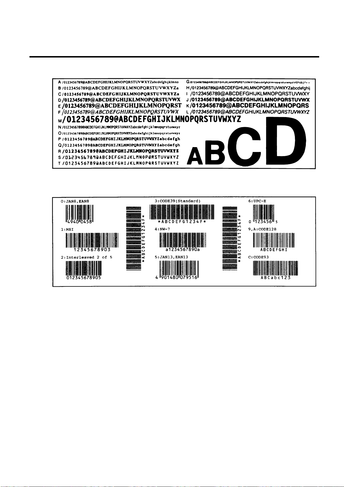
6. DIAG. TEST OPERATION
• Characters
• Bar code
EM18-33013
6.4 TEST PRINT MODE
Fig. 6-23
6-46
Fig. 6-24
Page 76

6. DIAG. TEST OPERATION
6.4 TEST PRINT MODE
6.4.2 Process Test Print
In the precess test print, the test print is automatically performed under the following conditions.
Parameter setting and print tone fine adjustment value is ignored.
• OPERATION : One label feed, 3-dot slant line print, bar code print, character print
• ISSUE COUNT : 5 labels each
• PRINT SPEED : 4 inches/sec.
• SENSOR : Transmissive sensor (feed gap sensor) or reflective sensor (black mark
sensor)
• RIBBON : Transmissive ribbon
• TYPE : Batch (without cut)
• LABEL LENGTH: 76 mm
• PRINT TONE FINE ADJUSTMENT VALUE : + 0
Operating procedure for the test mode is provided below.
Power off
EM18-33013
From C on
the next page.
Press the [RESTART]
key.
To A of the
preceding page.
Turn on the power while
holding down the [FEED]
key and [PAUSE] key.
<1 DIAGNOSTI C V1.OA>
Press the [FEED] key twice.
<3 TEST PRINT>
Press the [PAUSE] key.
PR NT CONDITIONI
Press the [RESTART] key.
After feeding one label, slant
lines (3 dots) are printed on 5
labels.
AU O PRINT(REFLECT.)T
Press the [PAUSE] key.
[Bar codes are printed on 5 labels.]
To be continued on
B of the next page.
6-47
Press the [FEED] key
and [RESTART] key
at the same time.
To C of the
preceding page.
Page 77
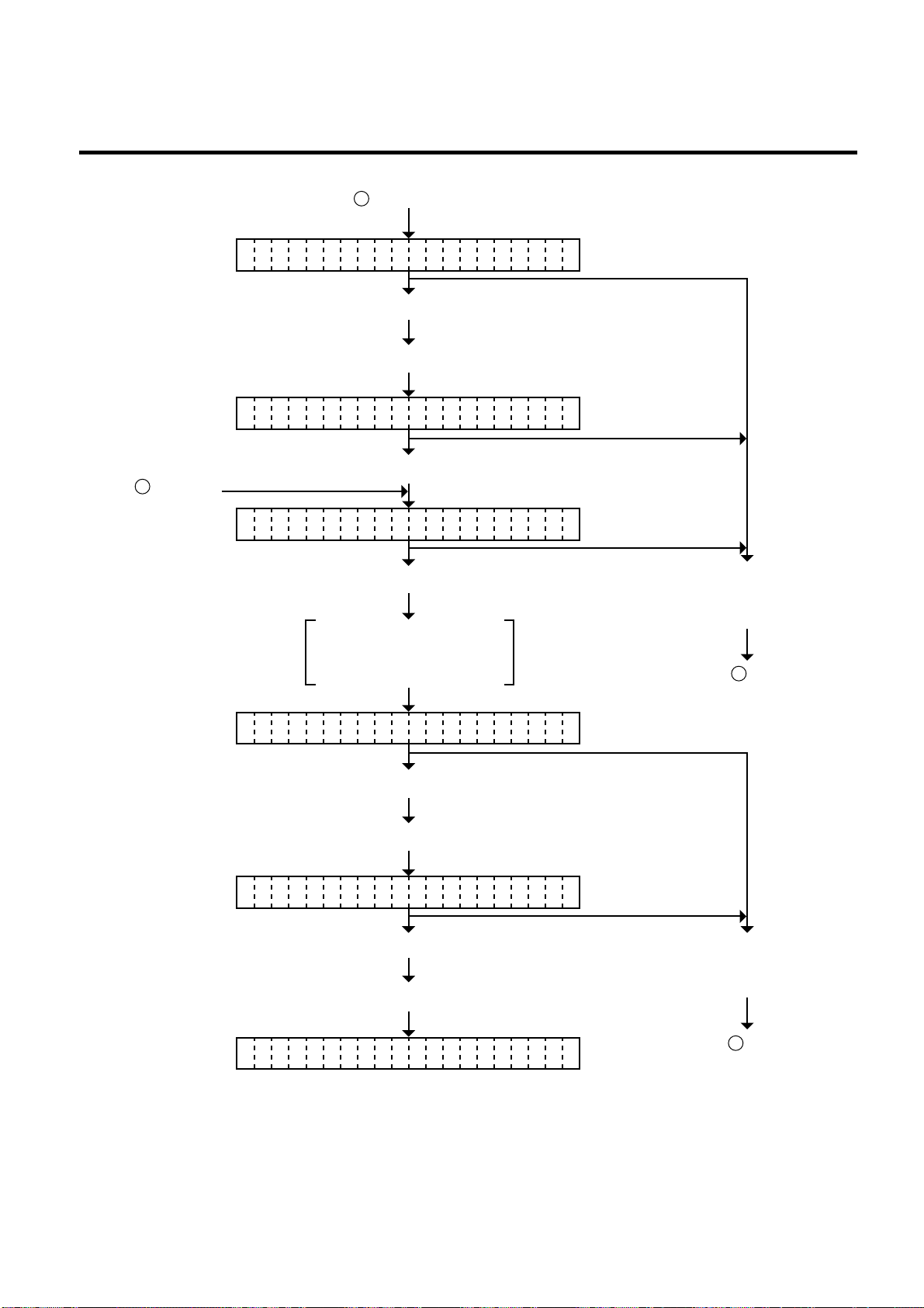
6. DIAG. TEST OPERATION
AU O PRINT(REFLECT.)T
[Characters are printed on 5 labels.]
<3 TEST PRINT>
From A of the
preceding page.
AU O PRINT(TRANS.)T
B of the next page.
From
Press the [PAUSE] key.
Press the [PAUSE] key.
EM18-33013
6.4 TEST PRINT MODE
Press the [PAUSE] key.
After feeding one label,
slant lines (3 dots) are
printed on 5 labels.
AU O PRINT(TRANS.)T
Press the [PAUSE] key.
[Bar code are printed on 5 labels.]
AU O PRINT(TRANS.)T
Press the [PAUSE] key.
[Characters are printed on 5 labels.]
Press the [FEED] key.
and [RESTART] key at
the same time.
To C of the
preceding page.
Press the [FEED] key
and [RESTART] key at
the same time.
<3 TEST PRINT>
To C of the
preceding page.
6-48
Page 78

6. DIAG. TEST OPERATION
6.5 SENSOR SETTING MODE
EM18-33013
6.5 SENSOR SETTING MODE
Thermistor check and black mark/feed gap sensor setting are provided in the sensor setting mode.
The value set in this mode is printed as data of sensor 2 in Automatic diagnosis printing in self test mode.
6.5.1 Thermistor Check
Thermistor check should be performed to check the environmental temperature and print head
temperature after the excess head temp. error occurs or batch printing is performed for a long time.
Power off
Turn on the power while
holding down the [FEED]
key and [PAUSE] key.
<1 DIAGNOSTI C V1.OA>
Press the [FEED] key twice.
<4 SENSOR ASJUSTMENT>
Press the [PAUSE] key.
[H AD]2.5V [AIR]2.0VE
Press the [FEED] key
and [RESTART] key
at the same time.
[HEAD] 2.5 V
Thermistor status
(0.0 ~ 5.0 v)
Print head
[AIR]
2.0 V
Thermistor status
(0.0 ~ 5.0 v)
Environmental
temperature
NOTE: Since the thermistaor is supervised every 200 ms while displaying the status, the display
could vary.
6-49
Page 79

6. DIAG. TEST OPERATION
(Revision Date Nov. 15, ’95)
6.5 SENSOR SETTING MODE
6.5.2 Black Mark Sensor Adjustment
Black mark sensor setting should be performed after replacing the CPU PC board or changing the
tag paper to another maker’s, or when a paper feed error occurs. The black mark sensor has a
movable and a fixed mode. These are selected by the DIP switch.
After changing the black mark sensor type, follow the procedure below to make an adjustment.
Power off
Turn on the power while holding down
the [FEED] key and [PAUSE] key.
<1 DIAGNOSTIC V1.OA>
Press the [FEED] key three times.
<4 SENSOR ADJUSTMENT>
EM18-33013
Press the [FEED] key
and [RESTART] key at
the same time.
[R FLECTIVE] 2.8VE
Ex)
[R FLECTIVE] 3.8V*E
NOTES: 1. Make sure to adjust the black mark sensor using the white part of the tag paper as
2. Pressing the [PAUSE] key validates the sensor adjustment. The value of the sensor
3. When the difference is less than 1.5 V, used media may be improper (unspecified),
Press the [PAUSE] key twice.
The former value is displayed.
Black Mark
Tag paper
Set the tag paper so that the black mark
sensor can detect the white part of the
tag paper. (See NOTE 1.)
Holding the [FEED] key or [RESTART]
key down until an asterisk ( * ) is
displayed. (More than 3 seconds.)
White part
Black Mark Sensor
Align the white part of the TOSHIBA TEC
specified tag paper with the black
Black Mark
mark sensor.
(See NOTE 2.)
Indicates adjustment complete.
Verify that the voltage difference
between a black mark and a white part
is more than 1.5 V. (See NOTE 3)
Press the [PAUSE] key for Feed Gap Sensor Adjustment.
a criterion. Though an adjustment can be performed with the black mark, it may
cause a paper jam error.
is displayed up to 5.0 V.
or sensitivity may be dull due to an excessively old or dirty sensor. In this case change
the media to one specified, or replace or clean the sensor. Then re-adjust the black
mark sensor.
6-50
Page 80
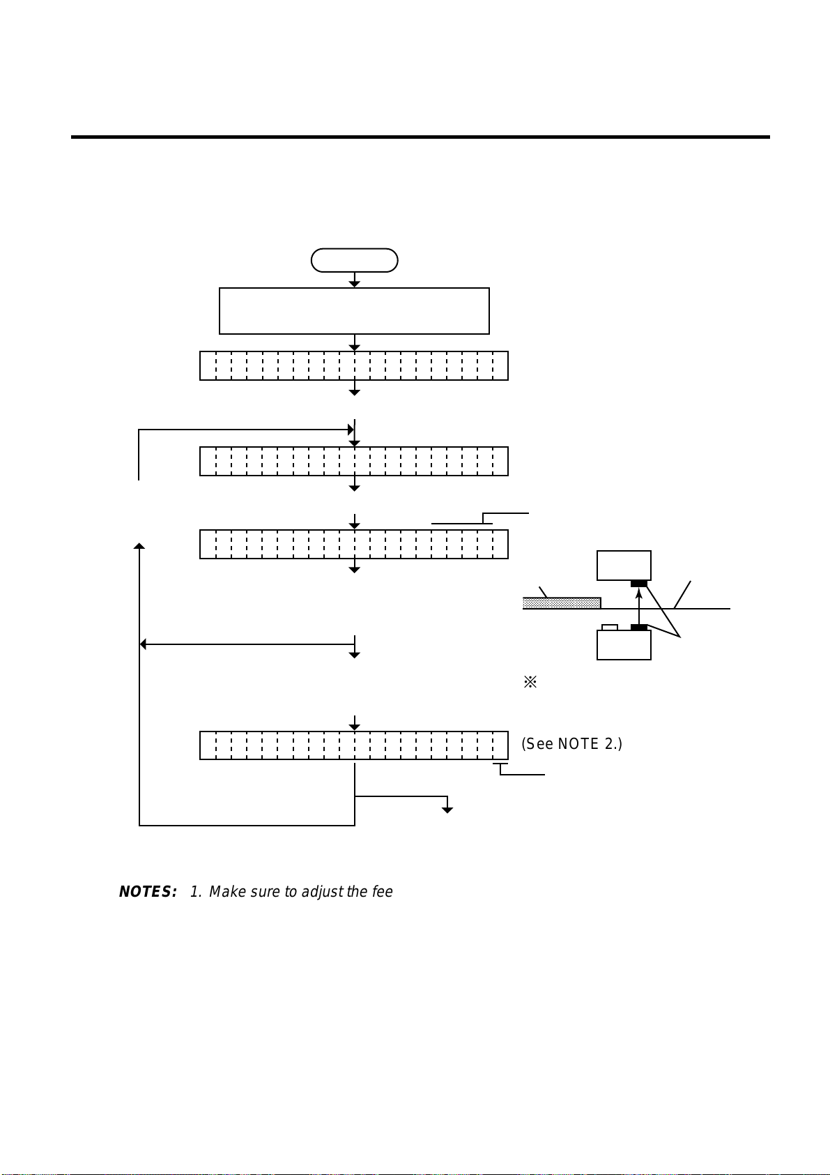
6. DIAG. TEST OPERATION
,
(Revision Date: Jan. 14 ’99)
6.5 SENSOR SETTING MODE
6.5.3 Feed Gap Sensor Adjustment
Feed gap sensor setting should be performed after replacing the CPU PC board or changing the
label to another maker’s, or when a paper feed error occurs.
Power off
Turn on the power while holding down
the [FEED] key and [PAUSE] key.
<1 DIAGNOSTI C V1.OA>
Press the [FEED] key three times.
<4 SENSOR ADJUSTMENT>
EM18-33013
Press the [FEED] key
and [RESTART] key
at the same time.
[T ANSMISSIV E] 2.3VR
Ex)
[T ANSMISSIVE] 4.1V*R
NOTES: 1. Make sure to adjust the feed gap sensor using the backing paper with no label as a
2. Pressing the [PAUSE] key validates the sensor adjustment. The value of the sensor
3. When the difference is less than 1.5 V, used media may be improper (unspecified), or
Press the [PAUSE] key three times.
The former value is displayed.
Backing
Label
Paper
Set the label so that the feed gap
sensor can detect the backing
,,,,,,,,,,,,,,
paper (no label). (See NOTE 1.)
Feed Gap Sensor
Holding the [FEED] key or [RESTART]
key down until an asterisk ( * ) is
displayed. (More than 3 seconds.)
Align the backing paper of the TEC
specified label with the feed gap
sensor.
(See NOTE 2.)
Indicates adjustment complete.
Press the [PAUSE] key for
Paper End Setting for
Black Mark Sensor.
criterion. Though an adjustment can be performed with the label, it could cause a
paper jam error.
is displayed up to 5.0 V.
sensitivity may be dull due to an excessively old or dirty sensor. In this case change
the media to one specified, or replace or clean the sensor. Then re-adjustment the
feed gap sensor.
6-51
Page 81

6. DIAG. TEST OPERATION
Power off
Turn on the power while
holding down the [FEED]
key and [PAUSE] key.
Press the [FEED] key three times.
Remove any paper
from the sensor detecting
area.
Holding the [FEED] key or
[RESTART] key down until
an asterisk ( * ) is displayed.
(More than 3 seconds.)
Ex)
The former value is displayed.
Indicates setting complete.
Press the [PAUSE] key four times.
<
1 DIAGNOSTIC V1.OA
>
<4 SENSOR ADJUSTMEN>
[P LEVEL.R] 4.3V
T
E
[P LEVEL.R] 4.3V*E
(See NOTE.)
Press the [PAUSE] key for
Paper End Setting for
Feed Gap Sensor.
Press the [FEED] key
and [RESTART] key
at the same time.
(Revision Date: Jan. 14 ’99)
6.5 SENSOR SETTING MODE
6.5.4 Paper End Setting for Black Mark Sensor
Paper end setting should be performed after replacing the CPU PC board or changing the tag paper
to other maker’s one, or when a paper feed error occurs.
EM18-33013
NOTE: Pressing the [PAUSE] key validates the sensor setting. The value of the sensor is
displayed up to 5.0 V.
6-52
Page 82
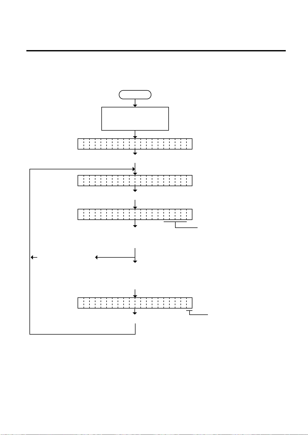
6. DIAG. TEST OPERATION
(Revision Date: Jan. 14 ’99)
6.5 SENSOR SETTING MODE
6.5.5 Paper End Setting for Feed Gap Sensor
Paper end setting should be performed after replacing the CPU PC board or changing the label
to other maker’s one, or when a paper feed error occurs.
Power off
Turn on the power while
holding down the [FEED]
key and [PAUSE] key.
<
>
1 DIAGNOSTIC V1.OA
Press the [FEED] key three times.
EM18-33013
<4 SENSOR ADJUSTMEN>
[P LEVEL.T] 4.8V
Press the [FEED] key
and [RESTART] key
at the same time.
Ex)
[P LEVEL.T] 4.8V*E
Press the [PAUSE] key. (See NOTE.)
T
Press the [PAUSE] key five times.
E
The former value is displayed.
Remove any paper
from the sensor detecting
area.
Holding the [FEED] key or
[RESTART] key down until
an asterisk ( * ) is displayed.
(More than 3 seconds.)
Indicates setting complete.
NOTE: Pressing the [PAUSE] key validates the sensor setting. The value of the sensor is
displayed up to 5.0 V.
6-53
Page 83
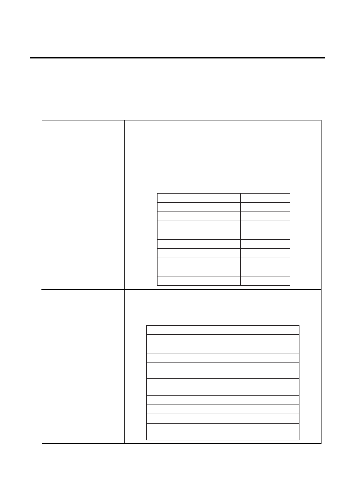
6. DIAG. TEST OPERATION
6.6 RAM CLEAR MODE
EM18-33013
6.6 RAM CLEAR MODE
In RAM clear mode, various data written on the EEP-ROM can be initialized. There are two clear
functions; Maintenance counter clear and parameter clear in the parameter setting mode. After
referring to the following table specify and clear or initialize the data.
■ RAM Clear Mode Table
Mode Name
NO RAM CLEAR
MAINTE. COUNTER
CLEAR
PARAMETER CLEAR
Function
If you enter the RAM clear mode by mistake, specify this mode to
escape from the RAM clear mode without executing RAM clear.
After replacing the print head, cutter module, ribbon feed/rewind
motor, solenoid and CPU PC Board, clear the maintenance
counter. The following data will be cleared to zero. Confirmation
can be made through the maintenance counter procedure in self
test mode. (See NOTE 1 and 2.)
metIeulaVlaitinI
derevocecnatsidaideMmK0.0
ecnatsidtnirPmK0.0
tnuoctuCsemit0
tnuocnwoddnapudaeHsemit0
emitgnivirdrotomnobbiRsruoh0
emitgnivirddioneloSsruoh0
tnuocrorreerawdrahC232-SRsemit0
tnuocrorremetsySsemit0
tnuoceruliafrewopyratnemoMsemit0
This clear should be employed when initializing the following
parameters to the setting before shipment. Confirmation can be
made through the automatic diagnostic procedure in self test
mode. (See NOTE 1 and 2.)
6-54
metIeulaVlaitinI
)CP(tnemtsujdaenifhtgneldeeFmm0.0
)CP(tnemtsujdaenifnoitisoppirts/tuCmm0.0
)CP(tnemtsujdaenifhtgneldeefkcaBmm0.0
tnemtsujdaenifenottnirP
)CP()refsnartlamrehT(
tnemtsujdaenifenottnirP
)CP()tceridlamrehT(
)YEK(tnemtsujdaenifhtgneldeeFmm0.0
)YEK(tnemtsujdaenifnoitisoppirts/tuCmm0.0
)YEK(tnemtsujdaenifhtgneldeefkcaBmm0.0
tnemtsujdaenifenottnirP
)YEK()refsnartlamrehT(
pets0
pets0
pets0
Page 84

6. DIAG. TEST OPERATION
(Revision Date: Dec. 10 ’99)
EM18-33013
6.6 RAM CLEAR MODE
Mode Name
PARAMETER CLEAR
Function
Item
Print tone fine adjustment
(Thermal direct) (KEY)
X axis fine adjustment
Character code selection
Font zero selection
Control code selection
Ribbon type selection
Ribbon motor drive voltage
fine adjustment (PC)
Ribbon motor drive voltage
fine adjustment (KEY)
Strip wait status setting
Stacker
Status response
Threshold manual fine
adjustment for the black
mark sensor
Threshold manual fine
adjustment for the feed gap
sensor
Label pitch
Effective printing length
Effective printing width
With/Without ribbon
Sensor type
Initial Value
0 step
0.0 mm
PC-850
“0”(without slash)
Auto.
Trans.
0
0
1
OFF
ON
1.0 V
1.4 V
76.2 mm
74.2 mm
128 mm
With
Transmissive sensor
(Feed gap sensor)
Feed Speed
Issue mode
5 inch/sec.
Standard
(Batch printing)
PC save automatic calling
Kanji code
Euro font code
Transmission Control Mode
Reset selection when the
ON
TYPE 1
B0H
DTR
ON
INPUT • PRIME signal is ON.
NOTES: 1. Total media distance covered (TL FEED) and the adjustment value for the sensors cannot
be cleared.
2. Data stored on the flash memory card cannot be cleared with this procedure. To clear dada
on the flash memory card, send the format command to ini tialize the card. For details, refer
to the External Equipment Interface Specification.
3. For data to be cleared in the RAM clear mode, refer to the RAM clear mode table.
4. After RAM clear is performed, the threshold setting value will turn to the default (0). When
using pre-printed labels, be sure to set the threshold after referring to the Owner’s Manual.
6-55
Page 85

6. DIAG. TEST OPERATION
6.6.1 Maintenance Counter Clear
<1 DIAGNOSTI C V1.OA>
<5 RAM CLEAR>
EM18-33013
6.6. RAM CLEAR MODE
Power off
Turn on the power while
holding down the [FEED]
key and [PAUSE] key.
Press the [FEED] key four times.
Press the [PAUSE] key. Press the [PAUSE] key.
NO RAM CLEAR
Press the [FEED] key.
(or press the [RESTART] key twice.)
Press the [FEED]
MA NTE COUNTER CLEARI
key and
[RESTART] key at
the same time.
Press the [PAUSE] key.
CO PLETEM
Turn off the power (See NOTE 1)
NOTE: Confirm that “COMPLETE” is displayed, then turn the power off.
6-56
Page 86
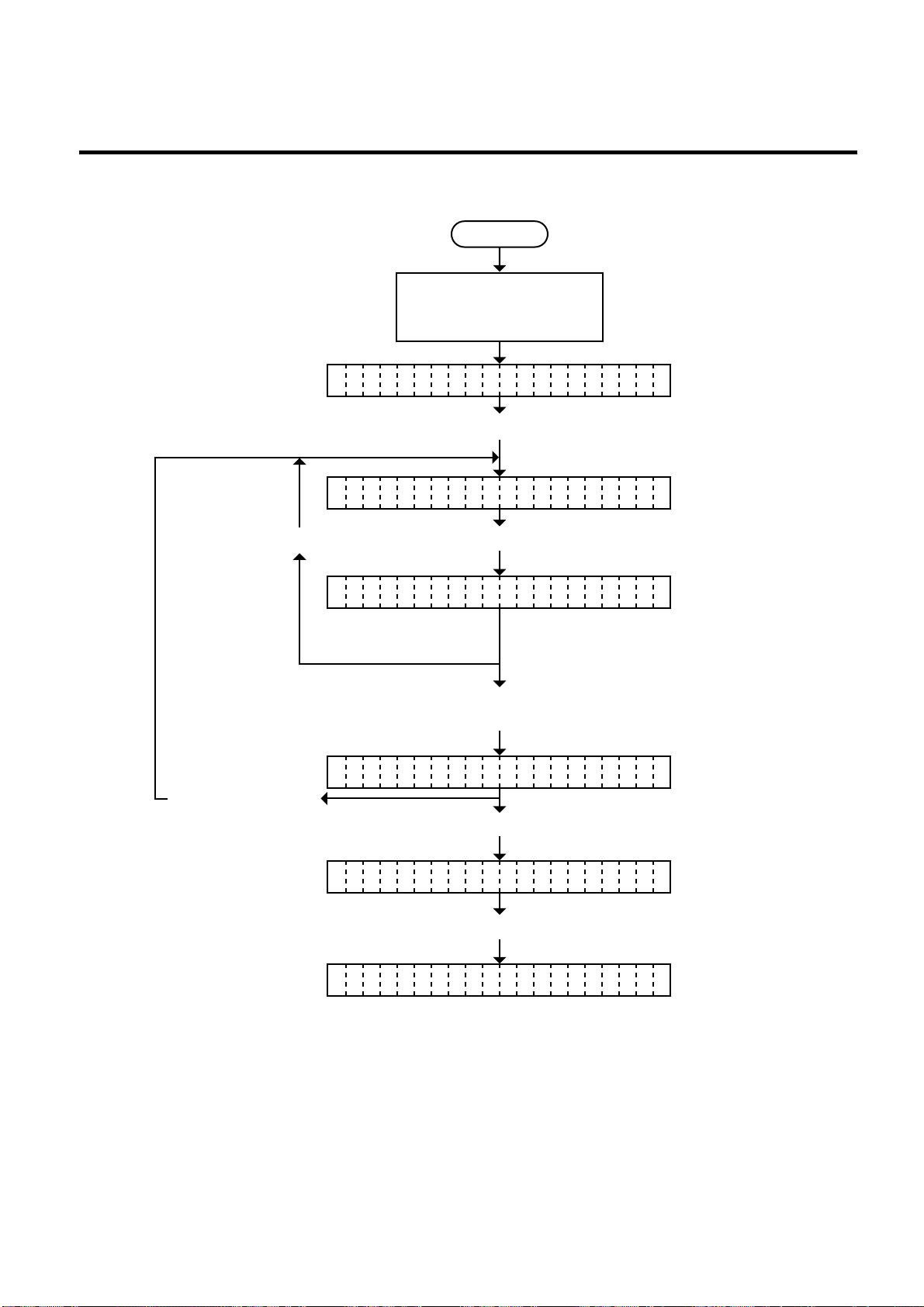
6. DIAG. TEST OPERATION
6.6.2 Parameter Clear
EM18-33013
6.6 RAM CLEAR MODE
Power off
Turn on the power while
holding down the [FEED]
key and [PAUSE] key.
<1 DIAGNOSTI C V1.OA>
Press the [FEED] key four times.
<5 RAM CLEAR>
Press the [PAUSE] key. Press the [PAUSE] key.
NO RAM CLEAR
Press the [FEED] key twice.
(or press the [RESTART] key.)
Press the [FEED]
PA AMETER CLEARR
key and
[RESTART] key at
the same time.
Press the [PAUSE] key.
CO PLETEM
Turn off the power (See NOTE 1)
NOTE: Confirm that “COMPLETE” is displayed, then turn the power off.
6-57
Page 87
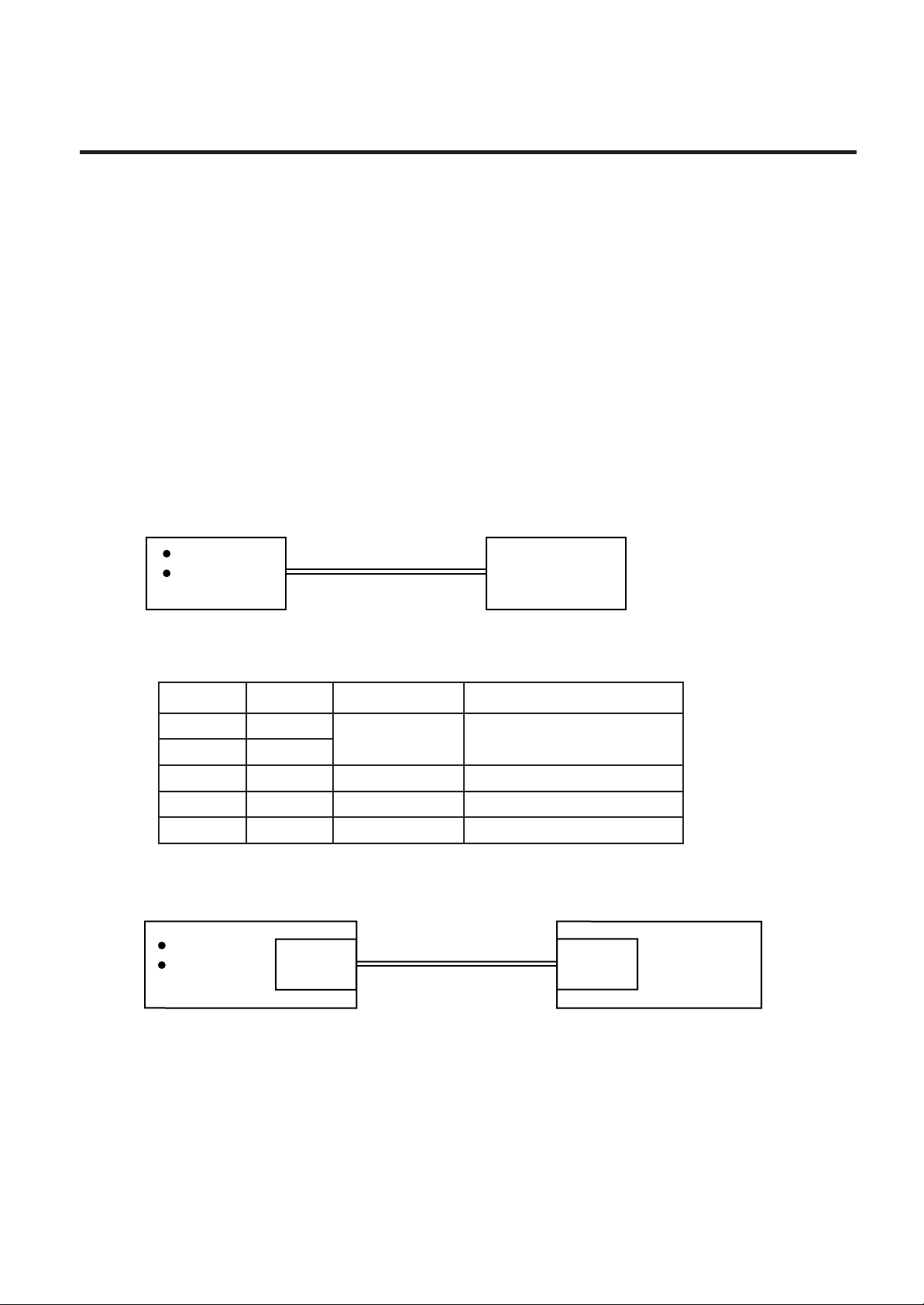
7. PROGRAM DOWN LOAD
(Revision Date Sep. 29, ’95)
EM18-33013
7.1 FLOPPY DISK
7. PROGRAM DOWN LOAD
The main program for the printer has been written onto the flash ROM. If the main program is
upgraded, due to the addition/change of the specification, down load the main program from the PC to
the printer with the down-load floppy disk and RS-232C interface or high speed PC interface.
7.1 FLOPPY DISK
(1) Media.................... 3.5 inches (2DD)
(2) System disk .......... 1 disk (This floppy disk contains the main program written onto the printer and
the tool program for down load.)
7.2 SETUP
The transmission control code for the printer must be set to either the automatic selection or manual
selection (ESC, NUL, LF). For details, refer to Section 6.3.8 Control Code Selection.
(1) Program down load with RS-232C interface
IBM PC/AT
Compatible
machine
RS-232C cable
Printer
Connect the PC to the printer with an RS-232C cable. Set the DIP SW2 on the CPU PC board of the
printer as follws:
#WSsutatSnoitcnuFnoitpircseD
1FFO
2NO
3FFOtib1htgneltibpotS
4NOtib8htgnelataD
5FFOoNytirapfoecnesba/ecneserP
SPB0069deepSnoissimsnarT
(2) Program down load with high speed PC interface
IBM PC/AT
Compatible
machine
BPC PC
board
Printer cable
BPE PC
board
Printer
Fig. 7-1
Fig. 7-2
Install the BPC and BPE PC boards in the PC and printers, respectively, and connect both boards
to each other with the special printer cable after referring to the Maintenance Manual Section 3.1.
Refer to the Owner’s Manual enclosed with the high speed PC interface board kit to set the DIP SW
on the BPC PC board and to install the BPC driver in the PC (hard disk drive).
7-1
Page 88
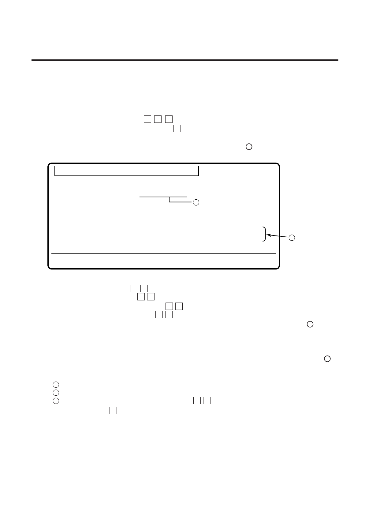
7. PROGRAM DOWN LOAD
7.3 DOWN LOAD PROCEDURE
EM18-33013
7.3 DOWN LOAD PROCEDURE
(1) Turn the PC power on.
(2) Turn the printer power on.
(3) Inset the program down load floppy disk into the PC.
(4) Change the drive to A. Type A :
(5) Start the batch file “PDL”. Type P D L
Or copy the contents of the floppy disk in to the hard disk and start the program in the hard disk.
(6) After starting the batch file “PDL”, the following menu is displayed. indicates the main program
version.
↵
↵
A
This is the down load program for B-X
DD-MM-YYYY
This program down line loads
the program file (Version V1.OA) to the B-X
Select the communication device. [ ]
A
( 1=RS-232C , 2=High Speed PC interface )
Are you sure ? (Y/N) [ ]
(Pressing the <Y key> will transmit the program file.)
To end the program press the <F1 key>
B
Fig. 7-3
(7) Select the interface.
• RS-232C interface 1
• High speed PC interface 2
(8) Start the main program transmission. Y
When changing the interface, press N and go back to step (7).
(9) While the main program is being transmitted, the following message is displayed in line . “###“
↵
↵
↵
↵
B
in the message, a running count, from 0 through 128 is shown indicating the number of KB
transferred.
** Now transmitting (###/128KB)**
(10) When the transmission is successfully completed, the following message is displayed in line .
B
End of transmission. Continue (Y/N) ? [ ]
• To continue
1 Turn the printer power off and exchange the printer with another one.
2 Turn the printer power on.
3 Start the main program transmission. Y
• To terminate N
↵
↵
7-2
Page 89
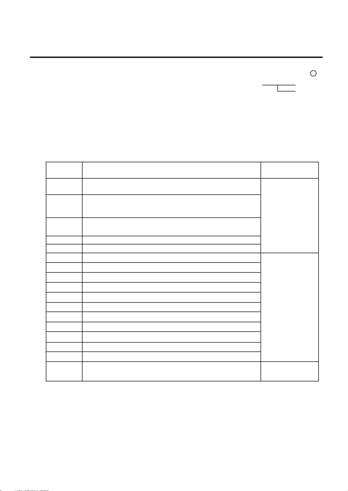
7. PROGRAM DOWN LOAD
EM18-33013
7.4 ERROR CODE
(11) When an error occurs, the following message is displayed together with the error code in line .
B
The following error occurred during transmission. (ERROR=##)
Press any key to retry.
Error code
Doing so will revert to the displayed described in step (6). Refer to the error code to find the cause
of the error. then retry the down load.
(12) After terminating the down load, refer to the Maintenance Manual Section 6.2 SELF TEST MODE
and perform diagnostic printing. Check that the printer operates properly and the main program
version and checksum is printed on the label.
7.4 ERROR CODE
edoCrorrE
)#(
60
70
05
15.MORhsalfehtfognittamrofgnirudderruccororreeteleD
75.atadmargorpnoissimsnartehtniderruccororremuskcahC
18"L"ottrevnoctonsilangistseuqernoissimsnartatadegamI
28ytpmetonsiecafretnideepshgihehtfoOFIFataD
rorrenoitacinummoC
rorrenoitacinummoC
.MOR
rorrEskrameR
).sisylanadnammocgniruddetcetedsirorrE(
gnirudderruccororregnimarfrororrenurrevo,rorreytiraP(
).C232-SRhtiwnoitacinummoc
hsalfehtotnonettirwgniebsawatadelihwderruccororreetirW
ehtmorfsutatS
retnirp
88.C232-SRniatadgnitawanehwdeviecersisutatsdenifednU
98.ecafretniCPdeepshgihehtnidetcetedsiyrracLTCOInA
09.derruccororreretemarapA
29.C232-SRniderruccororrenurrevonA
39.C3232-SRniderruccororreytirapA
49.C232-SRniderruccororregnimarfA
59.C232-SRnidetcetedsikaerbA
79.C232-SRniderruccororrenepo1MOC
89 .dnammocputesgnidaolehttsniagadeviecersisutatsdenifednU
99
sinoitarepognidaolehtnehwdeviecersisutatsdenifednU
.detanimret
CPnidetcetedrorrE
Check the following when an error occurs:
• The printer power is turned on.
• The RS-232C cable or high speed PC interface cable is connected properly.
• The DIP SW on the CPU PC board or BPC PC board is set correctly.
• With the high speed PC interface, that the BPC/BPE PC boards are installed in the PC/printer properly.
That the BPC driver is installed in the PC (hard disk drive) properly.
7-3
 Loading...