

TEATRONICS LIGHTING CONTROLS,TEATRONICS LIGHTING CONTROLS, INC.INC.
Owner's Manual
PROCON II
LIGHTING CONTROL CONSOLE
PROCON II
Lighting Control Console Page//
TEATRONICS LIGHTING CONTROLS, INC.
1236 Los Osos Valley Rd., Ste. G
Los Osos, CA 93402
Phone: (805) 528-6900
FAX: (805) 528-9345
12/01/94
12/05/97

TEATRONICS LIGHTING CONTROLS,TEATRONICS LIGHTING CONTROLS, INC.INC.
INTRODUCTION
Thank you for buying a Procon Controller from Teatronics Lighting Controls, Inc.. Before you
read this owner’s manual, examine your equipment carefully for damage or discrepancies in the
packing list. If shipping damage is evident, contact your carrier immediately to file a claim.
Contact our sales department for mysteries concerning your order or packing slip at (805) 5286900 (8:30 - 4:30 Pacific Time).
PROCON II
Lighting Control Console Page//
12/01/94
i

TEATRONICS LIGHTING CONTROLS,TEATRONICS LIGHTING CONTROLS, INC.INC.
TABLE OF CONTENTS
RECEIVING YOUR EQUIPMENT ...................................................................................... i
TABLE OF CONTENTS ..................................................................................................... ii
INTRODUCTION ................................................................................................................ 1
SETUP AND CONNECTION ..............................................................................................2
OPERATION (PROCON II ONE-SCENE) ...........................................................................4
OPERATION (PROCON II TWO-SCENE) .......................................................................... 5
ADJUSTMENTS.................................................................................................................. 8
CONTROL OUTPUT PINOUT ............................................................................................9
MAINTENANCE ...............................................................................................................10
IN CASE OF TROUBLE ....................................................................................................11
LIMITED WARRANTY..................................................................................................... 13
SCHEMATICS
PROCON II
Lighting Control Console Page//
12/01/94
ii

TEATRONICS LIGHTING CONTROLS,TEATRONICS LIGHTING CONTROLS, INC.INC.
INTRODUCTION
Thank you for buying an Teatronics Lighting Controls, Inc. control console. Please read this
manual thoroughly to understand your unit and to insure that you get the most out of it.
The purpose of the owner’s manual is to assist you in becoming familiar with the Procon II: its
installation, operation, troubleshooting and maintenance. Ownership of a sophisticated piece of
electronic equipment involves more than just “buy it and use it”. The Procon II was designed in
response to users’ requests for many features they felt were important. These features lie beneath
the simplicity of appearance. To fully appreciate them and what they can do for you, read on.
The Procon II series are available in one or two scene configurations. This analog manual
console derives its source of power from the dimmer pack. It works well with the entire line of
Teatronics Lighting Controls, Inc. dimmer packs as with packs made by other manufacturers of
remote controlled dimming equipment.
Take the time and care to follow these instructions and your Procon II console should provide
you with long-lasting quality lighting control.
PROCON II
Lighting Control Console Page//
12/01/94
1

TEATRONICS LIGHTING CONTROLS,TEATRONICS LIGHTING CONTROLS, INC.INC.
SETUP AND CONNECTION
MECHANICAL INSTALLATION
The Procon II console has no limitations on its physical orientation; it may be mounted in any
position without damage to the unit. Personal preferences usually dictate the best placement.
All controls should be easy to reach by the operator with emphasis on smooth operation of the
slide controls and easy access to the bump buttons. As with all electrical equipment, moisture
can cause permanent damage to the circuitry; the console should be protected against rain, and
beverages.
ELECTRICAL INSTALLATION
All that is required to connect the control to the dimmer pack(s) is a remote cable or cables of the
proper type. This cable is connected to the output jack on the back of the console and to the
input jack on the back of the dimmer pack(s). Each connector is keyed to assure proper connection;
when the keys are lined up the connectors will slide together with ease. Do not force the
connectors! Broken connectors are not covered by the warranty.
INTERFACE WITH DIMMERS
Remote control lighting consoles use a low voltage (usually DC) control signal to vary the
outputs of the dimmer packs. The lighting industry had standardized on “zero to ten” volt DC.
Unless a different control was voltage was specified when your console was ordered, it is adjusted
for zero to ten volt operation. When adjusted for zero to ten operation, the control voltage is
zero volts when a channel is off, ten volts when a channel is on full, and varies linearly between
the two extremes.
Each channel has its own control wire which runs to the dimmer pack(s). There are two types of
standard output connectors on the Procon II series depending on which type of dimmer you are
using. One SRC or 3-XLR connectors are required for each set of twelve channels of control.
Below are instructions for use of both types of configurations.
SRC CONTROL CABLES - GLX/DPI/Genesis
Connection of the controller is very simple. It requires one 12-channel standard cable for every
12 channels of dimming.
When used with GLX/DPI/Genesis, connect one cable to each 12-channel output on the control
console and the other to a 12-channel pack. Repeat the connections for each group of 12
channels on the console.
PROCON II
Lighting Control Console Page//
12/01/94
2

TEATRONICS LIGHTING CONTROLS,TEATRONICS LIGHTING CONTROLS, INC.INC.
SETUP AND CONNECTION (continued)
XLR CONTROL CABLES - WARRIOR
Connection to the controller is very simple. It requires one 4-channel cable for every four
channels of dimming.
In use with Warrior dimmers, connect one cable to each 4-channel console output and the other
end to a Warrior. A glowing Light Emitting Diode (LED) on the console will show that it is
receiving power. Repeat the connections for each group of four channels on the console.
PROCON II
Lighting Control Console Page//
12/01/94
3
TEATRONICS LIGHTING CONTROLS,TEATRONICS LIGHTING CONTROLS, INC.INC.
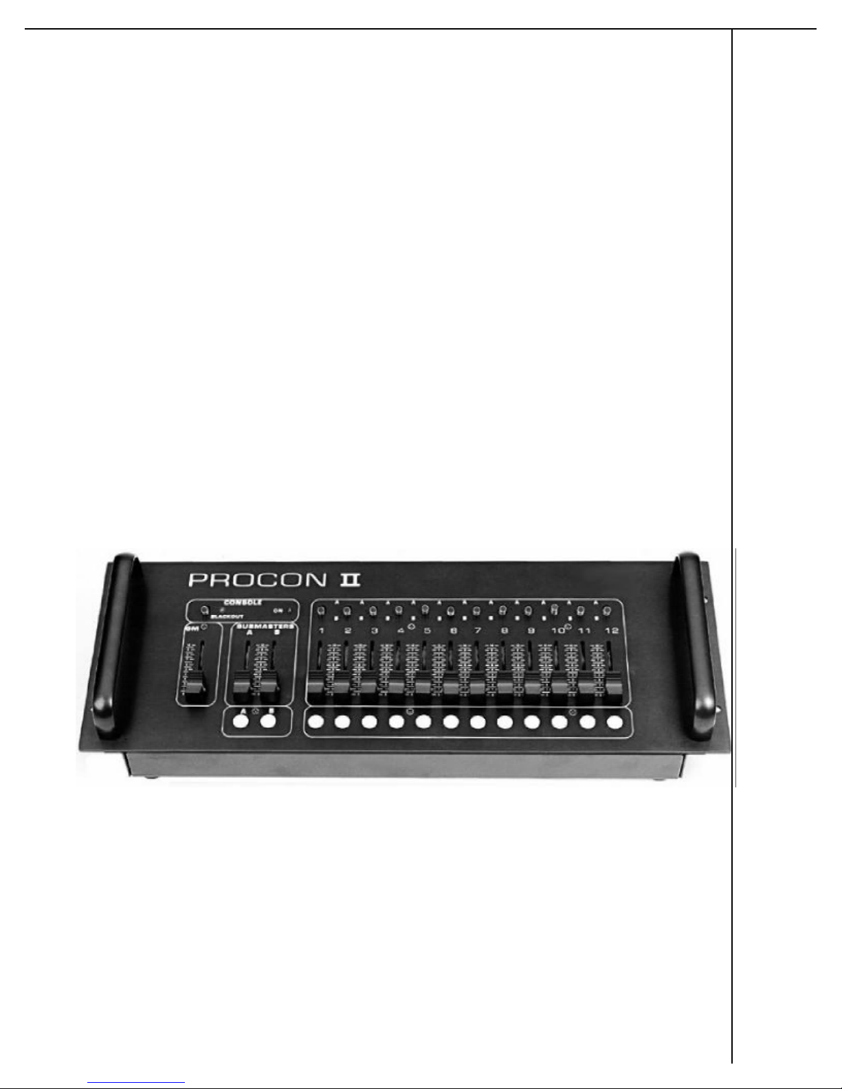
OPERATION
(Procon II One-Scene)
Teatronics Lighting Controls, Inc. one-scene consoles are designed to be used with the Warrior
and the GLX line of dimmer packs.
Each channel has a mode selector switch “1” and a calibrated linear control “2”. In the up, or
“A” position, the A Submaster will proportionally adjust the output of that channel (and all
other channels set to “A”). In the down, or “B” position, that channel will be proportionally
controlled by the B Submaster (along with all others set to “B”).
The BLACKOUT switch “3” is located above the Grand Master. Operating this switch downward
causes an immediate cutoff of the output of all dimmers on the console. Turning the switch back
on without changing the dimmer settings will cause all channels to “switch on” to the setting
indicated.
A green LED “4” directly above the submaster, controls indicates that the console is on and
receiving power. A Grand Master control “5” is provided for total control console proportioning.
BUMP BUTTONS “6” cause the output of the respective channels to go to “full” when depressed
by the operator. These BUMP (or flash) buttons override all channel and submaster controls. In
addition to one per channel, each A or B has a bump button as well, allowing a group of dimmers
to be flashed.
3
4
1
5
PROCON II
Lighting Control Console Page//
2
6
12/01/94
4

TEATRONICS LIGHTING CONTROLS,TEATRONICS LIGHTING CONTROLS, INC.INC.
OPERATION
(Procon II Two-Scene)
The operation of the Procon II two-scene may be best understood by dividing the various controls
into groups. The groups for the purpose of this manual are: The Master Section (1), The
Crossfader Section (2). The Submaster Section (3). The Channel Sectiona (4). The Effects
Section (5) (see page 7 for diagram).
MASTER SECTION (1)
The controls grouped into the master section are the Grand Master slider and the Blackout
switch. These two controls have a global effect on the rest of the console. The Grand Master
slider proportionally adjusts the level of the scene selected by the crossfader.
When the Blackout switch is in the up position, the console is in normal operation with the
indicator LED showing green. When in the down position, the console is in Blackout mode,
taking all channel outputs to a level of zero. The LED changes to red when the console is in the
Blackout mode.
CROSSFADER SECTION (2)
The controls grouped into the crossfader section are the X scene slider and the Y scene slider. In
a two scene console typically one scene is ‘active’ while the other scene is being pre-set for the
next lighting cue. The crossfader controls select which is the active scene, and which is the
inactive scene (which may be altered without affecting the outputs). The X scene slider affects
the top row of channel controls (the X scene) whereas the Y scene slider affects the bottom row
of channel controls (the Y scene). The Y scene slider is ‘up-side-down’ from all other sliders on
the console in that it’s output is at maximum when the slider is all the way down (toward the
operator) and is at zero when the slider is all the way up (toward the chase control). The Y scene
slider is oriented this way so that smooth fades from one scene to the other may be made by
moving both the X and the Y scene sliders together. However, the two scene sliders do not have
to be moved together. By splitting the crossfaders, one scene may be faded out before the other
scene is faded in, or the inactive scene may be faded in before the active scene is faded out.
PROCON II
Lighting Control Console Page//
12/01/94
5

TEATRONICS LIGHTING CONTROLS,TEATRONICS LIGHTING CONTROLS, INC.INC.
OPERATION/Two-Scene (continued)
SUBMASTER SECTION (3)
The controls grouped into the submaster section are the A, B, C, and D submaster sliders and
corresponding bump buttons. Each submaster controls a group of channels, and in turn is
controlled by the Grand Master (through the crossfader). The channels that each submaster
controls are selected by the channel selector switches as described in the next section.
CHANNEL SECTION (4)
The controls grouped into the channel section are all the channel sliders, and the associated
submaster selector switches. Up until this point, the controls that have been discussed typically
affect a group of channels. The sliders and switches in the channel section affect only their own
channel, that is the controls for channel 1 have no affect on the output of channel 2 or any other
channel. On the Procon II there are four controls for each channel (five if you count the momentary
button described below). These controls are the two sliders (X and Y scene) and a submaster
selector switch for each slider. Each channel’s output level is dependent on the settings of a
number of sliders and switches. The various possibilities of switch settings are numerous. A few
of the possibilities are discussed here and should give the user a fair understanding of the versatility
of the Procon II.
Standard two scene operation without submastering can be accomplished by placing all the
submaster sliders at full. Since the submasters are all at full, the position of the submaster
selector switches on each channel does not affect the output, however in the interest of neatness,
it is recommended that all the switches be switched either up or down. In this configuration, the
Grand Master controls the overall level of all channels and the crossfaders are used to fade from
the X scene to the Y scene.
Two scene operation with submastering is the same as above, except the submasters may be used
to adjust the overall level of the channels which are switched to them. In this configuration some
of the channels in each scene will be switched to one submaster and some to the other. The
crossfader controls which two submasters are active; A & B are active if in the X scene, C & D
are active if in the Y scene.
EFFECTS SECTION (5)
The controls grouped into the effects section are the bump controls: bump on/off switch, and
bump buttons on each channel and each submaster, and the chase controls: chase on/off switch,
forward/reverse switch, 8-channel/4-channel switch, rate slider, and level slider. The bump
buttons (also called momentary or flash buttons) are used to alter the channel (or submaster)
level to full without moving the slider. The bump on/off switch disables the bump buttons when
in the off position. When the bump switch is on, the bump button adds the channel to the output
of the console just as if the associated slider had been moved to full.
PROCON II
Lighting Control Console Page//
12/01/94
6

TEATRONICS LIGHTING CONTROLS,TEATRONICS LIGHTING CONTROLS, INC.INC.
OPERATION/Two-Scene (continued)
The Procon II includes a chase unit which chases the first four or eight channels of the console
depending on the position of the 8 channel/4 channel switch. The chase on/off switch turns off
the chase unit so that if the chase level is accidently brought up, the outputs will not start chasing.
The forward/reverse switch determines the direction of the chase; in forward mode, the chase
sequence starts with channel 1 and counts up. In reverse mode, the chase sequence starts with
either channel 4 (if in 4 channel mode) or channel 8 (if in 8 channel mode) and counts down. The
chase rate slider controls how long the chase leaves one channel on before sequencing to the
next. The level slider controls the level each channel is sequentially brought up to. The chase
unit in the Procon II ‘piles-on’ to the outputs of channels one through eight. That is, it only
serves to increase the level of the channel above what it is set at. Therefore, if channels one
through eight are at 80%, the chase will have no effect on the outputs until the chase level
control is brought above 80% (a setting of 8). The chase level is not affected by the Grand
Master but is affected by the Blackout switch.
PROCON II
Lighting Control Console Page//
12/01/94
7

TEATRONICS LIGHTING CONTROLS,TEATRONICS LIGHTING CONTROLS, INC.INC.
ADJUSTMENTS
The Procon II console has an internal adjustment to set the control voltage at the high end of the
slide pot travel. This adjustment is usually factory set for zero to ten volt operation. If other
than zero to ten volt operation is desired (and was not specified when the console was ordered)
the adjustment may be altered to yield the correct control voltage, so long as the control voltage
falls within the limits of the Procon II’s circuitry. Any voltage from 9.1 to 12.6 may be obtained
at the Procon II’s outputs.
PROCON II
Lighting Control Console Page//
12/01/94
8

TEATRONICS LIGHTING CONTROLS,TEATRONICS LIGHTING CONTROLS, INC.INC.
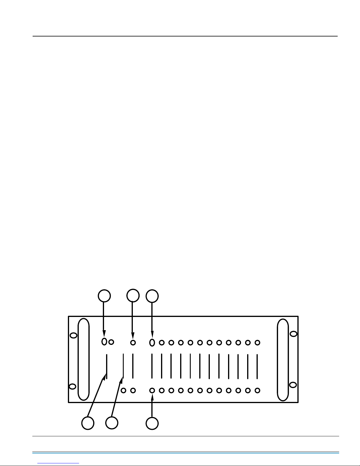
CONTROL OUTPUT PINOUT
CONTROL OUTPUT
CANNON SRC-16
(Facing the Chassis Plug)
Pin Number
1
2
3
4
5
6
7
8
9
10
11
12
13
14
15
16
Output Connections
Signal Common
Figure 1
Function
Channel 1
10
11
+15 Volts
None
None
Channel 12
2
3
4
5
6
1
7
8
9
16
CONTROL OUTPUT
XLR 5 PIN
(Facing the Chassis Plug)
1
2
3
4
5
Case
Signal Common
PROCON II
Lighting Control Console Page//
Channel 1
+15 Volts
1
5
2
3
4
12/01/94
9

TEATRONICS LIGHTING CONTROLS,TEATRONICS LIGHTING CONTROLS, INC.INC.
MAINTENANCE
The Procon II console requires no maintenance, other than keeping dust and liquids out of the
console. The console should be covered when not in use to prolong the service life of the slide
pots. Dirt and moisture are a slide pot’s worst enemy. A slide pot’s second worst enemy is the
do-gooder who sprays WD-40 into them. WD-40, volume control cleaners, tuner cleaners, and
similar products dissolve the lubricant inside the slide pot. This will shorten the life of the pot
and make operation less smooth. Only when a slide pot is so worn out that it must be replaced
anyway should WD-40 or the like be used; in this case spray cleaners may prolong the life long
enough to order replacement slide pots.
PROCON II
Lighting Control Console Page//
12/01/94
10

TEATRONICS LIGHTING CONTROLS,TEATRONICS LIGHTING CONTROLS, INC.INC.
IN CASE OF TROUBLE
The Procon II is a solid-state analog control console. Of the components used in lighting
systems, this console is probably the least likely to fail. The following paragraphs may help in
the event the lighting system fails to work properly.
First lets get the obvious things out of the way; check that the console is connected to the
dimmers and that the dimmers are on. Also be sure the loads are connected and not burned out.
Next, and most obvious, is to make sure that the “on” LED indicator is lit and the console is
NOT in Blackout.
Now that the obvious things are out of the way we can try to isolate the problem further. If the
“on” indicator LED is not lit, unplug the control cable from the console and measure to see if
the +15 volt supply voltage is present. If you have 5-pin XLR cables you will measure between
the connector case and pin 5, or if you have a SRC cable then measure between pin 15 (gnd) and
pin 12 (+15V). In either case if you do not have 15 volts DC present the control console is most
likely o.k. and we recommend you proceed to the owners manual for the dimmer. If 15 volts is
present, go to the next paragraph.
Plug the control cable back into the console, making sure the connector fits snugly, but do not
force the connector. The connectors are keyed to ensure a proper connection. If you are using
XLR type control cables make sure you are plugged into the first connector (1-4) of the console
since this is where the console gets its power. If you still have no LED indicator the console
most likely has failed and should be returned to the factory for repair.
If you have a green “on” LED indicator, but no control of the dimmers go through the following
routine. Place the Grand Master slide pot at full, all submasters at full, all channels at full, and
the crossfaders both at the full position. If you still have no response, return console to the
factory.
If, after performing these tests, you still cannot get proper operation, you may send your unit to
the factory service center, freight prepaid, with a note describing the specific complaint and the
results of the checks noted above. Send to:
Teatronics Lighting Controls, Inc.
1236 Los Osos Vallet Road
Suite G
Los Osos, California 93402
PROCON II
Lighting Control Console Page//
12/01/94
11

TEATRONICS LIGHTING CONTROLS,TEATRONICS LIGHTING CONTROLS, INC.INC.
IN CASE OF TROUBLE (continued)
All units need to be scheduled for return. Customers who wish to return units for repair need to
obtain an RMA Number prior to sending their unit back to; 1) allow coordination of the
technicians workload and , 2) insure that units not currently supported by the factory are not
sent in without permission.
Be sure to PACK THE UNIT WELL and insure it for its replacement value. Save and reuse the
original factory packing materials, or ship it in a road case if possible.
Those who wish to do their own repairs may buy parts from the factory. Unauthorized repairs
such as this will void the warranty and the buyer may be charged for subsequent factory repair,
even though the product may have originally been covered by the warranty. Call the factory
service department for any information about our service policy, ordering parts or for help
repairing a unit. The phone number is (805) 528-6900 weekdays from 8:00 am to 5:00 pm
Pacific Time.
PROCON II
Lighting Control Console Page//
12/01/94
12

TEATRONICS LIGHTING CONTROLS,TEATRONICS LIGHTING CONTROLS, INC.INC.
LIMITED WARRANTY
Teatronics Lighting controls, Inc. (TLC) agrees that its products shall be free from defects in
material or workmanship for a period of one year from date of delivery. Said warranty will not
apply if equipment is used in conditions of service for which it is not specifically intended. The
manufacturer is not responsible for damage to its apparatus through improper installation,
physical damage, or poor operating practice.
TLC's sole responsibility under this warranty shall be to repair or replace, at TLC's discretion,
such parts as shall be determined to be defective upon inspection by TLC or their authorized
agent. Such equipment shall be replaced or put in operating condition, free of all charges
except transportation, and the correction of any defects by repair or replacement by TLC shall
constitute fulfillment of all obligations to the original purchaser or retail customer. FREIGHT
TERMS ON WARRANTY REPAIRS ARE FOB TLC FACTORY OR DESIGNATED REPAIR
FACILITY. Collect shipments or freight allowances shall not be acceptable. TLC does not
assume responsibility for unauthorized repairs to its goods, even when determined to be defective.
TLC shall not be liable for any incidental, general, or consequential damages in case of any
failure to meet the conditions of any warranty or shipping schedule. Nor will any claim be
allowed for labor costs, loss of profits or income, repair costs, or any other expenses incidental
to replacement or repair of the item under said warranty.
The owner's obligations during the warranty period described herein are to notify TLC in writing
within ONE WEEK (7 calendar days) of any suspected defect, and with TLC's authorization
(RMA), to return the item or apparatus prepaid to the TLC factory.
No other representations, guarantees, or warranties, expressed or implied, are made by the
manufacturer in connection with the manufacture and sale of its equipment. This warranty is
nontransferable and applies only to the original purchaser or retail customer.
Teatronics Lighting controls, Inc.
1236 Los Osos Valley Road, Suite G
Los Osos, Ca 93402
PROCON II
Lighting Control Console Page//
12/01/94
13
 Loading...