


User manual 1
User Manual Version 3.0
Plasma Power source
Plasma CUT 65
Item number:
294-005000-00000
(CUT 65 with torch length 8m)
Plasma CUT 85
Item number:
294-005010-00000
(CUT 85 with torch length 8m)
Plasma CUT 105
Item number:
294-005020-00000
(CUT 105 with torch length 8m)
Plasma CUT 125
Item number:
294-005030-00000
(CUT 125 with torch length 8m)
THIS MACHINE IS TO BE USED ONLY FOR METAL CUTTING OPERATIONS
and determined for professional use only!

User manual 2
Table of Contents
GENERAL INSTRUCTIONS 4
WARNING! 4
FOR YOUR SAFETY. READ THE INSTRUCTIONS! 5
DANGER 5
WARNING 5
CAUTION 5
IMPORTANT WARNING 6
ELECTRIC SHOCK CAN KILL 6
NOISE CAN DAMAGE HEARING 6
CUTTING CAN CAUSE FIRE OR 6
EXPLOSION 6
SMOKE AND GASES CAN BE 6
HAZARDOUS 6
HOT PARTS CAN CAUSE SEVERE BURNS 7
MAGNETIC FIELD CAN AFFECT PACEMAKERS 7
FLYING SPARKS CAN INJURE 7
PLASMA ARC CAN INJURE 7
PLASMA CUTTING CAN CAUSE INTERFERENCE 7
OVERUSE CAN CAUSE OVERHEATING IN THE EQUIPMENT 7
CAUTION WHEN CUTTING AROUND GAS CYLINDERS 7
LIGHTNING ARC CUTTING CAN BURN EYES AND SKIN 8
SPECIFICATIONS 9
Specifications – plasma power source 9
Spezifikation – Plasmastromquellen 65 -125 (Continuation) 10
Duty Cycle 11
Dimensions and weight of the power source 11
Specifications – torches AP 65 -125 12
Torches dimensions / Hand torch dimensions 13
Mechanized torch dimensions (with or without rail) 13
SYMBOLS AND MARKING 14
Marking S 14
IEC symbols 14
INSTALLATION 15
The acquisition time of 15
Claims 15
Box contents 15
Power source location 17
Mains power connection 17
Connecting to autonomous generator 18
Connecting to ground 18
Power cable 19
Three phase power cable 19
Installation power cable 19
Installation the plug 20
The mass grip area 20
Installation the torch 21
Feeding the plasma gas 23
Additional gas filtration 23
Installation of the gas supply 24
Alignment of the torch AP 65 -125 Auto 24
Connection “ON/OFF” (Turn ON/Turn OFF) on the remote control 25
Connecting the machine interface CNC 25
CNC - Arc voltage connection 26
CNC - Activating external DC coil with an external power supply. 29

User manual 3
CNC - Activating an external AC coil with an external power supply. 30
CNC - Activating an industrial isolated module with an external power supply. 31
OPERATIONS 32
Controls and indicators 32
Control panel 33
Torch consumables installation 34
Torch consumables configuration 34
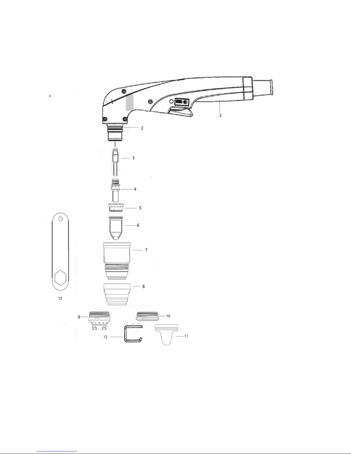
Torch parts 35
Torch consumables configuration (continued) 36
Torch parts 37
Mode selection 38
Check and adjust the gas pressure and current ( power ) 39
Operating the manual torch 40
Fix the mass clamp 41
Cutting start from the edge of the piece 41
Hand torch cutting technique 42
Piercings 43
Gouging 44
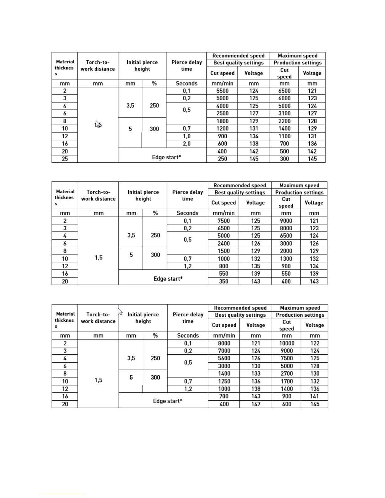
CUTTING CHART 45
Mechanized unshielded consumables for 45 Amps 45
Mechanized unshielded consumables for 65 Amps 46
Mechanized unshielded consumables for 85 Amps 47
Mechanized unshielded consumables for 105 Amps 48
Mechanized unshielded consumables for 125 Amps 49
MAINTENANCE 50
Routine maintenance 50
Consumables inspection 51
Replace the gas filter element 52
Disconnect electrical power and gas supply. Remove the filter bowl. 52
Remove the filter element from the filter housing.
52
Install the filter bowl. 52
Controls and indicators 53
Lighting indicators 53
Solution to basic problems 54
Electric system circuits draw 57
PARTS 58
Configuration of the torch consumables 58
Configuration of the torch consumables (continuation) 59
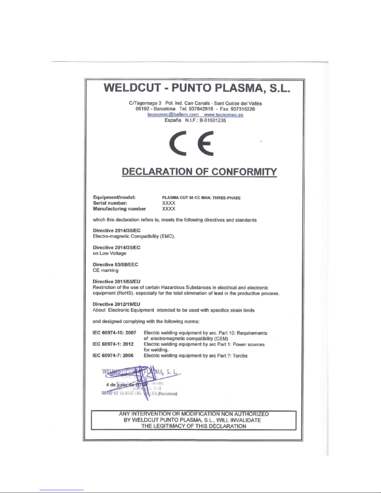
DECLARATION OF CONFORMITY 60
DOC TW CUT 65 60
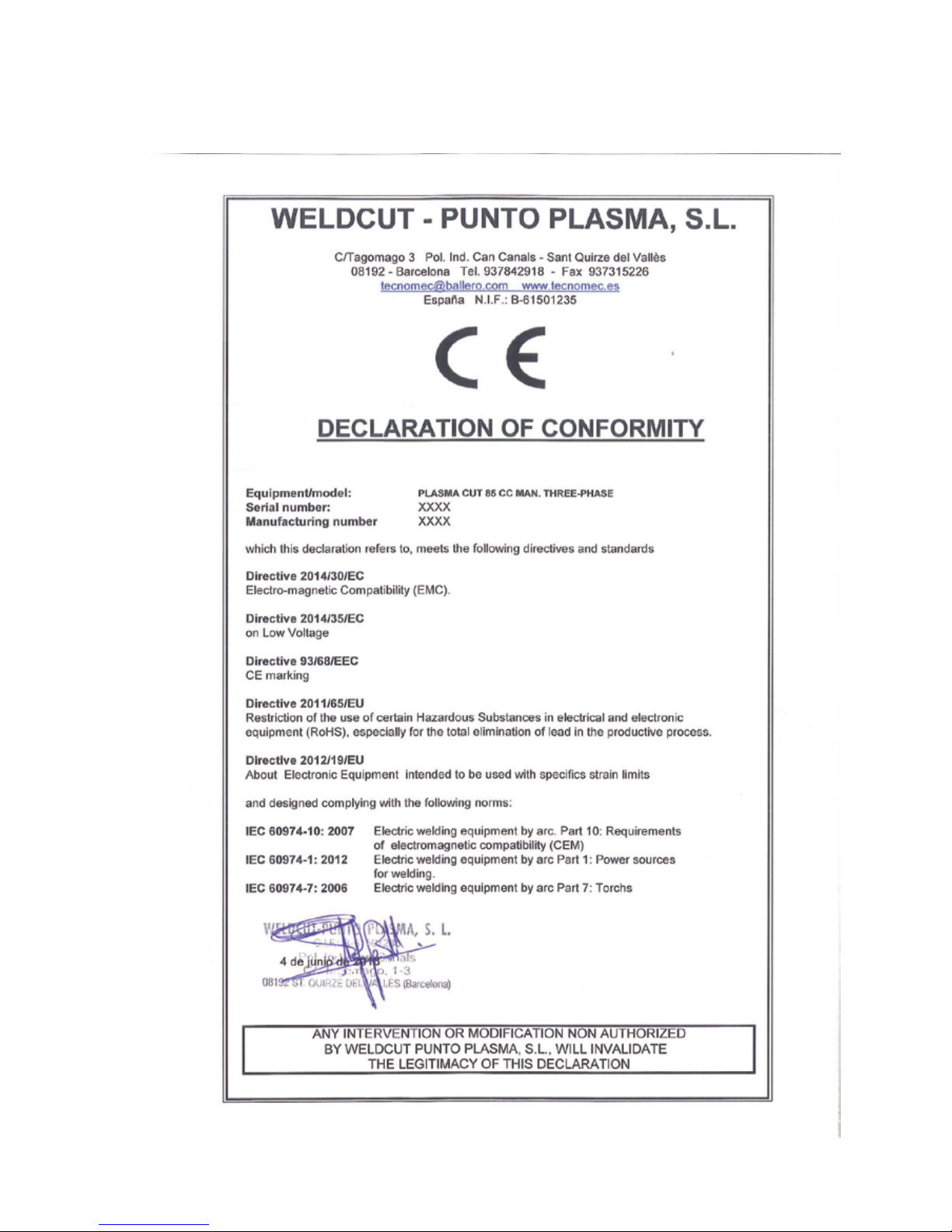
DOC TW CUT 85 61
DOC TW CUT 105 62
DOC TW CUT 125 63
MANUFACTOR AND DISTRIBUTOR INFORMATION 64

User manual 4
GENERAL INSTRUCTIONS
Read the operating instructions before to switch on the machine and start to work!
The operating instructions provide an introduction to the safe use of the products.
• Read and observe the operating instructions for all system components, especially
the safety instructions and warning notices!
• Observe the accident prevention regulations and any regional regulations!
• The operating instructions must be kept at the location where the machine is ope-
rated.
• Safety and warning labels on the machine indicate any possible risks.
• Keep these labels clean and legible at all times.
• The machine has been constructed to state-of-the-art standards in line with any
applicable regulations and industrial standards. Only trained personnel may operate, service and repair the machine.
• Technical changes due to further development in machine technology may lead to
a differing cutting behaviour.
WARNING!
In the event of queries on installation, commissioning, operation or special conditions
at the installation site, or on usage, please contact your sales partner or our customer
service department on +49 2623 9276400.
A list of authorised sales partners can be found at www.teamwelder.com.
Liability relating to the operation of this equipment is restricted solely to the function of the equipment. No other form of liability, regardless of type, shall be accepted.
This exclusion of liability shall be deemed accepted by the user on commissioning the
equipment.
The manufacturer is unable to monitor whether or not these instructions or the conditions and methods are observed during installation, operation, usage and maintenance
of the equipment.
An incorrectly performed installation can result in material damage and injure persons
as a result. For this reason, we do not accept any responsibility or liability for losses,
damages or costs arising from incorrect installation, improper operation or incorrect
usage and maintenance or any actions connected to this in any way.
TEAMWELDER Germany GmbH
Sälzerstraße 20a
D-56235 Ransbach-Baumbach
Deutschland / Germany
The copyright to this document remains the property of the manufacturer.
Reprinting, including extracts, only permitted with written approval.
The content of this document has been prepared and reviewed with all reasonable
care. The information provided is subject to change; errors excepted.
User manual 5
DANGER
Working or operating procedures which must be closely observed to prevent imminent serious and even fatal injuries.
• Safety notes include the „DANGER“ keyword in the heading with a general warning symbol.
• The hazard is also highlighted using a symbol on the edge of the page.
WARNING
Working or operating procedures which must be closely observed to prevent serious and even fatal injuries.
• Safety notes include the „WARNING“ keyword in the heading with a general warning symbol.
• The hazard is also highlighted using a symbol in the page margin.
CAUTION
Working or operating procedures which must be closely observed to prevent possible minor personal injury.
• The safety information includes the „CAUTION“ keyword in its heading with a general war-
ning symbol.
• The risk is explained using a symbol on the edge of the page.
Technical aspects which the user must observe to avoid material or equipment damage.
Instructions and lists detailing step-by-step actions for given situations can be recognised via
bullet points, e.g.:
• Insert the welding current lead socket into the relevant socket and lock.
FOR YOUR SAFETY. READ THE INSTRUCTIONS!
User manual 6
IMPORTANT WARNING
According to the European standard EN61000-312, which entered into force in December 2010, this
equipment is suitable for use with self-generating
power and private power networks. Its use in electric networks of public character does not conform
to the limits prescribed in the standard.
ELECTRIC SHOCK CAN KILL
Touching electrical parts could cause a
fatal shock or severe burns.
• Don’t touch the life electric parts.
• Wear dry insulated gloves, shoes and
protective clothing.
• Insulate yourself from work and ground using
dry insulating material and
non-flammable.
• The working area should be clean and dry.
• Switch OFF the machine for cleaning and
maintenance operations.
• Do not rape cables around your body.
• Turn OFF the machine when remain not used.
• Periodically check the supply hose, the
insulation must be intact. Replace the
hose immediately if damaged. Use the
machine with bare wires, uncoated, is
very dangerous.
• Before handling the cutting power
source must wait five minutes to ensure
complete discharge of the capacitors of
the machine.
• Keep your unit in good condition; repair
or replace damaged parts immediately.
Maintain unit according to manual.
CUTTING CAN CAUSE FIRE OR
EXPLOSION
Fire prevention
• Keep flammable items away from the
work area.
• Make sure the work area is a fire extinguisher,
and that it is in top condition for use.
• Ventilate the work area before using the slicer
when working in areas of potential fire risk.
Explosion prevention
• Do not cut in areas containing explosives,
flammable gases or vapours.
• Do not locate unit on, over, or near combustible
surfaces.
• Do not operate the machine in areas with an
atmosphere containing high concentrations of
dust, flammable gases or vapours.
• Never use the machine for cutting container of
flammable materials that
are not completely empty and clean, or
are under pressure.
SMOKE AND GASES CAN BE
HAZARDOUS
Induction heating of certain materials,
adhesives, and fluxes may cause fumes or
smoke.
Breathing these fumes and gases can be
hazardous to your health.
• Keep your head out of the smoke, do not
breathe the fumes.
• If inside, ventilate the area and / or us
an exhaust system near the cutting arc
to remove the smoke and gas cutting.
• If ventilation is poor, wear an approved
air-supplied respirator.
• Work in a confined space only if it is
well ventilated, or while wearing an
air-supplied respirator. The smoke and
gases from the heating process can
displace air and lower the oxygen level
causing injury or death. Be sure the
breathing air is safe.
NOISE CAN DAMAGE HEARING
Prolonged noise from some applications can
cause hearing damage.
• Use hearing protection or ear muffs if
nose level is high.
• Warn others about the dangers of noise.

User manual 7
HOT PARTS CAN CAUSE SEVERE
BURNS
• Do not touch hot parts bare handed.
• Allow cooling time before handling.
PLASMA CUTTING CAN CAUSE INTERFERENCE
• Electromagnetic energy can interfere with sen-
sitive electronic equipment such as computers,
or computer-driven equipment.
• Ensure that all equipment in the cutting area is
electromagnetically compatible.
• Ensure that the cutting machine is installed
and positioned according to this manual.
MAGNETIC FIELD CAN AFFECT PACEMAKERS
Prolonged noise from some applications can cause
hearing damage.
• Use hearing protection or ear muffs if
nose level is high.
• Warn others about the dangers of noise.
OVERUSE CAN CAUSE OVERHEATING IN THE EQUIPMENT
Prolonged noise from some applications can
cause hearing damage.
• Use hearing protection or ear muffs if
nose level is high.
• Warn others about the dangers of noise.
FLYING SPARKS CAN INJURE
During the cutting process, there can be
landslides incandescent material. Itching
can cause flying metal.
• Use face shield and safety glasses with
side shields.
• Use proper body protection to protect
your skin.
• Use earplugs and ears that are re-
sistant to flames to prevent sparks
from entering your ears.
PLASMA ARC CAN INJURE
The arc plasma is turned on immediately after
the torch switch is activated.
• Keep away from the torch tip, because it
can cut quickly gloves and skin.
• Do not place hands near the cutting path.
• Do not point gun toward oneself or to
another.
CAUTION WHEN CUTTING
AROUND GAS CYLINDERS
Gas cylinders containing gas under high
pressure, if damaged, there is a possibility of
explosion.
• Handle and use compressed gas cylin-
ders in accordance with local or national
codes.
• Never allow electrical contact between
the plasma arc and a bottle.
• Never expose cylinders to excessive heat,
sparks, slag or flames.
• Do not point gun toward oneself or to
another.

User manual 8
LIGHTNING ARC CUTTING CAN
BURN EYES AND SKIN
Arc rays from the cutting process produce intense
visible and invisible rays that can burn eyes and
skin.
• Use protective clothing made from durable,
flame-resistant material and foot protection.
• Use face protection (helmet or shield) with
filter lenses to protect your eyes right color and
face (see Table).
• Warn people you are close to the point of wor-
king them not to watch the arc cutting.

User manual 9
SPECIFICATIONS
Specifications – plasma power source
Model CUT 125 CUT 105 CUT 85 CUT 65
Voltage Supply 3x400+-15%Vac 3x400+-15%Vac 3x400+-15%Vac 3x400+-15%Vac
Frequency 50-60Hz 50-60Hz 50-60Hz 50-60Hz
Current Consumption 38A-30A 29A-27A 25A-22A 20A-17A
Maximum Power 26kVA-21kVA 20kVA-18kVA 17kVA-15kVA 13kVA-11kVA
No Load Voltage 300 Vdc 300 Vdc 300 Vdc 300 Vdc
Load Voltage 160Vdc 160Vdc 145Vdc 145Vdc
Power Performance 125A-110A 105A-95A 85A-70A 65A-50A
Maximum Cutting
Thickness
*FE/SS/AL
60/55/45 mm
*FE/SS/AL
50/45/35 mm
*FE/SS/AL
40/35/25 mm
*FE/SS/AL
30/25/15 mm
Recommended CuttingThickness
*FE/SS/AL
50/45/40 mm
*FE/SS/AL
40/35/30 mm
*FE/SS/AL
35/30/25 mm
*FE/SS/AL
25/20/15 mm
Optimum Cutting
Thickness
*FE/SS/AL
40/35/30 mm
*FE/SS/AL
35/30/25mm
*FE/SS/AL
30/25/20 mm
*FE/SS/AL
20/15/10 mm
Air Flow 200 L/min 200 L/min 180 L/min 180 L/min
Recommended Air
Pressure
5,5/6,5 Bar 5,5/6,5 Bar 5,5/6,5 Bar 5,5/6,5 Bar
Arc Ignition System Without HF Without HF Without HF Without HF
Recommended Compressor
7,5 CV/300L/
min.
7,5 CV/300L/
min.
5,5 CV/200L/
min.
7,5 CV/200L/
min.
Recom. Power Generator Group
30 KVA 25 KVA 20 KVA 15 KVA
Power Range 5-125A 5-105A 5-85A 5-65A
Protection Level IP 23 S IP 23 S IP 23 S IP 23 S
Insulation Class H H H H
Dimensions 270x810x500
mm
270x810x500
mm
230x655x450 mm230x655x450
mm
Weight Torch included 44 kg 42 kg 36 kg 32 kg
*Steel (FE), Stainless Steel (SS), Aluminum (AL)

User manual 10
Model CUT 125 CUT 105 CUT 85 CUT 65
Operating temperature -10 °C a +40 °C -10 °C a +40 °C -10 °C a +40 °C -10 °C a +40 °C
Norm IEC 61000-3-12 EC 61000-3-12 EC 61000-3-12 EC 61000-3-12
Gas type Air / Nitrogen Air / Nitrogen Air / Nitrogen Air / Nitrogen
Gas quality Clean, mois
ture-free,
without oil
Clean, mois
ture-free,
without oil
Clean, mois
ture-free,
without oil
Clean, mois
ture-free,
without oil
Gas inlet pressure and
flow
6,1 bar 200 l/
mm
6,1 bar 200 l/
mm
6,1 bar 200 l/mm6,1 bar 200 l/
mm
Spezifikation – Plasmastromquellen 65 -125 (Continuation)
*Steel (FE), Stainless Steel (SS), Aluminum (AL)
**IP - International Protection, 2 - No penetration of foreign bodies >12,5 mm, 3 - No penetration of
harmful spray water, S - Fan is during the water test
WARNING - Do not operate when it rains!

User manual 11
Duty Cycle
The duty cycle is the percentage of time, over a period of 10 minutes, the power source can
continuously cutting. The following diagram represents a duty cycle of 80%.
Dimensions and weight of the power source
8 minutes cutting
2 minutes resting
Weight power source
without torch.
Model CUT 65/85
32 kg - 36 kg
Model CUT 105/125
42 kg – 44 kg
High: 450 mm
Length: 655 mm
Width: 230 mm
High: 500 mm
Length: 810 mm
Width: 270 mm
Model CUT 65/85 Model CUT 105/125

User manual 12
Specifications – torches AP 65 -125
Cutting capacity CUT 65 CUT 85 CUT 105 CUT 125
Recommended capaci
-
ty [mm]
15 25 35 40
Maximum capacity 20 30 40 50
Severance capacity 30 40 50 60
Gouging capability
( metal removal rate
on Mild Steel )
6 kg/h 8 kg/h 10 kg/h 12 kg/h
Weight
Hand Lead 5m - 2,03 kg without consumables
Lead 8m - 2,85 kg without consumables
Lead 15m - 4,74kg without consumables
Lead 23m - 6,85 kg without consumables
Auto Lead 5m - 2,50 kg without consumables
Lead 8m - 3,40 kg without consumables
Lead 15m - 5,30 kg without consumables
Lead 23m - 7,30 kg without consumables

User manual 13
Torches dimensions / Hand torch dimensions
Mechanized torch dimensions (with or without rail)

User manual 14
SYMBOLS AND MARKING
Marking S
The mark S indicates that the power source and torch are suitable for use in environment with
danger of electrocution. The hand torches consumable parts must be protected to meet the
mark
S
IEC symbols
It is possible that the following symbols are present in the data plate plasma generator, control
labels and switches.

User manual 15
INSTALLATION
The acquisition time of
1. Verify that all items in your order have been received. Contact the supplier / manufacturer
of original equipment, if any item is damaged or has not arrived.
2. If there is evidence of damage, see Claims, below. All communications about this power
source should include the model number and serial number located on the back of the
generator.
3. Read safety section in this manual before installing and operating this equipment.
Claims
Claims for shipping damage – If the unit has been damaged in transit, you should complain to
the carrier. TEAMWELDER given a copy of the invoice packing upon request. If you need
additional assistance, please call Customer Service at the phone number listed at the end
of this guide or your authorized dealer TEAMWELDER.
Claims for defective merchandise or missing – All units shipped from TEAMWELDER have been
subjected to rigorous quality control. If any of the parts is defective or is not included, call your
dealer. If you need additional assistance, please call Customer Service at the phone number
listed at the end of this guide or your authorized dealer TEAMWELDER.
Box contents
Check the items that appears in the illustration shown. (CUT 65 - 125)
(Consumables starting kit / Air male and female connector)

User manual 16
f
f
f
Lift with crane.
Use an approved harness.
Keep the power source as
horizontal as possible.
Keep in place the cover.

User manual 17
Power source location
Place the plasma power source CUT 65 -125 with a minimum distance of 0.5m of space (both
front and back) to receive of the fan, for good ventilation.
Mains power connection
The CUT 65 -125 is a plasma generator capable of cutting at 380-400 Vac three phase. Use a
line disconnect breaker for each power input so that the operator can turn off the power supply
quickly in an emergency. Place the back of the machine with the switch so that it is easily
accessible to the operator. For a continious working, the operator must connect the machine
to a „Wall power breaker“ which is equal or over the level of consumption of the plasma power
source.

User manual 18
Connecting to ground
To that personnel safety, proper operation and to reduce electromagnetic interference (supply hose),
CUT 65 -125 must be properly grounded through the cable according to national or local electrical
codes. The three-phase service must be of the 4-wire cord with a protective, grounding, green or
green / yellow and must comply with national and local electrical requirements.
Connecting to autonomous generator
When using a generator to power the CUT 65 -125:
• Operating with the generator:
1. Set the output AC generator in three-phase.
2. Plug the power cord into the receptacle 65-125 CUT group.
3. Set the generator at maximum output (see chart below).
Model CE
Three-phase, 50/60 Hz, 380 – 400 Vac (Recommended 400 Vac for better performances)

User manual 19
Power cable
Use an extension line that national or local codes to be certified. The extension must be installed
by a licensed electrician. See the length requirements listed below.
Note: the unit was tested with a power cable 3 m for compliance with EMC standard EN50199.
Three phase power cable
CE models CUT 65 -105 come with power cord 4 mm2, 4 wires (3 phases plus ground).
CE models CUT 125 come with power cord 6 mm2, 4 wires (3 phases plus ground).
To operate the CUT 65 -125, use a plug that complies with national and local codes. A licensed
and qualified electrician should connect the power cord to the plug.
Installation power cable
1. Strip and prepare the power cables as shown below:
Unit CE
L1 Black(U) R
L2 Brown(V) S
L3 Grey(W) T
Hearth Green-Yellow

User manual 20
Green-Yellow
Brown
Grey
Black
Installation the plug
A licensed and qualified electrician should connect the power cord to the plug.
The mass grip area
Important:
Place dough in an area where no, or primer or paint. You have to go subject directly touching
clean metal.

User manual 21
Installation the torch
1. TURN OFF the power source
OFF (0) / Turn OFF
ON (I) /Turn ON
2. Unplug the socket from the power net.
3. Torch connector.
Safety Pin for connection of
plasma torches only, in
accordance with European
standards.

User manual 22
4. Addressing the key torch with key and dock connector.
Torch key
Female machine key
5. Once faced and well coupled to the
connector screw torch.

User manual 23
Feeding the plasma gas
The feed gas CUT 65 -125 can be shop air or compressed air cylinder. It should use a high-pressure regulator in any of the two types of power supply and should be capable of delivering gas to
the filter from the power supply to 200 l / min at a pressure of 6.0 bar.
Note: If the gas supply is not good, the cutting speed decrease, cut quality will deteriorate,
diminish the ability to cut the required thickness, and the life of the consumables will be shortened.
WARNING
Do not allow the gas pressure exceeds 8.0 bar. The filter bowl
could explode if the pressure exceeds.
Additional gas filtration
(Not necessary, just recommended)
Use set TEAMWELDER filtration system or use 3-stage filtration that binds, as shown, when site
conditions introduce moisture, oil or other contaminants into the air line.

User manual 24
Installation of the gas supply
1. Air attach
• The CE model has an adapter G1/4
• The male attach/adapter is in the consu-
mables box, located on the back side of the
machine closed with a black plastic cover.
2. Air hose
• Use an inert gas hose with a minimum
internal diameter of 10 mm and one
attach of G1/4 or a female quick connection located also in the back side of
the machine.
Alignment of the torch AP 65 -125 Auto
Mount the machine torch perpendicular to a given work piece, in order to get a vertical cut. Use
a ruler to align the torch at 0 ° and 90 °

User manual 25
Connection “ON/OFF” (Turn ON/Turn OFF) on the remote control
Inputs for arc starting with the machine torch FHT-125M are available through the connection
interface of the machine in the back of the power supply. Plug the remote TEAMWELDER (see
Parts List for part numbers) into the connector on the back panel.
Connecting the machine interface CNC
Are available through the machine interface (see the
figure above), signals for arc transfer and start, on the
back of the plasma generator. Plug the machine interface ( TELEC95072 ) into the connector of the rear panel.
Look at the table below to connect the interface cable to
the
machine cutting CNC.

User manual 26
CNC - Arc voltage connection
If the arc voltage is necessary to enable the control of the height of the torch, the client must
obtain an isolated 1.0 mm2, single pair, 300V or higher. The arc voltage signal is accessible in the
interface card machine as follows:
1. Turn off the power of the plasma generator.
2. Remove the screws that joined the top of the power source to the chassis. Separate the cover.
3. Push the cable through the gland located in the back of the power supply. Look at the figure
below.
User manual 27
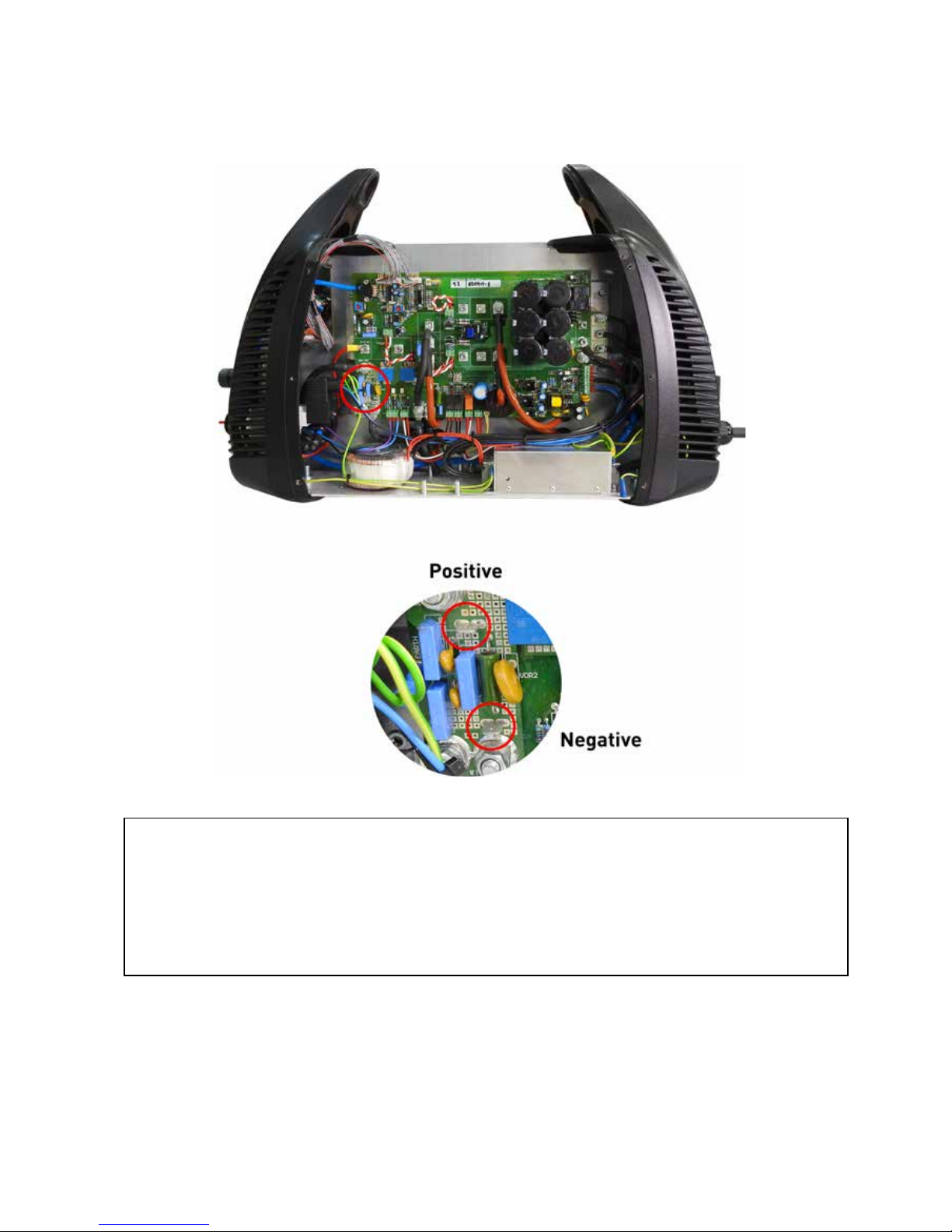
4. Arc voltage signal. See the below picture. Use insulated terminal ends of type “faston 6.35mm”
to connect to positive and negative.
Signal: Arc voltage ( to use in the torch height control )
Type: Output
Note: Full arc voltage. Without voltage divisor. 300Vdc maximum.
Positive + Vdc
Negative - Vdc
5. Tighten the cable gland.
6. Close the machine back.

User manual 28
1. Torch 2. Star-CNC 3. Arc. Trans 4. Solenoid
CNC - plasma cutting table is starting the movement of the exes X or Y.

User manual 29
CNC - Activating external DC coil with an external power supply.

User manual 30
CNC - Activating an external AC coil with an external power supply.

User manual 31
CNC - Activating an industrial isolated module with an external power supply.

User manual 32
OPERATIONS
Controls and indicators

User manual 33
Control panel

User manual 34
Torch consumables installation
Torch consumables configuration

User manual 35
Torch parts

User manual 36
Torch consumables configuration (continued)

User manual 37
Torch parts

User manual 38
Mode selection
Use it to cut metal into sheets / plates.
For optimal consumables duration.
Use it to cut the expanded metal.
Automatically re-start the pilot arc.
It is used to remove welding or gouging.
Switch ON (I) as shown.
Note: The cooling fan will only
work when the plasma needed.
Check that the gas pressure is above 3 bar in cutting and
grid mode and above 2 bar in gouging mode.
Check the lighting indicators
Check the indicator light ARE NOT illuminated. Safety indicator torch retaining cap.
Turn ON

User manual 39
Check and adjust the gas pressure and current ( power )

User manual 40
Operating the manual torch
Operating the safety torch trigger

User manual 41
Fix the mass clamp
Secure the clamp to the work piece that is going to work.
Hold the clamp as closed as possible to the cutting area to reduce exposure to
electromagnetic fields (EMC)
Do not hold the piece of piece to be release.
Cutting start from the edge of the piece
Keep the nozzle of the torch upright at the
edge of the piece.
Start cutting from the edge of the piece. Stop
at the edge until the arc has completely cut
through the part.
Then continue with the cut.

User manual 42
Hand torch cutting technique
Torch jogging without reducing the life of the
nozzle and the electrode.
When cutting, make sure the sparks out of the
bottom of the piece.
If sparks will jump up to the part, it is because
you are moving the torch too fast or without
enough energy.
Hold the torch vertically and watch the arc while cutting along the line.
Unshielded consumables. Keep away from the torch to the work of about 4.0 mm.
Shielded consumables. Please don`t tighten down the torch to the work piece
while cutting. Slide the torch carefully along the work piece to obtain a perfect cut.
• Put the torch along the cut, is easier to drive.
• For cutting thin material, reduce the amp to get a higher quality cut.
• For straight cuts, use a ruler as a guide. To cut circles, use a template ar circ-
le cutting attachment.
• Post flow – After the switch is released the gun trigger, the gas will continue
to flow for 30 seconds to cool the torch and consumables.
Note: The torch will restart if you enable the trigger during post flow. To stop post
flow activate and quickly release the gun trigger.

User manual 43
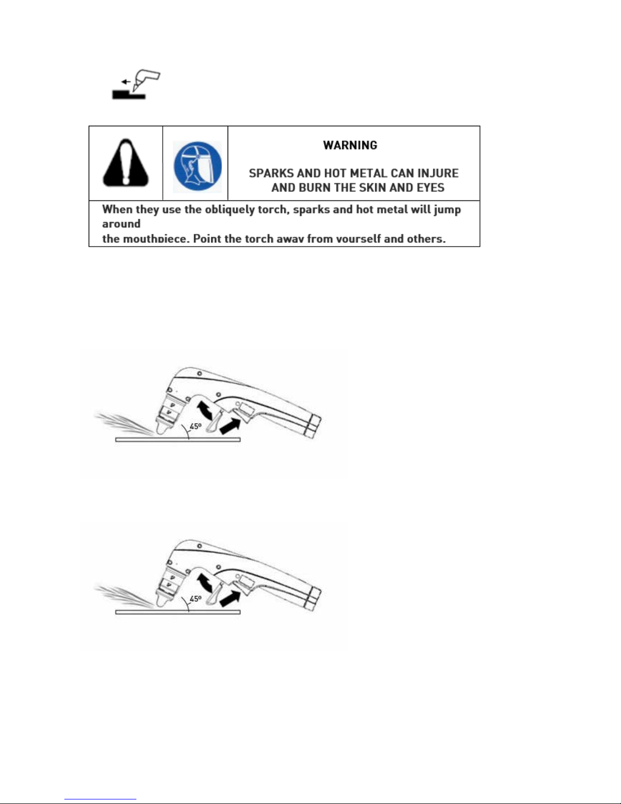
Piercings
Hold the gun so that the nozzle is within 3 mm of the piece before firing.
Trigger the torch obliquely to the piece, then
turn to the vertical position.
When sparks out the piece below, it indicates
that the arc has passed through the material.
After the pierce, proceed to court.
User manual 44
Gouging
Hold the gun so that the nozzle is within 1.5 mm of the piece before firing.
Hold the torch at an angle of 45 ° to
the work piece. Squeeze the trigger
to get a pilot arc. Transfer the plasma
arc to the work piece.
Maintain an approximately 45 ° angle,
of the work piece.
Lean into the slot.
NOTE: A shield is available for heat
for additional hand protection or the
torch.

User manual 45
Mechanized unshielded consumables for 45 Amps
Mild steel
Stainless steel
Aluminum
* You can perform thicknesses up to 32 mm. If the CNC software and system control torch
height up provisionally allow the torch to pass over the pond scum that may form in the piercing.
CUTTING CHART
User manual 46
Mechanized unshielded consumables for 65 Amps
Mild steel
Stainless steel
Aluminum

User manual 47
Mechanized unshielded consumables for 85 Amps
Mild steel
Stainless steel
Aluminum

User manual 48
Mechanized unshielded consumables for 105 Amps
Mild steel
Stainless steel
Aluminum

User manual 49
Mechanized unshielded consumables for 125 Amps
Mild steel
Stainless steel
Aluminum

User manual 50
MAINTENANCE
WARNING
ELECTRIC SHOCK CAN KILL THE
Disconnect electrical power before servicing. A
trained technician should do any work that requires removing the cover of the power supply.
Each time it is used Check the gas pressure. Ensure that consumables are
installed properly and are not
worn.
Each week
Examine and check the safety switch for the cap: note the
red fault light and yellow light of the holding cap of the
torch, which illuminate when the cap is loose.
Every 3 months Replace damage labels Check pressure hose, filter
element, and connections for
leaks that.
Replace the cable or the
mains plug if they were
damaged.
Replace the torch cable if
damaged.
Replace damage labels
Every 6 months Clean the inside of the power
source with compressed air
or vacuuming.
Routine maintenance

User manual 51
Consumables inspection

User manual 52
Replace the gas filter element
Disconnect electrical power and gas supply. Remove the filter bowl.
A. Take out the metallic cover of the machine.
B. To release pull the black tab down and hold it.
C. Turn the filter bowl until it releases.
D. Pull the filter bowl down to remove.
Note: Do not discard the O-ring.
Remove the filter element from the filter housing.
Note: Do not allow the filter element turn when loosening the screw.
1.
2.
3. Install the filter bowl.
A. Slide the filter bowl on the filter element.
B. Align the marks on the filter bowl and filter body.
C. Turn the filter bowl until it clicks and locks into place.

User manual 53
Controls and indicators
Lighting indicators
Normal and bevel cutting.
Discontinuous material cutting (grid).
Gouging or remove welding.
Security indicator cap holding the torch.
On indicator signal START.
Indicator transferred arc and start cutting
(motion).

User manual 54
Solution to basic problems
Problems Cause/solution
Turn ON the main switch ON / OFF and the
control do not light
The line cord is not plugged into the socket.
Connect the line cord into the socket.
The power switch is not turned on or there is
no power switch on the power box.
Turn on power at the central panel or switch
box power.
Note: The fan turns ON and turns OFF
automatically. It is possible the fan is not
operating when the power is turned ON.
1. 1.1
1.2
1.3
2. On the display appears ”PHA”. 2.1 On of the three phases supply is not
connected. Check the installation by an
electrician.
3. The display leds, are flashing. 3.1 The voltage of one the phases, is very low.
Check the installation by an electrician.
4. On the display appears “HOT” message. 4.1 One of the internal switches thermostat
has ed due to overheating or low operation under extreme temperature.
Let the plasma generator on and allow
the fan to cool the generator (which is
over heated). Move the power source to a
colder place (extreme cold).
5. On the display appears “SEC”. 5.1 Check the pins or in the back side of the torch
(pins number 1-2-9) some of them could be
broken from outside or disconnected from its
place from inside of the central connector.
Check in the female central connector if
some of the pins (1-2-9) its been pushed back
into the power source and it is not touching
its corresponding male pin from the torch
side.

User manual 55
Problems Cause/solution
The arc does not jump to the part on which
you are working.
Work clamp is not connected to the work
piece, the work clamp is broken, or there
is a wrong connection inside the mass
cable. Connect or repair the mass
clamp/cable.
Work clamp does not make good contact
metal.
Clean the area where the work piece.
Connect the work piece.
The torch is too far from the piece.
Bring the torch to the workpiece and start
again.
6. 6.1
6.2
6.3
7. The arc goes out, but comes back on when
the gun trigger is pulled.
7.1 Consumable parts are worn or damaged.
Check and replace consumable parts if
they are need. Check the consumables in
this section.
The gas pressure is incorrect.
Adjust the gas pressure. See Setting and
check gas pressure, section 4.
Check that the gas pressure in the power
supply is not less than 6.0 bar with a flow
of 200 l / min
The internal filter gas element is
contaminated.
Change the element - See Change the
filter element, in this section.
7.2
7.3
8. The arc sputters and hisses. 8.1 The gas filter element out of the power
source is contaminated.
Replace the filter element.
There is water in the air line.
Drain the filter bowl. See additional
filtration gas in section 3.
Consumables worn or improperly
installed.
Inspect the consumables. Replace if
necessary.
8.2
8.3
9. The cut quality is not good. 9.1 The consumables are worn or not
properly used.
See Inspection of consumables in this
section.
See Operation Torch, section 4.

User manual 56
Solution to basic problems
Problems Cause/solution
On the display appears “VOO” message. The plasma arc is extinguished for lack of
material to be cut.
10. 10.1
11. 11.1
On the display appears“TOR” message.
Consumables are stuck or worn.
Turn the power OFF and check
consumables assembly line.
Technical questions
If you cannot solve a problem by following this basic troubleshooting guide or if you need further
assistance:
1. Call your dealer or authorized service center.
2. Call the nearest office listed at the beginning of this manual.
3. Seek the service manual for the CUT 65 - 125, where you will find wiring diagram,
troubleshooting and high level information lists more pieces.

User manual 57
Electric system circuits draw
User manual 58
PARTS
Configuration of the torch consumables

User manual 59
Configuration of the torch consumables (continuation)
User manual 60
DECLARATION OF CONFORMITY
DOC TW CUT 65
User manual 61
DOC TW CUT 85

User manual 62
DOC TW CUT 105

User manual 63
DOC TW CUT 125

User manual 64
MANUFACTOR AND DISTRIBUTOR INFORMATION
Weldcut-Punto Plasma, S.L.
Pol. Ind. Can Canals Sector Sur-Oeste
C/Tagomago 3
08192 Sant Quirze del Vallés
(Barcelona) ESPAÑA
Tel.: 937842918
Fax: 937315226
http://www.tecnomec.es
tecnomec@ballero.com
Technical data subject to change without notice.
No liability for printing errors.
Text and Illustrations are protected by copyright.
TEAMWELDER Germany GmbH
Tel +49 2623 9276-400
Fax: +49 2623 9276-444
info@teamwelder.com
Sälzerstraße 20a
56235 Ransbach-Baumbach
Germany
 Loading...