

Page 1
TeCom-XP
TeCom-XP
Bedienungsanleitung
Deutsch
Instruction Manual
English
Manual de usuario
Español
Manuale d’ uso
Italiano
Page 2
3
Deutsch
2
1
9
5
7
6
8
4
3
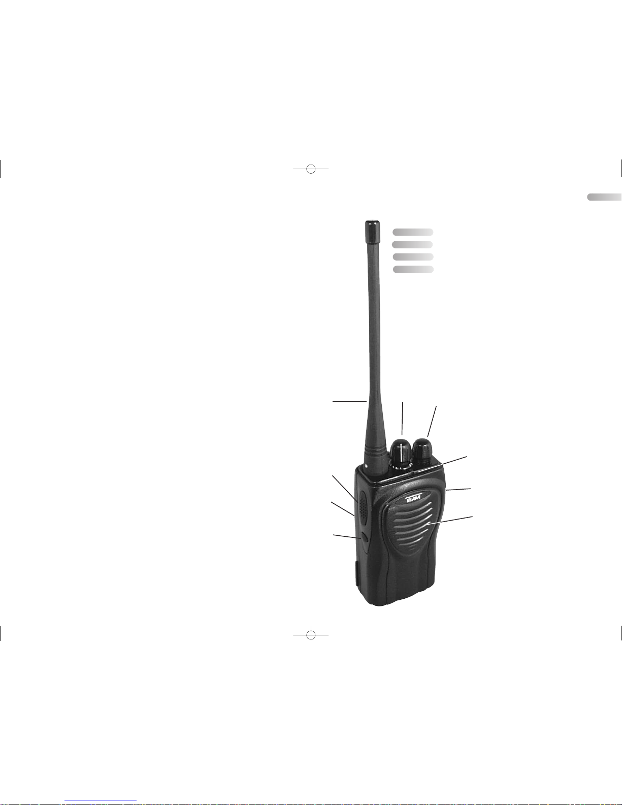
1) Antenne
2) Kontrolllampe
3) Kanaldrehwahlschalter,
16stufig [1 - 15, S]
4) Lautstärkeregler, kombiniert
mit Ein-/Aus-Schalter [OFF]
5) PTT-Taste
6) Monitor-Taste
7) Doppelbuchse Ø 2,5/3,5 mm
für Zusatzgeräte
8) Lautsprecher
9) Akkumulator 6 V / 1300 mAh
1) Antenna
2) Control lamp
3) Rotary channel selector,
16 steps [1 - 15, S]
4) Volume control with ON/OFF
switch [OFF]
5) PTT key
6) Monitor key
7) Double socket Ø 2.5/3.5 mm
for auxiliaries
8) Loudspeaker
9) Accumulator 6 V / 1300 mAh
Bedienungsanleitung Seite3 - 13
Instruction Manual Page 14 - 27
Manual de usuario Pagina 30 - 42
Manuale d’uso Pagina 46 - 58
Deutsch
English
Español
Italiano
TEAM TeCom-XP
Manual_4.qxp 13.01.2007 18:06 Seite 3
Page 3

Table of Contents
Page
Controls and Connectors 3
Preface 16
Setting Up the TEAM TeCom-XP 16 - 17
Mounting of the Accumulator 17
Detaching the Accumlator 17
Mounting and Detaching the Belt Clip 17
Operation of the TEAM TeCom-XP 17 - 20
1) Turning the Unit On / Off 17
2) Volume Level Adjustment 18
3) Channel Selection 18
4) Transmission 18
5) Reception 18 - 19
6) Sockets for External Speaker-Microphone 19
7) Charging of the Accumulator 19 - 20
8) Accumlator Alert Indication 20
9) Energy Saving Function 20
Scan Function of the TEAM TeCom-XP 20 - 21
1) Activation of the Scan Function 20
2) Deactivation of the Scan Function 20
3) Method of Working of the Scan Function 21
Auxiliary Functions of the TEAM TECom-XP 21 - 22
1) Transmit Time Limiter 21
2) Busy Channel Lockout Function 21
3) Additional Mute Function 22
General 23
1) Safety 23
2) Service 23
3) Conformity 23
4) Programmed Channels 24
5) Programmed Functions 24
6) Programmed Functions 24
7) Technical Data 25
8) DQT & CTCSS Codes 26
Optional
Accessories
English
Manual_4.qxp 13.01.2007 18:06 Seite 15
Page 4
English English
Mounting of the accumulator
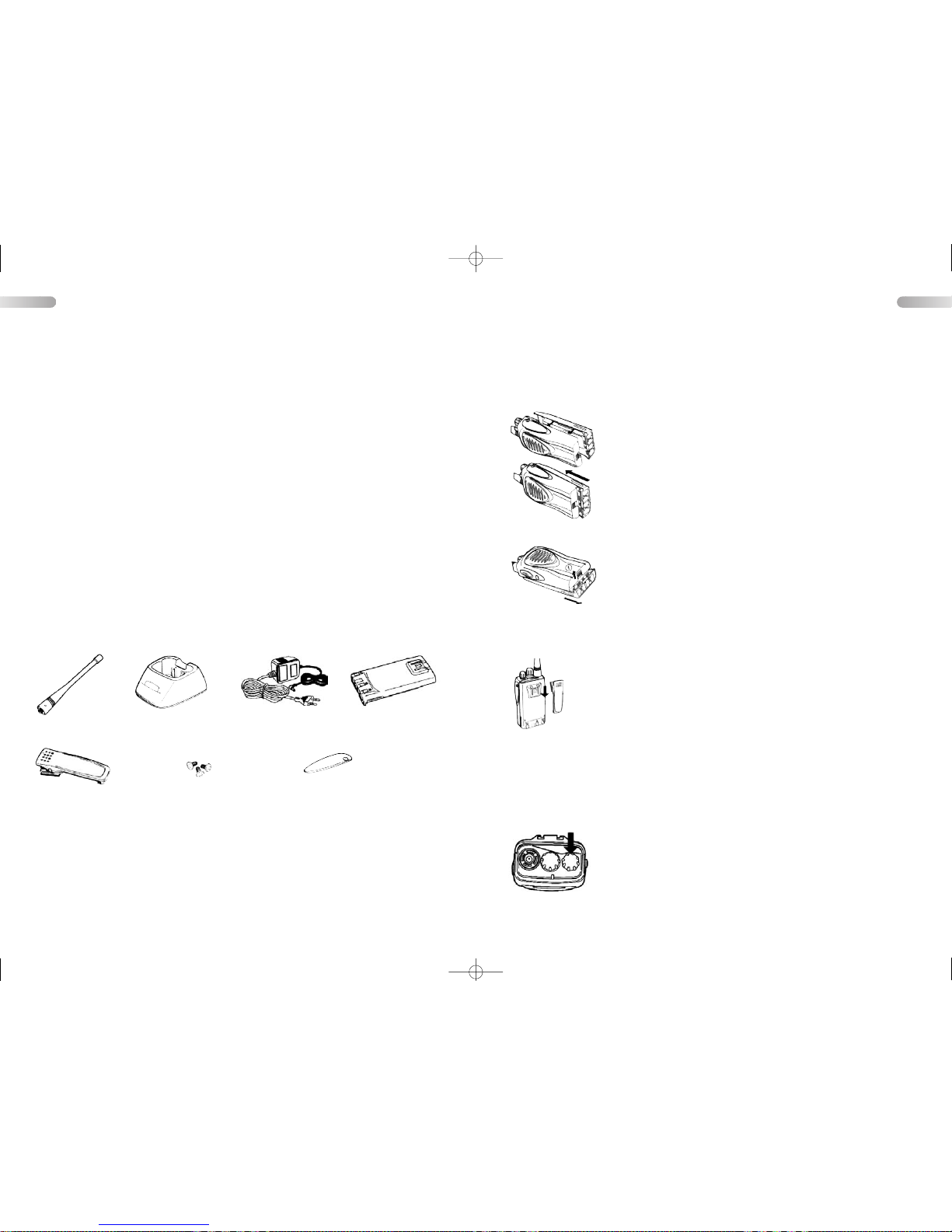
At first turn the rear panel towards you. Place the accumulator
( 9 ) in that way on the unit's rear panel that the 4 slip planes of
the unit grip into the corresponding guiding slots of the accumulator, and that the accumulator's charging contacts show into the
direction of the unit's base. Then push the accumulator under
simultaneous slight pressure on its back into the direction of the
unit's top side, until the latch on the unit's base clicks into place.
Now the unit is ready for radio operation.
If you want to use the unit as a professional transceiver, you have to contact
your local telecommunication authorities. You may be required to pay costs of
registrations and annual fees for every unit and for every frequency. If your
application is passed, you can go to your dealer and let him set your TeCom-XP
to the permitted frequency(ies) and adjustments.
Setting Up the TEAM TeCom-XP
Unpack carefully your UHF radio TeCom-XP. Please check whether the supplied
material matches with the items listed below. In case of loss or damage of a part
contact your carrier at once.
Antenna Charging Mould Mains Adapter Accumulator
Belt Clip Screws Protection cover for double socket
This transceiver is a heavy duty PMR radio, which can be optionally modified by
your dealer also into a professional transceiver. In this unit only the channels 1 - 8
are already factory-preset to the PMR channels, i.e. the number of the rotary
channel selector position corresponds with the actual PMR channel. The positions 9 - 16 are free according to the factory setting. The TX output power on the
PMR channels is reduced to 500 mW in the radiated field according to the European regulation. See in the chapter "technical data" for the table of the PMR
channel numbers together with the corresponding frequencies. When the unit
remains in pure PMR operation, it is free of charge and registration in most
European countries.
( 6 V / 1300 mAh )
Preface
The TeCom-XP is available in 2 Versions:
TeCom-XP (PMR) - item no. PR8017
This PMR handheld transceiver can be used without license and registration in the
countries according to the Declaration of Conformity that is included in the scope
of delivery. The radio is equipped with 8 PMR channels ( 446 MHz ) with the maximal permitted TX power of 500 mW. Increasing of the TX power is not permitted
and will cause the expiration of the operation permit. The antenna of the radio is
fixed.
TeCom-XP (COM) - item no. PR8019
The operation of this commercial handheld transceiver requires a license and fees
apply. It can only be operated according to the Declaration of Conformity that is
included in the sope of delivery. The radio can only be operated on authorised,
assigned frequencies in the range between 450 - 470 MHz with the maximal
assigned output power. With the commercial version, the antenna is removable.
1716
Detaching the accumulator
Turn again the unit's rear panel towards you. To release the
accumulator from the unit you have to pull the latch on the unit's
base with your finger towards the unit's front panel, while pushing simultaneously the accumulator towards the unit's base.
After the accumulator is slid out of the unit's slip planes you can
take it off.
Mounting and removing the belt clip
Turn the rear unit's panel with mounted accumulator towards you.
Mounting: Insert the springy support of the belt clip from above into the
corresponding guide on the back of the accumulator. Push the belt clip
into the direction of the unit's base until the belt clip's latch clicks into
place.
Detaching: The latch of the belt clip is located on the accumulator's
back near the top side. Pull the latch with your fingernail away from the accumulator's back and push simultaneously the belt clip towards the unit's top side.
After the belt clip is slid out of its guide you can take it off.
Operation of the TEAM TeCom-XP
1) Turning the unit On/Off
To turn on the unit rotate the volume control with ON/OFF switch
[OFF] ( 4 ) from its rest position clockwise until you hear a clikking sound. 1.5 seconds later a short beep tone will be heard
from the loudspeaker ( 8 ), which indicates that the unit is in
reception mode. To switch off the unit rotate the volume control
with ON/OFF switch [OFF] ( 4 ) counterclockwise to the final stop [OFF] until you
hear a clicking sound. This indicates that the unit is switched off now.
Manual_4.qxp 13.01.2007 18:06 Seite 17
Page 5
English English
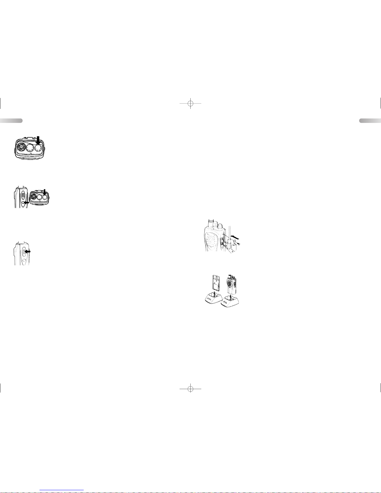
6) Sockets for External Speaker-Microphone
Behind the screw-fixed cover on top of the unit's right side you
can find two jack sockets for stereo plugs Ø 2,5/3,5 mm
[SPK/MIC] ( 7 ). They serve for the connection of a speakermicrophone with PTT function or for a separate microphone or
a separate speaker. The upper socket is for the speaker and the
lower socket is for the microphone. The internal speaker and/or
the internal microphone will be switched off, if the socket for the
corresponding external accessory is in use.
7) Charging of the Accumulator
The accumulator is not charged in the factory. Therefore it must
be charged before it is used the first time.
Insert the DC connector of the power cord coming from the
adaptor into the socket on the rear of the charging mould. Then
connect the adaptor with a wall outlet ( 230 V, 50 Hz ).
Now insert the transceiver with mounted accumulator or only
the accumulator itself into the charging mould. The front panel
of the unit must show into the direction of the LED indicator of the charging
mould, or the charging contacts of the accumulator to the rear.
The LED indicator on the charging mould indicates the status of the charging
process:
RED - constant light : Charging is in process
RED - blinking : Charging mode has been activated recently
GREEN - constant light : Charging is completed
GREEN - blinking : Discharging is in process; voltage is is below 6 V .
Once the voltage is below 4.8 V, the charging
process starts and the LED blinks red.
With this rapid charger, the charging process is completed within 2 - 3 hours.
simultaneously to light up green and turn the loudspeaker on. This indicates that
the channel is occupied. Your dealer can also adjust the squelch threshold. If
you are using also the additional muting function the codes of your unit and the
one of the counter station have to match also before the squelch turns the loudspeaker on.
The squelch function can be disabled by the user to hear also weak stations
which are not strong enough for the squelch to turn the loudspeaker on, and under the regime of the additional muting function - those stations which use a
non corresponding code ( monitor function ).
Depress the monitor key ( 6 ). Now the noise suppression is shut off and the
control lamp lights simultaneously up green. If there is no station on the actual
channel you hear a noise in the speaker. To reactivate the squelch depress the
monitor key ( 6 ) again or change the channel. Thus the squelch works again.
The monitor key function can also be changed to momentary operation by your
dealer. For further information see point 3 of the chapter "Auxiliary functions of
the TeCom-XP".
2) Volume level adjustment
If a radio operator sends a message on the actual channel, you can
hear it in the incorporated loudspeaker ( 8 ). If the actual channel is
free, the loudspeaker will be silent. In this case you can produce a
strong noise in the loudspeaker by pressing the monitor key ( 6 ).
Adjust the volume control ( 4 ) to a comfortable listening level. Turning the control clockwise will increase the volume level and turning it counterclockwise will reduce the volume level.
3) Channel selection
The TEAM TeCom-XP has maximal 16 channels available. To
select another channel turn the rotary channel selector [1-15, S] (
3 ). According to the programming of the channels, which can be
factory made or made by your dealer, the unit will call up those
transmit and reception frequencies which correspond to the actual
position 1 - 15 ( S ) of the rotary channel selector.
Note: If the rotary channel selector is set to a not programmed position, you will
hear a continuous warning tone in the loudspeaker.
4) Transmission
Be sure that the antenna ( 1 ) is mounted. Never transmit without connected
antenna. Then check activity on the actual channel. Do not send if someone
talks on the actual channel. Only if the loudspeaker is silent and the control
lamp ( 2 ) is dark, the channel is free. Press also the monitor key ( 6 ). There
must be a noise if the channel is not occupied.
To transmit depress and hold the PTT key ( 5 ). During transmission the control
lamp ( 2 ) lights up red and the rotary channel selector is disabled. Hold the unit
upright. The sensitivity of the built-in microphone is set for speaking at a
distance of 2 inches. Speaking too loud will cause distortions and makes the
signal difficult to understand. On completion of the transmission release the PTT
key and the set will return to receive mode.
Note: Radio operation is only possible with the counter operator at coinciding
channels. If you are using also the additional muting function, the corresponding
codes of your unit and the counter station must also coincide. For further information to the additional muting function see point 3 of the chapter "Auxiliary
functions of the TeCom-XP".
5) Reception
After being switched on, the unit is always in receiving mode, as long as it is not
transmitting. When it does not find any signal on the actual channel, it would
produce a disturbing noise in the loudspeaker ( 8 ). For this end the unit is
equipped with a built-in noise suppression circuit ( squelch ) that mutes the
receiver if there is no station on the actual channel. If there is any incoming
signal of a certain strength, the squelch will cause the control lamp ( 2 )
1918
Manual_4.qxp 13.01.2007 18:06 Seite 19
Page 6

English English
3) Method of Working of the Scan Function
When the scan function has found a signal on a channel which is programmed
with the additional muting function, it will test whether the code of the signal matches to the one which is programmed on the actual channel. In case of mismatch the scan function pauses only for a short time on that channel. But the
squelch will not turn the loudspeaker on. The green glowing of the control lamp
indicates that the unit has recognised internally the occupation of this channel.
For further information to the additional muting function see point 3 of the chapter "Auxiliary functions of the TeCom-XP".
When pressing the PTT key while the scan function is stepping through the
channels the unit transmits on the transmit frequency of channel 16. When the
pressing of the PTT key occurs while the scan function is resting on a channel,
the unit transmits on the transmit frequency of this channel.
Once a channel is selected for transmit mode, you can send your entire message on this channel. After you have released the PTTkey the unit will still stay
for a dwell time of 10 seconds on this channel, before the channel searching is
restarted again.
Auxiliary functions of the TEAM TeCom-XP
These functions must be installed into your transceiver by your dealer, before you
can use them. In the description below it is assumed that the functions are active.
Ask your dealer for more details.
1) Transmit Time Limiter
The transmit time limiter ( = time-out-timer ) has the effect of limiting the maximum time for continuous transmitting on a channel. This transmit duration limit
can be adjusted in steps between 0.5 and 5 minutes by your dealer. If the transmit time exceeds the actual transmit duration limit during your message, the
transmitter will shut off automatically, and you will hear a warning tone in the
speaker. To stop the warning tone and to reactivate the transmitter you have to
release briefly the PTT key and to depress it again.
2) Busy Channel Lockout Function
The lockout function for busy channels has the effect to prevent the unit from
interfering with other stations. If there is a station on the actual channel at the
moment when you press the PTT key, the transmitter will not be switched on. In
this situation you will only hear a warning tone in the speaker. When you release
the PTT key the warning tone will be stopped and the set will revert to receiving
mode. You can only send if there is no station on the actual channel at the
moment when you press the PTT key.
ATTENTION:
> During charging process, do not use the TeCom-XP for radio communication.
The radio should be turned off while charging.
> After charging is finished, remove the radio and the rechargeable battery from
the charger and unplug the AC/DC adapter of the charger from the wall socket.
> Do not attempt to charge alkaline cells or any other accumulator than the sup-
plied one with this charger.
8) Accumulator Alert Indication
The unit is equipped with an accumulator level monitoring circuit which alerts you,
when the stored energy is nearly completely used up. If the accumulator voltage
drops below 5.5 V while transmitting, the control lamp ( 2 ) starts to flash red. But
the transmitter is still working. If you keep on transmitting and the accumulator voltage drops below 5.3 V, you will hear a warning tone in the speaker and the transmitter will switch itself off. After releasing the PTT key and pressing it once again,
the unit will transmit again but only for a short time. Now it is time to recharge the
accumulator. If the unit is in receiving mode, the accumulator voltage can drop
below 3.5 V , until the control lamp ( 2 ) st arts to flash red every 5 seconds, accompanied by a short warning tone in the speaker. At 3.1 V the unit switches itself off.
9) Energy saving function
The unit is equipped with an energy saving function. This function is factory set
in your unit. This function works only in receive mode. It reduces the current
consumption when no signal is detected on the actual channel and the rotary
channel selector is not turned for at least 10 seconds. If you do not use the unit
for a longer period of time, you should switch it off.
Scan function of the TEAM TeCom-XP
The scan function must be installed into your transceiver by your dealer, before you
can use it. If it is not installed, there is another channel available on position [S] ( =
16 ) of the rotary channel selector. In the description below it is assumed that the
scan function is active. Ask your dealer for more details.
1) Activation of the Scan Function
When you turn the rotary channel selector on position [S] ( = 16 ) the unit runs
through all channels which your dealer has programmed into the unit. If there is
a radio operator signal on one channel which is capable to open the squelch,
the scan function will pause on that channel until it is free again. You can hear
the partner station. 5 seconds after that station has finished its message the
scan function will restart running through the channels.
2) Deactivation of the Scan Function
When you turn the rotary channel selector on a position between 1 and 15 the
scan function is not active.
2120
Manual_4.qxp 13.01.2007 18:06 Seite 21
Page 7

English English
General
1) Safety
The unit radiates RF energy in transmitting mode. To reduce the exposure to the
lowest possible value and to benefit the most of the set's features, keep the following in mind:
In transmission mode, keep the unit in a vertical position at a distance of 2
inches away from your face. Keep the antenna at a distance of at least 3 inch
away from your head and your body. If you are carrying the unit at the body,
make sure that the antenna keeps a minimum distance of 3 inch to your body
in transmit mode.
2) Service
The condition of the accumulator must be tested from time to time. If the accumulator is weak a short time after complete charge, it should be removed from
the set. It can leak and damage the device. Replace it by a new one.
Worn out accumulators do not belong into the waste bin, but must be returned
to a suitable collecting depot or to a special dealer, for the sake of the environment.
There are no user-adjustable or user-serviceable parts inside the radio. The
casing must not be opened. Independent repairs or adjustments must not be
carried out, since each modification or unauthorised intervention will immediately cancel all and any guarantee or repair claims, they are also likely to result
in non-conformity to ETS/EN regulations which will render the set to become
illegal.
In the event a defect becoming apparent, contact a properly equipped and authorised TEAM dealer or TEAM directly.
3) Conformity
The transceiver TEAM TeCom-XP complies with the rules of the European
Directive R&TTE and meets the European Telecommunication Standards EN
300 296, EN 300 086, EN 301 489-1/-5 and EN 60065.
3) Additional Mute Function
The unit is also equipped with a possibility to suppress messages of unwanted
operators on the actual channel while the message of the partner station
remains audible. To identify the wanted radio messages there are two methods
available: CTCSS and DQT.
CTCSS method ( = Continuous Tone Coded Squelch System ): The wanted
radio message must contain a certain inaudible tone, which the CTCSS detecting circuit of the receiving unit recognises and which can take the muting function out of service. In transmit mode the unit adds to its voice signal also a certain inaudible tone which will be recognised by the CTCSS detecting circuit of
the counter station's receiver to open its additional muting device.
DQT method ( Digital Quiet Talk ): The digital pulse detecting circuit of the receiving unit checks if the received signal contains any returning sequence of digital pulses. If it has identified sequences of digital pulses of a certain code in the
wanted message, the muting device lets the radio message pass. In case of
sending DQT coded messages the unit adds to its voice signal also sequences
of digital pulses of the a certain code, too. These pulses will be recognised by
the digital pulse detecting circuit of the counter station's receiver, which gives an
order to the muting device to let the radio message pass to the speaker.
Please take into account that other radio operators, who are not equipped with
a CTCSS or DQT coding/encoding device, or who don't use it, can hear all your
conversation if they are working on the same channel like you and your counter operator. The same applies to users of the TeCom-XP if the CTCSS and the
DQT function is out of service on that channel.
Your dealer can install for each channel separately the CTCSS or DQT operation. It is also possible to set at the same channel different operation types for
receive and transmit mode.
If the CTCSS or DQT operation is installed in receiving mode on the actual
channel, and if there is a radio operator on this channel who uses either no
CTCSS or DQT operation or a not according one, you will see only the control
lamp ( 2 ) lighting up green, but the speaker will be silent. This shows you that
the channel is occupied and that you should not transmit on this channel for not
disturbing the other station.
The CTCSS method allows your dealer to select one of 50 different inaudible
tones to encrypt your messages between you and the wanted radio operator. If
you use the DQT method your dealer will have 210 different digital codes to
encrypt your messages between you and the wanted radio operator.
The monitor key stops besides the noise suppression also a possible CTCSS or
DQT operation in the receiver. The monitor key function can be activated in two
ways by your dealer:
1. A brief pressure on the key can switch the noise suppression together with
a possible CTCSS or DQT operation on and off.
2. The noise suppression together with a possible CTCSS or DQT operation is
only off while the monitor key is pressed.
2322
Manual_4.qxp 13.01.2007 18:06 Seite 23
Page 8
2524
6) Technical Data
PMR version
Channel number - Frequency [ MHz ]
1 - 446.00625 5 - 446.05625
2 - 446.01875 6 - 446.06875
3 - 446.03125 7 - 446.08125
4 - 446.04375 8 - 446.09375
Channel spacing : 12.5 kHz
Radiated TX output power : 500 mW
Modulation type : FM
Deviation : max. 2,5 kHz ( narrow )
RX sensitivity : + 14 dBμV/m ( narrow )
Audio output power : 0.39 W at 8 Ω at 10 % THD
Supply voltage : 5.4 - 6.5 V
Current consumption : TX: 660 mA
RX at 0,39 W on 8 Ω: 170 mA;
RX silent: 55 mA
RX with power save function: 25 mA
Professional version
Frequency range : 450 MHz - 470 MHz
Frequency step size : 6.25 kHz; 5 kHz
Channel separation : narrow: 12.5 kHz / wide: 25 kHz
TX output power : max. 4 W
Modulation type : FM
Deviation : narrow: 2.5 kHz / wide: 5 kHz
RX sensitivity : narrow: +14 dBμV/m / wide: +8 dBμV/m
Audio output power : 0.39 W at 8 Ω on 10 % THD
Supply voltage : 5.4 - 6.5 V
Current consumption : TX ( Low ): 660 mA
TX ( High ): 1.8 A
RX as above
Dimsions ( cabinet ) : W/H/D: 55 x 102 x 37 mm
Weight with Batteries
and antenna : 278 g
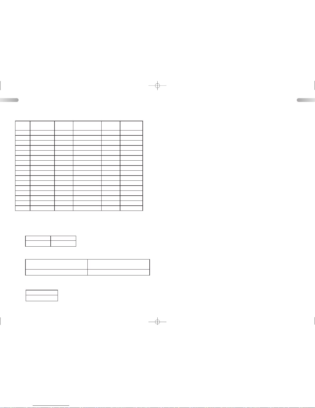
4) Programmed channels
5) Programmed functions
Insert below the functions that your dealer has programmed into your transceiver.
Channel scanning
Function of the monitor key
Transmit time-out-timer
Channel TX Frequency
(MHz)
EncryptionTXReception Fre-
quency (MHz)
DecryptionRXBandwidth
wide/narrow
1 446.00625 446.00625 N
2 446.01875 446.01875 N
3 446.03125 446.03125 N
4 446.04375 446.04375 N
5 446.05625 446.05625 N
6 446.06875 446.06875 N
7 446.08125 446.08125 N
8 446.09375 446.09375 N
9
10
11
12
13
14
15
16
Activated Deactivated
Duration [ min ]
Switching on and off noise squelch,
CTCSS and DQT in toggle mode
Stopping noise squelch, CTCSS
and DQT only during pressure
English English
Manual_4.qxp 13.01.2007 18:07 Seite 25
Page 9
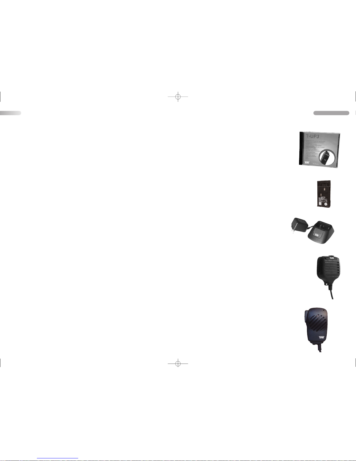
Optionales Zubehör / Optional Accessories
DM-3608
Elegantes Lautsprechermikrofon mit Spiralkabel und
separater Ohrhörerbuchse passend für EP-35M /
Speakermicrophone with spiral cable and separate
earphone-jack for EP-35M
Art.-Nr. / item no. PR2103
DM-3208
Robustes Lautsprechermikrofon mit Spiralkabel und separater
Ohrhörerbuchse passend für EP-25M /
Speakermicrophone with spiral cable and separate earphonejack for EP-25M
Art.-Nr. / item no. PR2068
APP-TeCom-XP
Aufladbare Akku-Pack / rechargeable battery pack
( 1300 mAh / 6.3 V )
Art.-Nr. / item no. PR2132
SLG-TeCom-XP - Intelligent
Standladegerät mit Netzadapter / desktop charger with power supply
Art.-Nr. / item no. PR2130
T-UP3
PC-Programmiersoftware + Programmieradapterkabel
( ab Windows 98 ) Serial-Port COM /
PC-Programming Software ( Windows 98 and up f) +
Adapter Cable for Serial-Port COM
Art.-Nr. / item no. PR2091
2726
Deutsch / English
Code Code Code Code Code Code
D023N D1
16N D225N D325N D452N D627N
D025N D122N D226N D331N D454N D631N
D026N D125N D243N D332N D455N D632N
D031N D131N D244N D343N D462N D645N
D032N D132N D245N D346N D464N D654N
D036N D134N D246N D351N D465N D662N
D043N D143N D251N D356N D466N D664N
D047N D145N D252N D364N D503N D703N
D051N D152N D255N D365N D506N D712N
D053N D155N D261N D371N D516N D723N
D054N D156N D263N D411N D523N D731N
D065N D162N D265N D412N D526N D732N
D071N D165N D266N D413N D532N D734N
D072N D172N D271N D423N D546N D743N
D073N D174N D274N D431N D565N D754N
D074N D205N D306N D432N D606N
D114N D212N D311N D445N D612N
D115N D223N D315N D446N D624N
D023I D116I D225I D325I D452I D627I
D025I D122I D226I D331I D454I D631I
D026I D125I D243I D332I D455I D632I
D031I D131I D244I D343I D462I D645I
D032I D132I D245I D346I D464I D654I
D036I D134I D246I D351I D465I D662I
D043I D143I D251I D356I D466I D664I
D047I D145I D252I D364I D503I D703I
D051I D152I D255I D365I D506I D712I
D053I D155I D261I D371I D516I D723I
D054I D156I D263I D411I D523I D731I
D065I D162I D265I D412I D526I D732I
D071I D165I D266I D413I D532I D734I
D072I D172I D271I D423I D546I D743I
D073I D174I D274I D431I D565I D754I
D074I D205I D306I D432I D606I
D114I D212I D311I D445I D612I
D115I D223I D315I D446I D624I
CTCSS Kodenummer - Frequenz [ Hz ] / Code No. - Frequency
7) DQT-Codes
37 - 189,9
38 - 192,8
39 - 196,6
40 - 199,5
41 - 203,5
42 - 206,5
43 - 210,7
44 - 218,1
45 - 225,7
28 - 162,2
29 - 165,5
30 - 167,9
31 - 171,3
32 - 173,8
33 - 177,3
34 - 179,9
35 - 183,5
36 - 186,2
10 - 91,5
11 - 94,8
12 - 97,4
13 - 100,0
14 - 103,5
15 - 107,2
16 - 110,9
17 - 114,8
18 - 118,8
1 - 67,0
2 - 69,3
3 - 71,9
4 - 74,4
5 - 77,0
6 - 79,7
7 - 82,5
8 - 85,4
9 - 88,5
19 - 123,0
20 - 127,3
21 - 131,8
22 - 136,5
23 - 141,3
24 - 146,2
25 - 151,4
26 - 156,7
27 - 159,8
46 - 229,1
47 - 233,6
48 - 241,8
49 - 250,3
50 - 254,1
English
Manual_4.qxp 13.01.2007 18:07 Seite 27
Page 10
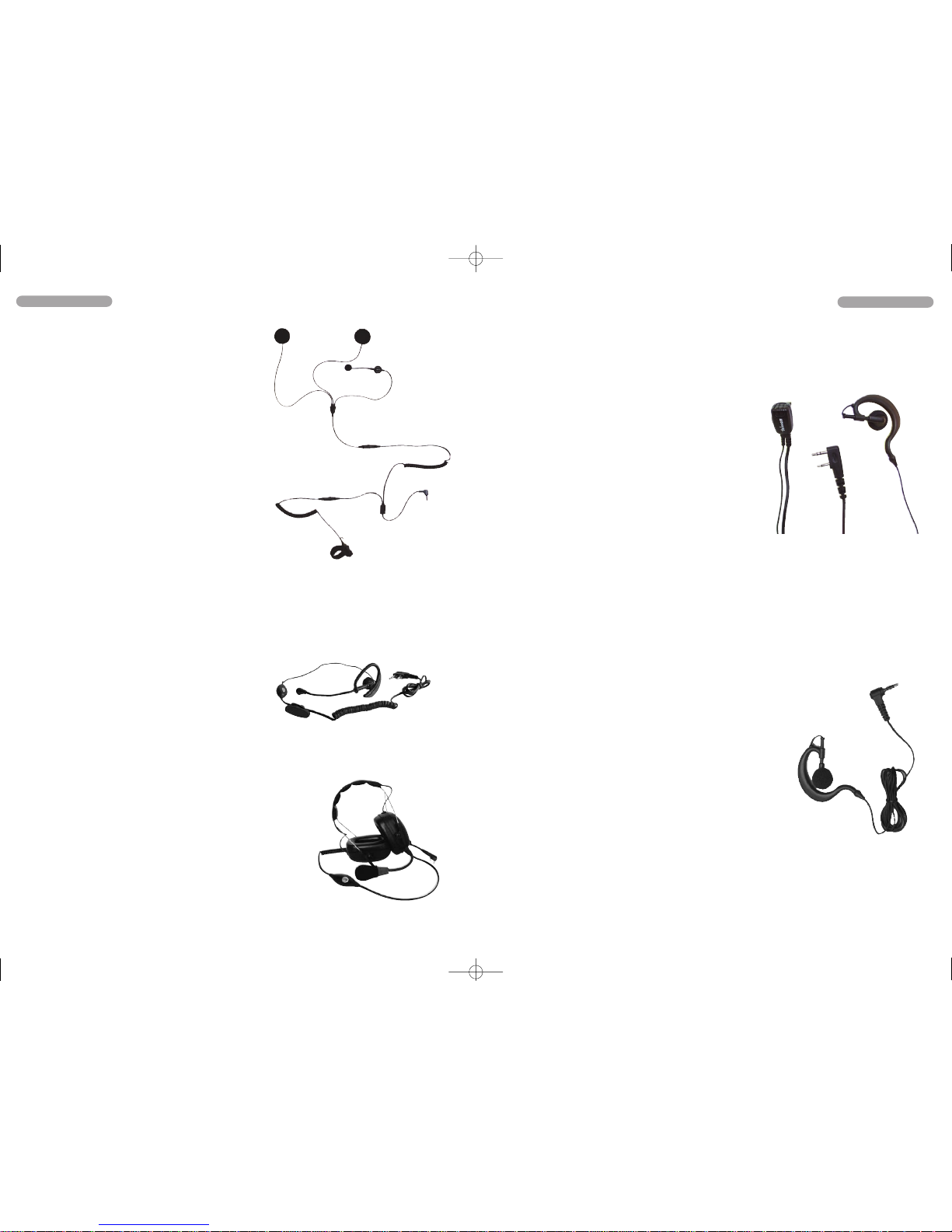
PY-29K
Ohrhörer-Ansteckmikrofon mit Ohrbügel und
efestigungsclip /
Earphone with clip-on microphone
Art.-Nr. / item no. PR2073
PY-29AUK
Ohrhörer mit flexiblem Ohrbügel, Ansteckmikrofon mit
PTT-Taster
Earphone with flexible earpiece, clip-on-microphone
with PTT-switch
Kenwood, TEAM PT-2208S, PT-3208S, TeCom-XP
Art.-Nr. / item no. PR2083
2928
PT-29MEP
Ohrhörer-Ansteckmikrofon mit Ohrbügel und
efestigungsclip /
Earphone with clip-on microphone
Art.-Nr. / item no. PR2170
PT-29EP
Ohrhörer mit flexiblem Ohrbügel, Ansteckmikrofon mit
PTT-Taster
Earphone with flexible earpiece, clip-on-microphone with PTT-switch
Kenwood, TEAM PT-2208S, PT-3208S, TeCom-XP
Art.-Nr. / item no. PR2169
Deutsch / English
Deutsch / English
RiderPhone-PT
Helmsetgarnitur bestehend aus:
1 x Rüsselmikrofon mit Klettbandverschluss
2 x Flacher Lautsprecher mit
Klettbandbefestigung
1 x Abgesetzer PTT Schalter mit
Klettbandbefestigung
1 x Anschlußkabel mit Kupplung &
1-Pin Anschlußstecker
1 x Ersatz-Klettbandbefestigung
helmet set containing:
1 x boam microphone with velcro tape
2 x flat speaker with velcro tape for helmet
1 x separate PTT-switch for handle bar
1 x connecting cable with coupling and 1-Pin connector
1 x additional velcro fastening kit
Art.-Nr. / item no. PR2078
OEM-PT-3208S
Ohrbügel-Ohrhörer mit Rüsselmikrofon und externen PTT-Schalter /
earphone with boam microphone and
external PTT-switch
Art.-Nr. / item no. PR2067
H&G-418
Heavy Duty Headset
2-Pin 2,5 / 3,5 mm Stereo, 230 Ohm Dyn. Microphone, NNR 26dB, SNR 33dB
PT-2208S / 3208S / 3508 (2) + (3) / TeCom-XP
Art. Nr. / item no. PR2093
Manual_4.qxp 13.01.2007 18:07 Seite 29
Page 11
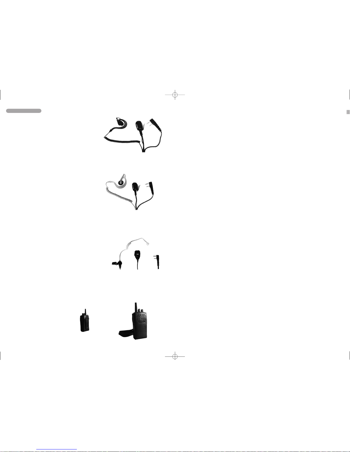
JD-MAT-K
Schlauch-Ohrhörer mit Mikrofon und PTT-Taster /
Earphone with clip-on microphone and PTT-switch
2-Pin 2,5 / 3,5 mm Stereo
für / for PT-2208S / 3208S / TeCom-XP
Art. Nr. / item no. PR2089
Ledertasche / leather bag
TeCom-XP
Art. Nr. / Item No. PR2133
Deutsch / English
Manual_4.qxp 13.01.2007 18:07 Seite 31
Page 12
TEAM TeCom-XP für den Vertrieb und Gebrauch in:
Deutschland, Großbritannien, Italien, Litauen, Niederlande, Öster-
reich, Schweden, Spanien, Schweiz (nur PMR)
TEAM TeCom-XP for sale and use in :
Austria, Germany, Great Britain, Italy,
Lithuania, Netherlands, Spain, Sweden, Switzerland ( only PMR )
TeCom-XP para venta y uso:
España, Austria, Alemania, Inglaterra, Italia, Lituania, Holanda,
Suecia, Suiza (sólo PMR)
TEAM TeCom-XP per vendita ed uso in :
Italia, Espagna, Austria, Germania, Inghilterra, Lituania, Olanda,
Svezia, Svizzera (soltanto PMR)
TEAM Electronic GmbH
Bolongarostrasse 88
D-65929 Frankfurt am Main
Phone ++49 - (0)69 - 3009500
Fax ++49 - (0)69 - 314382
eMail [email protected]
Internet www.team-electronic.de
Alle Rechte und Änderungen sind vorbehalte. Nachdruck
oder Vervielfältigung, auch auszugweise, nur mit schriftlicher Genehmigung der TEAM Electronic GmbH
Rev. Version 01/2007
 Loading...