

Page 1

Bedienungsanleitung
manual
SWR 1180 P
Stehwellen-, Leistungs- &
Feldstärkemessung
for swr , tx-power & field strength
measurement
TEAM Electronic GmbH
Bolongarostraße 88
D-65929 Frankfurt am Main
Germany
fon ++49 - 69 - 300 9 500
fax ++49 - 69 - 31 43 82
web www.team-electronic.de
email team-electronic@t-online.de
Page 2
1. Allgemeines
Die maximale Funkreichweite ist in der Hauptsache abhängig von
dem Antennentyp, Standort der Antenne und der Antennenanpassung. Zur Messung der Antennenanpassung im Frequenzbereich
26,565-27,405 MHz dient dieses Messgerät.
Um einerseits die gesamte vom Funkgerät erzeugte Sendeleistung
in Form von elektromagnetischen Wellen von der Antenne abstrahlen zu können und andererseits dem Empfänger die gesamte von
der Antenne aufgenommene HF-Energie zuzuführen, muss die Antennenanlage optimal an das Antennenkabel bzw. Funkgerät angepasst sein.
Anpassung bedeutet, dass Funkgerät, Stecker, Antennenkabel und
Antenne die gleiche Anschlußimpedanz besitzen. Bei CB-Funkanlagen sind 50 Ohm Impedanz üblich.
Bei Fehlanpassung wird an der entsprechenden Stoßstelle,
(Abweichung der 50 Ohm Anschlussimpedanz) dem Antennenfußpunkt oder den Kabelverbindungen, Sendeleistung reflektiert und
läuft über das Kabel zurück zum Funkgerät. Dadurch entsteht eine
Welligkeit des Spannungsverlaufes auf dem Antennenspeisekabel.
Die reflektierte Leistung ist so minimal wie möglich zu halten, denn
sie kann von der Antenne nicht abgestrahlt werden, was die Funkreichweite reduziert.
Eine absolute Anpassung ist nicht möglich. Mit dem SWR-1180-P
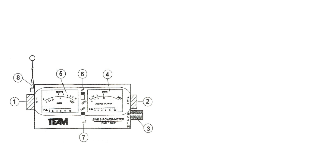
Bedienelemente
1 TX Buchse 2 ANT Buchse
3 CAL Regler 4 SWR Anzeige
5 Sendeleistung Anzeige 6 10 W / 100 W Umschalter
7 REF-FWD Umschalter 8 Antenne
Page 3

Nach der Messung sollte das Messgerät wieder aus der
Antennenleitung entfernt werden, da durch den prinzipiellen
Aufbau der Stehwellenmessgeräte, zu Störungen anderer
Funkdienste kommen kann.
3. Messung des Stehwellenverhältnisses
Nachdem das Messgerät wie unter Punkt 2 beschrieben in das
Antennenkabel eingeschleift wurde, kann mit der eigentlichen
Messung begonnen werden.
> Mit Schiebeschalter (6) [10 W / 100 W] den Messbereich zur
Leistungsmessung wählen. CB-Funkgeräte haben üblicherweise
eine Ausgangsleistung von max. 4 Watt. Auf der linken Anzeige
(5) wird die Sendeleistung angezeigt.
> Schiebeschalter (7) [FWD/REF] in Stellung FWD bringen.
> Nun die Sendetaste am Funkgerät drücken. Der Zeiger des Mess-
instruments (4) sollte nun ausschlagen.
Bei gedrückter Sendetaste den Zeiger des Messinstrumentes,
zur Kalibrierung des Messgerätes, mit dem Regler (3) [CAL] in
Stellung [SET] (Ende der Skala) bringen.
> Den Schalter (7) in Stellung [REF] bringen.
Bei weiterhin gedrückter Sendetaste kann nun das Stehwellenverhältnis (SWR) direkt an der oberen Skala des Messinstrumentes (4) abgelesen werden.
kann der Grad der Fehlanpassung gemessen und wenn möglich
verkleinert werden.
2. Messaufbau zur SWR-Messung
Mit dem Stehwellenmessgerät SWR 1180 P kann gleichzeitig das
Leistungs- und Stehwellenverhältniss des Senders bzw. der
Antennenanlage ermittelt werden. Es eignet sich für Mobil- und
Feststationsantennen.
Zur Verbesserung des Stehwellenverhältnisses wird ein maximal
60 cm langes Koaxialkabel
benötigt, um das Messgerät in
die Antennenleitung einzuschleifen. Das Funkgerät wird über
das max. 60 cm lange
Adapterkabel an der mit TX
gekennzeichneten Buchse (1)
am SWR Meter angeschlossen
und die Antenne an der mit ANT
gekennzeichneten Buchse (2).
Hinweis: Bei längeren Adapterkabeln wird das Messergebnis
verfälscht.
Page 4

4. Messung der Sendeleistung
Mit dem Stehwellenmessgerät SWR 1180 P besteht auch die
Möglichkeit die relative Sendeleistung des angeschlossenen
Senders zu messen. Es können Leistungen bis maximal 100 Watt
gemessen werden.
Hinweis:
Der Sender darf erst eingeschaltet werden, wenn Antenne und
Messgerät angeschlossen sind.
Nachdem das Stehwellenmessgerät wie unter Punkt 2 beschrieben
angeschlossen wurde, kann mit der Messung begonnen werden.
> Mit Schiebeschalter (6) [10 W / 100 W] den Messbereich zur
Leistungsmessung wählen. CB-Funkgeräte haben üblicherweise
Ausgangsleistung von max. 4 Watt.
> Nun kann der Sender eingeschaltet werden. An der oberen
Skalenbeschriftung der linken Anzeige kann die Sendeleistung
direkt abgelesen werd en.
Wird eine unverhältnismäßig hohe Sendeleistung angezeigt, die
wesentlich über der Nennleistung des Funkgerätes liegt, kann ein
Defekt in dem Antennensystem vorliegen, wie z.B. nicht ordnungsgemäß angeschlossene Stecker.
SWR reflektierte Leistung SWR reflektierte Leistung
1,0 :1 0 % 2,0 : 1 10 %
1,22:1 1 % 2,33: 1 16 %
1,5 :1 4 % 3,0 : 1 25 %
1,85:1 9 % 4,0 : 1 36 %
Aus der obigen Tabelle kann der Leistungsverlust, bezogen auf das
gemessene Stehwellenverhältnis entnommen werden.
Sollte das Stehwellenverhältnis nicht den oben empfohlenen Werten
entsprechen, muss die Antennenlänge abgestimmt werden. Dies
geschieht durch ein- oder ausziehen des Strahlers am Antennenfuß.
Sollte eine Verbesserung des Stehwellenverhältnisses bei max. eingeschobenem Strahler vorliegen, jedoch der angegebene Richtwert
noch nicht erreicht sein, dann muss der Antennenstrahler gekürzt
werden - in 5 mm Schritten.
Hinweis:
Bei 40-Kanal Geräten sollte der Kanal 19 FM zum Messen der
Stehwelle benützt werden. Vergleichen Sie das Messergebnis
danach mit mit den Kanälen 1 und 40.
Bei 80-Kanal Geräten sollte der mittlere Kanal (Kanal 1 FM) zur
Messung benutzt werden. Auch hier sollten nach der Einstellung der
unterste Kanal (41-26,565 MHz) und der oberste Kanal (40-27,405 MHz)
geprüft werden.
Page 5

Vorgehensweise zur Messung der relativen Sendefeldstärke:
> Aufstellen des Messgerätes im Nahbereich der Sendeantenne
(Abstand ca. 1m).
> Nun die Sendetaste drücken und mit dem CAL-Regler den
Zeiger des rechten Instrumentes in Mittelstellung bringen.
> Sender bzw. Antenne neu abgleichen um den Zeigerausschlag
zu vergrößern.
Technische Daten
Messbereich 1:1 bis 1:3
Frequenzbereich 11-m Band
power range 0 - 10 Watt
0 - 100 Watt umschaltbar
Impedanz 50 Ohm
Abmessungen 151 x 59 x 64 mm
Gewicht 287 g
5. Feldstärkemessung
Zu diesem Zweck übernimmt das SWR 1180 P die Funktion des
Empfängers und empfängt über die aufzuschraubende
Zusatzantenne (8) die von der Antenne des Sendegerätes abgestrahlte Energie.
Mit dem Regler [CAL] (3) kann die
Empfindlichkeit des Messinstrumentes verändert werden. Der Relativwert der abgestrahlten Senderenergie wird auf der rechten
Anzeige (4) dargestellt.
Zur Durchführung der Messung muss das Gerät aus der Antennenleitung entfernt werden und in der Nähe der Sendeantenne plaziert
werden.
Wird nun die Sendetaste betätigt, schlägt das rechte Instrument aus
und zeigt die relative Sendeenergie an. Erfolgt kein
Instrumentenausschlag, muss die Empfindlichkeit des Messwerkes
durch Rechtsdrehen des CAL-Reglers erhöht werden oder das
Messinstrument näher an die Antenne gestellt werden.
Die Antenne des Messgerätes nicht in direkten Kontakt mit
der Sendeantenne des Funkgerätes bringen.
Page 6

Elements
1 TX jack 2 ANT jack
3 CAL knob 4 SWR display
5 TX-power display 6 10 W / 100 W display
7 REF-FWD switch 8 antenna
OPERATION MANUAL
1. Introduction
The SWR-1180-P is a compact multi-function test meter to indicate the condition of any CB antenna system and transmitter with an
impedance of 50 Ohm. With the SWR-1180-P, it is possible to
measure the standing wave ratio (SWR), the relative output power
of the transmitter and the relative field strength of radiated power
from the antenna. This test instrument is designed to be used for
base and mobile CB stations.
2. SWR Function
Testing for the SWR or standing wave ratio, provides the operator
of the transceiver a good indication of the condition of his antenna
and antenna lead cable. In order to get the maximum power radiated from the antenna, the coax-cable and the antenna should be
matched to the transmitter. A perfect match is never achieved. The
amount of mismatch can be measured by measuring the amount
of standing waves that exist in the coax of the antenna feed line.
Measuring of the standing waves can be accomplished by sampling the forward FWD power and the reflected REF power and
comparing them and then expressing this difference as a ratio of
reflected to forwarded power. In the table 1 are some examples of
amount power loss for a standing wave ratio.
Page 7

3. SWR Measurement
Do not turn on the transmitter, while the antenna and test
meter are disconnected.
To use this SWR meter, it must be connected to the antenna feet
line. To do this, a short coaxial cable, not longer than two feet, is
required.
With the transmitter off, disconnect the antenna coax cable from
the transmitter and connect the coax cable to the ANT jack (2) of
the SWR meter. Connect the short coax cable between the transmitter and the TX-jack (1) of the SWR meter.
The antenna coax cable should not be longer than two feet. The
use of a longer cable distorts the measurement.
> Select the proper power range with
the power selector (6) [10 W/100 W].
CB radios, normally, have a max. tx
power of 4 Watts. The tx power is
indicated on the left display (5).
> Set the sliding switch (7) [FWD/REF]
to the FWD position.
> With the transmitter turned on, set
the calibration knob (3) [CAL] to full
scale deflection, i.e. [SET].
> Set the sliding switch (7) to position [REF] and read the right
display on the upper scale (5). This is the standing wave ratio.
> The relative output power is displayed on the left meter (5).
If the SWR is above 2:1 the antenna may need tuning or there
may be a problem in the antenna system (connectors).
Several antennas provide a means for tuning by either a slide
adjustment or a control at the base. For sliding antennas, sliding
¼'' each time and repeating the SWR measurement steps after
each adjustment. First, move the antenna inwards and observe for
an improvement in the SWR, than outwards if no improvement is
noticed. Select a center channel at the transmitter for the measurements.
With 40 channel CB radios, channel 19 FM should be used for
adjustment. Then, check channel 1 and channel 40 for comparison.
With 80 channel CB radios, use channel 1 FM for adjustment and
channel 41 (26,565 MHz) and channel 40 (27,405 MHz) for comparison.
SWR reflected power SWR reflected power
1,0 :1 0 % 2,0 : 1 10 %
1,22:1 1 % 2,33: 1 16 %
1,5 :1 4 % 3,0 : 1 25 %
1,85:1 9 % 4,0 : 1 36 %
Page 8

4. Power Meter Function
The power meter function is provided to
monitor the condition of the transmitter by
measuring the relative power being generated in the transmitter. This meter will measure up to 10 or 100 Watt RF power, dependent of the position of the sliding switch (4)
[10W/100W].
5. Power Measurement
Do not turn on the transmitter, while the antenna and test
meter are disconnected.
> Connect the meter with the transmitter and the antenna in the
the same way as for the SWR measurement.
> For measuring of standard CB transmitter with 4 Watt RF power
power, place the sliding switch (4) [10W/100W] to the 10W position.
> Turn the transmitter on and read the power from the upper scale
(WATT) of the left display (5).
Unusual, high measurements, above the rated power of the transmitter could indicate a faulty antenna system. Check all connectors for unsatisfactory connection.
6. Field Strength Measurement
The SWR-1180-P can detect radiated energy with its whip radio
antenna (8). The sensitivity of the filed strength meter (4) can be
adjusted by the CAL-control (3). For the field strength measurement the meter must be disconnected from the antenna feed line
and placed close to the radio-antenna.
Do not touch the small antenna of the meter with the radio
antenna during the measurement.
> Position the SWR-1180-P within a range of 1 meter of the radio
antenna.
> Turn on the transmitter, press the PTT key and adjust with the
CAL-control the pointer of the right meter to a center postion. It
may be necessary to re-position the meter to obtain an indication.
> After every adjustment of the antenna repeat the procedure.
Specifications
range 1:1 bis 1:3
Frequency Range 11-m Band
power range 0 - 10 Watt / 0 - 100 Watt
Impedance 50 Ohm
dimensions 151 x 59 x 64 mm
weight 287 gr
 Loading...