

Page 1

Page 2
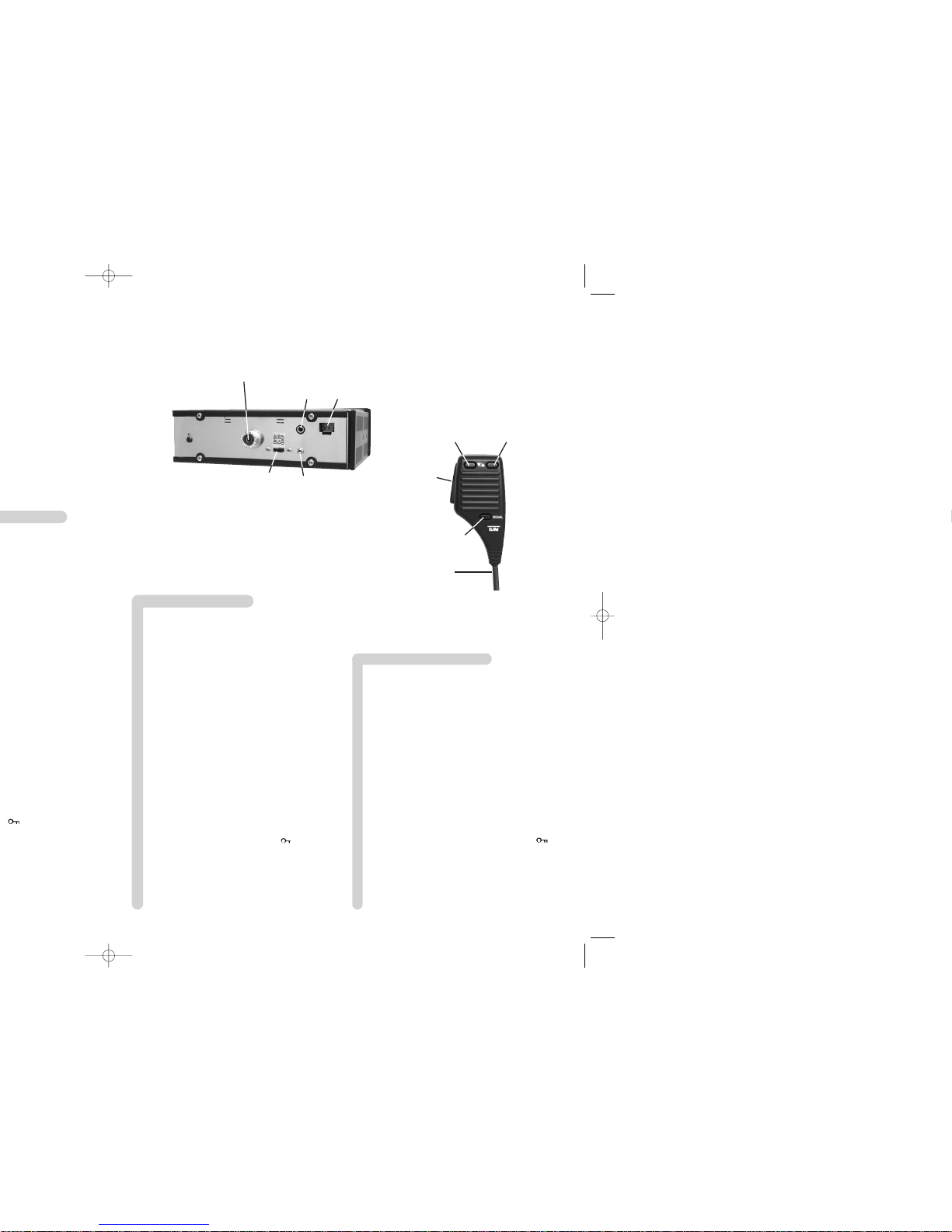
1 Microphone avec câble torsadé et fiche 6 broches
2 Touche de sélection de canaux vers le haut [ S ]
3 Touche de sélection de canaux vers le bas [ T ]
4 Touche d'émission [ PTT]
5 Touche de la tonalité [ SIGNAL]
6 Afficheur du type LCD
7 Réglage du volume et marche / arrêt [ Vol / Off ]
8 Réglage du squelch et marche / arrêt du squelch
automatique [ SQ / Asq ]
9 Sélecteur rotatif de canaux [ Channel ]
10 Prise du microphone 6 broches ( standard GDCH )
11 Touches de mémoire [ 1 - 4 ]
12 Touche de commutation du fonctionnement
AM/FM [ Mode ]
13 Commutateur marche / arrêt de la fonction VOX
14 Lampe témoin de la disponibilité de la fonction
VOX [ VOX ]
15 Touche de la recherche de canaux [ Scan]
16 Touche de sélection de l'éclairage de l'afficheur
LCD [ B ]
17 Touche de rappeler le canal dernier [ LCR]
18 Touche de commutation du ton de réception
[ Hi / Lo ]
19 Touche de contro de deux canaux et de la
verrouillage du clavier [ Dual Watch / ]
20 Touche canal 9 prioritaire [ CH9 ]
21 Connecteur d'antenne SO239
22 Prise d'alimentation
23 Prise jack ( 3,5 mm ) pour un haut-parleur externe
24 Prise jack ( 2.5 mm ) pour un S-mètre externe
25 Commutateur glissant de sélection des versions
[ 4040 / 8012 / 4000 ]
Français page 23- 35
Netherland pagina 45 - 53
1 Microfoon met spiraal kabel en 6 pin plug
2 Kanaal selectie omhoog [ S ]
3 Kanaal selectie omlaag [ T ]
4 Push to talk toets [ PTT ]
5 Oproeptoon toets [ SIGNAL ]
6 LC display
7 Volume bediening, Aan/Uit schakelaar [ Vol / Off ]
8 Squelch bediening + automatische squelch [ SQ/Asq ]
9 Draai schakelaar voor de kanalen [ Channel ]
10 Microfoon aansluiting 6 pin ( GDCH standaard )
11 Toetsen voor geheugens [ 1 - 4 ]
12 AM/FM schakelaar [ Mode ]
13 VOX functie aan/uit schakelaar
14 Standby LED van de VOX functie [ VOX ]
15 Toets voor scannen van de kanalen [ Scan ]
16 Keuze toets voor LCD achtergrond verlichting [ B ]
17 Last channel recall toets [ LCR ]
18 Toets voor de omschakeling van de toon [ Hi / Lo ]
19 Dual Watch of toetsen blokkering [ Dual Watch / ]
20 Kanaal 9 priority toets [ CH9 ]
21 Antenne aansluiting SO239
22 DC voeding connector
23 Jack aansluiting ( 3.5 mm ) voor externe luidspreker
24 Jack aansluiting ( 2.5 mm ) voor externe Signaal meter
25 Schakelaar voor de selectie van:
[ 4040 / 8012 / 4000 ]
1
5
4
2
3
21
22
23
24
25
32
Page 3

Setting up the TEAM RoadCOM
1) Installation of a CB antenna
The antenna is one of the most important parts of the equipment. The type of antenna and its
location has a great effect on the range of operation. Please consider the following criteria for
selecting the best location and installation of your antenna:
> Make sure that the antenna is designed for radio operation on 27 MHz.
> The location of the antenna should be as high as possible without any obstacles nearby.
> The aerial cable should not be damaged and the plugs should be properly connected.
> Make sure that the antenna cable is not bent too strong.
> The bigger the mechanical size of the antenna, the higher the range of operation.
When you install a mobile antenna please note the following advice:
> The antenna should be fixed in the centre of a bigger part of the coachwork.
> The mobile antenna coil should have the closest possible contact with a conducting metallic
surface of the bodywork of the car.
There are also some other possibilities to fix the antenna onto the car without the necessity
to drill a hole into the bodywork of your car, for example mounting the antenna onto the gutter, mounting the antenna onto a holder on the cover of the boot or using an antenna with a
magnetic foot or using a windscreen antenna.
For base-station operation we recommend a stationary antenna on the roof, for example the
TEAM ECO 050 or ECO 200.
> Please don't mount the CB antenna nearby a radio or TV antenna to prevent interference
of radio or TV reception.
> Keep an eye on power lines running along nearby when mounting the antenna on the roof.
" DANGER "
> The base-station antenna has to be connected via a lightning arrester.
> All connected cables including the antenna cable must not exceed a length of 3 m.
2) Aerial Connection
Before pressing the transmit key, a suitable aerial must be connected. The PL259 plug of the
aerial cable ( coax ) is connected to the SO239 socket ( 21 ) on the rear panel. Make sure,
that all plugs are firmly tightened and properly soldered. Unsatisfactory connections can damage the radio and will reduce the range of operation.
The antenna should be matched with the radio, otherwise a part of the transmit power will be
reflected at the antenna and will not be radiated. This causes also a drop in the range of operation. The matching can be carried out by a length adjustment of the antenna radial for a minimal SWR ratio which can be measured by a SWR meter ( e. g. TEAM SWR 1180P ). After
the measurement the SWR meter should be removed from the antenna line.
3) Installation in the car
When you want to fix the unit in your car, you can either fasten it with the help of the included mounting bracket below the dashboard, or insert it into a car radio slot by using the included inserting frame. Always mount the transceiver where the switches are easily accessible.
Other important points of view for the correct mounting position are:
Page 4

Operation of the TEAM RoadCOM
1) Switching on [ Vol / Off ]
Before switching the unit set the squelch control ( 8 ) [ SQ / Asq ] to the counterclockwise
stop but without activating the internal switch. The device is switched on by turning the volume control ( 7 ) [ Vol / Off ] clockwise to the centre position. The symbols are shown at the
LC display ( 6 ) and the LCD backlight is illuminated. When being switched on after a disruption of the supply source the unit works on channel number 9 in FM mode and the LCD backlight is illuminated in orange or blue. Adjust the receiver sound with the volume control to the
desired level.
All settings, which are made during operation of the transceiver, remain memorised after the
unit is switched off, as long as the power supply is not disrupted.
2) Squelch [ SQ / Asq ]
The strong background noise, which occurs always on free channels, can be suppressed by
the squelch function. By turning the squelch control ( 8 ) [ SQ / Asq ] slowly clockwise you
will find a point where the noise disappears. The squelch control should only be turned up far
enough to stop the background noise on an unused channel. Turning the control further clockwise will increasingly suppress stronger interfering signals as well as weak stations.
The automatic squelch [ Asq ] can be activated by turning the squelch control counterclockwise until the control clicks. In this position the normal squelch function is switched off and
the squelch threshold is set to default.
3) Confirmation tones
In reception mode all entries made by the keys, except the VOX function On/Off switch ( 13 ),
the PTT key ( 4 ) [ PTT ] and the call tone key ( 5 ) [ SIGNAL ] will be confirmed with a short
receipt tone. If you want to switch off the tones, press the channel scanning key ( 15 )
[ Scan ] for about 2 to 3 seconds, until a second, short receipt tone comes from the speaker.
Now, the unit will be silent, if any keys are pressed.
In the same way, the receipt tones can be reactivated.
4) Channel selection [ S ] [ T ]
All channels can be selected by pushing the channel selector keys ( 2 ) [ S ] and ( 3 ) [ T ]
at the microphone, or by turning the rotary channel selector ( 9 ) [ Channel ] on the front panel
to the desired channel. The channel will be displayed on the LCD ( 6 ) with big digits and the
frequency with small digits. No channel selection is possible while the radio is in TX mode.
The channels step in a ring like system. That means you go from the highest channel number to channel 1 and vice versa. For communication with a partner CB station, both transceivers must be adjusted to the same channel and the same modulation type.
5) Audio reproduction sound selection [ Hi / Lo ]
The RoadCOM is equipped with an audio reproduction sound toggle key ( 18 ) [ Hi / Lo ].
When being switched on after a disruption of the supply source the receiving sound is set to
mellow, which is indicated in the LCD by the symbol "LO". By pushing the audio reproduction
sound key ( 18 ) [ Hi / Lo ] the receiving tone is changing to a bright sound in the loudspeaker. This is indicated in the LCD window by the symbol "HI". By pushing the sound key again,
the receiving tone is changed back to mellow, indicated by the symbol "LO".
Page 5

ENGLISHENGLISH
9) Transmitting
To transmit depress and hold the key ( 4 ) [ PTT ] on the microphone ( 1 ). ). At the LCD the
symbol "TX" appears, and the bar meter at the bottom of the display shows the relative transmit signal strength. The sensitivity of the microphone ( 1 ) has been set to give good results
speaking normally at a distance of 2 - 4 inches. Speaking too loudly will cause distortions and
make the signal difficult to understand. While the set is in the transmit mode there is no key
entry possible and the receiver is muted. On completion of the transmission release the PTT
key ( 4 ) and the set will revert to receiving mode.
10) Call tone
If you press the transmit key ( 4 ) [ PTT ] and the call key ( 5 ) [ SIGNAL ] at the same time
on the microphone ( 1 ), a call tone will be transmitted and can be heard only by the partner
station, provided it is switched on the same channel and the same modulation type.
11) Channel memory keys [ 1 - 4 ]
The RoadCOM can store up to 4 frequently used channels and their modulations. The default
settings of the memories 1 - 4 are the channels 1, 9, 19 and 40 in FM mode. These memories can be overwritten with other channel numbers and modulation types. In case of data
loss the default settings will be stored in the memories again.
If you want to save a new channel you have to select it first with the channel selector switch
( 9 ) [ Channel ] or the channel selector keys ( 2 ) [ S ] and ( 3 ) [ T ]. Then adjust the desired modulation type. Then depress one of the memory keys ( 11 ) [ 1 - 4 ] for about 3 to 4
seconds until a second receipt tone and a short flashing of the channel number and the channel frequency indicate the overwriting of the new channel number and modulation type into
the corresponding memory.
If you want to recall a memorised channel and the corresponding modulation type you have
to depress briefly one of the memory keys ( 11 ) [ 1 - 4 ]. On the left side of the display the
actual memory number is displayed behind a "M" in case of data storage or recall. The memory number indication disappears by selecting a new channel.
12) Last channel recall [ LCR ]
By a brief depressing on the key ( 17 ) [ LCR ] the transceiver will return to that channel and
that modulation type, to which it was adjusted, when the PTT key was pressed the last time.
The actual channel and the actual modulation type will be stored temporarily in a register. If
you press on the key ( 17 ) [ LCR ] once again, the unit will skip back to the previously selected channel and modulation type stored in the register, provided, that you did not change the
channel and/or the modulation type in the meantime.
13) Priority Channel 9 / 19 [ CH9 ]
The version “8000uk” is equipped with the priority channels 9 and 19. Priority channel 9 is selected by pressing the key ( 20 ) [ CH9 ] once. To set priority channel 19, press the key ( 20 ) [ CH9 ]
twice. When a priority channel is set, the channel and the frequency will blink in the display and
all function keys including the rotary channel selector are disabled. Only transmission and activation of the VOX function are possible. To return to the previous channel, press the key
( 20 ) [ CH9 ] once, if priority channel 19 has been selected, or twice, if priority channel 19 has
been set. Once returned to regular mode, all functions will be enabled again.
All other versions are only equipped with the priority channel 9.
Page 6

( 3 ) and the rotary channel selector ( 9 ). Thus it is also impossible to stop most activated
functions. Only transmission is possible. The function remains even active if the unit is switched off in the meantime, provided that the supply voltage remains connected.
To deactivate the key lock function depress the key ( 19 ) [ Dual Watch / ] once again and
hold it for a short period, until you will hear 2 seconds later a second short receipt tone which
indicates that the key lock function is deactivated now. At the same time the key symbol " "
disappears from the display. Now the keys are released again.
17) VOX function
The VOX function is a voice activated control of the transmitter. That means talking into the
microphone will make the transceiver turn automatically to transmit mode. Thus keeping the
PTT key on the microphone depressed during sending out a message becomes unnecessary. To prevent an unwanted transmission the VOX circuit in the RoadCOM is coupled with the
squelch circuit of the receiver. This has the effect, that the voice activated switching on of the
transmitter by sound signals from the microphone can only take place, when the squelch is
closed at the same time. Therefore make sure that the squelch is closed on free channels
before you activate the VOX function. this function.
To activate the VOX function depress the button of the VOX function On/Off switch ( 13 ) on
the left side of the front panel until it latches. If now the actual channel is free and the squelch
is closed, the red standby LED of the VOX function ( 14 ) [ VOX ] lights up. This indicates that
the unit is ready for radio operation with the VOX function now.
If you speak loud enough into the microphone, the unit will switch itself automatically to transmit
mode, which will be indicated by the symbol "TX" on the LCD. The LED ( 14 ) [ VOX ] remains
alight also in transmit mode. During your message it may occur, that the actual loudness of your
voice falls below the volume level, which is necessary for the VOX function to make the unit
switch to transmit mode. If the duration of those periods of low speech level remains below a certain time, which is called the VOX delay time, the unit will stay in transmit mode. If the duration
of those periods exceeds the VOX delay time, the unit returns to the receive mode. In this
moment the LED ( 14 ) [ VOX ] switches itself briefly off and on again.
If the squelch is open for some reasons, the LED ( 14 ) [ VOX ] will be dark, even with activated
VOX function. One reason for an open squelch could be that there is a station on the channel,
for example the partner station. Another reason could be that the noise level has increased so
that the squelch remains open also on a free channel. In this case the unit will
not switch itself to transmit mode by talking into the microphone, no matter how loud you speak.
The unit can be switched to transmit mode by the help of the transmit key on the microphone at every time, also with active VOX function.
To deactivate the VOX function depress the button of the VOX function On/Off switch ( 13 )
until it is released.
18) External speaker jack
The RoadCOM is equipped with a 3.5 mm jack socket ( 23 ) at the rear panel to connect an external speaker of 4 - 8 ohm impedance. At 4 ohms the speaker load can be 4 watts ( e.g. TEAM
TS-500 ). When the external speaker is connected, the internal speaker will be switched off.
19) Signal meter internal/external
The bar meter in the LCD window shows in reception mode the signal strength of a received signal ( S value ), and in transmit mode the signal strength of the transmit signal. There is also a 2.5
mm jack socket ( 24 ) at the rear panel of the RoadCOM to connect an external S-meter with a
2.5 mm plug ( e. g. TEAM SM 930 ). It can show the S values more exactly. Please note that the
external S-meter shows only the relative field strength of the incoming signal.
Page 7

Page 8

Page 9

TEAM RoadCOM
Kanal- & Frequenztabelle / Channel- & Frequency Table / Tableau Canaux & Fréquence /
Tabla de canales y frecuencias / Kanalen en frequentietabellen
01 - 26.965
02 - 26.975
03 - 26.985
04 - 27.005
05 - 27.015
06 - 27.025
07 - 27.035
08 - 27.055
09 - 27.065
10 - 27.075
11 - 27.085
12 - 27.105
13 - 27.115
14 - 27.125
15 - 27.135
16 - 27.155
17 - 27.165
18 - 27.175
19 - 27.185
20 - 27.205
21 - 27.215
22 - 27.225
23 - 26.255
24 - 27.235
25 - 27.245
26 - 27.265
27 - 27.275
28 - 27.285
29 - 27.295
30 - 27.305
31 - 27.315
32 - 27.325
33 - 27.335
34 - 27.345
35 - 27.355
36 - 27.365
37 - 27.375
38 - 27.385
39 - 27.395
40 - 27.405
41 - 26.565
42 - 26.575
43 - 26.585
44 - 26.595
45 - 26.605
46 - 26.615
47 - 26.625
48 - 26.635
49 - 26.645
50 - 26.655
51 - 26.665
52 - 26.675
53 - 26.685
54 - 26.695
55 - 26.705
56 - 26.715
57 - 26.725
58 - 26.735
59 - 26.745
60 - 26.755
61 - 26.765
62 - 26.775
63 - 26.785
64 - 26.795
65 - 26.805
66 - 26.815
67 - 26.825
68 - 26.835
69 - 26.845
70 - 26.855
71 - 26.865
72 - 26.875
73 - 26.885
74 - 26.895
75 - 26.905
76 - 26.915
77 - 26.925
78 - 26.935
79 - 26.945
80 - 26.955
1A - 26.83
2A - 26.87
3A - 26.93
Kanal - Frequenz ( MHz ) /
Channel - Frequency ( MHz ) /
Canaux - Fréquence ( MHz ) /
Canal - Frecuencia ( MHz ) /
Kanaal - Frequentie ( MHz )
Page 10

Page 11

 Loading...