

Page 1

PT617A ( VHF )
PT618A ( UHF )
Mobilfunkgerät
Mobile Transceiver
Bedienungsanleitung
Manual
Page 2

20 21
Dear customer,
The following instructions will help to prolonge your radios life.
Do not expose the transceiver for a long period to direct sunlight, nor
place the transceiver close to heating appliances.
Do not place the transceiver in excessively dusty areas, humid areas,
or on unstable surface.
If an abnormal odor or smoke is detected, immediately turn the power
off.
Do not touch the power plug with wet hands.
Do not modify this transceiver for any reason.
Refer service to qualified technician only.
CONTENTS
page
1. Unpacking and Checking Accessories 22
2. Preparation
2.1 Power Cable Connection 22
2.2 Radio Installation 22 - 23
2.3 Installation of a CB antenna 23
2.4 Aerial Connection 24
3. Getting Acquainted
3.1 Front Panel and Microphone 24
3.2 Display 25
3.3 Rear Panel 25
4. The Secondary Functions
4.1Transmission Power Selection 25
4.2 Setting Squelch Level 26
4.3 Setting Time-out-timer 26
5. Basic Operations
5.1 Turn the Power Switch ON or OFF 26
5.2 Adjusting the Volume 26
5.3 Transmitting Operation 27
5.4 Receiving Operation 27
5.5 Change Channel 27
6. Scan Options
6.1 Start Scanning 27
6.2 Priority Channel 27
6.3 End Scanning 27
6.4 Time-control 28
6.5 Carrier Wave Control 28
6.6 Calling Back 28
7. Other Operations
7.1 Time-Out-Timer(TOT) 28 - 29
7.2 Busy Channel Lockout(BCL) 29
7.3 Monitor 29
7.4 Clear Tail Tone 29
7.5 CTCSS/DCS 29
7.6 DTMF 29 - 30
7.7 2-Tone Signaling 30
7.8 5-Tone Signaling 30 - 31
7.9 Talk Around 31
7.10 Reverse Frequency 31
7.11 Auto Channel Selection (ACS) 31
7.12 Repeater Signals 32
8. Self-programming Mode 32
8.1 Select Channel 32 - 33
8.2 Set Operating Frequency 33
8.3 Set CTCSS/DCS Encode and Decode 33
8.4 Set the Channel Spacing 33 -
8.5 Transmission Prohibited on Busy Channel
8.6 Add or Delete Channel in the Scan List
8.7 Add or Delete Compander
8.8 Set Priority Channel
9. Trouble Shooting
10. Specification
11. Frequency Table
GB
GB
The use of commercial frequencies requires a licence and
charges apply.
We recommend you to get your radio programmed by an authorized TEAM dealer only. The programming has to follow the
regulations and rules in general and the restrictions of the
licence.
manual.qxp 14.07.2006 16:08 Seite 21
Page 3
22 23
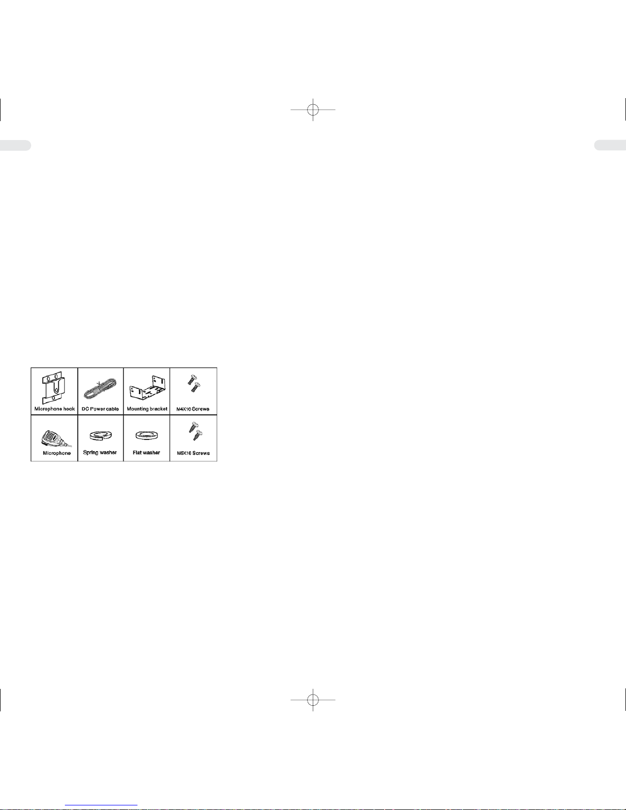
1. Unpacking and Checking Accessories
Please take out the transceiver from the packing box carefully. You are
advised to check the supplied accessories according to the following list,
before you throw away the packing case. If you find something is lost or
damaged in transportation, please contact the dealer immediately.
SUPPLIED ACCESSORIES
ACCESSORIES QUANTITY
Mounting bracket 1
DC Power cable 1
Microphone 1
M5X16 Self-taping screw 4
M4X16 Self-taping screw 3
Spring washer 4
Flat washer 4
Microphone hook 1
Instruction Manual 1
Guarantee card 1
2 Preparation
2.1 POWER CABLE CONNECTION
Check if there is a hole for power cable in the adiabatic panel. If there
is no hole, drill one in it and fix a rubber hole ring in the hole.
Thread the two power cables through the hole of the adiabatic panel
from the cabinet into the engine chamber. Connect the red wire with
the battery positive terminal + , and the black wire with the negative -.
Roll up the surplus wire and stick it at a place. Notice: Make sure the
wires are loose enough for the convenience of repairing the radio in
the connection state.
2.2 Radio Installation
Warning:
To ensure the passengers' safety during driving and avoid radio's
looseness and fall-off when bumping, please fix the radio with the
mounting bracket.
Mark the position of the mounting bracket and drill holes on the instrument panel. And then fix the mounting bracket, the flat washer and the
spring washer with 4 M5 16 tapping screws. The radio should be fixed
at a place convenient for operation, and sufficient space should be
reserved for wire connection.
Screw out the 4 M4 16 screws, flat washer and spring washer from the
two sides of the radio. Slide the radio into the mounting bracket and
fixed it with the 4 M4 16 screws screwed out just now.
Connect the antenna and power cable with the radio.
Fix the microphone hook at a convenient place with 3 M4 16 screws.
The microphone and its wire should be fixed at a place not affecting
safe driving.
Plug the microphone connector into the jack in the radio's front panel
and hang the microphone on the microphone hook.
Notice:
When change the fuse of the DC power cable, make sure to use a fuse
of the same spec. Afuse of higher capacity is prohibited.
2.3 Installation of an antenna
The antenna is one of the most important parts of the equipment. The
type of antenna and its location has a great effect on the range of operation. Please consider the following criteria for selecting the best location and installation of your antenna:
> Make sure that the antenna is designed for radio operation on the
designated frequency range.
> The location of the antenna should be as high as possible without
any obstacles nearby.
> The aerial cable should not be damaged and the plugs should be
properly connected.
> Make sure that the antenna cable is not bent too strong.
> The bigger the mechanical size of the antenna, the higher the range
of operation.
When you install a mobile antenna please note the following advice:
> The antenna should be fixed in the centre of a bigger part of the
coachwork.
> The mobile antenna coil should have the closest possible contact
with a conducting metallic surface of the bodywork of the car.
There are also some other possibilities to fix the antenna onto the car
without the necessity to drill a hole into the bodywork of your car, for
example mounting the antenna onto the trunkor using an antenna with
a magnetic mount or a windscreen antenna.
> Please do not mount the antenna nearby a radio or TV antenna
to prevent interference of radio or TV reception.
> All connected cables including the antenna cable must not exceed
a length of 3 m.
GB
GB
manual.qxp 14.07.2006 16:08 Seite 23
Page 4

24 25
3.2 Display
( 888.88.8 ) Indicate the current channel frequency or channel No.
( A) Displays that current channel has been added to
the scanning list.
( P ) Displays Priority channel.
( DQT ) Active CTCSS Code
( QT Acitve DQT Code
( SCAN ) Acitive Scan Function
( >>>>>>> ) RSSI ( Receive-Signal-Strength-Indicator )
( H M L ) Indicates power level ( high, medium or low )
( F ) Indicates secondary function mode.
( lock ) Indicates key lock.
( PC ) Indicates data transmission
( 25 / 50 / 75 ) Frequencies with 5 digits, will specifiy their last two
digits with one of the numbers.
Notice:
Any key action will light the LCD for about 10 seconds. If the keys have
no action in 10 seconds, the background light of LCD will
be turned off automatically.
3.3 Rear Panel
1 - Jack for power cable plug 1
2 - Jack for external speaker
3 - Jack for antenna
4 The Secondary Functions
Note: the secondary function can be prohibited by dealer.
4.1 Transmission Power Selection
You may select high RF power, medium RF power or low RF power
conveniently. Press FUN key, the F indicator will light ,then press the
key to select transmission power,e.g. L
Press the / keys to select RF power you want. After the transmission power have been selected, H, M or L indicator will light on LCD. It
means that current transmission power is high, medium or low respectively. Press FUN key to confirm it. If you do not want to change the
transmission power, press the B key to cancel the current setting.
GB
GB
2.4 Aerial Connection
Before pressing the transmit key, a suitable aerial must be connected.
The BNC-plug of the aerial cable has to be connected to the socket
on the rear panel. Make sure, that all plugs are firmly tightened and
properly soldered. Unsatisfactory connections can damage the radio
and will reduce the range of operation.
The antenna should be matched with the radio, otherwise a part of the
transmit power will be reflected at the antenna and will not be radiated. This causes also a drop in the range of operation.
3. Getting Acquainted
3.1 Front Panel and Microphone
1. PWR-Power switch
Press and hold this switch about 2 seconds, then power turn on/off.
2. LED indicator
Be red while transmitting and green while receiving a signal.
3. / keys
Press these keys to select the operation channel, with FUN key to
set the other functions. (See page 8 for additional information on
this function.)
4. Channel A/ B
If have been set up channel Aor B, press one of the key to choose
channel Aor B, with FUN key to set the other functions. (See page
8 for additional information on this function.)
5. Volume control
Use this control to adjust the volume from the speaker. Clockwise
rotation increases the volume; counterclockwise rotation decrease
the volume.
6. SCAN, FUN and MON Keys
SCAN key, when more than two channels are added to the scan
list, use this key to start up scan function. (Reference to channel
scan), with FUN key to set the other functions. (See page 8 for additional information on this function.)
7. Jack for microphone or programming cable connector
This jack is used for handset microphone, and it is used for programming cable connector too.
8. PTT key (on microphone)
Press PTT key, then enter transmission state release this key, then
return to standby mode.
manual.qxp 14.07.2006 16:08 Seite 25
Page 5

26 27
4.2 Setting the Squelch Level
Y ou may select the proper squelch level , and there are 10 levels (0~9)
selectable in all. If level 0 is set, the squelch will be turn off completely. Press FUN key, the F indicator will light, then press the MON key to
set squelch level. The current squelch level will be displayed on LCD,
e.g. Sql 0.
Press / keys to select the proper squelch level. The current
squelch level will be displayed on LCD, e.g. Slq 9.
After you have selected the proper squelch level, press FUN key to
confirm. But if you want to cancel the current setting, please press B
key to exit.
4.3 Setting Time-Out-Timer (TOT)
The transceiver has a time-out-timer function to prevent possible problem caused by continuous transmission. You may set the proper timeout interval for transmitting.
The time-out interval is 30s, 60s, 90s, 180s, 900s or OFF (no limit).
Press FUN key, indicator will light, then press SCN key to set time-outtimer. The current time-out interval will be displayed on LCD, e.g.
to 90.
Press / keys to select your desired time-out interval. LCD displays the selectable time-out interval, e.g. tot of.
Then press FUN key to confirm. But if you want to cancel the current
setting, please press B key to exit.
5. BASIC OPERATIONS
5.1 Turn the Power Switch On Or Off
Press and hold the PWR key about 2 seconds to turn the power on or
off. When turn the power on, all indicators will be displayed on LCD for
1 second.
After a long beep tone , it goes in working mode. If there is no channel was stored, it displays as no chn. and LED lights red.
5.2 Adjusting the Volume
Use this control to adjust the volume from the speaker. Clockwise rotation increases the volume; counter-clockwise rotation reduces the volume.
When adjusting the volume, you may press MON key to monitor the
background noise.
5.3 Transmitting Operation
Make sure the selected channel is free before transmitting. You may
press the PTT key and speak to the microphone after the LED lights
red, release the PTT key to receive.
5.4 Receiving Operation
The dealer may have set CTCSS/DCS for the transceiver.
If you are using the channel with CTCSS/DCS, you will not receive
(decode, or open squelch) unless the selected encode tone is received.
If you are using the channel without CTCSS/DCS, you can receive the
signals from any transceiver.
5.5 Change Channel
Press the / key to increase or decrease the channel number consequently. The channel number will be displayed on the LCD.
If you press and hold the / key over 1 second, the channel number will increase or decrease continuously, and be displayed on LCD.
Press any key to stop.
If the selected channel has been set as priority channel, the P indicator will light on LCD. If the selected channel has been added in the scan
list, the A indicator will light on LCD. If the selected channel has been
set CTCSS/DCS, the QT or DQT indicator will light on the LCD.
6. Scan Options
Scan function is very effective in monitoring signal on the programmable channel. The transceiver will scan all channels while scanning,
which have been added in the scan list. This function may be prohibited by local dealer.
Notice:
Scan function is deactivated until more than two channels have been
added in the scan list.
6.1 Start Scanning
Press the SCN key to enter the scan state. Start scanning from the current channel, increase by the channel number. The SCN indicator and
icon will light on the LCD.
6.2 Priority Channel
If the transceiver has been set priority channel by dealer, it will be monitoring the priority channel while receiving other channel signals. When
having received the priority channel signals, the P will be displayed on
the LCD.
6.3 End Scanning
Press the SCAN key to end scanning during the scan. It will stop on the
channel that receives a signal, or the channel before scanning.
GB
GB
manual.qxp 14.07.2006 16:08 Seite 27
Page 6

28 29
6.4 Time-Control
The radio will restart the scan after pausing for some time while receiving signal .The pausing time can be preset from 0.5 to 5 seconds.
6.5 Carrier Wave Control
The radio will pause the scan after receiving signals and will restart
scan after the signal disappears.
6.6 Calling Back
The working channel of the radio will return to the following channels
automatically by pressing PTT during the scan. The dealer can select
one among the following four ways.
1) Selected channel:
When pressing PTT during the scan, the radio will always transmit
from the first channel of the scanning list.
2) Selected channel or currently working channel:
If pressing PTT during scanning, the radio will transmit from the first
channel in the scanning list. If pressing PTT during the scan pausing, the radio will transmit from current channel.
3) Prior channel:
The radio will always send signals from the prior channel in the scan
list when pressing PTT.
4) Prior channel or currently working channel:
When the radio is scanning, it will send signals from the prior channel in the scanning list by pressing PTT. During the pause of scan,
the radio will transmit from current channel by pressing PTT.
7 OTHER OPERATIONS
7.1 Time-Out -Timer (TOT)
Caused by continuous transmission. If you transmit con-tinuously over
the preset time, the unit will stop the transmitting and return to standby
mode.
Time Out Timer
The purpose of the Time -out- timer is to prevent any single person
from using a channel to transmit for an extended period of the time. If
you continuously transmit longer than the time limit preset by the distributor, the radio will stop transmitting and a tone will be heard. To stop
the tone, release the PTT button. You can press the PTT again to
resume transmitting.
TOT Pre-Alert
The TOT Pre-Alert function notifies that the programmed time is
expired. This should be set less than TOT value. Rang: Off /1 to 10s
(1s steps) Default: Off
TOT Rekey Time
TOT Rekey-Time sets the penalty time in which the radio can not
be rekeyed for transmitting after the Time-Out-Timer setting is
exceeded.
Range: Off /1 to 60s (1s steps)Default: Off
TOT Reset Time
TOT Reset Time sets the minimum wait time allowed between transmissions that will reset the Time-Out -Timer. When TOT Reset Time is
set , it causes the TOT continue even after PTT is released unless the
TOT Reset Timer has expired.
Range: Off /1 to 15s (1s steps)Default: Off
7.2 Busy Channel Lockout (BCL)
The function of busy channel lockout (BLC) is turned ON or OFF by the
local dealer, also can be set by user in self-programming mode.
When the BLC function is on, it can prevent other transceivers from
interfering with your transceiver by using the same frequency. When
press the PTT key, a beep alarm will ring until the PTTkey is released
and it will go back to stand-by mode, if the channel is busy.
7.3 Monitor
When there is no signal, the squelch circuit will mute the speaker automatically and you will not hear the background noise. To inactivate the
squelch circuit, press the MON key, which is very useful when you
adjust volume or want to receive weak signals. When pressing the
MON key, the status indicator lights green and the radio is in the state
of monitoring.
7.4 Clear Tail Tone
When using the channel set with CTCSS/DCS, the after sound in talking ending can be eliminated.
7.5 CTCSS/DCS
Y our dealer can program CTCSS/DCS signaling on the radio channels.
CTCSS/DCS allows you to ignore (not hear) calls from other parties
who are using the same channel.
The channel preset with CTCSS/DCS signaling can activate the
squelch only when it receives the correct CTCSS/DCS signaling. Likewise, only the radios whose CTCSS/DCS is the same as yours can
hear the signals you transmit.
Using a CTCSS/DCS channel does not mean your calls are private. If
other parties' CTCSS/DCS is identical with yours, they can hear your
calls.
7.6 DTMF
The dealer can activate or inactivate this function by programming.
1) Receiving Signals
Only when the radio receives the programmed DTMF code (3~10
digits), the squelch will be activated. Usually every channel has unique code. Calls from the radios that are not programmed with matching codes will not be heard.
The dealer can also program group codes on the radio.
GB
GB
manual.qxp 14.07.2006 16:08 Seite 29
Page 7

30 31
When receiving the signals with proper DTMF code, the squelch will
be activated, and you can receive the call.
The LED flashes orange.
The dealer can program that squelch turns off after a certain time
and LED turns dim.
If DTMF auto reply has been programmed, the calling radio will
receive confirming signals.
If DTMF signal reminder has been programmed, it rings when
receiving the proper code.
2) Transmitting Signals
Y ou can transmit the preset DTMF PTTID code by pressing the PTT
button. Or you can also transmit the DTMF code by pressing the
function button CALLA or CALLB if the DTMF signaling has been
programmed on the channel.
7.7 2-Tone Signaling
The dealer can activate or inactivate this function by programming.
1) Receiving Signals:
When receiving the proper 2-Tone signaling, the squelch will be activated, and you can receive the call. The LED flashes orange.
T o manually mute the speaker, press the monitor key or the side button set as instantaneous monitor.
The dealer can program that the squelch turns half active certain
time after the signal disappears.
If auto reply has been set, the calling radio will receive confirming
signals.
If signal reminder has been set, the warning tone sounds when the
radio receives the proper 2-Tone code.
2) Transmitting Signals:
If the 2-Tone signaling has been set on the channel, you can transmit the 2-Tone signals by pressing the side button CALLAor CALLB,
which can be set by the dealer.
After transmitting the signal, indicator flashes orange and you can
talk to other radios until the effective time expires and the indicator
turns dim.
7.8 5-Tone Signaling
The dealer can activate or inactivate this function by programming.
5-Tone Signaling has 7 coding formats: CCIR, ZVEI1, ZVEI2, DZVEI,
EEA, PZVEI, and EIA.
1) Receiving Signals:
When receiving the proper 5-tone signal, the squelch will be activated,
and you can receive the call. The LED lights orange.
The dealer can program that the squelch turns half active certain
time after the signal disappears.
If auto reply has been set, the calling radio will receive confirming
signals.
If signal reminder has been set, the warning tone sounds when the
radio receives the proper 5-Tone signals.
2) Transmitting Signals:
If the PTT ID on the channel you select has been set with 5-Tone,
the 5-Tone signal will be transmitted when making a call.
Or transmit the 5-Tone signal by pressing the PTT button and
CALL1 or CALL2 button, which can be set by the dealer.
7.9 Talk Around
When the radio is out of the repeater service range, or the repeater is
cut off due to power failure or any other reasons, you can communicate
with other radios by the Talk Around function. However, it might be
unable to communicate with others if it is too far away or it is hindered
by geographical obstruction.
You can set the Aor B keys to start or end the Talk Around.
When in the Talk Around communication, the radio receiving and transmitting frequencies are the receiving frequencies set in the original programming (communication in the same frequency). The CTCSS/DCS
encoding and decoding will be resumed to the original decoding audio
if they have been set differently.
7.10 Reverse Frequency
The dealer can set the reverse frequency function instead of the Talk
Around on your radio.
When the reverse frequency is active, the transmitting and receiving
frequencies are exchanged with each other. CTCSS/DCS encoding
and decoding are also exchanged.
Y ou can set the Aand B keys to start or end the reverse frequency communication.
7.11 Auto Channel Selection (ACS)
If there is more than one local repeater, the user can activate the ACS
function to scan these repeaters separately to find the desired repeater.
The user can select the ACS function by setting the A and B keys.
When the radio is in the ACS receiving state, press the PTT button to
reply on the channel that receives the strongest signals. You cannot
reply if it is in transmitting state.
When the user exits the ACS state, the radio will stay on the channel
that receives the strongest signals.
GB
GB
manual.qxp 14.07.2006 16:08 Seite 31
Page 8

32 33
7.12 Repeater Signals
1) Transmitting Beginning/Ending signals are used to join in or disconnect from some repeaters and calling systems.
2) The transmitting beginning signaling is used to join in the conventional repeater and its relevant auxiliary equipments. If the ID being
transmitted matches with the repeater's ID, it can use the repeater and
its auxiliary equipments.
3) The transmitting ending signaling is used to disconnect with the conventional repeater and its relevant auxiliary equipments. If the ID being
transmitted matches with the repeater's ID, it can disconnect from the
repeater and its auxiliary equipments.
8. Self Programming Mode
Notice: The channel can be set by the local dealer. You can also set
them by yourself freely. Self-programming mode can be prohibited by
dealer.
When the power is off, press the PWR key and key at the same time
to turn power on and enter self-programming mode. LCD displays:
SELF.
In self-programming mode, you can set the following items in turn by
pressing FUN key.
01: Select a channel
02: RX frequency
03: CTCSS/DCS decode
04: TX frequency
05: CTCSS/DCS encode
06: W/N channel spacing
07: Busy channel lockout
08: Add or delete channels in the scan list
09: Compander - On / Off
10: Priority - On / Off
You can also exit self-programming mode by pressing B key when
SELF displayed on LCD.
8.1 Select Channel
A. Press / key to select channel you need.(Press and hold key for
about over 1 second, you can select the channel consequently,
press any key to stop.)
Press FUN key and then the selected channel number will be displayed on LCD: CH 01.
B. After the channel is selected, you can delete the selected channel
by holding the SCN key for about 1 second. The DEL indicator will
be displayed on LCD, then press FUN key to delete the selected
channel data and return to next channel or press B key to cancel the
deleting of this channel - dEL.
C. Hold the Akey for about 1 second to light dELA on LCD and delete
all channels data. Then press A key to delete the selected channel
data and return to CH 01.Or press B key to cancel the deleting of
this channel.
Notice: When the DEL indicator or DELA indicator is light on LCD, it is
invalid to press FUN key, key and key.
8.2 Set Operating Frequency
If frequency has been saved in the channel, this frequency displays on
the LCD, e.g. 456.789. Otherwise displays as : ------------.
A. Press MON key to delete or set the frequency.
B. When the frequency is displayed, press the key or key to set
the frequency by step size to change the frequency. Press and hold
the key or key over 1 second to change the frequency consequently. The selected frequency will be displayed on the LCD.
C. Press B key to exit setting and return to CH 01.
D. Press A key to display the frequency step size on the LCD. Press
FUN key to confirm the selected step size.
E. Press FUN key to confirm and go to the next setting.
8.3 Set CTCSS/DCS Encode and Decode
In setting CTCSS/DCS encode and decode, press the MON key to
switch among OFF/ CTCSS/ POSITIVE DCS/ NEGATIVE DCS, the
default value is OFF.
When the CTCSS/DCS is selected, press the key or the key to
select the CTCSS frequency or DCS code. LCD displays the corresponding setting value. Press the FUN key to confirm the setting, and
enter the next item.
When the CTCSS/DCS is not selected, the LCD displays: oFF.
For the CTCSS (e.g. CTCSS 67Hz) the LCD displays: q 67.0.
For the positive DCS (e.g. DCS 023N), the LCD displays: d 023.
For the negative DCS (e.g. DCS 023 I), the LCD displays: d- 023
8.4 Set the Channel S
pacing
In this setting, press MON key to switch between 12.5kHz and 25kHz.
The default value is 25kHz. When the channel spacing is 25kHz, the
LCD displays: bAnd 1.
When the channel spacing is 12.5kHz, the LCD displays: bAnd 0.
Press the FUN key to confirm the setting, and enter the next item.
Press B key to exit.
GB
GB
manual.qxp 14.07.2006 16:08 Seite 33
Page 9

34 35
GB
GB
General
Frequency Range PT617A: 136 - 174 MHz, PT618A: 440 - 480 MHz
Channels 99
Channel space 25 kHz / 12.5 kHz
PLL steps 5 / 6.25 / 12.5 / 25 / 1000 KHz
Operating Temperature -30°C +60°C
Microphone impedance 2 kΩ
Antenna impendance 50 Ω
Modulation type PT617A: 16KF3E (W); PT618A: 8KF3E (N)
Frequency stability 2.5 x 10
Power supply DC 12,5 V
Operating Current 8A
Dimension(WHD) 140 mm x 40 mm x 145 mm
Weight 1000 g.
-6
∼
≥
Receiver
Sensitivity (12dB SINAD) PT617A: 0.25μV(W); PT618A: 0.28V(N)
Operating band width PT617A: 7KHz(W); PT618A: 3.5KHz(N)
Adjacent channel selectivity PT617A: 75dB(W); PT618A: 65dB(N)
Intermodulation reject ratio PT617A: 70dB(W); PT618A: 65dB(N)
Spurious response reject ratio 75dB
AF output power 2W (8Ω, distortion less than 5%)
Transmitter
RF power 1 - 25 W
Spurious and harmonics -70dB
FM noise (300~3000Hz) PT-617A: -45dB(W); PT618A: -40dB(N)
Audio distortion (3~30 kHz) 5%
Maximum frequency deviationPT-617A: 5kHz(W); PT618A: 2.5kHz(N)
+
-
+
-
≥
≥
≥≥
≥
≥
≥≥
≥
+
-
+
-
11 Specification10 Trouble Shooting
Cannot turn on or display is dim.
Power cable connection is not correct. Please connect the power
cable over again.
Cannot transmit.
Make sure that the PTT switch is pressed properly.
Noise is loud.
Out of the range of communication.
Cannot talk to or 4 hear each other in your group.
> Confirm the operating frequency is the same as the channel
frequency or not.
> Check CTCSS/DCS are the same or not.
> Out of the range of communication.
manual.qxp 14.07.2006 16:08 Seite 35
Page 10

For sale and use in :
A, B, CZ, D, DK, E, F,
FIN, GB, HR, I, L, N, NL, S
Mobile Transceiver
Bedienungsanleitung
TEAM Electronic GmbH
Bolongarostrasse 88; D-65929 Frankfurt am Main, Germany
phone ++49 / 69 / 300 950 0 - fax ++49 / 69 / 31 43 82
www.team-electronic.de - team-electronic@t-online.de
WEEE - Reg. Nr. DE 91930360 8 ( EAR ), 50635 ( ERA)
DSD 2617305, ARA2284
PT617A ( VHF )
PT618A ( UHF )
 Loading...