

Page 1
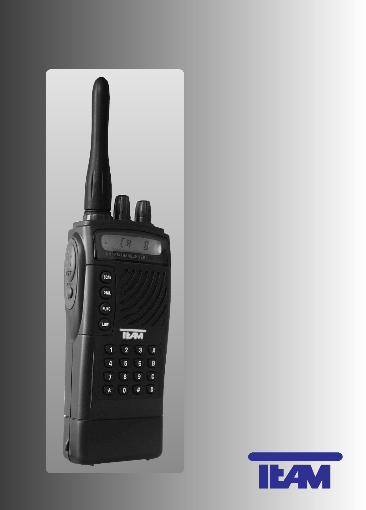
TEAM PT-3508 (3)
electronic
Bedienungsanleitung
Manual
PMR-446
&
optional
programmierbares
Amateurfunkgerät
430 - 440 MHz
PMR-446
&
optional
programmable
HAM-Radio
430 - 440 MHz
Page 2

TEAM PT-3508 (3)
manual
table of contents
page
Displays and Controls 2
Set-Up of the TEAM PT-3508 (3) 21
Installing and Removing the Rechargable Battery Pack 21
Installing and Removing the Belt Clip 21
Installing and Removing the Wrist Loop 21
Operation of the TEAM PT-3508 (3) with the Basic Functions 22
1) Turning ON/OFF Your Radio 22
2) Set Up the Volume 22
3) Channel Selection 22
4) Transmission 22
5) Reception 22 - 23
6) Jacks for External Ear- / Microphone 23
7) Charging the Rechargeable Battery Pack 23
8) Low Power Alert Function 23
9) Energy Saving Function 24
10) Scan Function 24
Muting Functions of the TEAM PT-3508 (3) 25
1) General 25
2) Description of the Procedures 25 - 26
3) Remarks about the Mute Functions 26
4) Programming the Different Mute Control Functions 26
5) Monitor Key Functions 26
6) Transmitting with the Different Mute Control Functions 27
7) Direct Transmission of DTMF Tones 27
8) Storage of DTMF Strings of Characters 27
9) Replay a Stored DTMF String Without Transmitting It 27
10) Transmission of a Stored DTMF String 28
11) Deletion of a Stored DTMF String of Characters 28
Additional Functions and Settings of the TEAM PT-3508 (3) 28
1) Setup of the Squelch Threshold 28
2) Temporary Change of the CTCSS Setting 28
3) Switch of a Channel`s Transmission and Reception Settings 29
4) Key Lock Function 29
5) Display Background Light Setting 29
6) Time-Out Timer ( TOT) 30
7) Transmission Lock on Busy Channels 30
8) Transmit Power Switch 30
9) VOX-Function 31
General 31
1) Security 31
2) Service 31
3) Declaration of Conformity 31
4) Programmed Channels 32
5) Programmed Functions 33
6) Specifications 33
7) CTCSS-Tones and DQT-Codes 34
Set-Up of the TEAM PT-3508 (3)
Unpack the PT-3508 (3) carefully. Make sure that none of the following items is missing. Should
any item be defective or missing, please contact your dealer immediately.
PT3508 (3) is a PMR handheld transceiver that can be programmed via the optional software
T-UP2 into a combined PMR-/ HAM-Radio. By default, PT3208 (3) contains only 8 PMR channels. The indicated channel numbers in the display refer to the according PMR channels that are
listed in the chapter General, paragraph 7) Specifications in the PMR Channel Table.
The transmitting power is set to 500 mW according to the European rules and regulations for
PMR handheld transceivers.
If you want to use the 70 cm frequency band radio channels, a HAM license is required. For
further details about this license and its requirements, contact the government agency for communication in your country that regulates these issues.
If you only use the default PMR channels, no license is required in most of the european countries.
Installing and Removing the Rechargeable Battery Pack
Installing
Carefully insert the rechargeable battery pack into the opening at the base of the
PT-3508 (3). Turn the rechargeable battery pack in such a way that the "Caution" label on the rechargeable battery pack will be at the front and the charging
contacts at the rear of the PT-3508 (3). Snap the rechargeable battery pack ( 15 )
into place by pushing until you hear a click. The unit is now ready for use.
Removing
To remove the rechargeable battery pack, turn the rear of the unit toward you.
Push the ribbed latch and, at the same time, pull the rechargeable battery pack
out of the PT-3508 (3).
Installing and Removing the Belt Clip
Attaching
The belt clip is to be attached at the rear of the PT-3508 (3). Remove the two screws
that are located above the label. Position the belt clip with the base pointing to the
bottom of the handheld transceiver and the upper part with the two holes touching
the unit's back part where the screws will be positioned and fasten the belt clip with
the two screws.
Detaching
Loosen the screws, remove the belt clip and put the screws back in position.
Installing and Removing the Wrist Loop
The metal ring for the wrist loop is located above the microphone / speaker jacks
[SP]/[MIC] ( 13 ) on the right side of the PT-3508 (3).
Attaching
Put the thin part of the wrist loop through the metal ring. Through the loop of the
thin part, pull the wide part of the wrist loop and pull until the knot is tight. Refer to
the image.
Detaching
Loosen the knot of the wrist loop at the metal ring and pull the wide part of the wrist
loop out of the loop. Finally, remove the wrist band from the metal ring.
21
ENGLISH
Battery Pack
Belt Clip Charger
Wrist Loop
Adapter
Manual
Declaration of Conformity
1 pcs. PT-3508 (3)
20
ENGLISH
Page 3

ENGLISH
The squelch level can be adjusted, i.e. the minimum strength of an incoming signal to disable the squelch can be set manually at the PT-3508 (3) or remotely via the software T-UP2.
Beside the squelch, there are other muting functions available. More information about these
features can be found in paragraph 2 of the chapter Muting Functions of the PT-3508 ( 3 ).
To hear weak signals on the selected channel, it is necessary to disable all muting functions
by pressing the monitor key [ MONI ] ( 7 ). In a normal setup, the squelch function is disabled
when pressing the monitor key [ MONI ] ( 7 ). In this case the LED ( 4 ) emits green light and the
symbol can be seen in the display. As long as the monitor key is pressed, a noise is audible.
Note:
The monitor key function can be altered with the software T-UP2. Please refer to paragraph
5 of the chapter Muting Functions of the PT-3508 ( 3 ).
6) Jack for External Ear- / Microphone
On the right side of the PT-3508 (3), two jacks Ø 2,5/3,5 mm [SPK]/[MIC] ( 13 ) are
located under a rubber cover. A combined ear- / microphone with PTT ( Push-To-Talk )
function or an other headset can be connected. As indicated on the rubber cover, the
upper jack is for the speaker and the lower jack for the microphone. The internal speaker and microphone will be turned off when connecting a headset through those jacks.
To avoid damage on the connectors and the jacks through pulling forces, attach the
cable to the metal ring above the jacks via a cable fastener.
7) Charging the Rechargeable Battery Pack
Insert the DC connector of the adapter into the jack on the rear of the charger, before
connecting the adapter with a wall outlet ( 230 V / 50 Hz ). Now position the PT-3508 ( 3 ) with
the attached battery pack or just the battery pack by itself into the charging mould. The rechargeable battery pack is positioned correctly when the charging contacts show to the rear of the
charger.
The rechargeable battery pack needs to be charged before using it the first time.
The two-color LED on the charging mould indicates the charging status. If the LED emits red
light, charging is in process - CHARGING (RED). Once charging is completed, the charging current is reduced, and the LED emits green light - (GRN) COMPLETE. It takes approximately 6
hours to fully charge the rechargeable battery pack. Once the LED starts emitting green light the
unit can be charged for another 2 hours maximum to use the entire capacity of the rechargeable
battery pack. Nevertheless, you should not exceed this time limit to not overcharge the rechargeable battery pack, which could reduce the capacity and shorten the life endurance of the
rechargeable battery pack. The charger always remains for 6 hours in the charging mode before reducing the charging current, regardless of the charging status of the accumulator. Therefore, do not charge incompletely discharged battery packs since this also can cause overcharging.
Never try to charge alkaline batteries or other rechargeable battery packs than the one supplied with the PT-3508 ( 3 ).
8) Low Power Alert Function
The PT-3508 ( 3 ) has a battery control function that prevents the complete discharge of the
rechargeable battery pack. When the charge level drops below a certain value in receiving mode
the PT-3508 (3) turns off automatically. To alert you about the low power status of the rechargeable battery pack, the LED ( 4 ) blinks orange and a warning beep can be heard. In this low
power status, the transmitter is disabled.
The Low Power Alert function can be disabled with the software T-UP2.
The charge level can be checked at any time by pressing the PTT key. A bar indicator
at the bottom of the display shows the charge level of the rechargeable battery pack.
22
23
ENGLISH
Operation of the PT-3508 (3) with the Basic Functions
1) Turning ON/OFF Your Radio
To turn on the PT-3508 (3), turn the rotary volume switch ( 3 ) clockwise until it clicks. A
sound signal can be heard through the speaker ( 14 ), the display ( 2 ) emits blue light and all
symbols appear. After the completion of this initial test, PT-3508 (3) is in receiving mode. The display reads CH X, where X represents the selected channel.
To shut off the handheld transceiver, turn the rotary volume switch ( 3 ) counterclockwise until
it clicks. All symbols in the display will disappear.
2) Set Up the Volume
To set the volume if no signal is received, push the monitor key [MONI] ( 7 ) to hear a noise
through the speaker. Now the volume can be adjusted. Turn the volume switch ( 3 ) clockwise to
increase the volume or counterclockwise to decrease it.
3) Channel Selection
PT-3508 ( 3 ) can store a maximum of 50 channels. By default, the PT-3508 (3) has 8 programmed PMR channels available. If you have a valid HAM license, you are permitted to program additional channels with the software T-UP2.
To change a channel, turn the rotary channel selector switch ( 5 ). According to your individual setup, the frequencies for transmission and reception will be displayed. The channel numbers increase in a clockwise direction and decrease in the counterclockwise direction.
Note:
If a channel position is not set, it will be skipped when turning the channel selector switch ( 5 ).
In that case, you will switch to a channel that is two or three steps away, although turning the
channel selector for just one step.
4) Transmission
Pushing the PTT key [PTT] ( 6 ) activates the transmitter.
Never transmit when the antenna ( 1 ) is detached.
According to the code of conduct, one should not transmit when incoming signals are received. Only if no sound is audible through the speaker ( 14 ), and the LED ( 4 ) is off, the channel
is available.
If a muting function is activated for a channel, all incoming signals that are not encoded or
that use a different code will not be audible. Only the green light of the LED ( 4 ) indicates that a
station on the selected channel is transmitting. To hear the signal, push the monitor key [MONI] ( 7 ).
For two stations to communicate with each other, both must use the same channel. The
same applies to the muting functions. For further information refer to paragraph 2 of the chapter
“Muting Functions of the PT-3508 ( 3 )”.
If all requirements are met it can be transmitted. Keep the PTT key [PTT] ( 6 ) pushed as
long as you are talking. The LED ( 4 ) will emit red light and the rotary channel selector is disabled
during transmission. The Bar Indicator displays the signal strength. Keep the PT-3508 (3)
in an upright position at a distance of approximately 5 cm from your mouth, and talk loudly and
clearly. When finished talking, release the PTT key [PTT] ( 6 ). The unit will then switch back to
receiving mode.
5) Reception
Turned on, the PT-3508 ( 3 ) is always in receiving mode, unless it transmits.
PT-3508 ( 3 ) disposes of a noise suppression circuit ( squelch ). If there is no incoming signal
on the channel, a disturbing noise is audible through the speaker ( 14 ). To suppress this noise,
the squelch mutes the speaker until a signal is received. Then, the incoming signal disables the
squelch, and the signal passes through the speaker ( 14 ), while at the same time the LED ( 4 )
emits green light. The signal strength is indicated via the Bar Indicator .
Page 4

ENGLISH
Muting Functions of the TEAM PT-3508 (3)
1) General
Several functions available allow suppressing incoming signals of unwanted stations that
transmit on the same channel. Only those filtered incoming signals are audible. Two procedures,
CTCSS and DQT, add a permanent coding to the sent signal. Two other procedures, CodeSquelch and Selective Calling, send a code followed by the message. These muting functions
can be programmed with the optional software T-UP2.
2) Description of the Procedures
a) CTCSS (Continuous Tone Coded Squelch System )
In the CTCSS, the transmitter adds an inaudible tone to the signal that is recognized by the
CTCSS detection decision circuit of the receiver, and, consequently, will disable the CTCSS
muting function, so the signal is audible.
When receiving signals that use no or a different CTCSS code, the signal is not audible but
the LED ( 4 ) emits green light to indicate that the channel is occupied. If you are using CTCSS,
your dealer can set one of 39 different CTCSS tones in the range of 67 Hz to 250 Hz.
b) DQT
The DQT procedure constantly repeats a specific order of inaudible digital impulses that are
added to the signal. When the receiver’s DQT detection decision circuit recognizes the identical
DQT code, the muting function is disabled and the signal is audible. When receiving signals with
no or another DQT code, no signal is audible but the LED ( 4 ) emits green light to indicate that
the channel is occupied. If you are using DQT encoding, your dealer can set one out of 166 different DQT codes for each channel you are using.
c) Code-Squelch Procedure
In the Code-Squelch procedure, the transmitter sends a code that is composed of 3 - 10
short DTMF tones that will precede the message. If the receiver’s Code-Squelch detection decision circuit verifies the code, the message will be audible. When receiving signals that use no
code or another Code-Squelch code, only the LED ( 4 ) will emit green light to indicate that the
channel is occupied.
After the reception and verification of the identical code, the Code-Squelch muting function
is disabled, which is indicated by an acoustic signal. It will be reactivated after an adjustable period, when no signal is received. To reactivate the Code-Squelch muting function immediately,
press the monitor key [MONI] ( 7 ) shortly.
Pushing the PTT key disables the Code-Squelch muting function. During this time the LED
( 4 ) blinks orange and, in the display a hyphen shows behind the letters CH.
If group calling has been set up, one or more of the DTMF doubled tones of the
3 - 10 tone combination can be replaced by a special DTMF double tone, the group tone. This
way, several receivers that use a similar Code-Squelch coding, which varies only at one identical position, can be called simultaneously.
If the 3 - 10 DTMF double tone combination contains a group tone, the Code-Squelch detection decision circuit recognizes a group call. The acoustic signals upon recognition of a group
calling and a single call vary.
In addition, your dealer can set up an automatic return call that will inform the transmitting
station that the call had been received. This feature is not available for the group calling.
d) Selective Calling
The selective calling procedure sends 4 DTMF double tones preceding the message. This
code needs to be verified by the receiver’s selective calling detection decision circuit, in order to
disable the muting function for the message to be audible. The message, that needs to be sent
immediately after the 4 DTMF tones, can contain up to 5 symbols where each symbol corresponds to one DTMF double tone.
24
ENGLISH
25
9) Energy Saving Function
When the Energy Saving Function is activated, the unit will switch to standby mode if no signal has been sent or received, and no control has been used for a certain period. In standby
mode the power consumption is lowered. If the PT-3508 (3) is not in use for a longer period, it is
recommended to turn the unit off.
This function can be set with the software T-UP2.
10) Scan Function
The scan function allows searching some or all available channels for incoming signals until
a transmitting station has been found. The list of channels to be scanned has to contain at least
two channels for the scan function to be enabled. A channel that is on the list of channels to be
scanned is indicated by the capital letter A on the left side of the display.
Add a channel to the list of scanned channels:
1. Press the FUNC key ( 9 ), and the capital letter F has to show on the left side of the display.
2. Press the SCAN key ( 10 ), and the capital letter A has to show on the left side of the display.
To remove a channel of the list, precede in the same order as described above. This time, the
letter A will disappear.
To scan the selected channels press the scan key [SCAN] ( 10 ). All symbols will disappear
and the wording SCAn will show on the display. Now all selected channels will be scanned in
ascending order. As soon as an occupied channel is found, the scanning stops and the display
reads CH. X, where X stands for the channel number. The blinking dot behind the letters CH indi-
cates that the scan function is active. Meanwhile the LED ( 4 ) emits green light. If for three
seconds no incoming signal is received, the scan function proceeds and the display reads SCAn
again until another busy channel is found.
Besides the squelch function, there are other muting functions available. The scan function
stops only on those channels where the incoming signal uses the same muting function. If a
channel uses a DTMF code ( Dual-Tone-Multi-Frequency, also known as touch-tone ), the scanner stops if an incoming signal is received but the squelch function will only open the speaker
once the correct DTMF code has been verified. For more information, contact your dealer and
refer to paragraph 2 of the chapter Muting Function of the PT-3508 (3).
To stop scanning press any key except the monitor key [MONI] ( 7 ). When disabling the scan
function while scanning is in process, the unit will return to the channel where scanning was started. When you deactivate the scan function, while the scanner stops on a channel, the unit will
remain on this channel after the scan function has been turned off.
It is not possible to transmit while the scan function is enabled.
Page 5

ENGLISH
ENGLISH
6) Transmitting with the different Mute Control Functions
The operation of the PT-3508 (3) will not change when using the mute control functions CTCSS
or DQT. When using the Code-Squelch or the Selective Calling functions, the DTMF code needs
to be entered prior to transmitting the message. The code is entered with the DTMF key pad
( 12 ). If required, the right column of letters ( A – D ) can be disabled with the software T-UP2.
Furthermore, it is possible to substitute the letter D with a pause, which length can be set.
7) Direct Transmission of DTMF Tones
a) Immediate Transmission
The following procedure to transmit any number of DTMF double tone characters directly, is
the only possible procedure unless your dealer programmed the PTT key [PTT] ( 6 ) in a special
way.
Push the PTT key [PTT] ( 6 ), while you enter the characters through the DTMF key pad
( 12 ). During this time, the LED emits red light and the channel selector is disabled. In the display, the bar indicator displays the signal strength and the actual channel is shown. The transmitted DTMF tones are audible. While transmitting DTMF tones the microphone is deactivated.
b) Transmission of Temporarily Saved Data
With the software T-UP2 you can enable this second method, which allows sending a maximum of 16 characters. This Save & Send option allows you to store your message into a temporary memory before you send it. The string of characters is entered via the DTMF key pad and
shown in the display. The last number always stays to the right. Since the display only has 6
digits, the rest will disappear from the display but still be sent. To send the stored message, push
the dial key [DIAL] ( 8 ). The LED emits red light, while the stored DTMF tones can be heard in
the speaker as they are transmitted. At the same time, the characters are displayed in the order
as they were entered. Once the transmission is completed, the actual channel shows in the display.
8) Storage of DTMF Strings of Characters
The PT-3508 (3) has nine memory banks available. Each memory bank can store a maximum of 16 characters. Some strings might already be programmed, that can easily be edited.
Procedure to store a string of characters:
1. Press the [DIAL] ( 8 ) key. The display will show - - - - - - d.
2. Push the number key # and enter the DTMF string of characters via the DTMF key pad ( 12 ).
3. Once the string is entered, press the [DIAL] ( 8 ) again and a hyphen next to the letter d will
indicate that the string can be saved into one of the nine available memory banks. (The
memory bank 0 always repeats the last transmitted DTMF string and cannot be used for long-
term storage.)
4. Select a bank by pressing any number between 1 and 9 on the DTMF key pad. The message
has now been saved to the selected memory bank and the actual channel is shown in the
display.
To clear a wrong entry press the monitor key [MONI] (7). The entire string has to be reentered.
9) Replay a Stored DTMF String Without Transmitting It
Procedure to playback a DTMF string without transmitting it:
1. Press the DTMF key [DIAL] ( 8 ). The display reads - - - - - - d.
2. Press the star key * and select one of the programmed memory banks 1 – 9. The memory
bank number is displayed next to the letter d, while the string is shown in the display. At the
same time the DTMF signals can be heard through the speaker.
Once completed, the display shows the actual channel.
26
27
Upon reception of a station, that uses no or a different selective calling code, no signal is
audible. Only the LED Indicator ( 4 ) will emit a green light to indicate a busy channel.
Only one code combination of four short DTMF double tones to be recognized by the selective calling detection decision circuit can be programmed. There is only one selective calling
code available for all channels. After reception and verification of the code all requirements are
met to disable the mute control for the message to be audible. The message must be sent immediately after the code.
Reception of the verified code and the message will be confirmed three seconds later by an
acoustic signal. The 1 – 5 symbols of the message are displayed from left to right in the display
part . In addition, the letter C is shown in the digit area . When pressing any key,
the message will disappear and the channel number will be displayed with a hyphen after the letters CH-. If no message is received after verification of the code, nOdAtA ( no data ) will be displayed in the display part . At the same time, the selective calling mute control is disabled. This function is reactivated automatically after no signal has been received for a period of
time that can be set with the software T-UP2. To reactivate the mute control immediately, press
the monitor key [MONI] ( 7 ). To disable the mute control, press the PTT key [PTT] ( 6 ). When
the selective calling mute control is disabled, the LED blinks orange.
If the group calling function has been set up, one or more of the first three DTMF double
tones in the 4-tone code can be replaced by a special DTMF double tone, the group calling tone.
With the group calling function, numerous receivers can be called whose DTMF codes only vary
at the points where group calling tones are used. If a group calling tone has been used, the receiver’s selective calling detection decision circuit will recognize a group call. The acoustic confirmation signal of a selective group call differs from a single selective call. The letters GP will be
displayed in the digit area .
With the software T-UP2, an automatic return call can be set up that will inform the transmitter about the receipt of the message. This function is not available with group calling.
3) Remarks about the Mute Functions
All the above-mentioned procedures serve the purpose of filtering out unwanted messages. They
do not protect encoded messages from being listened to by other stations. All receivers that do
not have one of the mute control functions available will receive those encoded signals regardless.
4) Programming the Different Mute Control Functions
The mute control functions of the PT-3508 (3) can only be programmed via the software
T-UP2. Each channel can be set individually. It is even possible to assign different mute functions to the receiving and transmitting part of a channel.
The mute control functions Code Squelch and Selective Calling can only be used in reception
mode, whereas CTCSS and DQT are available for reception and transmission. Code Squelch
and Selective Calling are not simultaneously available. You need to decide which one of the two
functions you want to use with your PT-3508 (3). CTCSS and DQT are both available and can
be concurrently used with one channel.
The list of the programmed channels can be displayed through the optional software T-UP2.
5) Monitor Key Functions
There are two available settings for the monitor key. The monitor key [MONI] ( 7 ) either disables the squelch and the mute control functions CTCSS, DQT and DTMF, or only the CTCSS-,
DQT- or DTMF-muting functions but not the squelch.
Page 6

ENGLISH
ENGLISH
3) Switch of a Channel’s Transmission and Reception Settings
This function can only be used if different frequencies for transmission and reception of a
channel are set, and/or if the CTCSS / DQT settings for reception and transmission differ. This
function switches temporarily all settings of reception and transmission of a channel i.e. the receiver uses the transmitter’s frequency and CTCSS or DQT code and vice versa.
To activate the switch function:
1. Press the function key [FUNC] ( 9 ), the symbol will be displayed on the left side.
2. Press the dial key [DIAL] ( 8 ), the letter R in the lower right corner indicates that the switch
function is activated.
The switch function can be deactivated by,
a) pressing the keys [FUNC] ( 9 ) and [DIAL] ( 8 ),
b) changing the channel or
c) switching off the PT-3508 (3).
4) Key Lock Function
This function is useful to prevent involuntary changes of settings by accidentally pushing any
keys. Two key lock functions are available, that can be set via the software T-UP2:
a) Complete Key Lock
deactivates the channel selector ( 3 ) and all keys except for the keys [FUNC] ( 9 ), [MONI] ( 7 )
and [PTT] ( 6 ).
b) Key-Pad Lock
disables only the DTMF key pad ( 12 ).
Procedure to activate the key lock function:
1. Press the function key [FUNC] ( 9 ) for 1 to 2 seconds until the symbol on the lower left side
starts blinking.
2. Press the dial key [DIAL] ( 8 ) and the letter L on the right side of the display appears to
indicate that the key lock function is activated.
To deactivate the key lock functions repeat the aforementioned procedure.
5) Display Background Light Setting
The background light of the display ( 2 ) can be set via the software T-UP2 or manually at
the PT-3508 (3). There are three available options:
a) Auto
When turning the channel selector or pressing any key except the PTT or monitor key, the
background lights turns on and turns off automatically after 5 seconds.
b) On
The background light is permanently on as long as the PT-3508 (3) is turned on.
c) Off
The background lights is permanently off.
Procedure to set the background light:
1. Press the function key [FUNC] ( 9 ) for 1 to 2 seconds until the symbol on the lower left side
starts blinking.
2. Press the scan key [SCAN] ( 10 ) and in the upper right corner the current setting is indicated
by one of following symbols: A (Auto), On and OF.
3. Select an option by turning the channel selector.
4. Confirm your selection by pressing any key. The selected background symbol in the upper
right side will disappear.
28 29
10) Transmission of a Stored DTMF String
Procedure to transmit a stored DTMF string:
1. Press the dial key [DIAL] ( 8 ). The display will read - - - - - - d.
2. Select a character string, which is stored in the memory banks 1 – 9, by pressing the assigned key pad number. The selected memory bank will be indicated to the right of the letter d ,
while the string is transmitted.
Every transmitted DTMF tone is played back while the characters are displayed. Once transmission of the string is completed, the actual channel is displayed.
11) Deletion Stored DTMF String of Characters
Procedure to delete a DTMF string of characters that are stored a memory bank:
1. Press the dial key [DIAL] ( 8 ). The display shows - - - - - - d.
2. Press the letter D of the DTMF key pad and the display reads CLr d
3. Clear the memory bank by pressing the bank number ( 1- 9 ).
To abort the deletion process, press any key except the number keys 1 – 9.
Note: The memory bank 0 will be cleared every time the PT-3508 (3) is turned off.
Additional Functions and Settings of the TEAM PT-3508 (3)
Some of the following functions need to be programmed with the software T-UP2. In the following description, all functions have been activated. For further information regarding the setup
of those functions, see the manual of the software T-UP2.
1) Set Up of the Squelch Threshold
This function is always enabled.
Procedure to set the squelch threshold:
1. Press the function key [FUNC] ( 9 ). A low acknowledgement tone is projected through the
speaker and the symbol will appear on the left side of the display.
2. Press the TX-Power key [LOW] ( 11 ), and the display will show – in the lower left corner,
SqL in the middle and a number between 0 and 9 on the right side. The number represents
the value of the squelch threshold. The higher the number is, the stronger the incoming signal
has to be for it to pass the squelch. When the squelch threshold is set to 0, it is deactivated.
To lower the threshold, turn the rotary channel selector ( 3 ) counterclockwise. Turning the
channel selector clockwise will increase the threshold.
3. Press any key to confirm the setting. Th actual channel will be displayed again.
2) Temporary Change of the CTCSS Setting
This function is always enabled.
Procedure to temporarily change the CTCSS code of a channel
1. Press the function key [FUNC] ( 9 ) for 1 -2 seconds. A low and a high acknowledgement tone
are projected and the symbol starts blinking on the left side of the display.
2. Press the monitor key [MONI] ( 7 ) and the display will read OFF. All prior CTCSS and DQT
settings are overridden now.
3. Set the desired CTCSS code by turning the channel selector ( 3 ) clockwise or counterclock-
wise. On the display, the frequency of the CTCSS code shows in the middle and the CTCSS
number on the right. There are 39 CTCSS codes available.
To switch back to the prior setting of CTCSS and DQT codes, press any key except the PTT key
[PTT] ( 6 ) or the monitor key [MONI] ( 7 ), or switch off the PT-3508 (3) shortly.
Page 7

ENGLISH
ENGLISH
9) Vox-Function
The VOX function, voice-activated-transmission, allows transmitting without pushing the PTT
key. With the VOX function enabled, PT-3508 (3) starts transmitting automatically if the sound
intensity of the signal received by the microphone exceeds a set value. As soon as the signal’s
sound intensity falls below the set level, the handheld switches back to reception mode after a
holding time. When an incoming signal deactivates the squelch, the VOX function is deactivated.
Procedure to set the VOX function:
1. Press the function key [FUNC] ( 9 ) for 1 to 2 seconds until the symbol on the lower left side
starts blinking.
2. Press the transmitting power key [LOW] ( 11 ). In the display, the symbol VOX starts blinking
and one of the following four VOX levels are indicated: OF, 1, 2 and 3 - the higher the number
the higher the VOX intensity. OF indicates that the VOX function is deactivated. Turn the chan
nel selector clockwise or counterclockwise, to change the setting.
3. Press any key to confirm your selection. The display will return to the regular screen. Only if
the VOX function is activated, the symbol VOX will appear.
When talking loud enough into the microphone, the LED ( 4 ) emits red light and the bar indicator shows the signal strength. The distance from your mouth to the microphone should be
approximately 5 cm. 1 - 2 seconds after the end of the message, the unit returns to the receiving
mode and the LED ( 4 ) stops emitting red light.
For the VOX mode operation, we recommend the use of an earphone-microphone.
General
1) Security
The handheld transmit high-frequency energy. To reduce exposure to a minimum, please follow these procedures:
• When transmitting, keep the PT-3508 (3) in an upright position with a distance of 5 cm to your
mouth.
• Keep the antenna at least 7.5 cm from your head and body.
• When you carry the PT-3508 (3) at your body, make sure to keep the handheld at least 7.5 cm
away from your body during transmission.
2) Service
Check the rechargeable battery pack’s condition occasionally. If the rechargeable battery
pack needs to be recharged after a short period of usage, it might be necessary to replace it.
Used rechargeable battery packs should not be disposed in the regular garbage. Bring them
to your dealer, for the environment's sake.
Do not open the PT-3508 (3). Do not try to repair or modify the PT-3508 (3) by yourself. Any
modification can cause the withdrawal of your license and the loss of guarantee and repair
claims. Should your PT-3508 (3) have a defect, please contact your dealer or TEAM Electronic
GmbH directly.
3) Declaration of Conformity
The transceiver TEAM PT-3508 (3) complies with the rules of the European Directive T&TTE
and meets the European Telcommunication Standards EN 300 296, EN 300 086, EN 301 4891/-5 and EN 60065.
30 31
6) Time-Out Timer ( TOT )
The PT-3508 (3) has a Time-Out Timer function that limits the uninterrupted transmission
time. The time limit can be set by your dealer in 30 sec. steps between 0,5 minutes and 5 minutes. If this function is set OFF, the default time limit is 10 minutes. When the transmission time
exceeds the time limit, the transceiver turns off automatically and a warning beep is projected
through the speaker. To stop the warning beep and to reactive the transceiver, release the PTT
key [ PTT ] ( 6 ).
There are some parameters that can be set for the TOT function
a) TOT Pre-Alert
A warning signal can be enabled that will alert you if the time limit is getting close. This Alarm
can be set up to 10 seconds before the end of the time limit is reached.
b) TOT Penalty Time
This feature allows to set a penalty time when the time limit for transmission has been exceeded.
During this period, that can last a maximum of 60 seconds, transmission is not possible. The time
limit can be set in 1-second steps.
c) Transmission Time Counter Reset
This feature allows modifying the reset point for the transmission time counter. If this feature
is deactivated, the transmission time counter resets whenever the PTT key is released. With this
feature activated, separate transmission periods will be counted as one if they follow each other
in a set period. The maximum time between two transmission periods can be set to 15 seconds.
If transmission periods start within this set time, the transmission time counter will continue. If
two following transmission periods are further apart than the set time, the transmission time
counter resets.
7) Transmission Lock on Busy Channels
The transmission lock on occupied channels disables the transmitter if certain conditions are
not met. Pushing the PTT key will not activate the transmitter.
a) Busy Channel
If another station sends a signal, the transmitter is disabled for the time the channel is busy.
When pushing the PTT key while another station is transmitting, a warning beep is projected and
the PT-3508 (3) switches automatically back to reception mode. Transmission is only possible if
no signal is sent on the channel.
b) CTCSS and DQT Encoded Signals
If the incoming signal is encoded with CTCSS or DQT, it can be transmitted while this signal is
on air.
c) DTMF Encoded Signals
If the incoming signal uses a DTMF code, it can be transmitted while the channel is busy.
8) Transmit Power Switch
With the software T-UP2, each individual channel can be set to low or high transmit power. If a
channel has been assigned high transmitting power, transmitting power can be switched between high and low. Channels that have been assigned a low transmitting power cannot be switched to high transmitting power.
To switch between high and low transmitting power press the transmitting power key [LOW]
( 11 ). The symbol in the lower left corner of the display indicates low transmitting power. High
transmitting power has no symbol assigned.
Page 8

ENGLISH
ENGLISH
5) Programmed Functions
Note the functions that your dealer has programmed for you
DTMF Mute Control Function DTMF Code
Code-Squelch Selective Calling Code-Squelch Selective Calling
Set Up of the Monitor Key
No function Temporary Activation Toggle Between Activation Temporary Activation
of CTCSS- and DQT- & Deactivation of CTCSS of Squelch, CTCSSmuting function and DQT muting function and DQT-muting function
Transmission Time Limiter
Time Limit [min] Pre-Alert [s]
6) Specifications
PMR-Frequencies:
Channel No. Frequency [ MHz ]
1 446.00625 5 446.05625
2 446.01875 6 446.06875
3 446.03125 7 446.08125
4 446.04375 8 446.09375
Bandwidth: 12.5 kHz
Transmitting Power: 500 mW
Modulation: FM
Deviation: max. 2.5 kHz (narrow)
RX-Sensitivity: + 14 dBµV/m (narrow)
NF-Output Power: 0,56 W at 8 Ω with 10 % THD
Supply Voltage: 5.5 – 7.5 V
Current Consumption: TX: 490 mA
HAM Radio:
Frequency Range: 430 MHz – 440 MHz
Resolution: 6.25 kHz; 5 kHz
Channel Spacing: narrow: 12.5 kHz / wide: 25 kHz
Transmitting Power: max. 5 W
Modulation: FM
Deviation: narrow: 2.5 kHz / wide: 5 kHz
RX-Sensitivityt: narrow: + 14 dBµV/m / breit: + 8 dBµV/m
NF-Output Power: 0.56 W at 8 Ω with 10 % THD
Supply Voltage: 5.5 – 7.5 V
Current Consumption: TX ( Low ): 490 mA; TX ( High ): 1.6 A
RX without standby mode : 100 mA
RX with standby mode: 30 mA
Dimensions ( cabinet only ): B/H/T: 61 x 130 x 29 mm
Weight with Antenna
and Battery Pack: 300 g
32
33
4) Programmed Channels
Channel Transmitting TX Receiving RX Bandwidth DTMF Transmission Lock
Frequency Encoding Frequency Encoding narrow / enabled / on Busy Channels
(MHz) (MHz) wide disabled
1 446,00625 446,00625 narrow disabled disabled
2 446,01875 446,01875 narrow disabled disabled
3 446,03125 446,03125 narrow disabled disabled
4 446,04375 446,04375 narrow disabled disabled
5 446,05625 446,05625 narrow disabled disabled
6 446,06875 446,06875 narrow disabled disabled
7 446,08125 446,08125 narrow disabled disabled
8 446,09375 446,09375 narrow disabled disabled
9
10
11
12
13
14
15
16
17
18
19
20
21
22
23
24
25
26
27
28
29
30
31
32
33
34
35
36
37
38
39
40
41
42
43
44
45
46
47
48
49
50
Page 9

DQT-Codes
Code Code Code Code Code Code
D023I D114I D174I D315I D445I D631I
D025I D115I D205I D331I D464I D632I
D026I D116I D223I D343I D465I D654I
D031I D125I D226I D346I D466I D662I
D032I D131I D243I D351I D503I D664I
D043I D132I D244I D364I D506I D703I
D047I D134I D245I D365I D516I D712I
D051I D143I D251I D371I D532I D723I
D054I D152I D261I D411I D546I D731I
D065I D155I D263I D412I D565I D732I
D071I D156I D265I D413I D606I D734I
D072I D162I D271I D623I D612I D743I
D073I D165I D306I D431I D624I D754I
D074I D172I D311I D432I D627I
DQT-Codes
Code Code Code Code Code Code
D023N D114N D174N D315N D445N D631N
D025N D115N D205N D331N D464N D632N
D026N D116N D223N D343N D465N D654N
D031N D125N D226N D346N D466N D662N
D032N D131N D243N D351N D503N D664N
D043N D132N D244N D364N D506N D703N
D047N D134N D245N D365N D516N D712N
D051N D143N D251N D371N D532N D723N
D054N D152N D261N D411N D546N D731N
D065N D155N D263N D412N D565N D732N
D071N D156N D265N D413N D606N D734N
D072N D162N D271N D623N D612N D743N
D073N D165N D306N D431N D624N D754N
D074N D172N D311N D432N D627N
34 35
8) CTCSS-Töne / CTCSS tones & DQT Codes
Code Frequ. (Hz) Code Frequ. (Hz) Code Frequ. (Hz) Code Frequ. (Hz) Code Frequ. (Hz)
1 67,0 9 88,5 17 114,8 25 151,4 33 203,5
2 69,3 10 91,5 18 118,8 26 156,7 34 210,7
3 71,9 11 94,8 19 123,0 27 162,2 35 218,1
4 74,4 12 97,4 20 127,3 28 167,9 36 225,7
5 77,0 13 100,0 21 131,8 29 173,8 37 233,6
6 79,7 14 103,5 22 136,5 30 179,9 38 241,8
7 82,5 15 107,2 23 141,3 31 186,2 39 250,3
8 85,4 16 110,9 24 146,2 32 192,8
Page 10

TEAM PT3508 (3)
for sale and use in :
electronic
Team Electronic GmbH
Bolongarostrasse 88
65929 Frankfurt am Main
Tel. 069 - 30 09 50 - 0
Fax 069 - 31 43 82
eMail team-electronic@t-online.de
Web Seite www.team-electronic.de
 Loading...