

Team Electronic MiCo Series, MiCo VHF-COM, MiCo PMR, MiCo UHF-COM, MiCo FreeNet Operating Instruction
Page 1
Bedienungsanleitung
Operating Instruction
PMR
UHF-COM
FreeNet
VHF-COM
MiCo
portables Funkgerät
portable transceiver
12 Volt
Page 2

INHALTSVERZEICHNIS
Elemente 4
Inbetriebnahme
Antennenmontage 5
Antennenanschluss 5 - 6
Montage des Gerätes im Fahrzeug 6
Mikrofon 6
Stromversorgung 7
Funkbetrieb
Einschalten [ Vol ]7
Rauschsperre [ SQL ]7
Kanalwahl [ UP ] [ DN ]8
Kanalsuchlauf [SCN]8
Senden 8
Empfang 8
Tastatursperre 9
CTCSS/DCS 9
Funktionsmenü 10 - 13
Anschlussbuchse ext. Zusatzlautsprecher 13
Hinweise
Sicherheitshinweis 14
Allgemeine Hinweise 14
Service 14
Konformität 14
Entsorgung 14
CTCSS/DCS Kodierungen 30
Technische Daten 15
2
3
Sehr geehrte Kundin, sehr geehrter Kunde,
es freut uns, dass Sie sich für den Kauf des TEAM MiCo Funkgerätes entschieden haben. Um einen einwandfreien Betrieb zu gewährleisten und um
die verfügbaren Funktionen im vollen Umfang nutzen zu können, bitten wir
Sie die nachfolgende Bedienungsanleitung vor Inbetriebnahme des Gerätes
gründlich zu lesen.
Das TEAM MiCo ist in den folgenden vier Versionen erhältlich.
MiCo Freenet - Art-Nr. PR8135
programmiert mit den 6 FreeNet Frequenzen**; Sendeleistung: 500 mW; Bandbreite 12,5 kHz; anmelde- und gebührenfrei; nur in Deutschland zugelassen.
MiCo PMR - Art-Nr. PR8134
programmiert mit den 16 PMR Frequenzen*; Sendeleistung: 500 mW; Bandbreite 12,5 kHz; Sendezeitbegrenzung max. 180 Sekunden; festmontierte Antenne; anmelde- und gebührenfrei; Länderzulassungen siehe Gerätepass.
MiCo UHF-COM - Art.-Nr. PR8126
Betriebsfunkgerät, genehmigungs- und gebührenpflichtig; es dürfen nur behördlich genehmigte Funkfrequenzen zwischen 440-470 MHz, Sendeleistungen und Bandbreiten programmiert werden. Die Programmierung darf nur von
einem autorisierten Fachhändler durchgeführt werden.
MiCo VHF-COM - Art.-Nr. PR8128
Betriebsfunkgerät, genehmigungs- und gebührenpflichtig; es dürfen nur behördlich genehmigte Funkfrequenzen zwischen 136-174 MHz, Sendeleistungen und Bandbreiten programmiert werden. Die Programmierung darf nur von
einem autorisierten Fachhändler durchgeführt werden.
Für die Programmierung des TEAM MiCo benötigen Sie die optional erhältliche
Software, T-UP37 PMR-FN (PMR- und FreeNet), sowie T-UP37 COM (VHF- und
UHF-COM), bestehend aus einer CD-ROM für Windows 8/10 und einem USB Datenüberspielkabel.
* = PMR Frequenzen ** = FreeNet Frequenzen
01 - 446,00625 MHz 09 - 446,10625 MHz 1 - 149,0250 MHz
02 - 446,01875 MHz 10 - 446,11875 MHz 2 - 149,0375 MHz
03 - 446,03125 MHz 11 - 446,13125 MHz 3 - 149,0500 MHz
04 - 446,04375 MHz 12 - 446,14375 MHz 4 - 149,0875 MHz
05 - 446,05625 MHz 13 - 446,15625 MHz 5 - 149,1000 MHz
06 - 446,06875 MHz 14 - 446,16875 MHz 6 - 149,1125 MHz
07 - 446,08125 MHz 15 - 446,18125 MHz
08 - 446,09375 MHz 16 - 446,19375 MHz
Page 3
INBETRIEBNAHME
Antennenmontage
Die Wahl der Antenne und des Montageortes ist von großer Bedeutung für die maximale Reichweite Ihrer Funkanlage. Die folgenden
Kriterien sollten Sie bei der Wahl des Antennenstandortes und der
Montage berücksichtigen.
Allgemein gilt:
> Die Antenne muss für den entsprechenden Frequenzbereich ge-
eignet sein (450-470 MHz / 136-174 MHz)
> Der Standort der Antenne sollte möglichst hoch und unverbaut sein.
>Das Antennenkabel muss unbeschädigt, und die Stecker
ordnungsgemäß angeschlossen sein.
> Das Antennenkabel darf nicht zu stark geknickt werden.
> Antennen mit einer größeren mechanischen Länge erzielen
bessere Reichweiten.
Bei der Montage von Mobilantennen ist folgendes zu beachten:
> Die Antenne sollte in der Mitte eines größeren Karosserieteils
montiert werden.
> Der Antennenfuß sollte besten Kontakt zu einer metallisch gut
leitenden Fläche des Karosseriebleches haben.
Außer der "festen Montage" einer Mobilantenne, bei der ein Loch in
die Karosserie Ihres Fahrzeuges gebohrt werden muss, gibt es noch
weitere Möglichkeiten, z. B. die Dachrinnen- oder KofferraumdeckelMontage, sowie die Befestigung mit Magnetfuß oder Scheibenantenne.
> Alle angeschlossenen Leitungen, einschließlich der Antennenlei-
tung, dürfen nur eine Länge von max. 4,5 Metern haben.
Antennenanschluss
Hinweis: bei der PMR-Variante ist die Antenne fest montiert.
Der PL-Stecker (Typ PL259) des Antennenkabels (Koaxialkabel) wird
mit der Buchse (9) an der Geräterückseite verbunden. Für eine einwandfreie Verbindung muss der Überwurf des Steckers gut festgedreht werden.
4
5
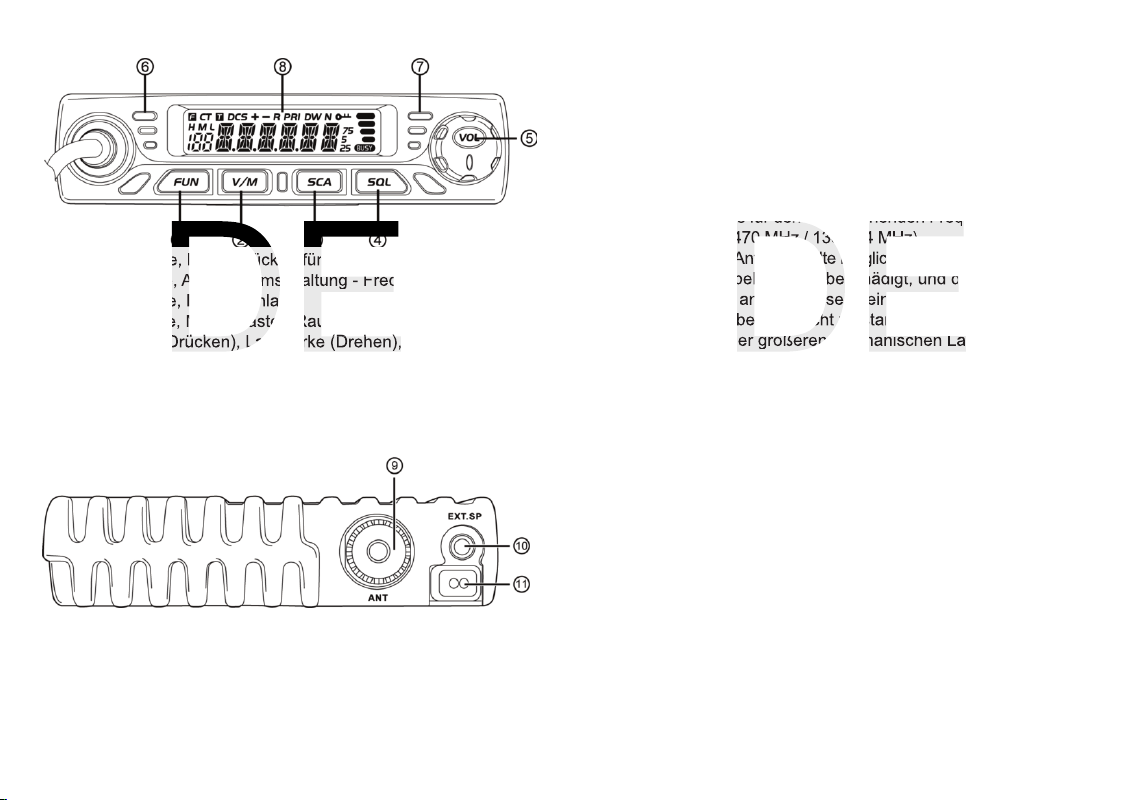
Bedienelemente
1 FUN Taste, lange Drücken für Menü-Aktivierung
2 V/M Taste, Anzeige Umschaltung - Frequenz/Kanal/Name
3 SCA Taste, Kanalsuchlauf
4 SQL Taste, Monitortaste - Rauschsperre wird deaktivert
5 Ein/Aus (Drücken), Lautstärke (Drehen), Menüsteuerung
6 Anzeige rel. Emfangssignalstärke
7 Anzeige rel. Sendesignalstärke
8 LCD Anzeige
9 PL Antennenbuchse
10 3,5 mm Anschlussbuchse für ext. Lautsprecher
11 Stromversorgungskabel
Tastenkombinationen - nacheinander, jeweils kurz Drücken:
CTCSS/DCS : FUN Taste gefolgt von SQL Taste,
mehr Infos siehe CTCSS/DCS
Tastatursperre : FUN Taste gefolgt von Ein/Aus Taste,
mehr Infos siehe Tastatursperre
Kanalsuchlaufliste: FUN Taste gefolgt von SCA Taste, Kanal wird
für Kanalsuchlauf gesperrt/freigegeben.
Page 4
Stromversorgung
Vor dem Anschluss der Stromversorgung schalten Sie das Gerät aus,
indem Sie den Lautstärkeregler (5) [VOL] gedrückt halten bis das
Gerät ausgeschaltet ist.
Verbinden Sie die beiden blanken Anschlüsse am Ende des Kabels mit dem 12 V Bordnetz Ihres Fahrzeuges. Das Stromversor-
gungskabel sollte möglichst weit von störenden Aggregaten verlegt
werden. Achten Sie beim Anschluss auf die richtige Polarität:
SCHWARZ wird mit "-" ( = MINUS / Masse ) des KFZ verbunden.
ROT wird mit "12 Volt +" ( = PLUS ) des KFZ-Bordnetzes verbunden.
Bei Verwendung von Dauerplus bleiben die letzten Einstellungen
auch nach dem Ausschalten des Gerätes und dem Abstellen des Motors gespeichert.
Nachdem die Antenne und die Stromversorgung sorgfältig angeschlossen sind, kann der Funkbetrieb aufgenommen werden.
FUNKBETRIEB
Einschalten [ VOL ]
Zum Einschalten des Gerätes den Lautstärkeregler (5) [Vol ] kurz
drücken. Zum Ausschaltenden Drehregler für ca. 2 Sekunden gedrückt halten.
Rauschsperre [ SQL ]
Der Schwellwert für die Rauschsperre kann am Gerät im Funktionsmenü und via Software-Programmierung auf einer Skala von 1-9 eingestellt werden. Je höher der Wert, desto stärker muss das
Empfangssignal sein um die Rauchsperre zu öffnen.
Für die Änderung der Rauschsperre am Gerät lesen Sie bitte den Abschnitt Funktionsmenü.
Für die Deaktivierung der Rauschsperre ist die Taste SQL (xx) vorgesehen. Per Software kann diese Funktiontaste belegt werden mit der
Funktionsweise Rauschsperre Aus/Ein (Vorbelegung) oder Rausch-
sperre Aus Temporär, d.h. solange wie die Taste gedrückt wird.
Ebenso ist auf eine ordentliche Verbindung des Antennenkabels mit
dem Antennenfuß zu achten. Nicht einwandfreie Verbindungen können zu einem Defekt des Gerätes führen und die Funkreichweite erheblich verringern. Die Antennenanlage (nicht im Lieferumfang
enthalten) sollte sehr gut an das Funkgerät angepasst sein, ansonsten wird ein Teil der Sendeleistung an der Antenne reflektiert und
nicht abgestrahlt. Das führt ebenfalls zu einer geringeren Reichweite
der Funkanlage. Die Anpassung der Antenne erfolgt durch Längenabgleich des Antennenstrahlers bzw. seiner Anpassungsvorrichtung
auf ein minimales Stehwellenverhältnis, welches mit einem Stehwellenmessgerät (z.B. TEAM SWR-PRO VHF/UHF) gemessen werden
kann. Das Stehwellenmessgerät muss nach der Messung wieder aus
der Antennenleitung entfernt werden. Die Anpassung der Stehwelle
kann nur bei den Betriebsfunkvarianten vorgenommen werden.
Montage des Gerätes im Fahrzeug
Das Gerät kann mit dem beiliegenden Montagebügel-Set z.B. unter
dem Armaturenbrett befestigt werden. Bei der Wahl der optimalen
Position für die Montage des Gerätes in Ihrem Fahrzeug sind auch
die folgenden Kriterien zu berücksichtigen:
> keine Beeinträchtigung der Verkehrssicherheit,
> gute Erreichbarkeit der Bedienelemente,
> ausreichende Luftzirkulation, um eine Überhitzung des Gerätes
im Sendefall zu verhindern.
Darüber hinaus sollten Sie auch sicherstellen, dass die LCD-Kanalanzeige (8) gut ablesbar ist. Bei direkter Sonneneinstrahlung kann
die Lesbarkeit der Anzeige beeinträchtigt werden. Die günstigste
Montageposition sollte vor dem endgültigen Einbau überprüft werden. Mit Hilfe des beiliegenden Montagebügels, ist eine schnelle
Montage bzw. Demontage an verschiedenen Stellen im Fahrzeug
möglich.
Mikrofon
Das Mikrofon ist fest mit dem Gerät verbunden. Es ist mit einer Sendetaste (PTT), sowie den Kanalwahltasten UP/DN ausgerüstet.
6
7
Page 5
Tastatursperre [Schlüsselsymbol]
Die Aktivierung der Tastursperre blockiert alle Funktionstasten mit
Ausnahme der Sendetaste. Das Gerät kann nur noch Senden und
Empfangen.
Zum Einschalten bzw. Ausschalten der Tastatursperre drücken Sie
kurz die Funktionstaste FUN (1) - das Symbol F erscheint in der Anzeige - und direkt im Anschluss den Lautstärkeregler.
Der aktive Zustand der Tastatursperre wird durch das Schlüsselsymbol angezeigt.
CTCSS/DCS
Das MiCo verfügt über eine tonsignalgesteuerte Rauschsperre. Hierfür
stehen 51 CTCSS und 777 DCS I/N Kodierungen zur Verfügung.
Für Auswahl der DCS Kodierung am Gerät steht nur die Kodierungsart
N ( Normal) zur Verfügung. Die Auswahl der DCS Kodierungsart I (Inverse, auf deutsch umgekehrt) ist aus Speicherplatzgründen nur per
Software möglich.
Jeder Kanal kann per Software unterschiedlich programmiert werden.
Per Softwareprogrammierung sind Sende- und Empfangsfrequenz unabhängig voneinander kodierbar.
Am Gerät stehen die folgenden Kodierungsmöglichkeiten zur Verfügung. Hinweis: hiervon abweichende Programmierungen per Software werden am Gerät nicht angezeigt.
T : CTCSS-Kodierung nur für Sendefrequenz
CT : CTCSS-Kodierung für Sende- und Empfangsfrequenz
DCS : DCS
Für die CTCSS/DCS Einstellung am Gerät drücken Sie kurz die
Funktionstaste FUN (1) gefolgt von der Rauschsperre-Taste SQL (4).
Durch wiederholtes Drücken der SQL Taste schalten Sie durch alle
Kodierungsmöglichkeiten. Erscheint keines der oberen Symbole in
der Anzeige, ist die Funktion deaktiviert.
Sobald die gewünschte Kodierungsart eingestellt ist, wählt man die
Kodierung mit Hilfe des Lautstärkereglers. Die Auswahlbestätigung
erfolgt automatisch oder durch Drücken der FUN Taste (1).
8
9
Kanalwahl [UP] [DN]
Die Kanalwahl erfolgt durch Drücken der Kanalwahltasten [UP] und
[DN] am Mikrofon. Entsprechend der gewählten Anzeigeart wird die
Kanalnummer, die Frequenz oder der Kanalname, insofern programmiert, angezeigt.
Kanalsuchlauf [SCA]
Durch Drücken der Suchlauf-Taste [SCA] (3) wird der Kanalsuchlauf
gestartet bzw. gestoppt. Im aktiven Zustand werden alle für den Kanalsuchlauf freigegebenen Kanäle solange durchsucht bis ein besetzer Kanal gefunden wird. Dann pausiert die Kanalsuchlauffunktion
solange, bis das Signal endet, Der Suchlauf wird dann fortgesetzt.
Während des aktiven Kanalsuchlaufes ist ein blinkender Punkt in der
Anzeige zu sehen. Wird während des Kanalsuchlaufes die Sendetaste gedrückt, schaltet das Gerät auf den zuletzt besetzten Kanal der
im Suchlauf gefunden wurde. Wurde kein besetzter Kanal gefunden,
schaltet das Gerät auf den Ursprungskanal um, auf dem der Suchlauf
gestartet wurde. Mit Hilfe der optionalen Software T-UP37 kann das
Verhalten der Suchlauffunktion geändert werden.
Durch Drücken der FUN Taste (1) gefolgt von der SCA Taste (3) wird
der Kanal aus der Kanalsuchlaufliste entfernt - angezeigt durch einen
zusätzlichen Punkt in der Anzeige - oder wieder hinzugefügt.
Senden
Zum Senden wird die im Mikrofon eingebaute Sendetaste gedrückt
und für die Dauer der Durchsage gehalten. In dieser Zeit leuchtet das
Sendesignal S-Meter (7) auf der rechten Geräteseite.
Nach Beendigung der Durchsage die Sprechtaste loslassen. Das
Gerät schaltet automatisch in den Empfangsbetrieb zurück. Die Bedienelemente sind während des Sendens gesperrt.
Das Gerät verfügt über eine Sendesperre-Funktion (Tx Off), welche
per Software oder durch das Funktionsmenü (#06 TX) des Gerätes
aktiviert bzw. deaktiviert werden kann.
Empfang
Die relative Empfangssignalstärke wird am linken S-Meter (6) angezeigt.
Abhängig von der Verwendung von CTCSS/DCS, sowie der Rauschsperre Einstellung kann es sein, dass das Signal nicht hörbar ist.
Page 6
Funktion Erklärung verfügbare Einstellungen
03 – bAND Bandbreite NAR/MID/WIDE
In den Versionen PMR und FreeNet ist die Bandbreite auf 12,5 kHz
festgelegt. In den Betriebsfunkversionen stehen die Einstellungen
NAR (12,5 kHz), MID (20 kHz) und HIGH (25 kHz) zur Auswahl.
Es dürfen nur die Werte gemäß der Zulassung von der Bundesnetzagentur programmiert werden.
04 – BUSY Sendesperre auf OFF/bU
besetztem Kanal
Wird im aktivierten Zustand auf einem besetzten Kanal gesendet,
ertönt ein Warnton und in der Anzeige erscheint das Symbol
BUSY.
05 – NAME Kanalname 6 digits, A-Z
Für die 6-stellige Kanalnamen-Programmierung stehen die Buchstaben A-Z, die Zahlen 0-9, sowie der Bindestrich zu Verfügung.
Der jeweils aktive Platzhalter blinkt. Wählen Sie das gewünschte
Symbol durch Drehen des Lautstärkereglers. Durch Drücken der
V/M Taste (2) wird der nächste Platzhalter aktiviert. Durch Drücken
der FUNC Taste (1) kehrt man zurück zur letzten Stelle zurück.
Bestätigen Sie endgültige Auswahl durch Drücken des Kanalwahldrehschalters.
06 – TX Sendebetrieb ON/OFF
Für den aktuell gewählten Kanal kann der Sendemodus mit der
Auswahl OFF deaktiviert werden.
07 – REV Frequenz-Umkehrung ON/OFF
Diese Einstellung ist nur für die Betriebsfunkvarianten relevant.
Bei Verwendung von unterschiedlicher Sende- und Empfangsfrequenz für einen Kanal, werden diese im aktiven Zustand (ON) vertauscht.
08 – TALK Sendefrequenzanpassung ON/OFF
Diese Einstellung ist nur für die Betriebsfunkvarianten relevant.
Bei Verwendung von unterschiedlicher Sende- und Empfangsfrequenz für einen Kanal, wird die Empfangsfrequenz für die Sendefrequenz übernommen.
FUNTIONSMENÜ
Mit Hilfe des Funktionsmenüs können die Geräteeinstellungen geändert
werden. Durch langes Drücken der Funktionsmenü-Taste FUN (1) wird
das Menü geöffnet. In der Anzeige erscheint die Funktionsmenü-Nummer und -Bezeichnung.
Die gewünschte Funktion wird durch Drehen des Lautstärkeregelers
bzw. mit Hilfe der Kanalwahltasten am Mikrofon ausgewählt. Durch
Drücken des Lautstärkeregelers wird die ausgesuchte Funktion für die
Einstellungsänderung aktiviert.
Die gewünschte Einstellung ist wiederum durch Drehen des Lautstärkereglers bzw. mit Hilfe der Kanalwahltasten am Mikrofon einzustellen.
Durch Drücken des Lautstärkereglers wird die Einstellung gespeichert.
Per Software-Programmierung ist es möglich das gesamte Funktionsmenü (01-19) oder Teile der verfügbaren Funktionen für die Einstellung
am Gerät zu blockieren - Softwareprogrammierung Optionalmenü 1-10
/ Kanalmenü 11-19.
Funktion
Erklärung verfügbare Einstellungen
01 – SPK Squelch Modus SQ/CTC
Ist für den Kanal eine Kodierung aktiviert (CTCSS/DCS), kann bestimmt werden ob der Lautsprecher nur öffnet bei gleicher Kodierung (CTC) oder unabhängig von der gewählten Koderierung (SQ).
Ist keine Kodierung für diesen Kanal eingestellt, steht nur die Auswahl SQ zur Verfügung.
02 – POW Sendeleistung LO/MI/HI
In den anmelde- und gebührenfreien Varianten PMR und FreeNet
beträgt die maximale Sendeleistung 500 mW, es steht nur die Sendeleistung LO zur Verfügung.
In den Betriebsfunkausführungen VHF- und UHF-COM können die
Sendeleistungseinstellungen LO (niedrig), MI (middle) und HI am
Gerät (Menüfunktion 02 POW) und per Software für jeden Kanal
ausgewählt werden.
Für die Einstellung der Sendeleistungswerte LO, MI und HI wenden
Sie sich bitte an Ihren Händler. Es dürfen nur die Werte gemäß der
Zulassung von der Bundesnetzagentur programmiert werden.
10
11
Page 7

12
13
Funktion Erklärung verfügbare Einstellungen
09 – SHIFT Frequenzablage Richtung OFF/+/-
Diese Einstellung ist nur für die Betriebsfunkvarianten relevant.
Die für den Relaisbetrieb nötige Sendefrequenz-Verschiebung wird
in der Richtung bestimmt. Der unter dem Funktionsmenüpunkt 10
(OFFSET) eingestellte Frequenzabstand wird unterhalb (-) oder
oberhalb (+) der Empfangsfrequenz angewandt. In der Anzeige erscheint das entsprechende Symbol.
10 – OFFSET Frequenzablage Abstand 0-90 MHz
Diese Einstellung ist nur für die Betriebsfunkvarianten relevant.
Der Abstand der für den Relaisbetrieb nötigen Sendefrequenz-Verschiebung wird im Bereich bis 90 MHz bestimmt. Das Frequenzraster wird mit der Funktion 11 STEP bestimmt.
11 – STEP Frequenzraster 5/6,25/10/12,5/20/25/50 kHz
Diese Einstellung ist nur für die Betriebsfunkvarianten relevant.
Für die Frequenzablage (10 OFFSET) wird das Frequenzraster
bestimmt.
12 – dSP Kanalanzeigeart CH / FREQ / NM
Die Kanalanzeigearten Kanalnummer (CH), Frequenz (FREQ)
oder Kanalname (NM), insofern dieser programmiert wurde, werden umgeschaltet. In den Kanalanzeigearten FREQ und NM ist
die Kanalnummer zusätzlich sichtbar.
13 – bEEP Warnton ON/OFF
Im aktiven Zustand (ON) wird jeder Tastendruck akustisch bestätigt.
14 – TOT Sendezeitbegrenzung OFF/1-30 min
Im aktiven Zustand (1-30 min) wird der Sendebetrieb nach Ablauf
der festgelegten maximalen Sendezeit automatisch abgebrochen.
In den Versionen PMR und FreeNet kann die Sendezeitbegrenzung
nicht abgeschaltet werden, die max. Sendezeit beträgt 3 Minuten.
15 – APO autom. Ausschaltung OFF; 30/60/120 min
Im aktiven Zustand (30/60/120 min) schaltet das Gerät automatisch
nach der gewählten Zeitdauer ab.
Funktion Erklärung verfügbare Einstellungen
16 – SQL Squelch OFF/1-9
Die Rauschunterdrückung bestimmt den Schwellwert der nötigen
Signalstärke für die Freischaltung oder Öffnung des Lautsprechers.
Je höher der gewählte Wert ist desto stärker muss das Signal sein
um die Rauschunterdrückung auszuschalten. Im ausgeschalteten
Zustand (OFF) ist das typische Frequenzrauschen beständig zu
hören.
17 – AOP autom. Einschaltung ON/OFF
Im aktiven Zustand (ON) schaltet das Gerät automatisch beim Einschalten der externen Stromversorgung ein. Dies ist für die Verwendung in Fahrzeugen vorteilhaft wenn das Gerät immer sofort
betriebsbereit sein soll.
18 – MIG Mikrofonempfindlichkeit 1-16
Die Kommunikation mit signalstarken Gegenstationen kann zu
Rückkopplungen führen. In diesem Fall ist das Absenken der Mikrofonempfindlichkeit vorteilhaft. Je höher der Wert desto größer
die Mikrofonempfindlichkeit.
19 – RESET Rückstellung SETUP/FACT
Die Einstellung SETUP setzt die geänderten Geräteeinstellungen
auf die individuelle Softwareprogrammierung zurück, die Frequenzprogrammierung wird beibehalten.
Die Einstellung FACT setzt alle Einstellungen und geänderten Frequenzen auf die werkseitige Programmierung zurück.
Hinweise: eine Datensicherung der individuellen Programmierung
ist empfehlenswert.
Die Rückstellfunktion kann per Softwareprogrammierung deaktiviert werden. Die Einstellungen SETUP und FACT stehen dann
nicht zu Verfügung.
Anschlussbuchse externer Zusatzlautsprecher
An der Rückseite befindet sich die Klinkenbuchse (10) (3,5 mm ø,
mono) zum Anschluss eines ext. Lautsprechers mit 4 - 8 Ohm Impedanz, wie z.B. dem TEAM TS-500. Bei 4 Ohm sollte die Belastbarkeit
des Lautsprechers 4 Watt betragen. Bei Anschluss des externen
Lautsprechers wird der interne Lautsprecher abgeschaltet.
Page 8

HINWEISE
Sicherheitshinweis
Bitte beachten Sie als KFZ-Fahrer beim Funkbetrieb auch die Bestimmungen der jeweils gültigen Straßenverkehrsordnung. Bei dem Betrieb
des Gerätes wird Hochfrequenzenergie freigesetzt. Es muss daher ein
entsprechender Sicherheitsabstand zur Antenne eingehalten werden.
Allgemeine Hinweise
Das Gerät ist vor Feuchtigkeit und Staub zu schützen, niemals an
Orten aufbewahren, die einer starken Erhitzung und/oder direkter Sonneneinstrahlung ausgesetzt sind. Zur Gehäusereinigung ein weiches,
fusselfreies Tuch verwenden, niemals Lösungsmittel verwenden.
Service
Das Gerät darf nicht geöffnet werden. Eigenhändige Reparaturen
oder Abgleich sind nicht vorzunehmen, denn jede Veränderung, bzw.
Fremdabgleich, können zum Erlöschen der Betriebserlaubnis sowie
der Gewährleistungs- und Reparaturansprüche führen. Bei Betriebsstörungen sollte das Gerät nicht benutzt werden. Trennen Sie in diesem Fall die Stromversorgung ab. Liegt ein Defekt vor, sollte auf
jeden Fall der autorisierte TEAM-Fachhändler kontaktiert werden.
Konformität
Das Mobilsprechfunkgerät TEAM MiCo entspricht den europäischen
CE-Richtlinien RED Direktive 2014/53/EU und hält die europäischen
Normen (siehe Konformitätserklärung) ein.
Entsorgung
Bitte werfen Sie Ihr TEAM-Altgerät nicht einfach auf den Müll, sondern
senden Sie Ihr Altgerät bitte portofrei zur fachgerechten Entsorgung an
TEAM ein. TEAM wird anschließend die umweltschonende Entsorgung
Ihres Altgerätes für Sie kostenlos veranlassen. Bitte machen Sie mit der Umwelt zuliebe.
- Änderung der technischen Daten und der Ausführung sind
ohne Vorankündigung vorbehalten. -
14
15
Page 9

16
17
TABLE OF CONTENTS
Elements 18
Setup
Installation of an antenna 19
Aerial Connection 20
Installation in the car 20
Microphone 20
Power source 21
Operation
On / Off [ VOL ]22
Squelch [ SQL ]22
Scan [ A/F ]22
Transmit 22-23
Reception 23
Key lock [ key symbol ] 23
CTCSS/DCS 23
Function Menu 24-27
External speaker jack 27
Additional Information
Safety Instructions 28
General Precautions 28
Servicing 28
Conformity 28
Specifications 29
CTCSS/DCS Codes 30
Dear customer,
Thank you for buying a TEAM MiCo transceiver. TEAM Electronic stands for
high-quality radio communication.
To fully understand the various functions and the possible settings and to ensure the proper operation of the radio, we recommend to read this manual
prior to first time use.
The TEAM MiCo is available in these four versions:
MiCo Freenet - item no. PR8135
programmed with 6 FreeNet** channels, 500 mW tx power, bandwidth
12.5 kHz, no registration or fees apply, only permitted in Germany.
MiCo PMR - item no. PR8134
programmed with 16 PMR* channels, 500 mW tx power, bandwidth
12.5 kHz, no registration or fees apply - see radio passport - antenna is
fixed
MiCo UHF-COM - item no. PR8126
commercial radio; 199 channels programmable; registration and fees
apply; only assigned frequencies and parameters are allowed to be
programmed; max. TX power 4 W; UHF 440 - 470 MHz
MiCo VHF-COM - item no. PR8128
commercial radio; 256 channels programmable; registration and fees
apply; only assigned frequencies and parameters are allowed to be programmed; max. TX power 5 W; VHF 136 - 174 MHz
Program the TEAM MiCo with the additional software T-UP37, which is
available in the versions PMR-FN and COM for Windows 8 / 10. The
software package contains a USB data transfer cable.
* = PMR Frequencies ** = FreeNet Frequencies
01 - 446.00625 MHz 09 - 446.10625 MHz 1 - 149.0250 MHz
02 - 446.01875 MHz 10 - 446.11875 MHz 2 - 149.0375 MHz
03 - 446.03125 MHz 11 - 446.13125 MHz 3 - 149.0500 MHz
04 - 446.04375 MHz 12 - 446.14375 MHz 4 - 149.0875 MHz
05 - 446.05625 MHz 13 - 446.15625 MHz 5 - 149.1000 MHz
06 - 446.06875 MHz 14 - 446.16875 MHz 6 - 149.1125 MHz
07 - 446.08125 MHz 15 - 446.18125 MHz
08 - 446.09375 MHz 16 - 446.19375 MHz
Page 10

SETUP
Installation of a CB antenna
The antenna is one of the most critical parts in the setup. The type
of antenna and its location has a great effect on the range of operation. Please consider the following criteria for selection of the best
location and the installation of your antenna:
> The antenna has to be designed for the according frequency range
(450-470 MHz / 136-174 MHz.
> The position of the antenna should be elevated without any
obstacles nearby.
> The aerial cable should not be damaged and the plugs should be
properly connected.
> Make sure that the antenna cable is not bent.
> The bigger the mechanical size of the antenna, the higher the
range of operation.
Please consider:
> The antenna should be fixed in the center of a big body-part, e.g.
the trunk.
> The mobile antenna coil should have the closest possible contact
with a conducting metallic surface of the bodywork of the car.
There are other possibilities to fix the antenna onto the car without
having to drill a hole into the bodywork of your car, e.g. mounting the
antenna with a antenna holder onto the gutter or the trunk. Magnetic
mount antennas (with an magnetic base) or windshield antennas,
which are glued onto the glass, are also alternatives.
> All connected cables including the antenna cable must not exceed
a length of 4.5 m.
elements
1 FUN key, press long for menu activation
2 V/M key, display type - frequency/channel/name
3 SCA key, scan
4 SQL key, monitor - deactivates squelch
5 on/off (push), volume (turn), menu navigation
6 display relative rx signal strength
7 display relative tx signal strength
8 LCD
9 PL antenna jack
10 3.5 mm jack for external speaker
11 power supply cable
key combination - press shorty, one after the other:
CTCSS/DCS : FUN key followed by the SQL key,
more infos see CTCSS/DCS
key lock : FUN key followed by on/off key,
more infos see key lock
scan list add/del : FUN key followed by SCA key, delete/add the
channel from/to the scan list - deleted channels
are marked with an additional dot in the display.
18
19
Page 11

Aerial Connection
Please note that the antenna of the PMR version is fixed.
Before pressing the transmit key, a suitable aerial must be connected. The PL259 plug of the aerial cable (coax) is connected to
the SO239 socket (8) on the rear panel. Make sure, that all plugs are
firmly tightened and properly soldered. Insufficient connections can
damage the radio and will reduce the range of operation.
The antenna should be configured with the radio, otherwise a part
of the transmit power will be reflected at the antenna and will not be
radiated. This reduces the range of operation. The configuration of
an antenna to a radio, is performed by a length adjustment of the antenna’s radial for a minimal SWR ratio which can be measured by a
SWR meter, e.g. TEAM SWR-PRO UHF/VHF.
After the measurement the SWR meter should be removed from the
antenna line.
Installation in the car
When you want to install the radio in your vehicle, use the included
mounting kit, including the u-bracket. Always mount the transceiver in
a location where the buttons are easily accessible. Other important
points to consider for a correct mounting position are:
> roadworthiness,
> good access to the controls of the car,
> sufficient air circulation to prevent overheating of the radio in
transmit mode.
Please consider your point of view onto the display while driving.
Starting from a certain angle of view, the readability of the display diminishes. An intensive solar irradiation can also affect the readability
of the display. So it is recommended to check the best position before
the final installation.
Microphone
The microphone is fixed to the radio, it cannot be removed. It contains
the PTT key, as well as the channel selectors UP and DOWN.
Power source
Before connecting the unit to a suitable power source via the fused
DC power cable, the device must be switched off by turning the volume control (5) [ VOL ] counterclockwise to the very end, beyond
the threshold, until you hear a click.
Then, connect the two naked leads at the end of the cable with the
supply voltage of the vehicle’s battery. The unit is designed to operate with 12 volts and a negative ground electrical system. Lay the
cable as far as possible away from aggregates which can cause interference. Watch for the correct polarity during the connection.
BLACK connect to - MINUS / ground of the car battery.
RED connect to 12 volts + PLUS of the vehicle’s battery.
After proper connection of the aerial and the power source, radio
operation can be started.
20
21
Page 12

23
OPERATION
On/Off [ VOL ]
To power-on the radio, push the rotary volume control shortly. To turn off
the radio, push the rotary volume control for approximately 2 seconds.
Squelch [ SQ ]
The threshold of the squelch function can be set at the radio or via software on a scale between 1-9. The higher the value, the stronger the signal has to be in order to open the squelch filter.
For changing the squelch level at the radio, please see the paragraph
Function Menu.
To deactivate the squelch, please use the SQL key (4). As long as you
press the key, the squelch is deactivated. Via software this key can be
programmed to a) turn off/on the function by pressing the key or b) to
temporarily deactivate the squelch as long as the key is pushed.
Channel selection [UP] [DN]
User the channel selector keys [UP] and [DN] at the microphone for
channel selection. Depending on the setup, the channel number or
the frequency or the channel name is displayed.
Scan [SCA]
To start/stop the scan function, press the scan key [SCA] (3). When activated, all channels that are enabled for scanning will be searched for
signals until a signal has been detected. Then, the scan function pauses
until the signal ends. Scanning continues after the pause. A blinking dot
in the display indicates the active scan status.
If the PTT key is pushed during scan, the radio will switch to the last
channel where a signal has been received. If no signal has been found
during scanning, the radio will switch back to the starting channel.
With the optional software T-UP37, the scan settings can be changed.
Transmit
For signal transmission, press and hold the PTT key at the microphone.
The signal strength is at the tx s-meter (7). After completion, release
the PTT key and the radio will automatically return to reception mode.
All function keys are blocked during signal transmission.
22
Attention: the radio contains a tx-blockage function, which can be set
in the Function Menu (#06 TX).
Reception
The signal strength of the received signal is indicated at the rx s-meter (6).
Depending on the squelch setting and/or CTCSS/DCS, it could be that
the signal is not audible through the speaker. Please check the according settings if necessary.
Key lock [key symbol]
In active mode, the key lock function will block all function keys, except for the PTT key. To activate/deactivate the key lock function,
press the FUN key (1) first (the letter F will appear in the display) and
then push the rotary volume control. The key symbol in the display
will indicate the active state of the function.
CTCSS/DCS
There are 51 CTCSS codes and 777 DCS codes (N (normal) and I
(inverse)) available. The available codes can be individually assigned
to the different channels.
For the DCS codes, at the radio you can only set the N-codes, The Icodes can only be programmed via the software.
Each channel can be encoded individually. By software, tx and rx frequencies can be set differently. At the radio, the following settings are
available. Differing programming by software are not displayed at the
radio.
T : CTCSS codes only for tx-frequency
CT : CTCSS codes only for rx- and tx-frequency
DCS : DCS
To change or set a CTCSS or DCS code, press the function key FUN
(1) followed by the squelch key SQL (4). By repeatedly pressing the
squelch SQL key (4), the radio switches through the modes T, CT and
DCS. If no symbol appears in the display, no mode is activated.
Once the mode is selected, turn the rotary volume control (5) to select
a code. The selection is stored automatically or by pressing the FUN
key (1).
Page 13

24
25
functions description settings
04 – BUSY busy channel lockout OFF/bU
If activated, transmission is not possible on an occupied channel. A
warn tone is audible and the symbol BUSY appears in the display.
05 – NAME channel name 6 digits, A-Z
A six-digit channel name can be programmed. The available symbols are A-Z, 0-9 and the hyphen.
The active space holder blinks. Make your selection by turning the
rotary volume control (5). Advance to the next digit with the V/M
key (2). To return to the prior digit, use the FUN key (1) you return
to the prior one.
Once finished, confirm your selection by pushing the rotary volume
control (5).
06 – TX transmit mode ON/OFF
For deactivation of the transmission mode on the actual channel,
use the option OFF.
07 – REV frequency reverse ON/OFF
This setting concerns only the commercial versions UHF-/VHFCOM.
When using different frequencies for transmission (tx) and reception (rx), the frequencies will be reversed with the setting ON.
08 – TALK tx-frequency adjustment ON/OFF
This setting concerns only the commercial versions UHF-/VHFCOM. When using different frequencies for transmission (tx) and
reception (rx), the transmission frequency will be set to the reception frequency.
09 – SHIFT frequency shift direction OFF/+/-
This setting concerns only the versions UHF-/VHF-COM.
The, for repeater operation, required frequency shift is defined in
its direction. The under #10 (OFFSET) defined frequency shift will
be applied above (+) or below (-) the reception frequency. The according symbols (+ / -) are displayed.
FUNCTION MENU
With the function menu, the available settings can be changed. To access the menu, press the function key FUN (1) for approximately 2 seconds. The display indicates the function its number.
To navigate through the available functions use the channel selectors
of the microphone or turn the rotary volume control.
To activated the selected funtion for editing, push the rotary volume
control. Then, select the function setting with the channel selectors of
the microphone or by turning the rotary volume control (5) and confirm
by pushing the rotary volume control (5).
Via software programming it is possible to deactivate parts (option 110 / channel 11.19) or even the entire menu. This can be useful if the
administrator does not prefer unwanted setting changes by users.
function
description settings
01 – SPK squelch mode SQ/CTC
With the squelch mode selection CTC, the signal will only be audible if the CTCSS/DCS codes matches. The squelch mode setting SQ does not consider the CTCSS/DCS code and any carrier
on the frequency will be audible.
If no CTCSS/DCS code is selected, SQ is the only available mode.
02 – POW Sendeleistung LO/MI/HI
With the PMR and FreeNet versions, the maximum tx-power is limited to 500 mW due to governmental regulations. The only avaiable setting is LO (low).
For the commercial versions UHF- and VHF-COM, the tx-power
settings LO (low) MI (middle) and HI (high) are available.
For programming of the tx-power values, contact your dealer. The
tx-power setup should only be performed by an authorized service
personnell and in compliance with the individual registration.
03 – bAND bandwidth NAR/MID/WIDE
Due to regulations, for the versions PMR and FreeNet, the only
available bandwidth is 12.5 kHz (NAR). For the COM versions NAR
(12.5 kHz), MID (20 kHz) and WIDE (25 kHz) are available.
Page 14

27
functions description settings
17 – AOP automatic power-on ON/OFF
In active state (ON), the radio powers on automatically once
power is applied.
This feature is useful if the radio should automatically be in operation mode once the vehicle is powered on.
18 – MIG microphone sensitivity 1-16
The communication with stations that transmit very strong signals
can cause feedback. In this scenario it is advantageous to reduce
the microphone sensitivity. The higher the value, the higher the
sensitivity.
19 – RESET default settings SETUP/FACT
The selection SETUP resets all settings to the individual software
programming.
The setting FACT resets all settings to the factory preset.
This feature can be deactivated by software. If deactivated the
settings SETUP and FACT are not offered any more.
Please make a data back-up of your individual programming.
External speaker jack
The MiCo is equipped with a 3.5 mm socket (9) at the rear panel to connect an external speaker of 4-8 ohm impedance, e.g. TEAM TS-500.
At 4 ohms, the speaker load can be 4 watts. When the external speaker
is connected, the internal speaker is muted.
functions description settings
10 – OFFSET frequency shift 0-90 MHz
This setting concerns only the commercial versions UHF-/VHFCOM.
The, for repeater operation, required tx-frequency shift is set in a
range between 0-90 MHz. The frequency steps can be changed
- 5/6.25/10/12.5/20/25/50 kHz.
11 – STEP frequency resolution
5/6.25/10/12.5/20/25/50 kHz
This setting is only of importance for the commercial radio version.
It defines the frequency resolution for the frequency shift.
12 – dSP channel display modes CH / FREQ / NM
The available display modes are channel number (CH), frequency
(FREQ) or channel name (NM) (if programmed).
With the selections FREQ and NM, the channel number is additionally shown.
13 – bEEP warning tone ON/OFF
In active state (ON), every key operation is confirmed with an
acoustic signal, i.e. beep tone.
14 – TOT time-out-timer OFF/1-30 min
In active state (1-30 min), the transmission is automatically deactivated upon expiration of the set TOT time. With the PMR and
FreeNet Version, the TOT time is limited to 180 seconds due to regulations.
15 – APO automatic power-off OFF; 30/60/120 min
In active state (30/60/120 min), the radio automatically powers off
after expiration of the selected time.
16 – SQL squelch OFF/1-9
The squelch level determines the threshold for the required signal
strength to be audible in the speaker. The higher the value, the
stronger the signal has to be in order to pass the filter.
If the squelch is off, the typical, constant frequency noise is audible.
26
Page 15

28
29
Additional information
Safety instruction
Drivers must obey traffic rules regarding the use of transceivers in a
vehicle. The unit radiates RF energy in transmit mode. Please be
aware about the safety distance to the antenna.
General precautions
Protect the mobile radio from humidity and dust.
Do not expose the radio to direct sunlight and other sources of heat.
The radio can be cleaned by wiping with a soft cloth. Do not use
chemical products for cleaning.
Servicing
The device must not be opened. Independent repairs or modifications
must not be performed, it will forfeit warranty and repair claims.
Do not use the mobile radio if it seems not to function correctly. Disconnect the radio from the DC power source immediately. If there is
a defect, the authorized TEAM specialist dealer or TEAM must be
contacted immediately.
Conformity
The CB mobile transceiver TEAM MiCo complies to the European CE
directive 2014/53/EU and meets the European standards as stated in
the Declaration of Conformity..
The specific regulations of the different versions in the different european countries can be found in the radio passport that is included in
this manual.
- specifications are subject to change without any prior notice -
Page 16

51 CTCSS (Hz)
62.5
67.0 94.8 131.8 171.3 203.5
69.3 97.4 136.5 173.8 206.5
71.9 100.0 141.3 177.3 210.7
74.4 103.5 146.2 179.9 218.1
77.0 107.2 151.4 183.5 225.7
79.7 110.9 156.7 186.2 229.1
82.5 114.8 159.8 189.9 233.6
85.4 118.8 162.2 192.8 241.8
88.5 123.0 165.5 196.6 250.3
91.5 127.3 167.9 199.5 254.1
D023
D025
D026
D031
D032
D036
D043
D047
D051
D053
D054
D065
D071
D072
D073
D074
D114
D115
D116
D122
D125
D131
D132
D134
D143
D145
D152
D155
D156
D162
D165
D172
D174
D205
D212
D223
D225
D226
D243
D244
D245
D246
D251
D252
D255
D261
D263
D265
D266
D271
D274
D306
D311
D315
D325
D331
D332
D343
D346
D351
D356
D364
D365
D371
D411
D412
D413
D423
D431
D432
D445
D446
D452
D454
D455
D462
D464
D465
D466
D503
D506
D516
D523
D526
D532
D546
D565
D606
D612
D624
D627
D631
D632
D645
D654
D662
D664
D703
D712
D723
D731
D732
D734
D743
D754
210 DCS N/I
30
31
Page 17

TEAM MiCo for sale and use in:
V2 08-17
UHF- / VHF COM:
AT, BG, CH, CY, CZ, DE, DK, EE, ES, FI, FR, GB, GR,
HU, IE, IT*, LT, LU, NL, NO, PL, PT, RO, SE, SI, SK
PMR / FreeNet:
DE (Deutschland / Germany)
TEAM Electronic GmbH
Austria Germany
Klessheimer Allee 47 Bolongarostrasse 88
A-5020 Salzburg D-65929 Frankfurt/Main
phone ++43 / 662 / 840129 phone ++49 / 69 / 300 950 0
fax ++43 / 662 / 84 05 06 fax ++49 / 69 / 31 43 82
www.team-electronic.at www.team-electronic.de
teamaustria@aol.com team-electronic@t-online.de
WEEE - Reg. Nr. DE 91930360 8 ( EAR ), 50635 ( ERA )
DSD 2617305, ARA 2284
 Loading...