

Page 1
Bedienungsanleitung
Operating Instruction
Manual de Instrucción
Manuale d’istruzioni
Mode d’emploi
Handleiding
- Full Multi Norm
DE / PL / EC / EI / UK
- hp
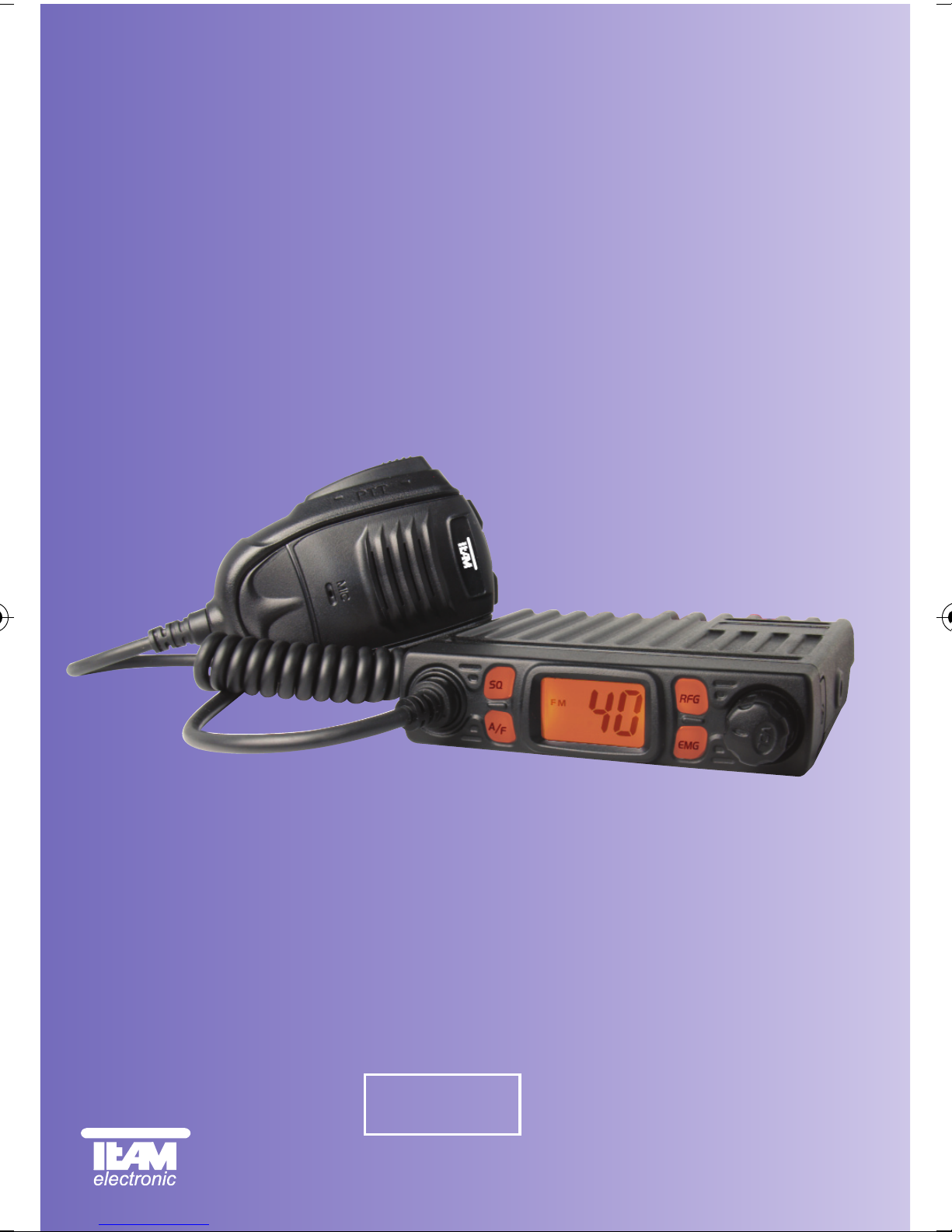
CB Mobile MiniCom
CB-Mobilfunkgerät
CB Mobile Radio
Transmisor móvil CB
Cb émetteur récepteur
Ricetrasmettitori
CB mobile zender
12 Volt
Page 2
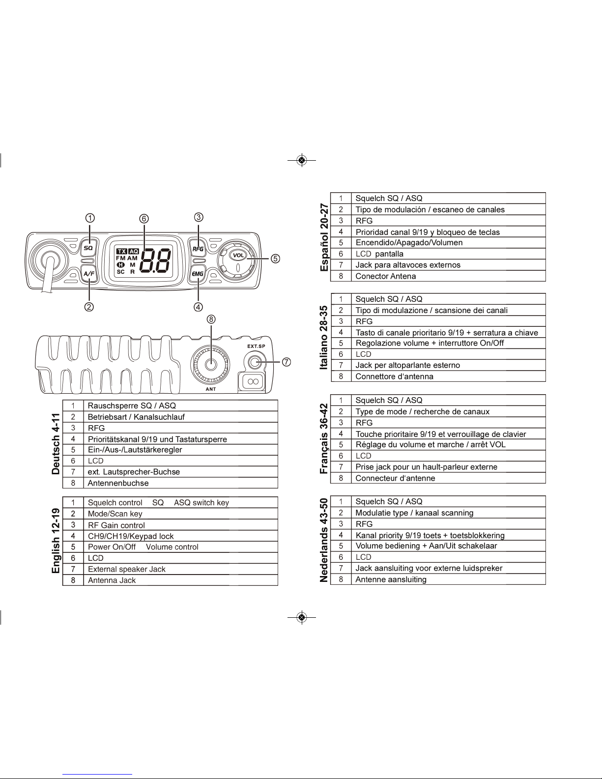
Bedienelemente - elements - éléments -
elementen - elementos - elementi
2
3
manual_cb-mobile-minicom5:Layout 1 11/11/2014 9:42 AM Page 2
Page 3
INBETRIEBNAHME
Montage einer CB-Funkantenne
Die Wahl der Antenne und des Montageortes ist von großer Bedeutung für die maximale Reichweite Ihrer Funkanlage. Die folgenden
Kriterien sollten Sie bei der Wahl des Antennenstandortes und der
Montage berücksichtigen.
Allgemein gilt:
> Die Antenne muss für den Funkbetrieb auf 27 MHz geeignet sein.
> Der Standort der Antenne sollte möglichst hoch und unverbaut sein.
>Das Antennenkabel muss unbeschädigt, und die Stecker
ordnungsgemäß angeschlossen sein.
> Das Antennenkabel darf nicht zu stark geknickt werden.
> Antennen mit einer größeren mechanischen Länge erzielen
bessere Reichweiten.
Bei der Montage von Mobilantennen ist folgendes zu beachten:
> Die Antenne sollte in der Mitte eines größeren Karosserieteils
montiert werden.
> Der Antennenfuß von Mobilantennen sollte besten Kontakt
zu einer metallisch gut leitenden Fläche des Karosseriebleches
haben.
Außer der "festen Montage" einer Mobilantenne, bei der ein Loch in
die Karosserie Ihres Fahrzeuges gebohrt werden muss, gibt es noch
weitere Möglichkeiten, z. B. die Dachrinnen- oder KofferraumdeckelMontage, sowie die Befestigung mit Magnetfuß oder Scheibenantenne.
> Alle angeschlossenen Leitungen, einschließlich der Antennenlei-
tung, dürfen nur eine Länge von max. 4,5 Metern haben.
Antennenanschluss
Der PL-Stecker (Typ PL259) des Antennenkabels (Koaxialkabel) wird
mit der Buchse (8) an der Geräterückseite verbunden. Für eine einwandfreie Verbindung muss der Überwurf des Steckers gut festgedreht werden.
INHALTSVERZEICHNIS
Elemente 2
Inbetriebnahme
Montage einer CB-Funkantenne 5
Antennenanschluss 5 - 6
Montage des Gerätes im Fahrzeug 6
Mikrofon 6
Stromversorgung 7
Funkbetrieb
Einschalten [ Vol ]7
Rauschsperre [ SQ / ASQ ] 7 - 8
Kanalwahl [ UP ] [ DN ]8
Umschaltung der Modulationsarten [A/F]8
Kanalsuchlauf [A/F]8
Umschaltung der Normen 8 - 9
Senden 9
Vorrangkanal 9/19 [ EMG ] 9
Tastatursperre [ EMG ]9
Empfangsempfindlichkeit [ RFG ]10
Anschlussbuchse für ext. Zusatzlautsprecher 10
Hinweise
Sicherheitshinweis 11
Allgemeine Hinweise 11
Service 11
Konformität 11
Entsorgung 11
Kanalfrequenztabelle 51
Technische Daten 27
4
5
manual_cb-mobile-minicom5:Layout 1 11/11/2014 9:42 AM Page 4
Page 4

Stromversorgung
Vor dem Anschluss der Stromversorgung schalten Sie das Gerät aus,
indem Sie den Lautstärkeregler (5) [VOL] bis zum Einrasten nach
links drehen.
Verbinden Sie die beiden blanken Anschlüsse am Ende des Kabels mit dem 12 V Bordnetz Ihres Fahrzeuges. Das Stromversor-
gungskabel sollte möglichst weit von störenden Aggregaten verlegt
werden. Achten Sie beim Anschluss auf die richtige Polarität:
SCHWARZ wird mit "-" ( = MINUS / Masse ) des KFZ verbunden.
ROT wird mit "12 Volt +" ( = PLUS ) des KFZ-Bordnetzes verbunden.
Bei Verwendung von Dauerplus bleiben die letzten Einstellungen
auch nach dem Ausschalten des Gerätes und dem Abstellen des Motors gespeichert.
Nachdem die Antenne und die Stromversorgung sorgfältig angeschlossen sind, kann der Funkbetrieb aufgenommen werden.
FUNKBETRIEB
Einschalten [ VOL ]
Zum Ein- bzw. Ausschalten den Lautstärkeregler (5) [Vol] nach rechts
bzw. nach links drehen.
Rauschsperre [ SQ ]
Das Gerät verfügt über eine automatische (ASQ) und eine manuelle
Rauschsperre (SQ). Beide Schwellwerte können eingestellt werden.
SQ Rauschunterdrückung (O.F. - 2.8)
Nach kurzem Drücken der SQ-Taste (1) erscheint in der Anzeige Sq
gefolgt vom dem aktuellen Wert (O.F. (Aus) - 2.8). Stellen Sie den gewünschten Wert mit Hilfe der Kanalwahltasten am Mikrofon ein.
ASQ Rauschunterdrückung (A.1 - A.9)
Die ASQ Rauschunterdrückung aktivieren Sie durch langes Drücken
der SQ-Taste (1). Der aktive Zustand wird durch das Symbol AQ ange-
zeigt. Der aktuelle Wert (A.1 - A.9) erscheint nur kurz nach dem Drücken
der Taste. Es ist möglich den Wert mit Hilfe der Kanalwahltasten am
Ebenso ist auf eine ordentliche Verbindung des Antennenkabels mit
dem Antennenfuß zu achten. Nicht einwandfreie Verbindungen können zu einem Defekt des Gerätes führen und die Funkreichweite erheblich verringern. Die Antennenanlage (nicht im Lieferumfang
enthalten) sollte sehr gut an das Funkgerät angepasst sein, ansonsten wird ein Teil der Sendeleistung an der Antenne reflektiert und
nicht abgestrahlt. Das führt ebenfalls zu einer geringeren Reichweite
der Funkanlage. Die Anpassung der Antenne erfolgt durch Längenabgleich des Antennenstrahlers bzw. seiner Anpassungsvorrichtung
auf ein minimales Stehwellenverhältnis, welches mit einem Stehwellenmessgerät (z.B. TEAM SWR 1180 P) gemessen werden kann.
Das Stehwellenmessgerät muss nach der Messung wieder aus der
Antennenleitung entfernt werden.
Montage des Gerätes im Fahrzeug
Das Gerät kann mit dem beiliegenden Montagebügel-Set z.B. unter
dem Armaturenbrett befestigt werden. Bei der Wahl der optimalen
Position für die Montage des Gerätes in Ihrem Fahrzeug sind auch
die folgenden Kriterien zu berücksichtigen:
> keine Beeinträchtigung der Verkehrssicherheit,
> gute Erreichbarkeit der Bedienelemente,
> ausreichende Luftzirkulation, um eine Überhitzung des Gerätes
im Sendefall zu verhindern.
Darüber hinaus sollten Sie auch sicherstellen, dass die LCD-Kanalanzeige (6) gut ablesbar ist. Bei direkter Sonneneinstrahlung kann
die Lesbarkeit der Anzeige beeinträchtigt werden. Die günstigste
Montageposition sollte vor dem endgültigen Einbau überprüft werden. Mit Hilfe des beiliegenden Montagebügels, ist eine schnelle
Montage bzw. Demontage an verschiedenen Stellen im Fahrzeug
möglich.
Mikrofon
Das Mikrofon ist fest mit dem Gerät verbunden. Es ist mit einer Sendetaste (PTT), sowie den Kanalwahltasten Hoch/Runter ausgerüstet.
6
7
manual_cb-mobile-minicom5:Layout 1 11/11/2014 9:42 AM Page 6
Page 5
Zum Einstellen bzw. Umschalten der Normen halten Sie bitte den Betriebsarten-Umschalter (2) [A/F] während dem Einschalten des Gerätes gedrückt. In der Anzeige erscheint das Kürzel der aktuellen Norm.
Die gewünschte Norm wird mit Hilfe der Kanalwahl-Taste am Mikrofon
eingestellt. Zum Bestätigen der Norm das Gerät kurz aus- und wieder
einschalten.
Für die Erlaubnis und die Auflagen zum Betrieb der verschiedenen Normen in den einzelnen Ländern sehen Sie in den Gerätepass. Der Benutzer ist für die richtige Einstellung der gültigen
Norm im jeweiligen Land eigenverantwortlich.
Hinweis: Die Ausführung CB Mobile MiniCom hp (Mono Band)
ist fest auf 40 Kanäle AM/FM, 4 Watt/4 Watt eingestellt.
Senden
Zum Senden wird die im Mikrofon eingebaute Sendetaste gedrückt und
für die Dauer der Durchsage gehalten. In dieser Zeit leuchtet das TXSymbol in der Anzeige. Nach Beendigung der Durchsage die Sprechtaste
loslassen. Das Gerät schaltet automatisch in den Empfangsbetrieb zurück. Die Bedienelemente sind während des Sendens gesperrt.
Vorrangkanal 9/19 [EMG]
Das Gerät verfügt über die Vorrangkanäle 9 und 19. Einmaliges Drükken der Vorrangkanaltaste (4) [EMG] aktiviert Kanal 9. Erneutes
Drücken schaltet auf Kanal 19. Drücken Sie die Taste noch einmal,
schaltet das Gerät wieder in den ursprünglichen Kanal um.
Tastatursperre [EMG]
Durch langes Drücken der EMG-Taste (4) wird die Tastatursperre aktiviert. In der Anzeige erscheint kurzzeitig das Symbol LC. Bis auf
den kombinierten Ein-/Ausschalter, sowie der Sendetastetaste am
Mikrofon sind alle anderen Bedienelemente gesperrt.
8
9
Mikrofon zu ändern. Nach kurzer Zeit erscheint in der Anzeige der aktuelle Kanal. Um den ASQ-Wert anzuzeigen genügt ein kurzes Drücken
der SQ-Taste (1).
Hinweis: Je höher der Wert, desto stärker muss das Empfangssignal
sein um die Rauchsperre zu deaktivieren.
Kanalwahl [UP] [DN]
Die Kanäle können durch Drücken der Kanalwahltasten [UP] und [DN]
am Mikrofon eingestellt werden. In der LCD Anzeige ( 6 ) wird die Kanalnummer dargestellt.
Umschaltung der Modulationsarten [A/F]
Das CB Mobile MiniCom arbeitet in den Modulationsarten AM und FM.
In der Full Multi Norm EC steht nur die Betriebsart FM zur Verfügung.
Falls das Gerät auf dem aktuellen Kanal auch die Betriebsart AM akzeptiert, können Sie durch Drücken der Taste (2) [ A/F ] zwischen AM
und FM umschalten.
In der Norm UK schaltet das Gerät zwischen den FM-Frequenzbändern
EC oder UK um. Die Norm UK verfügt über 40 Kanäle FM UK (27,6012527,99125 MHz) und 40 Kanäle FM EC (26,965-27,405 MHz).
Kanalsuchlauf [A/F]
Durch langes Drücken der Taste [A/F] (2) wird der Kanalsuchlauf aktiviert. In der Anzeige erscheint das Symbol SC und alle Kanäle des
gewählten Frequenzbandes werden solange durchsucht bis ein besetzer Kanal gefunden wird.
Umschaltung der Normen
Die Geräteversion CB Mobile MiniCom Full Multi Norm kann vom
Benutzer auf eine der folgenden Normen eingestellt werden:
Norm
Kanäle und Frequenzen
DE 80 FM (26,565-27,405 MHz), 4 W/40 AM (26,965-27,405 MHz), 4W
UK 40 FM (27,60125-27,99125 MHz), 4 W/40 FM (26,965-27,405 MHz), 4 W
EI 40 FM (26,965-27,405 MHz), 4 W/40 AM (26,965-27,405 MHz), 4 W
EC 40 FM (26,965-27,405 MHz), 4 W
PL 40 FM (26,960-27,400 MHz), 4 W/40 AM (26,960-27,400 MHz), 4 W
manual_cb-mobile-minicom5:Layout 1 11/11/2014 9:42 AM Page 8
Page 6
HINWEISE
Sicherheitshinweis
Bitte beachten Sie als KFZ-Fahrer beim Funkbetrieb auch die Bestimmungen der jeweils gültigen Straßenverkehrsordnung. Bei dem Betrieb
des Gerätes wird Hochfrequenzenergie freigesetzt. Es muss daher ein
entsprechender Sicherheitsabstand zur Antenne eingehalten werden.
Allgemeine Hinweise
Das Gerät ist vor Feuchtigkeit und Staub zu schützen, niemals an
Orten aufbewahren, die einer starken Erhitzung und/oder direkter Sonneneinstrahlung ausgesetzt sind. Zur Gehäusereinigung ein weiches,
fusselfreies Tuch verwenden, niemals Lösungsmittel verwenden.
Service
Das Gerät darf nicht geöffnet werden. Eigenhändige Reparaturen
oder Abgleich sind nicht vorzunehmen, denn jede Veränderung, bzw.
Fremdabgleich, können zum Erlöschen der Betriebserlaubnis sowie
der Gewährleistungs- und Reparaturansprüche führen. Bei Betriebsstörungen sollte das Gerät nicht benutzt werden. Trennen Sie in diesem Fall die Stromversorgung ab. Liegt ein Defekt vor, sollte auf
jeden Fall der autorisierte TEAM-Fachhändler kontaktiert werden.
Konformität
Das CB-Mobilsprechfunkgerät TEAM CB Mobile MiniCom entspricht
der europäischen R&TTE Direktive und hält die europäischen Normen EN 300 135-1/-2, EN 300 433-2, EN 301 489-1/-13 und EN
60950-1 ein. Die genauen Länderbestimmungen der verschiedenen
Versionen entnehmen Sie bitte dem beiliegenden Gerätepass.
Entsorgung
Bitte werfen Sie Ihr TEAM-Altgerät nicht einfach auf den Müll, sondern
senden Sie Ihr Altgerät bitte portofrei zur fachgerechten Entsorgung an
TEAM ein. TEAM wird anschließend die umweltschonende Entsorgung
Ihres Altgerätes für Sie kostenlos veranlassen. Bitte machen Sie mit der Umwelt zuliebe.
- Änderung der technischen Daten und der Ausführung sind
ohne Vorankündigung vorbehalten. -
Empfangsempfindlichkeit [RFG]
Signale, die aus unmittelbarer Nähe empfangen werden, können unter
Umständen zu stark sein - das Signal verzerrt.
Mit der RFG-Funktion [ RFG ] ( 3 ) wird die Empfangssignalstärke reduziert durch Schwächung der Empfangsempfindlichkeit. Im aktiven
Zustand erscheint der Buchstabe R in der Anzeige. Nach dem Drücken
der RFG-Taste erscheint der aktuelle Wert (6/12/18/24/30/36/42/48/54
dBm Dämpfung) blinkend in der Anzeige. Mit Hilfe der Kanalwahltasten
am Mikrofon kann der gewünschte Wert angepasst werden.
Anschlussbuchse für einen externen Zusatzlautsprecher
An der Rückseite befindet sich die Klinkenbuchse (7) (3,5 mm ø) zum
Anschluss eines ext. Lautsprechers mit 4 - 8 Ohm Impedanz, wie z.B.
dem TEAM TS-500. Bei 4 Ohm sollte die Belastbarkeit des Lautsprechers 4 Watt betragen. Bei Anschluss des externen Lautsprechers
wird der interne Lautsprecher abgeschaltet.
10
11
manual_cb-mobile-minicom5:Layout 1 11/11/2014 9:42 AM Page 10
Page 7
SETUP
Installation of a CB antenna
The antenna is one of the most critical parts in the setup. The type
of antenna and its location has a great effect on the range of operation. Please consider the following criteria for selection of the best
location and installation of your antenna:
> Make sure that the antenna is designed for radio operation on 27 MHz.
> The location of the antenna should be as high as possible without
any obstacles nearby.
> The aerial cable should not be damaged and the plugs should be
properly connected.
> Make sure that the antenna cable is not bent.
> The bigger the mechanical size of the antenna, the higher the
range of operation.
When you install a mobile antenna please note the following advices:
> The antenna should be fixed in the center of a big body-part, e.g.
the trunk.
> The mobile antenna coil should have the closest possible contact
with a conducting metallic surface of the bodywork of the car.
There are also some other possibilities to fix the antenna onto the
car without the necessity to drill a hole into the bodywork of your car,
e.g. mounting the antenna onto the gutter, mounting the antenna
onto a holder on the cover of the boot or using an antenna with a
magnetic foot or using a windscreen antenna.
> Please don't mount the CB antenna nearby a radio or TV antenna
to prevent interference of radio or TV reception.
> Keep an eye on power lines running along nearby when mounting
the antenna on the roof.
" DANGER "
> All connected cables including the antenna cable must not exceed
a length of 4.5 m.
12
13
TABLE OF CONTENTS
Elements 2
Setup
Installation of a CB antenna 13
Aerial Connection 14
Installation in the car 14
Microphone 14
Power source 15
Operation
On / Off [ VOL ]16
Squelch [ SQ / ASQ ] 16
Channel selection [ UP ] [ DN ]16
Modulation selection [ A/F ] 16 - 17
Scan [ A/F ]17
Norm selection 17
Transmitting 18
Priority Channels 9 / 19 [ EMG ]18
Key lock [ EMG ]18
Receipt-Signal Sensitivity [ RFG ]18
External speaker jack 18
Additional Information
Safety Instructions 19
General Precautions 19
Servicing 19
Conformity 19
Channel Frequencies 51
Specifications 27
manual_cb-mobile-minicom5:Layout 1 11/11/2014 9:42 AM Page 12
Page 8
Power source
Before connecting the unit to a suitable power source via the fused
DC power cable, the device must be switched off by turning the volume control (5) [ VOL ] counterclockwise to the very end until a clikking sound is heard.
Then, connect the two naked leads at the end of the cable with the
supply voltage of the vehicle battery. The unit is designed to operate
with 12 volts and a negative ground electrical system. Lay the cable
as far as possible away from aggregates which can cause interference. Watch for the correct polarity during the connection.
BLACK connect to - MINUS / ground of the car battery.
RED connect to 12 volts + PLUS of the vehicle’s battery.
If the cable is not disconnected from the power source, the last settings
will remain stored after the radio and the car are switched off.
After proper connection of the aerial and the power source, radio
operation can be started.
Aerial Connection
Before pressing the transmit key, a suitable aerial must be connected. The PL259 plug of the aerial cable (coax) is connected to
the SO239 socket (8) on the rear panel. Make sure, that all plugs are
firmly tightened and properly soldered. Insufficient connections can
damage the radio and will reduce the range of operation.
The antenna should be matched with the radio, otherwise a part of
the transmit power will be reflected at the antenna and will not be radiated. This reduces the range of operation. The matching of antenna
to radio, is performed by a length adjustment of the antenna radial
in aim for a minimal SWR ratio which can be measured by a SWR
meter, e.g. TEAM SWR 1180P. After the measurement the SWR
meter should be removed from the antenna line.
Installation in the car
When you want to fix the unit in your car, you can either fasten it with
the help of the included mounting bracket below the dashboard. Always
mount the transceiver where the switches are easily accessible. Other
important points to consider for a correct mounting position are:
> no interference of the roadworthiness,
> good access to the controls of the car,
> sufficient air circulation to prevent overheating of the radio in
transmit mode.
Please consider the perspective onto the display while driving. Starting from a certain angle of view, the readability of the display diminishes. An intensive solar irradiation can also affect the readability
of the display. So it is recommended to check the best position before
the final installation. The unit can easily be fixed onto different positions in the car by using the enclosed mounting bracket.
Microphone
The microphone is permanently connected to the radio, it cannot be removed. It contains the PTT key, as well as the channel selectors UP and
DOWN.
14
15
manual_cb-mobile-minicom5:Layout 1 11/11/2014 9:42 AM Page 14
Page 9
16
17
The selected modulation type is indicated by the AM/FM symbol. To
toggle between the modes press the mode key (2) [A/F].
With the norm UK of the Full Multi Norm, you toggle between the EC
band and the UK band by pressing the mode key (2) [A/F]. The CB
band EU consists of the 40 CEPT channels. The CB band UK consists of 40 channels starting from 27.60125 MHz to 27.99125 MHz.
Scan [A/F]
Pressing the A/F key for approximately 1 second will activate the
channel scan, indicated by the symbol SC in the display. The current
frequency band will be scanned until a signal has been detected.
Norm Selection
The version Full Multi Norm can be set by the user to the following
norms:
DE 80 FM (26.565-27.405 MHz), 4 W / 40 AM (26.965-27.405 MHz), 4 W
EC 40 FM (26.965-27.405 MHz), 4 W
UK 40 FM (27.60125-27.99125 MHz), 4 W/40 FM (26.965-27.405 MHz), 4 W
PL 40 FM (26.960-27.400 MHz), 4 W / 40 AM (26.960-27.400 MHz), 4 W
EI 40 FM (26.965-27.405 MHz), 4 W / 40 AM (26.965-27.405 MHz), 4
For changing the current norm, please hold the mode key (2) [A/F]
while turning the radio on. The current norm appears in the display.
Use the channel selectors UP and DN of the microphone to set a different norm and confirm your selection by turning the radio off and
on again.
Regarding the permissions and restrictions of the individual norms in
the various european countries, please check the radio passport,
which is included in the scope of delivery. The user is solely responsible for the selection of the permissible norm in the country of operation.
Note: the radio mono band version hp operates on 40 FM, 4 W /
40 AM, 4 W only.
OPERATION
On/Off [ VOL ]
To turn on/off the radio, turn the volume switch (5) [VOL]
clockwise/counterclockwise over the threshold.
Squelch [ SQ ]
The radio is equipped with an automatic (ASQ) and a manual squelch
(SQ). Both can be adjusted.
SQ Squelch (O.F. - 2.8)
After shortly pressing the SQ key (1), the symbol Sq followed by actual
setting (O.F. - 2.8) is displayed. Change the according value with the
channel selector keys UP and DN at the microphone.
ASQ Squelch (A.1 - A.9)
The ASQ squelch is activated by a long press of the SQ key (1). The
symbol AQ is displayed. The present value (A.1 - A.9) appears only
shorty after pressing the SQ key. During this short time, you can adjust
the setting with the channel selectors UP and DN of the microphone.
After a short period the channel number will appear. To return to the
squelch setting mode, press the SQ key (1) shortly.
Note: The higher the value of the squelch setting, the stronger the signal
has to be in order to deactivate the squelch.
Channel selection [ UP ] [ DN ]
All channels can be selected by pushing the channel selector keys
[UP] and [DN] at the microphone. The selected channel is displayed
on the LCD (6).
For communication with a partner CB station, both transceivers must
be adjusted to the same channel and the same modulation type.
Modulation selection [A/F]
For the CB Mobile MiniCom Full Multi Norm, the operating modes
AM and FM are available. However, the norm EC of the the version
Full Multi Norm operates in FM only.
manual_cb-mobile-minicom5:Layout 1 11/11/2014 9:42 AM Page 16
Page 10

18
19
Additional information
Safety instruction
Drivers must obey traffic rules regarding the use of transceivers in a
vehicle. The unit radiates RF energy in transmit mode. Please keep
an eye on safety distance to the antenna.
General precautions
Protect the mobile radio from humidity and dust. Do not store at
places where the temperature may rise and cause damage, for example in the sun. The radio can be cleaned by wiping with a soft cloth.
Do not use chemical products for cleaning.
Servicing
The device must not be opened. Independent repairs or adjustment
must not be carried out, since each modification or unauthorized intervention will result in withdrawal of the operation permit and of warranty and repair claims. Do not use the mobile radio if it seems not to
function correctly. Disconnect the radio from the DC power source
immediately. If there is a defect, the authorized TEAM specialist
dealer or TEAM must be contacted immediately.
Conformity
The CB mobile transceiver TEAM CB Mobile MiniCom complies to the
European directive R&TTE and meets the European standards EN 300
135-1/-2, EN 300 433-2, EN 301 489-1/-13 and EN 60950-1.
The specific regulations of the different versions in the different european countries can be found in the radio passport that is included in
this manual.
- specifications are subject to change without any prior notice -
Transmitting
To transmit, press and hold the PTT key at the microphone. The TX
symbol appears in the LCD.
For best quality, speak normally at a distance of 2 - 4 inches. Speaking too
loudly will cause distortion and makes the signal difficult to understand.
While the set is in the transmit mode there is no key entry possible and
the receiver is muted.
On completion of the transmission release the PTT key and the radio
will switch back to receiving mode.
Priority Channel 9 / 19 [EMG]
To switch to priority channel 9 press the EMG key (4) once. To quickly
get to priority channel 19 press the EMG key (4) twice. And to return
to the originally selected channel, press the EMG key one more time.
Key lock [EMG]
Pressing the EMG key for approximately 1 second will activate/deactivate the key lock. The symbol LC will be displayed shortly. Except
for the PTT key and the combined volume and on/off control, all elements are blocked.
Receipt-Signal Sensitivity [RFG]
Signals received from immediate proximity may be too strong, they will
be received distorted.
With the RFG control [RFG] (3), the strength of the received signal
will be diminished by reducing the receivers sensitivity. In active RFG
mode the letter R is displayed.
After pressing the RFG key (3), the actual value is displayed, i.e.
6/12/18/24/30/36/42/48/54 dBm. During this short period the value can
be changed with the channel selector key UP and DN at the microphone.
External speaker jack
The CB Mobile MIniCom is equipped with a 3.5 mm socket (7) at the
rear panel to connect an external speaker of 4 - 8 ohm impedance,
e.g. TEAM TS-500. At 4 ohms the speaker load can be 4 watts. When
the external speaker is connected, the internal speaker will be
switched off.
manual_cb-mobile-minicom5:Layout 1 11/11/2014 9:42 AM Page 18
Page 11

20
21
ÍNDICE
Elementos 2 - 3
Instalación
Instalación de una antena CB 21
Conexión aérea 21 - 22
Instalación en el coche 22
Micrófono 22
Fuente de alimentación 22 - 23
Funcionamiento
Encendido [ Vol ] 23
Silenciador [ SQ / ASQ ] 23
Selección de canal [ UP ] [ DN ]23
Selección de modulación [ A/F ]24
Exploración de canal [ A/F ]24
Tipos de modelo 24
Transmisión 25
Canal prioritario 9/19 [ EMG ] 25
Bloqueo de teclas [ EMG ] 25
RF Gain [ RFG ]25
Jack de altavoces externos 26
Información adicional
Instrucciones de seguridad 26
Precauciones generales 26
Revisión 26
Conformidad 26
Tabla de canales y frecuencias 51
Características técnicas 27
Instalación
Instalación de una antena CB
La antena es una de las partes más importantes del equipo, siendo
la clase de antena utilizada la que determina el alcance del funcionamiento. Para seleccionar el lugar y la instalación apropiada de ésta
le aconsejamos que sigan los siguientes criterios:
> Asegúrese que la antena esté diseñada para instalación de radio
de 27 MHz.
> Coloque la antena lo más alto posible y sin que haya ningún obstá-
culo, despejada al máximo.
> El cable aéreo debe estar en buen estado y los conectores conec-
tados satisfactoriamente.
> Asegúrese que el cable de la antena no esté muy doblado ni ha-
ciendo demasiados ángulos.
> Cuanto más grande sea el tamaño físico de la antena, mayor será
el rendimiento del equipo.
Al instalar la antena móvil, por favor siga los siguientes consejos:
> Fijar la antena en el centro de la parte más grande de la carrocería.
> Colocar la bobina de carga de la antena lo más cerca posible a la
superficie metálica conductora de la carrocería del coche.
Existen otras posibilidades para fijar la antena en el coche sin nece-
sidad de taladrar la carrocería, como por ejemplo, montando la antena en el canalillo, en el maletero, o utilizando la antena con base
magnética o antena de cristal.
> Todos los cables conectados, incluyendo el cable de la antena, no
pueden superar los 4,5m de longitud.
Conexión aérea
Antes de pulsar el botón de transmisión, conectar la antena adecuada.
El conector PL259 del cable (coaxial) se conecta al conector SO239
(8) en el panel trasero. Asegúrese que todas las clavijas estén apretadas y soldadas correctamente, ya que si las conexiones no se realizan
debidamente podrían dañar la radio y reducir el alcance del equipo.
manual_cb-mobile-minicom5:Layout 1 11/11/2014 9:42 AM Page 20
Page 12

22
23
Una vez instalados equipo y antena, deberá medirse el R.O.E.
(SWR) para un correcto funcionamiento del conjunto. Una R.O.E.
(SWR) elevada disminuye la potencia radiada y podría causar daños
en la parte final (transistores).
Instalación en el coche
Para ajustar el equipo en su coche, puede utilizar la abrazadera que
se incluye por debajo del salpicadero. Montar siempre el transmisor
en un lugar de fácil acceso a los conectores.
Otros puntos importantes para realizar el montaje correcto son:
> que no haya interferencias técnicas,
> tener buen acceso a los controles del coche,
> que haya una circulación de aire suficiente para prevenir el reca-
lentamiento de la radio en modo transmisión.
Hay que tener en cuenta que el indicador LC sólo se puede leer
desde un cierto ángulo.
Una radiación solar intensiva podría afectar a la legibilidad del indicador. Por eso, se recomienda comprobar la posición adecuada antes
de la instalación final. La emisora se puede fijar fácilmente en el coche
en diferentes posiciones utilizando la abrazadera que se incluye.
Micrófono
El micrófono está conectado a la radio móvil. El micrófono está equipado con el botón PTT y las teclas de selección de canal [UP]/[DN].
Fuente de alimentación
Antes de conectar la fuente de alimentación al cable de corriente DC,
el dispositivo debe estar desenchufado. Para ello girar la tecla de control de volumen (5) [VOL] en el sentido contrario a las agujas del reloj
hasta que se pare y se oiga un sonido de desconexión.
Conectar los dos cables descubiertos a los 12 voltios DC de la batería del coche. Esta unidad esta diseñada para operar con un sistema
eléctrico negativo a masa. Tender el cable lo más lejos posible del
conjunto, ya que puede producir interferencias. Vigilar la polaridad
correcta durante la conexión.
BLACK (Negativo) conectar a - MINUS / tierra de la batería del coche.
RED (Positivo) conectar a 12 voltios + PLUS de la batería del coche.
Si la alimentación no está desconectada después de apagar el motor,
los últimos ajustes se guardarán hasta que la unidad se apague.
La alimentación debería estar diseñada para operar con un transmisor, de lo contrario pueden surgir interferencias desde la línea de alterna o sobretensiones.
Después de haber conectado correctamente el cable y la fuente de
alimentación, se puede empezar la operación.
Funcionamiento del TEAM CB Mobile MiniCom
Encendido [ VOL ]
Para encender la radio, gire el control de volumen hacia la derecha.
Para apagar la radio, gire el control de volumen a la izquierda.Todos
los ajustes que se hagan durante la operación del transmisor quedarán memorizados después de que la unidad se apague y mientras
no se interrumpa el suministro de energía.
Silenciador [ SQ ]
La radio está equipada con un silenciador automático (ASQ) y un silenciador manual (SQ). Ambos pueden ser ajustados.
SQ silenciador (O.F. - 2.8)
Pulse la tecla SQ (1) breve. El símbolo Sq aparece primero y luego el
valor (O.F. - 2.8). Seleccione el valor con las teclas de selección de
canal (UP/DN) en el micrófono.
ASQ silenciador (A.1 - A.9)
Pulse la tecla SQ (1) largo. El símbolo AQ aparece en la pantalla por
un corto tiempo, el valor (A.1 - A.9) puede ser seleccionado con las teclas de selección de canal (UP/DN) en el micrófono.
Selección de canal [ DN ] [ UP ]
Todos los canales se pueden seleccionar pulsando los botones de selector de canal [ UP ] y [ DN ] en el micrófono.
manual_cb-mobile-minicom5:Layout 1 11/11/2014 9:42 AM Page 22
Page 13

Transmisión
Para transmisión pulsar y mantener el botón PTT del micrófono. Aparecerá en el LCD el símbolo TX.
La sensibilidad del micrófono se ha ajustado para hablar a una distancia de 2-4 pulgadas (equivalente a 20 cms). Si se habla en un tono
elevado se pueden producir sobremodulaciones. Mientras el ajuste
esté en modo de transmisión, no habrá ninguna entrada posible de
botón y el auricular permanecerá en silencio. Al terminarse la transmisión soltar el botón PTT y el aparato volverá al modo recepción.
Canal de Prioridad 9 / 19 [ EMG ]
La radio dispone de los canales de prioridad 9 y 19. El canal de prioridad 9 se selecciona pulsando la tecla (4) [ EMG ] solo una vez. Para
seleccionar el canal de prioridad 19, pulse la tecla (4) [ EMG ] dos
veces.
Bloqueo de teclas [ EMG ]
Para activar la función bloqueo de teclas, pulse el botón EMG por
aproximadamente un segundo. El símbolo SL aparecerá en al pantalla. Ahora la unidad ignorará cualquier entrada procedente de cualquier botón, excepto la función PTT y la funciones del interruptor
Encendido/ Apagado (5).
RFG
Las señales que se reciben de las inmediaciones, pueden ser a
veces demasiado - distorsionan la señal. Es una ventaja para debilitar las señales muy fuertes, ya que estos pueden ser difíciles de entender a veces debido a la distorsión pesada. El control de [ RFG ]
(3) la intensidad de la señal recibida se reducirá en un debilitamiento
de la sensibilidad del receptor.
En el modo activo la letra R aparece en la pantalla.
Después de pulsar la tecla RFG (3), el valor real (6 / 12 / 18 / 24 / 30
/ 36 / 42 / 48 / 54 dBm) se muestra. Durante este breve período el
valor se puede cambiar con las teclas selecciónes de canales UP y
DN en el micrófono.
Selección de modulación [ A/F ]
El CB Mobile MiniCom puede funcionar en modulación AM o FM.
Ésta se puede cambiar pulsando el botón (2) [ A/F ] entre los tipos de
modulación AM y FM. El modo seleccionado AM se indicará mediante
el símbolo AM; el modo FM se indicará mediante el símbolo FM.
Exploración de canal [ A/F ]
Si esta función está activa, la unidad buscará los canales ocupados.
Pulse el botón ( 2 ) [ A/F ] por aproximadamente un segundo para empezar la exploración de canal. El símbolo SC aparece en la pantalla LCD.
Para desactivar la función exploración, volver a pulsar el botón ( 2 [ A/F ].
Tipos de modelo
El modelo CB Mobile MiniCom Full Multi Norm se puede entregar
en diferentes versiones con diferentes canales, tipos de modulación
y potencia de transmisión.
DE 80 FM (26.565-27.405 MHz), 4 W / 40 AM (26.965-27.405 MHz), 4 W
EC 40 FM (26.965-27.405 MHz), 4 W
UK 40 FM (27.60125-27.99125 MHz), 4 W/40 FM (26.965-27.405 MHz), 4 W
PL 40 FM (26.960-27.400 MHz), 4 W / 40 AM (26.960-27.400 MHz), 1 W
EI 40 FM (26.965-27.405 MHz), 4 W / 40 AM (26.965-27.405 MHz), 4 W
Para cambiar la norma actual, lleve a cabo por favor la llave de selección de modulación (2) [ A/F ] mientras que gira la radio. En la illuminación de fondo LCD, el símbolo de la norma actual aparece.
Seleccione la norma con los botones de selector de canal UP y DN
en el micrófono.
En relación con los permisos y las restricciones de las normas individuales en los varios países europeos, compruebe por favor el
pasaporte de radio, que se incluye en el alcance de la entrega. El
usuario tiene la responsabilidad exclusiva de la configuración correcta de la norma, válida en el país.
El tipo CB Mobile MiniCom hp (mono banda) sólo funciona con
los canales 40 CEPT y con la modulación tipo FM y AM. La potencia de transmisión es 4 W.
24
25
manual_cb-mobile-minicom5:Layout 1 11/11/2014 9:42 AM Page 24
Page 14

26
27
Jack de altavoces externos
El radio está equipado con una toma jack de 3,5 mm (7) en el panel
posterior para conectar un altavoz externo de impedancia de 4 - 8
Ohm. A 4 Ohms la carga de altavoz puede ser de 4 watios (p. Ej.
TEAM TS-500). Cuando los altavoces externos estén conectados,
quedan silenciados los altavoces internos.
Información adicional
Instrucciones de seguridad
Los conductores deberán obedecer las normas de circulación en
todo lo que respecta al uso del transmisor en un vehículo.
La unidad irradia energía RF en modo transmisión. También tengan
en cuenta la distancia de seguridad respecto a la antena.
Precauciones generales
Proteger el equipo de la humedad y el polvo. No almacenar en lugares donde se produzcan aumentos de temperatura y se pueda dañar,
como por ejemplo no exponerlo al sol. El equipo se puede limpiar
con un trapo suave sin utilizar ningún tipo de producto químico.
Revisión
No se puede abrir el aparato, ni realizar reparaciones o ajustes posteriores, ya que cada modificación o intervención no autorizada dará
como resultado la cancelación del permiso de explotación y la pérdida
de garantía. No utilizarlo si parece que no funciona bien. En este caso,
desconectar inmediatamente el equipo de la fuente de alimentación
DC. En caso de encontrarse algún defecto, podrán contactar con el
especialista autorizado o el equipo TEAM.
Conformidad
El transmisor móvil TEAM CB Mobile MiniCom cumple con todas las
directrices Europeas R&TTE y estándares Europeos EN 300 135-1/2, EN 300 433-2, EN 301 489-1/-13 und EN 60950-1.
Las especificaciones están sujetas a cambios sin previo aviso u obligación
por parte del fabricante.
>
Technische Daten / specifications / Caractéristiques /
Características técnicas / Technische gegevens
GENERAL
Modulation Mode AM/FM
Frequency Tolerance 0.005%
Input Voltage 13.2V
Dimensions 145 x 30 x 130 mm
Weight 695 g
Frequency Control PLL Synthesizer
Operating Temperature -20°C to +50°C
Current Drain TX 2A max
RX squelched 0.3A
max VOL 0.8A
Antenna Connector UHF, SO-239
TRANSMITTER
Power Output 4 W (FM/AM)
Transmission interference 4nW (-54dBm)
Frequency Response 300-3000Hz
Modulated signal distortion 5%
Output Impedance 50 ohms
RECEIVER
Sensitivity 1uV for 10dB (S+N)/N
Image Rejection 70dB
Adjacent Channel Rejection 60dB
IF Frequencies 1st 10.695MHz
2nd 455KHz
Automatic Gain Control(AGC) 10dB change in audio
Output for inputs from 10 to 50000uV
Squelch 1uV
Audio Output Power 1Watts
Frequency Response 300-3000Hz
>
>
>
>
manual_cb-mobile-minicom5:Layout 1 11/11/2014 9:42 AM Page 26
Page 15

28
29
Installazione del Team CB Mobile MiniCom
Installazione di un'antenna Cb
L'Antenna è una delle parti più importanti dell'applicazione. Il tipo di
antenna e la sua posizione hanno una grande importanza sul funzionamento del sistema. Per favore considerare i seguenti criteri di selezione della migliore posizione ed installazione della vostra antenna:
> Assicuratevi che l'antenna sia progettata per le operazioni radio a
27 Mhz.
> La posizione dell'antenna deve essere tanto più alta possibile e
senza ostacoli nelle vicinanze.
> Il cavo volante non deve essere danneggiato e le spine devono
essere collegate correttamente.
> Assicuratevi che il cavo dell'antenna non sia piegato con curve
troppo strette.
> Tanto più è lunga l'antenna, maggiore è il rendimento nel funziona-
mento.
Quando installate un'antenna per CB, per favore seguite il seguente
consiglio:
> L'antenna dovrebbe essere fissata al centro della parte più grande
della carrozzeria(capote).
> L'antenna deve essere a massa con la parte metallica dell'auto-
mezzo.
Ci sono anche alcune alter possibilità per fissare l'antenna sulla macchina senza la necessità di forare la carrozzeria, per esempio montando l'antenna sulla gronda, montando l'antenna su appositi
supporti, o usando un'antenna con una base magnetica.
> Tutti I cavi alimentazione collegati, compreso il cavo antenna non
devono essere di lunghezza superiore ai 4,5m.
INDICE
Elementi 2 - 3
Installazione del Team CB Mobile MiniCom
Installazione di un'antenna Cb 29
Connessione volante 30
Installazione sull'auto 30
Microfono 31
Alimentazione 31
Funzionamento dell'apparato Team CB Mobile MiniCom
Accensione [Vol] 32
Squelch [ SQ ] 32
Selezione canale[ UP ] [ DN ]32
Selettore di Modalità [ A/F ]32
Scansione canali [ A/F ]33
Tipologia Modelli 33
Trasmissione 33
Priorità canale 9 / 19 [ EMG ]34
Funzione blocco tasti [ EMG ]34
RF Gain [ RFG ]34
Presa esterna per altoparlante 34
Informazioni supplementaria
Istruzioni di sicurezza 35
Precauzioni generali 35
Assistenza 35
Tabelle Canali & Frequenza 51
Caratteristiche 27
manual_cb-mobile-minicom5:Layout 1 11/11/2014 9:42 AM Page 28
Page 16

30
31
Microfono
Il microfono è costantemente collegato alla radio. Esso contiene il tasto
PTT, così come i selettori di canale UP e DN.
Alimentazione
Prima di collegare alimentazione al cavo con fusibile,verificare che
la radio sia spenta, ruotando il controllo del volume (5) [ VOL ] in
senso antiorario,fino a sentire il suono che ne indica lo spegnimento.
Poi collegare i due conduttori spelati all'altra estremità del cavo, con il
13,8 volt DC della batteria del veicolo. L'unità è stata progettata per funzionare con un sistema elettrico terreno negativo. Appoggiare il cavo,
per quanto possibile, lontano da particolari, che possono causare interferenze. Guardare la corretta polarità durante la connessione.
NERO Collegare a -MENO/ massa della batteria
ROSSO Collegare a 12 Volts+ Più della batteria auto.
L'alimentazione deve essere progettata per il funzionamento con un
trasmettitore, altrimenti possono verificarsi interferenze dalla rete o eccessiva tensione.
Dopo aver collegato correttamente le parti volanti e la fonte di alimentazione, si possono iniziare le operazioni radio.
Connessione volante
Prima di premere il tasto di trasmissione, dev'essere stabilita un'adeguata connessione volante. La spina PL259 del cavo (coassiale) è
collegato alla presa SO239 (8) sul pannello posteriore. Assicurarsi
che tutti i connettori siano fermamente chiusi e correttamente saldati.
Connessioni inadeguate possono danneggiare la radio e ridurne di
funzionamento.
L'antenna deve essere collegata alla radio, altrimenti una parte della
trasmissione di potenza si rifletterà sull'antenna e non sarà irradiata.
Ciò determina anche un calo nel numero di operazioni. L'abbinamento antenna/linea/radio va verificato prima di trasmettere (tramite
Rosmetro interposto tra la radio e la linea, verificando il minimo rapporto SWR, ed eventualmente tarando l'antenna per arrivare ad un
risultato ottimale). Dopo la misurazione della SWR, il Rosmetro deve
essere rimosso dalla linea di antenna.
Installazione sull'auto
Quando si vuole fissare la radio sulla vostra auto, potete fissarla
sotto il cruscotto,con l'aiuto della staffa di montaggio inclusa. Dovrete
sempre montare il transceiver dove gli interruttori sono facilmente accessibili. Altri importanti accortezze per la corretta posizione di montaggio sono:
> nessuna interferenza al veicolo,
> buon accesso ai controlli della vettura,
> sufficiente circolazione d'aria per evitare il surriscaldamento della
radio nella modalità di trasmissione.
Si prega di tener conto che l'LC Display (6) è ben leggibile solo da
un certo punto di vista. Un intenso irraggiamento solare può influenzare la leggibilità del display. Quindi, si raccomanda di scegliere la
migliore posizione prima dell'installazione finale. L'unità può essere
facilmente fissata in diverse posizioni sull'auto utilizzando l'acclusa
staffa di montaggio.
manual_cb-mobile-minicom5:Layout 1 11/11/2014 9:42 AM Page 30
Page 17

32
33
Scansione canali [ A/F ]
Se questa funzione è attiva, l'unità ricerca i canali occupati. Premere
il tasto (2) [ A/F ] per circa un secondo per avviare la scansione dei
canali. La funzione di scansione si ferma sul prossimo canale su cui
si apre un segnale dello squelch.
Tipologia Modelli
L'apparato CB Mobile MiniCom può essere fornito in modelli diversi
con differenti canali, tipi di modulazione e potenza di trasmissione.
DE 80 FM (26.565-27.405 MHz), 4 W / 40 AM (26.965-27.405 MHz), 4 W
EC 40 FM (26.965-27.405 MHz), 4 W
UK 40 FM (27.60125-27.99125 MHz), 4 W / 40 FM (26.965-27.405 MHz), 4 W
PL 40 FM (26.960-27.400 MHz), 4 W / 40 AM (26.960-27.400 MHz), 1 W
EI 40 FM (26.965-27.405 MHz), 4 W / 40 AM (26.965-27.405 MHz), 4 W
Per regolare o cambiare il regolamento, si prega di avere il selettore di
modalità (2) [ A/F ] mentre si accende il dispositivo verso il basso. Il
display lampeggia la sigla dello standard attuale. Tutti gli altri simboli
non sono visibili. La norma desiderata viene impostata con il interruttore a rotazione per selezione canale (8). Per confermare la norma
il dispositivo e di nuovo a breve.
Per quanto riguarda i permessi e le limitazioni di diverse norme
nei vari paesi europei, controlli prego il passaporto radiofonico,
che è incluso nella portata della consegna. L'utente ha la responsabilità esclusiva per l'impostazione corretta della norma, valida
nel paese.
Nota: CB Mobile MiniCom hp (mono banda) internamente è regolato a 40 AM/ FM, 4 watt soltanto.
Trasmissione
Per trasmettere mantenere premuto il tasto PTT sul microfono. Sul display LCD appare il simbolo TX. Al termine della trasmissione rilasciare
il tasto PTT (4) e si ritorna alla modalità di ricezione.
Funzionamento dell'apparato TEAM CB Mobile MiniCom
Accensione [VOL]
L'apparato si accende, ruotando il tasto controllo del volume (5) [VOL]
in senso orario, verso il centro posizione. Una volta acceso,i simboli
appaiono sul display LCD (6) e la retroilluminazione LCD è accesa.
Squelch [ SQ ]
La radio è dotata di un squelch automatico (ASQ) e un squelch manuale (SQ). Entrambi possono essere regolati.
SQ Squelch (O.F. - 2.8)
Dopo aver premuto brevemente il tasto SQ (1), il simbolo Sq seguita
dalla regolazione attuale (O.F. - 2.8) viene visualizzato. Modificare il
valore con i tasti di selezione dei canali UP e DN al microfono.
ASQ Squelch (A.1 - A.9)
Lo squelch ASQ è attivato da una pressione prolungata del tasto SQ
(1). Viene visualizzato il simbolo AQ. Il valore attuale (A.1 - A.9) appare solo dopo aver premuto il tasto SQ. Durante questo breve periodo di tempo, è possibile regolare l'impostazione con i selettori di
canale UP e DN del microfono. Dopo un breve periodo appare il numero del canale. Per tornare alla modalità di impostazione squelch,
premere il tasto SQ (1) poco.
Nota: Più alto è il valore dell'impostazione squelch, più forte è il segnale deve essere per disattivare il silenziamento.
Selezione canale [ UP ] [ DN ]
Tutti i canali possono essere selezionati premendo il tasto selezione
canale UP e DN sul microfono.
Selettore di Modalità [ A/F ]
Il CB Mobile MiniCom può lavorare in Modalità AM o FM. Premendo
il tasto (2) [ A/F ] puoi selezionare tra la modalità AM e FM. La modalità
AM e FM selezionata sarà indicata con il simbolo AM e FM.
manual_cb-mobile-minicom5:Layout 1 11/11/2014 9:42 AM Page 32
Page 18

34
35
Informazioni supplementaria
Istruzioni di sicurezza
Gli autisti devono mantenere l'attenzione alle regole del traffico
usando il ricetrasmettitore in un veicolo. L'apparato, quando in modalità TX, irradia energia RF. Mantenere l'antenna ad una distanza
di sicurezza.
Precauzioni generali
Proteggere l'apparato da umidità e da polvere. Non immagazzinare
nei punti dove la temperatura può aumentare e causare danni, per
esempio al sole. L'apparato può essere pulito utilizzando un panno
morbido. Non usare i prodotti chimici per pulire l'apparato.
Assistenza
L'apparato non deve essere aperto. Le riparazioni o regolazioni "fai
da te" non devono essere effettuate, poiché ogni modifica o intervento non autorizzato provocherà l'annullamento del permesso di utilizzo, della garanzia e renderà nulli i reclami. Non usare l'apparato
se sembra non funzionare correttamente. In questo caso staccare
immediatamente l'apparato dalla fonte di alimentazione. Se riscontrato un difetto, il rivenditore autorizzato/specializzato Team,o Team
devono essere avvisati con in ogni caso.
Priorità canale 9 / 19 [ EMG ]
La CB Mobile MiniCom è dotata di un canale prioritario 9 e 19. Il canale prioritario 9 è selezionato premendo il tasto (4) [ EMG ] una
volta. Per selezionare il canale 19, premere il tasto (4) [ EMG ] due
volte. Quando la priorità canale è settata, il canale e la frequenza
lampeggiano sul display e tutti i tasti di funzione compreso il selettore
canale rotatoriosono disabilitati.
Per ritornare al canale precedente, premere il tasto (4) [ EMG ] una
volta.
Funzione blocco tasti [ EMG ]
Premendo il tasto (4) EMG e mantenendolo premuto per circa 1 secondo. Tale funzione è indicata con il simbolo LC sul display LCD.
Ora l'unità ignorerà qualsiasi selezione tasto tranne l'interruttore
On/Off (5) il tasto UP / DN e il tasto PTT. E' possibile solo la trasmissione. La funzione rimane attiva se l'unità rimarrà alimentata.
Per disattivare la funzione blocco premere il tasto (4) EMG un'altra
volta per un breve periodo di circa 1 secondo all'icona oF appare.
RFG
Segnali che vengono ricevuti dalle immediate vicinanze, può essere a volte
troppo - distorcere il segnale. E 'un vantaggio per indebolire i segnali molto
forti, in quanto questi possono essere difficili da capire
a volte a causa di una distorsione pesante. Il controllo [RFG] (3) la potenza
del segnale ricevuto sarà ridotto, indebolendo la sensibilità del ricevitore.
In modalità RFG viene visualizzata la lettera R. Dopo aver premuto il tasto
RFG (3), viene visualizzato il valore reale, cioè 6/12/18/24/30/36/42/48/54
dBm. Durante questo breve periodo, il valore può essere modificato con il
tasto UP selettore di canale e DN al microfono.
Presa esterna per altoparlante
Il CB Mobile MiniCom è fornito di una presa da 3,5 millimetri (8) posta
sul pannello posteriore per collegare un altoparlante esterno dall'impedenza di 4 - 8 Ohm. Per 4 Ohm di impedenza l'altoparlante può
essere di 4 watt. Quando l'altoparlante esterno è collegato lo speaker
interno sarà spento.
manual_cb-mobile-minicom5:Layout 1 11/11/2014 9:42 AM Page 34
Page 19

36
37
Mise en service du TEAM CB Mobile MiniCom
Montage d'une antenne CB
L'antenne est une partie très importante d'une station émettrice. Le
type d'antenne et le lieu de placement sont d'une grande importance
pour la portée de votre émetteur récepteur. Les critères suivants sont
déterminants pour le choix du lieu de placement et le montage de
l'antenne:
> Faites attention de maintenir une certaine distance de sécurité à
l'antenne à cause de la radiation radioélectrique.
> Utilisez une antenne prévue pour 27 MHz.
> Choisissez l'endroit de l'antenne le plus haut que possible et le
moins barré que possible.
> Le câble d'antenne ne doit être pas endommagé et les connecteurs
doivent être raccordés en bonne forme.
> Le câble d'antenne ne doit être coudé pas trop fort.
> Les antennes avec une longueur plus grande atteindrent une
portée plus grande.
Prenez en considération les conseils suivants pour le montage des
antennes mobiles:
> Placez l'antenne au milieu d'une part plus grande de la carrosserie.
> Le pied d'antenne mobile doit avoir le contact le mieux possible à
une surface bien conductible de la carrosserie.
En dehors de la "montage fixe" de l'antenne mobile, qui demande la
perçage d'un trou dans la carrosserie de votre voiture, il y a des autres possibilités pour l'installation, par exemple l'utilisation d'une antenne de gouttière ou une antenne de fenêtre d'auto, la montage à
un support sur le coffre ou la montage avec un pied magnétique.
> Tous câbles reliés peuvent avoir une longueur de 4,5 m au maximum.
CONTENU
Éléments 2 - 3
Mise en service du TEAM CB Mobile MiniCom
Montage d'une antenne CB 37
Connexion de l'antenne 38
Montage dans la voiture 38
Microphone 39
Connexion de l'alimentation 39
Le fonctionnement de votre TEAM CB Mobile MiniCom
Mise en marche [ Off / Vol ]39
Réglage du squelch [ SQ / ASQ ]40
Choix du canal [ UP ] [ DN ]40
Choix de la modulation [ A/F ]40
Recherche des canaux [ A/F ]40
Espèces de modèles 41
Emettre 41
Canal 9/19 prioritaire [ EMG ]41
Verrouillage du clavier [ EMG ]42
RFG [ RFG ]42
Connexion d'un haut-parleur externe 42
Informations additionnelles
Sécurité 42
Service 42
Tableaux Canaux & Frequence 51
Caractéristiques 27
manual_cb-mobile-minicom5:Layout 1 11/11/2014 9:42 AM Page 36
Page 20

38
39
Microphone
Le microphone est fermement connecté à l'appareil. Il est équipé d'un
bouton PTT et des boutons de sélection de canaux UP et DN.
Connexion de l'alimentation
Avant de brancher le CB Mobile MiniCom sur une source d'alimentation, il faut mettre l'appareil hors service en tournant le réglage du
volume et l'interrupteur marche / arrêt (5) [VOL] vers la gauche, jusqu'à ce qu'il s'enclenche.
Puis reliez les deux bouts dénudés du câble à l'alimentation de la
voiture. En outre le câble est protégé par un fusible. L'émetteur récepteur est prévu pour fonctionner en courant continu de 12 V, le négatif à la masse. Le câble d'alimentation doit être installé plus loin
que possible des agrégats gênants. Veillez bien à la correcte polarité
pendant la connexion du câble d'alimentation.
NOIR sera branché à la borne négative ( - ) ou masse
ROUGE sera branché à la borne positive ( + ) ou 12 Volt.
Il est recommandé d'utiliser une borne pas coupée automatiquement
avec le contact, sinon les dernières ajustements ne resteront pas emmagasinés quand l'appareil et la voiture soient état hors service.
L'alimentation régulée doit être qualifiée pour le service à un émetteur
récepteur, sinon on risque des dérangements par ronflement dû au courant alternatif en émission et réception ou surtension en émission.
Après la connexion de l'antenne et de l'alimentation, votre émetteur
récepteur est maintenant prêt à fonctionner.
Le fonctionnement de votre TEAM CB Mobile MiniCom
Mise en marche [ VOL ]
Pour allumer l'appareil, tournez le réglage du volume (5) vers la droite.
Pour l'éteindre, tournez le réglage du volume (5) vers la gauche.
Connexion de l'antenne
Avant d'émettre il faut brancher une antenne à l'appareil. Le connecteur
PL du type PL259 du câble d'antenne (coax) doit être raccordé à la
prise d'antenne (8) placé au panneau arrière. L'écrou à raccord doit être
vissé à fond pour une bonne jonction. Il faut également veiller au bon
raccordement du câble coaxial à l'antenne. Un mauvais raccord peut
entraîner des pertes et peut également endommager l'appareil.
En outre l'antenne doit être adaptée bien au émetteur récepteur,
sinon une part de la puissance d'émission soit reflétée à l'antenne et
ne soit pas rayonnée. Ça réduit aussi la portée de l'appareil. L'accord
d'antenne est réalisé par l'adaptation de la longueur du radiateur ou
son dispositif d'accord au minimum du rapport d'amplitude de puissance, qui peut être mesuré avec un mesureur de réflexions (par
exemple TEAM SWR 1180P). Après avoir fini la mesure le mesureur
de réflexions doit être enlevé du câble entre l'appareil et l'antenne.
Montage dans la voiture
Pour la fixation de l'appareil dans votre voiture, vous pouvez ou attacher
l'un support de montage livré sous le tableau de bord et visser l'appareil
sur celui. Veillez bien de fixer l'appareil à des endroits où les éléments
de commande soient bien accessibles et l'afficheur soit bien visible.
Prenez aussi en considération les aspects suivants pour le choix de la
position dans votre voiture:
> aucune atteinte de la sécurité routière,
> bonne accessibilité des éléments de manipulation de la voiture,
> suffisante circulation d'air pour empêcher un surchauffage de l'appa-
reil en cas de transmission.
Faites attention que l'affichage LCD ne soit que bien lisible d'un angle
certain. Une insolation forte peut aussi porter atteinte à la lisibilité de
l'afficheur. Vérifiez la position plus avantageuse avant le montage définitif. A l'aide du support de montage livré vous pouvez installer votre
appareil facilement à plusieurs places dans la voiture.
manual_cb-mobile-minicom5:Layout 1 11/11/2014 9:42 AM Page 38
Page 21

40
41
Espèces de modèles
L'appareil CB Mobile MiniCom Full Multi Norm peut être fourni en plusieurs types, qui se distinguent par les canaux disponibles, les modulations possibles et les puissances d'émission.
DE 80 FM (26.565-27.405 MHz), 4 W / 40 AM (26.965-27.405 MHz), 4 W
EC 40 FM (26.965-27.405 MHz), 4 W
UK 40 FM (27.60125-27.99125 MHz), 4 W/40 FM (26.965-27.405 MHz), 4 W
PL 40 FM (26.960-27.400 MHz), 4 W / 40 AM (26.960-27.400 MHz), 1 W
EI 40 FM (26.965-27.405 MHz), 4 W / 40 AM (26.965-27.405 MHz), 4 W
D'ajuster ou de changer de règles, s'il vous plaît avoir le changeur de
choix de la modulation (2) [ A/F ] tout en tournant sur le périphérique
vers le bas. L'écran va clignoter l'abréviation de la norme actuelle. La
norme souhaitée est réglée avec les sélecteurs de canaux. Éteindre la
radio pour confirmation.
Concernant les permissions et les restrictions des différentes normes
dans les divers pays européens, vérifiez le passeport de radio, qui
est inclus dans la portée de la livraison. L'utilisateur est seul responsable de la configuration adéquate de la norme, valable dans le
pays.
Le type CB Mobile MiniCom hp marche seulement sur les 40 canaux AM et FM. La puissance d'émission est toujours 4 W.
Emettre
Pour émettre on actionne durant toute la communication la touche
d'émission [ PTT ] du microphone. L'afficheur indique TX. Vous parlez
à voix normale à environ 5 à 10 cm du microphone. Parler à voix plus
forte ou plus douce peut diminuer la compréhension chez votre correspondant. En position émission la plupart des éléments de commande
est verrouillée. A la fin de votre message relâchez la touche [ PTT ].
L'appareil se remet alors en position réception.
Les canaux prioritaires 9 / 19 [ EMG ]
L'appareil dispose dans toutes ses versions des canaux prioritaires 9 et 19.
Le canal 9 est activé via un appui unique sur la touche canal prioritaire
(4) [ EMG ]. Pour activer le canal 19 comme canal prioritaire, la touche
canal prioritaire doit être appuyée deux fois.
Réglage du squelch [ SQ ]
La radio est équipée avec un squelch automatique (ASQ) et un
squelch manuel (SQ). Les deux peuvent être réglés.
SQ (O.F. - 2,8)
Après une brève pression sur la touche SQ (1), le symbole Sq suivie
de la valeur actuelle (O.F. (désactiver) - 2,8) est affiché. Modifiez la valeur avec les touches de sélection de canaux UP et DN au microphone.
ASQ (A.1 - A.9)
Le squelch automatique (ASQ) est activé par un appui long sur la
touche SQ (1). Le symbole AQ est affichée. La valeur actuelle (A.1 A.9) apparaît pour une courte période après avoir appuyé sur la
touche SQ. Durant cette courte période, vous pouvez ajuster la valeur
(A.1 - A.9) avec les sélecteurs de canaux UP et DN du microphone.
Après une courte période, le nombre de chaînes s'affiche. Pour revenir au mode de réglage du squelch, appuyez sur la touche SQ (1).
Remarque: la plus haute est la valeur, la plus forte le signal doit être.
ésactiver le silencieux.
Choix du canal [ UP ] [ DN ]
Tous les canaux peuvent être choisis avec des boutons UP et DN au microphone. La sélection de canaux n'est pas possible en position émission.
Choix de la modulation [ A/F ]
L'appareil CB Mobile MiniCom Full Multi Norm peut travailler avec la
modulation FM ou la modulation AM.
Vous pouvez changer la modulation AM/FM en appuyant sur la
touche [A/F] (2).
Dans la norm UK, vous selectez entre les bandes fréquences EI
(40 FM
(27.60125-27.99125 MHz), 4 W) et UK (40 FM (26.965-27.405 MHz), 4 W).
Recherche des canaux [ A/F ]
Lorsque la fonction est active, l'appareil balaye sur tous les canaux pour
trouver un canal occupé. L'écran affiche le symbole SC. Pour
activer/annuler la recherche des canaux pressez la touche [ A/F ] (2)
approximativement pour une seconde.
manual_cb-mobile-minicom5:Layout 1 11/11/2014 9:42 AM Page 40
Page 22

INHOUD
Elementen 2 - 3
Het opzetten van de TEAM CB Mobile MiniCom
Installeren van een CB antenne 44
Antenne aansluiting 44 - 45
Installatie in de auto 45
Microfoon 45
Spanning bron 45 - 46
De werking van TEAM CB Mobile MiniCom
Inschakelen [ VOL ]46
Ruisonderdrukking [ SQ / ASQ ]46
Kanaalkeuze [ UP ] [ DN ]47
Omschakelen van de modulatie [ A/F ]47
Kanalen zoeken [ A/F ]47
Omschakelen van de versies 47 - 48
Zenden 48
Voorrang kanaal 9/19 [ EMG ] 48
Toetsen blokkering [ EMG ] 49
RFG [ RFG ] 49
Externe luidspreker aansluiting 49
Toegevoegde informatie
Veiligheids instructies 50
Algemene richtlijnen 50
Service 50
Conformiteit 50
Kanalen en frequentietabellen 51
Technische gegevens 27
42
43
Verrouillage du clavier [ EMG ]
Pressez la touche (2) EMG aproximativement pour une seconde. Le
symbole LC apparaît brièvement à l'écran. Dans cet état l'appareil
ne réagit pas à la pression sauf la touche PTT et les touches UP et
DN pour la sélection de canal.
RF GAIN
La sensibilité de réception peut être diminuée en réglant le potentiomètre RF-GAIN. Les signaux qui sont reçus dans le voisinage immédiat, mai être trop parfois - déforment le signal. C'est un avantage
d'affaiblir des signaux très forts, car ils peuvent être difficiles à comprendre parfois en raison de lourdes distorsions.
Après avoir appuyé sur la touche RFG (3), la valeur réelle est affichée, c'est à dire 6/12/18/24/30/36/42/48/54 dBm. Pendant cette
courte période, la valeur peut être modifiée avec les touches UP et
DN de sélecteurs de canaux au microphone.
Connexion d'un haut-parleur externe
L'appareil CB Mobile MiniCom est fourni avec une prise du type jack
3,5 mm (7) au panneau arrière pour la connexion d'un haut-parleur
externe avec une fiche 3,5 mm. L'impédance peut être entre 4 et 8
Ohm. Un haut-parleur avec 4 Ohm consomme au maximum 5 Watt.
L'haut-parleur incorporé est coupé lorsque la prise est utilisée.
Informations additionnelles
Sécurité
Les chauffeurs doivent obéir la réglementation des transports en utilisant l'appareil en voiture.
L'appareil rayonne en position émission de la puissance à haute fréquence. Faites attention que l'antenne se trouve dans une distance
de sécurité de vous et des autres personnes.
Service
L'appareil ne peut pas être ouvert. Toute modification ou manipulation
de l'appareil aura pour conséquence une annulation de l'autorisation
de service et la non-conformité avec les dispositions. Toute perturbation
ne peut être supprimé que par du personnel spécialisé et autorisé.
manual_cb-mobile-minicom5:Layout 1 11/11/2014 9:42 AM Page 42
Page 23

deel van het zend vermogen in de antenne worden gereflecteerd. Dit
zorgt ook voor een gereduceerde afstand. De lengte van de antenne
moet worden aangepast, dit wordt gemeten met een SWR (Team
SWR 1180P). Na de meting moet de SWR meter worden verwijderd.
Installatie in de auto
Wanneer u het apparaat in de auto wilt bevestigen, dan kunt u de
mobiele houder voor onder het dashboard gebruiken.
De zender altijd op een plaats monteren waar u makkelijk bij de bediening kunt. Andere belangrijke punten voor een goede bevestiging
van het apparaat:
> geen beperking van het gezichtveld
> Goed bereik van de bedieningselementen.
> Een goede lucht circulatie om oververhitting van het apparaat te
verhinderen.
Let erop dat het LC display ( 6) alleen onder een bepaalde hoek goed
zichtbaar is. Ook het zonlicht zorgt voor een slecht afleesbaar
scherm. Het is aan te bevelen om de beste positie te controleren
voordat u gaat inbouwen. Het apparaat kan eenvoudig in verschillende posities worden gemonteerd door gebruik te maken van de
montage beugel.
Microfoon
De microfoon is bevestigd. Het is uitgerust met de PTT-knop en de
kanaal toetsen UP en DN.
Spanning bron.
Voordat u de spanning aansluit op de DC kabel moet de zendontvanger zijn uitgeschakeld.
Sluit dan de twee kale uiteinden van de kabel op de accu van de auto
aan. De zender is geschikt voor werking met negatieve massa op het
elektrische systeem 12 volt DC. Legt de kabel zover mogelijk weg
van aggregaten die interferentie kunnen verzorgen. Let bij het aansluiten op de correcte polariteit.
Het opzetten van de TEAM CB Mobile MiniCom
Installeren van een CB antenne
De antenne is een van de meest belangrijke onderdelen van de installatie. Het type antenne en de montageplaats heeft een groot effect op de afstand. Volg de volgende criteria voor de beste locatie
en installatie van uw antenne.
> Verzeker u ervan dat de antenne voor de 27MHz is ontworpen.
> De locatie van de antenne moet zo hoog mogelijk zijn, zonder
naaste obstakels.
> De antenne kabel mag niet zijn beschadigd en vanaf de fabriek voor
zien zijn van een connector
> De kabel mag niet strak liggen.
> De afstand die u kunt overbruggen is afhankelijk van mechanische
lengte van de antenne.
Wanneer u een mobile antenne installeert let dan op de volgende
adviezen.
> De antenne moet in het midden van de carrosserie worden bevestigd.
> De spoel van de mobiel antenne moet zo dicht mogelijk bij het
metaal van de carrosserie worden bevestigd.
Er zijn ook andere mogelijkheden van bevestigingen zonder een gat
te boren in de carrosserie van de auto, bijvoorbeeld de bevestiging
met een beugel op een dakgoot of kofferdeksel of gebruik maken
van een magneetvoet of een on-glass antenne.
> Alle aangesloten kabels moeten zo kort mogelijk worden gehou-
den. In ieder geval niet langer dan 4,5 mtr.
Antenne aansluiting
Voordat u de zendtoets indrukt moet de antenne worden aangesloten.
De PL259 plug van de antenne kabel (coax) wordt aan SO239 (8)
aan de achterzijde aangesloten. Zorg ervoor dat alle pluggen goed
zijn aangesloten en gesoldeerd. Slecht aangesloten pluggen kunnen
uw radio beschadigen en de afstand zal worden gereduceerd.
De antenne moet met de radio worden aangepast anders zal een
44
45
manual_cb-mobile-minicom5:Layout 1 11/11/2014 9:42 AM Page 44
Page 24

46 47
Kanaalkeuze [UP] [ DN ]
De Kanalen kunnen door het drukken op de kanaal toetsen [UP] en
[ DN ] op de microfoon. In het LC-Display ( 6 ) verschijnt de aanduiding
van de kanalen met grote cijfers.
Tijdens het zenden kan een ander kanaal worden ingesteld.
Er kan alleen op een overeenstemmend kanaalnummer en modulatie
met het tegenstation worden gecommuniceerd.
Omschakeling van de modulatiesoorten [ A/F ]
De CB Mobile MiniCom werkt in de modulatiesoorten AM en FM. In
de norm EC de versie CB Mobile MiniCom is volledig Full Multi Norm
en staan in alle gebruikssoorten de mode FM tot je beschikking. In
het geval dat het apparaat op het aktuele kanaal ook de mode AM
accepteerd , kunt u door het indrukken van de toets ( 2 ) [ A/F ] tussen
AM en FM heen- en weer schakelen.
De norm UK beschikt over 40 kanalen FM UK (27,60125 - 27,99125
MHz) en 40 kanalen FM EC (26,965 - 27,405 MHz).
Kanalen zoeken [ A/F ]
Wanneer deze functie actief is, zoekt het apparaat naar bezette kanalen. Een lange druk op de toets (2) [ A/F ] start het kanaal zoeken. De
geactiveerde scan-funktie wordt door het symbool SC aangegeven.
Om het kanaal zoeken voortijdig te beeindigen, drukt u nogmaals op
de toets (2) [ A/F ].
Omschakelen van de versies
De Selectie van de versie de TS-6M Full Multi Norm kan door de gebruiker aan de volgende normen worden geplaatst:
DE 80 FM (26.565-27.405 MHz), 4 W / 40 AM (26.965-27.405 MHz), 4 W
EC 40 FM (26.965-27.405 MHz), 4 W
UK 40 FM (27.60125-27.99125 MHz), 4 W/40 FM (26.965-27.405 MHz), 4 W
PL 40 FM (26.960-27.400 MHz), 4 W / 40 AM (26.960-27.400 MHz), 1 W
EI 40 FM (26.965-27.405 MHz), 4 W / 40 AM (26.965-27.405 MHz), 4 W
ZWART Sluit deze aan op de - MIN/ massa van de auto accu.
ROOD Sluit deze aan op de 12 volt + PLUS van de auto accu.
Bij het verwijderen van de plus blijven de laatste instellingen na het
uitschakelen van de zender bewaard.
De netvoeding moet geschikt zijn voor het gebruik met een zender,
anders zal interferentie van de voeding of overspanning de zender
beschadigen.
Nadat de microfoon. Antenne en voeding correct zijn aangesloten
kunt u met starten met de verbindingen.
De werking van TEAM CB Mobile MiniCom
Inschakelen [ Off / Vol ]
Voor het inschakelen van de radio, draai de volumeknop naar rechts.
Om de radio uit te schakelen, draai de volume knop naar links.
Ruis onderdrukking [ SQ ]
De radio is uitgerust met een automatische (ASQ) en een handmatige squelch (SQ). Beide kunnen worden aangepast.
SQ Squelch (O.F. - 2.8)
Na het kort indrukken van de SQ-toets (1), het symbool Sq gevolgd
door de eigenlijke instelling (O.F. - 2.8) wordt weergegeven. Wijzig
de waarde met de kanaal toetsen UP en DN bij de microfoon.
ASQ Squelch (A.1 - A.9)
De ASQ squelch wordt geactiveerd door lang indrukken van de SQtoets (1). Het symbool AQ wordt weergegeven. De contante waarde
(A.1 - A.9) verschijnt alleen na het indrukken van de SQ-toets. Gedurende deze korte tijd, kunt u de instelling van het kanaal selectors
UP en DN van de microfoon aan te passen. Na een korte periode het
kanaalnummer verschijnt. Om terug te keren naar de squelch instelling modus, drukt u op de SQ-toets (1) kort.
Opmerking: Hoe hoger de waarde van de squelch instelling, hoe sterker het signaal moet zijn om de squelch schakelen.lezing verdwijnen
in de handmatige ruis onderdrukking.
manual_cb-mobile-minicom5:Layout 1 11/11/2014 9:42 AM Page 46
Page 25

48
49
Toetsen blokkering [EMG]
Druk op de toets (2) [ A/F ] voor ongeveer een seconde. Binnenkort
verschijnt het symbool LC in het display. In de actieve toestand reageert het apparaat alleen op de toets PTT.
om uit te schakelen, druk op de toets (2) [ A/F ] nogmaals voor
ongeveer een seconde. Binnenkort verschijnt het symbool Of in het
display.
Ontvangst gevoeligheid regelaar [ RFG ]
Signalen ontvangen van uit de directe omgeving kan te sterk zijn, zullen ze ontvangen worden vervormd.
Met RFG control [RFG] (3), de sterkte van het ontvangen signaal
wordt verminderd doordat de ontvanger gevoeligheid. In de actieve
modus RFG de letter R wordt weergegeven.
Na het indrukken van de RFG-toets (3), wordt de actuele waarde
weergegeven, dwz 6/12/18/24/30/36/42/48/54 dBm. Gedurende deze
korte periode de waarde kan worden gewijzigd met de kanaal-toets
UP en DN bij de microfoon.
Externe luidspreker aansluiting
De CB Mobile MiniCom is op achterzijde uitgerust met een 3.5 mm
jack aansluiting (7) om een externe luidspreker van 4 - 8 ohm impedantie aan te sluiten. Bij 4 ohm zal de belasting van de luidspreker
4watt bedragen (TEAM TS-500). Wanneer de externe luidspreker is
aangesloten zal de interne luidspreker worden uitgeschakeld.
Voor het instellen of het omschakelen van de normen houdt u de
modulatiesoorten schakelaar (2) [A/F] tijdens het inschakelen van het
apparaat ingedrukt. In de uitlezing verschijnt knipperend de afkorting
van de aktuele norm. Alle andere symbolen zijn niet zichtbaar. De
toets gewenste norm word ingesteld door met de kanalen toets.
Betreffende de toestemmingen en de beperkingen van de individuele normen in de diverse Europese landen, te controleren gelieve het radiopaspoort, dat in het werkingsgebied van levering
inbegrepen is. De gebruiker is verantwoordelijk voor de juiste instelling van de norm, geldig in het land.
Nota: De norm CB Mobile MiniCom hp (mono band) beschikt over
40 kanalen FM/AM, 4 Watt.
Zenden
Voor het zenden wordt de op de microfoon ingebouwde zend toets
[PTT] ingedrukt en voor de duur van het spreken ingedrukt. Het zend
symbool TX verschijnt in de uitlezing.
De microfoon moet ca. 5 cm van uw mond worden gehouden en op
normale toon spreken. Te hard spreken bemoeilijkt het verstaan. Na
het beindigen van het gesprek moet de PTT toets weer worden losgelaten en het apparaat schakelt terug op ontvangst. De toetsen
functioneren niet tijdens het zenden.
Voorkeuzekanaal 9/19 [EMG]
Het apparaat beschikt in alle uitvoeringen over het voorkeuze
kanaal 9 en 19. Door het eenmalig indrukken van de voorkeuze
toets (4) [ CH9 / 19 ] wordt het kanaal 9 ingesteld. Om kanaal 19 als
voorkeuze kanaal in te stellen, moet de voorrangskanaal toets twee
maal worden ingedrukt.
Wanneer het voorkeuzekanaal geactiveert is, wordt het kanaalnummer en frequentie knipperent in het scherm aangegeven. De kanaal
schakelaar, alle functie toetsen, oproep toon zijn buiten werking.
Door het nogmaals indrukken van de toets (4) [ CH9 / 19 ] word de
snel keuze van het kanaal 9 opgeheven. Het apparaat schakelt
terug op het ingestelde kanaal.
manual_cb-mobile-minicom5:Layout 1 11/11/2014 9:42 AM Page 48
Page 26

50 51
Toegevoegde informatie
Veiligheids instructies
Rijders moeten opletten op de verkeersregels bij het gebruik van de
zender in een (vracht) auto.
Het apparaat geeft tijdens het zenden hoog frequent energie af. Er
moet dan ook voldoende afstand van de antenne worden gehouden.
Algemene richtlijnen
Bescherm het apparaat van vocht en stof. Het apparaat nooit op een
plaats bewaren met hoge temperaturen bijvoorbeeld: In direct zonlicht.
Het apparaat schoonmaken met een zachte doek, maak geen gebruik
van chemische producten om het apparaat schoon te maken.
Service
Het apparaat mag niet worden geopend. Zelf repareren of afregelen
zijn niet aan te bevelen. Omdat elke verandering of ingreep de bedrijfs zekerheid kan verliezen en geen aanspraak op garantie kan
worden gemaakt. Gebruik het apparaat niet wanneer het defect is
maar haal de 12volt kabel los en breng uw apparaat naar een gespecialiseerde Team dealer.
Conformiteit
De CB mobile zender TEAM CB Mobile MiniCom voldoet aan de Europese richtlijnen R&TTE en de Europese standaard EN 300 135-1/2, EN 300 433-2, EN 301 489-1/-13 und EN 60950-1.
Veranderingen van de technische gegevens zijn zonder voorafkondigen voorbehouden.
01 - 26.965
02 - 26.975
03 - 26.985
04 - 27.005
05 - 27.015
06 - 27.025
07 - 27.035
08 - 27.055
09 - 27.065
10 - 27.075
11 - 27.085
12 - 27.105
13 - 27.115
14 - 27.125
15 - 27.135
16 - 27.155
17 - 27.165
18 - 27.175
19 - 27.185
20 - 27.205
21 - 27.215
22 - 27.225
23 - 26.255
24 - 27.235
25 - 27.245
26 - 27.265
27 - 27.275
28 - 27.285
29 - 27.295
30 - 27.305
31 - 27.315
32 - 27.325
33 - 27.335
34 - 27.345
35 - 27.355
36 - 27.365
37 - 27.375
38 - 27.385
39 - 27.395
40 - 27.405
41 - 26.565
42 - 26.575
43 - 26.585
44 - 26.595
45 - 26.605
46 - 26.615
47 - 26.625
48 - 26.635
49 - 26.645
50 - 26.655
51 - 26.665
52 - 26.675
53 - 26.685
54 - 26.695
55 - 26.705
56 - 26.715
57 - 26.725
58 - 26.735
59 - 26.745
60 - 26.755
61 - 26.765
62 - 26.775
63 - 26.785
64 - 26.795
65 - 26.805
66 - 26.815
67 - 26.825
68 - 26.835
69 - 26.845
70 - 26.855
71 - 26.865
72 - 26.875
73 - 26.885
74 - 26.895
75 - 26.905
76 - 26.915
77 - 26.925
78 - 26.935
79 - 26.945
80 - 26.955
DE
CEPT/EC/EI/DE
01 - 26.960
02 - 26.970
03 - 26.980
04 - 27.000
05 - 27.010
06 - 27.020
07 - 27.030
08 - 27.050
09 - 27.060
10 - 27.070
11 - 27.080
12 - 27.100
13 - 27.110
14 - 27.120
15 - 27.130
16 - 27.150
17 - 27.160
18 - 27.170
19 - 27.180
20 - 27.200
21 - 27.210
22 - 27.220
23 - 26.250
24 - 27.230
25 - 27.240
26 - 27.260
27 - 27.270
28 - 27.280
29 - 27.290
30 - 27.300
31 - 27.310
32 - 27.320
33 - 27.330
34 - 27.340
35 - 27.350
36 - 27.360
37 - 27.370
38 - 27.380
39 - 27.390
40 - 27.400
PL
01 - 27.60125
02 - 27.61125
03 - 27.62125
04 - 27.63125
05 - 27.64125
06 - 27.65125
07 - 27.66125
08 - 27.67125
09 - 27.68125
10 - 27.69125
11 - 27.70125
12 - 27.71125
13 - 27.72125
14 - 27.73125
15 - 27.74125
16 - 27.75125
17 - 27.76125
18 - 27.77125
19 - 27.78125
20 - 27.79125
21 - 27.80125
22 - 27.81125
23 - 26.82125
24 - 27.83125
25 - 27.84125
26 - 27.85125
27 - 27.86125
28 - 27.87125
29 - 27.88125
30 - 27.89125
31 - 27.90125
32 - 27.91125
33 - 27.92125
34 - 27.93125
35 - 27.94125
36 - 27.95125
37 - 27.96125
38 - 27.97125
39 - 27.98125
40 - 27.99125
UK
manual_cb-mobile-minicom5:Layout 1 11/11/2014 9:42 AM Page 50
Page 27

TEAM CB Mobile MiniCom for sale and use in:
Service: TEAM Electronic GmbH
Bolongarostrasse 88
D-65929 Frankfurt am Main
GERMANY
Tel. ++49 - 69 - 300 9 500
Fax ++49 - 69 - 314382
team-electronic@t-online.de
www.team-electronic.de
Länder Version Vertrieb Betrieb Anmelde- & Gebührenfrei
Countries Distribution Operation Registration- & Chargefree
AT FMN -EI √√ √
CH -hp- √√ CZ FMN -EC √√ DE FMN -DE √√ √
DK FMN -EC √√ √
ES FMN -EI √√ FR FMN -EI √√ FIN FMN -EU √√ √
GB FMN -UK √√ GR FMN -EI √√ IT FMN -EI √√ LT FMN -EU √ √ √
LU -hp- √√ √
NO -hp- √√ √
NL FMN -EU √√ √
PT FMN -EU √√ PL FMN -EI √√ PL FMN -PL √√ SE -hp- √√ √
R&TTE NOTIFICATION
Hersteller / Manufacturer
TEAM Electronic Ges.m.b.H.
Kleßheimer Allee 47
A-5020 Salzburg
AUSTRIA
V 1.0
 Loading...