

Page 1
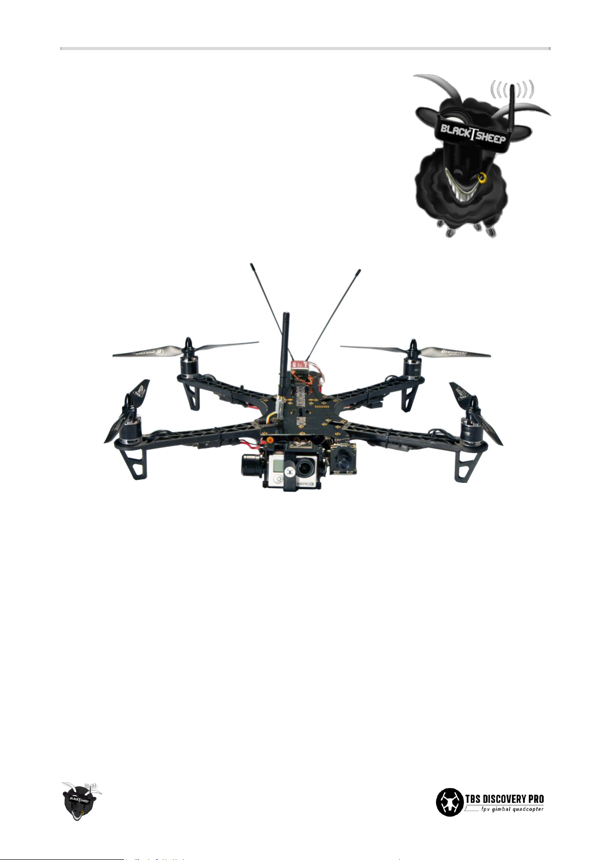
By implementing the wiring into the frame, the copter is easy to build and outperforms similar quads in
terms of FPV range and video link quality. The DJI Flamewheel arms as predetermined breaking point protect
your electronics and are easily replaceable in the field.
Features
● Integrated brushless gimbal & control board (plug & play!)
● Built-in camera switch (GoPro live-out and pilot's camera)
● Frame acts as power distribution board
● Ready for long range FPV
● TBS CORE (On Screen Display) with digital current sensor
● Lightweight anodized CNC aluminum gimbal
● Custom Gimbal IMU board
● Tried and proven frame design - based on the world's most popular FPV quad!
● Integrated brushless gimbal controller (BaseCam)
1
TBS DISCOVERY PRO Quadrotor
Durable and crash resistant multirotor perfect for
amateur and pro aerial videographers
Revision 2015-05-26
The TBS DISCOVERY PRO gimbal frame is the perfect tool for amateur and
pro aerial videographers. Sporting a fully stabilized, vibration isolated
camera gimbal it is the most powerful, compact, robust and versatile "take
anywhere" quadrocopter for filming available to date. All the wiring is
integrated into the frame, the copter is easy to build and outperforms
similar quads in terms of FPV range, flight time and video link quality.
Page 2

Before we begin
Thank you for buying a TBS product! The TBS DISCOVERY PRO is a new multirotor aircraft from Team
BlackSheep (TBS) for hobbyist, semi-pro and pro aerial videographers. It features the best design practices
available on the market to date, providing great flying stability and incredible FPV characteristics.
Please read this manual carefully before assembling and flying your new TBS DISCOVERY PRO quadrotor.
Keep this manual for future reference regarding tuning and maintenance.
Disclaimer
Our request to you; the aircraft may not be used to infringe on people's right to privacy. We have designed a
toy with mind blowing capabilities. It is your responsibility to use it reasonably and according to your
experience level. Use common sense. Fly safe. You are on your own. TBS has no liability for use of this
aircraft.
● Locate an appropriate flying location
● Obtain the assistance of an experienced pilot
● Practice safe and responsible operation
● Always be aware of the rotating blades
● Prevent moisture
● Keep away from heat or excessive amounts of sunlight
2
Page 3
Specifications
The following specifications are for the normal TBS DISCOVERY PRO. Long Range hardware will be different.
Type:
Asymmetric spider quadrotor
Airframe:
Reinforced black fiberglass (rear top RF transparent, bottom PDB)
Battery:
4S (14.8V) 3300 to 4500mAh LiPo pack, max. 31 x 47 x 157mm
Propellers:
9x5-inch or 10x5-inch (2xCW, 2xCCW)
Motor:
2216 class, ~900kV, 180-220W, 16x19mm mount pattern
Speed controllers:
18 to 30A 400Hz Multirotor ESCs
Receiver:
6 channels or more, 8 channels recommended
Flight controller:
Standard quadcopter controller with optional GPS module
Current sensor:
50A on-board
Camera gimbal:
GoPro HD Hero1/2/3 supported, 2-axis, roll and tilt stabilization
Gimbal controller:
BaseCam 12V, tied to CORE to auto-switch profiles, GB2208-80 motors
Center of Gravity:
15mm in front of Center of Thrust mark
Duration:
8 to 13min (dependent on drive train and battery system)
Distance:
up to 4km range (and return)
Altitude:
up to 1.5km / 5000ft
All-up-weight:
1500 to 2000g
Required tools
● Hex (Allen) screwdrivers (0.9mm, 1.5mm, 2.0mm, 2.5mm)
● Soldering iron (50 to 100W recommended)
● Solder (Sn
60
Pb
40
or Sn
62
Pb
36
Ag2, multicore flux)
● Propeller balancer (recommended)
There will be some soldering required to connect the speed controllers, battery lead, R/C header and CORE
voltage configuration for the video transmitter and camera. We offer most of the following items on our
website individually or as part of an
Almost-Ready-to-Fly
(ARF) kit.
The equipment and parts we offer has been truly tried-and-tested to meet our standards for an excellent
flight experience. But you can of course replace these with equal components or of similar type.
3
Page 4
Parts list
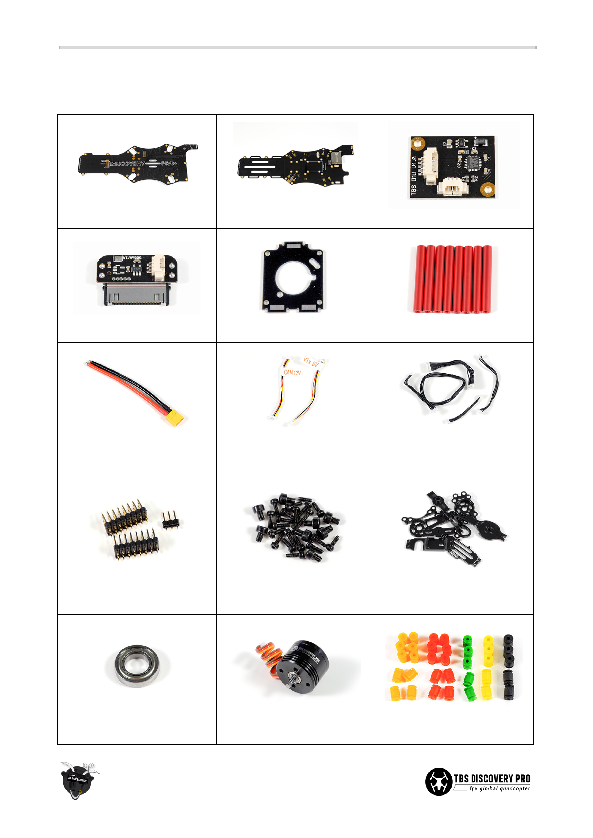
Before building your TBS DISCOVERY PRO, make sure the following items are included in your kit.
1x Top frame plate
1x Bottom frame plate
1x Gimbal IMU board
1x GoPro link card
1x Pilot camera mount plate
7x Red aluminum spacers
1x Battery pigtail 14AWG with
XT60 connector
2x VTx and camera Molex
Picoblade cables
4x Black Molex 1.25 Picoblade
cables
3x Pin headers for R/C and RSSI
connections
4x Hex screws bags (M2.5x5,
M3x6.5, M2.5x6,
M3x4+M2x6+M2x12)
10x Black anodized aluminium
gimbal parts
1x Gimbal bearing
2x Gimbal motors
25x Orange/Red/Green gimbal
dampeners
4
Page 5
Required parts
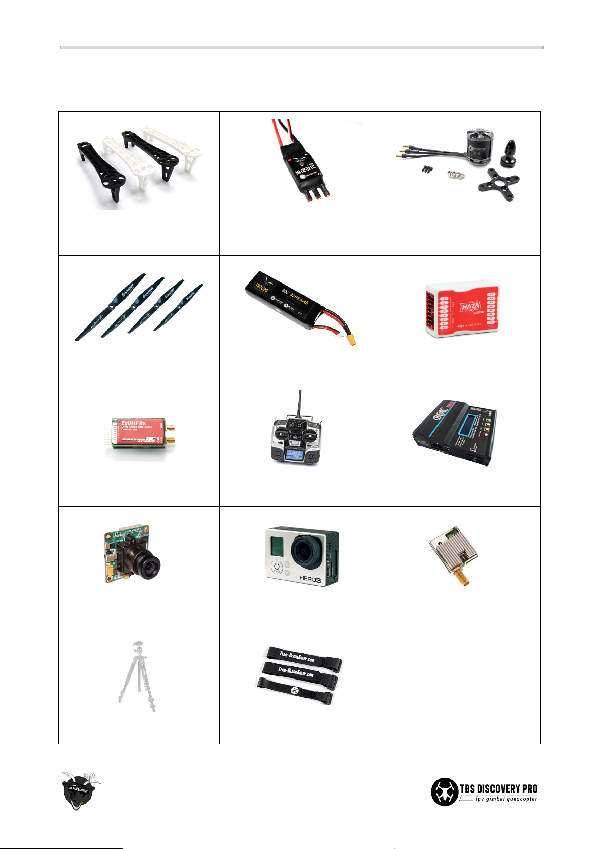
To get in the air the following equipment and parts are needed for assembly.
4x DJI Flame Wheel arms
4x 400Hz Multirotor Speed
Controller 18-30A
4x 900kV brushless motors (incl.
prop adaptor and mounting
screws)
4x 9x5 or 10x5-inch propellers
(2xCW, 2xCCW)
1x 4S 3300 to 4500mAh LiPo
battery
1x Multicopter flight controller
1x R/C receiver (6-channels or
more, 8-channels preferred)
1x R/C transmitter (6-channels or
more, 8-channels preferred)
1x LiPo battery charger
1x Pilot camera (32x32mm)
1x HD recording camera (GoPro
HD Hero 1/2/3)
1x Video transmitter
1x Equipped ground station
3x Velcro straps - now included!
Other essential parts:
1x Threadlock (purple/blue) low
strength
20x Zip-ties
2x Self-adhesive foam pads
5
Page 6

Build guide
The TBS DISCOVERY PRO comes in the usual quality finish and plug & play style the TBS DISCOVERY line is
famous for. The essentials are fully integrated on the plates, to make the final assembly as easy as humanly
possible. No separate boards, wire spaghetti, purchasing stuff from multiple sources or components that
don't match. It is all in the box, just take it out, mount the ESCs, motors and props, a flight control and you
are ready to shoot videos.
TBS CORE
The CORE has won over the FPV enthusiasts worldwide and as the easiest to use OSD module. Clean data
layout and only the most important information presented on screen. Clutter-free, permanently visible, zero
wires for installation, and nicely tucked away under a tin shield. The most robust and secure solution for on
screen telemetry.
Features:
● Accurate flight pack voltage and mAh consumption display
● Reliable power supply for FPV camera and transmitter
● Flight time shown once a minute
● Display RSSI (R/C signal strength) from all major UHF systems and some regular R/C systems
● Single battery FPV system - less chance of failure!
At the heart of the TBS DISCOVERY PRO sits a new CORE integrated into the frame. It provides a rudimentary
OSD and clean power distribution to the FPV camera (user installed), video transmitter (user installed),
gimbal electronics, IMU board and gimbal motors, regardless of input voltage (2S-10S). It delivers up to 2A at
5V and 0.65A at 12V, though the 12V rail is powered from the 5V part to support a wide input voltage range,
so make sure to leave enough headroom when picking gear. If you need more power than that you have to
power your equipment (e.g. VTx, camera, LEDs) separate from another power source (supply pads +/- on
bottom frame and/or additional voltage regulators)!
The frame includes a 50A current sensor which is connected directly to the CORE. If you are planning to fly
with UHF, we made sure to cover the CORE with a tin shield to isolate the CORE nicely from the rest of the
electronics on frame. Configuring the CORE is made easy via the readily available buttons on the top plate.
This means that CORE is neatly tucked away and protected under the tin shield, while making changes can be
done with a few button presses.
Note: If you draw more current than provided, the DC-DC board will shut down due to overheat/
overcurrent protection! This might occur when powering a powerful video transmitter. When that happens,
you will not damage your DCDC but be aware that the video link/gimbal will experience drop-outs during
this period. Test it on the ground for several minutes before you maiden your PRO with equipment other
than TBS recommended gear.
6
Page 7
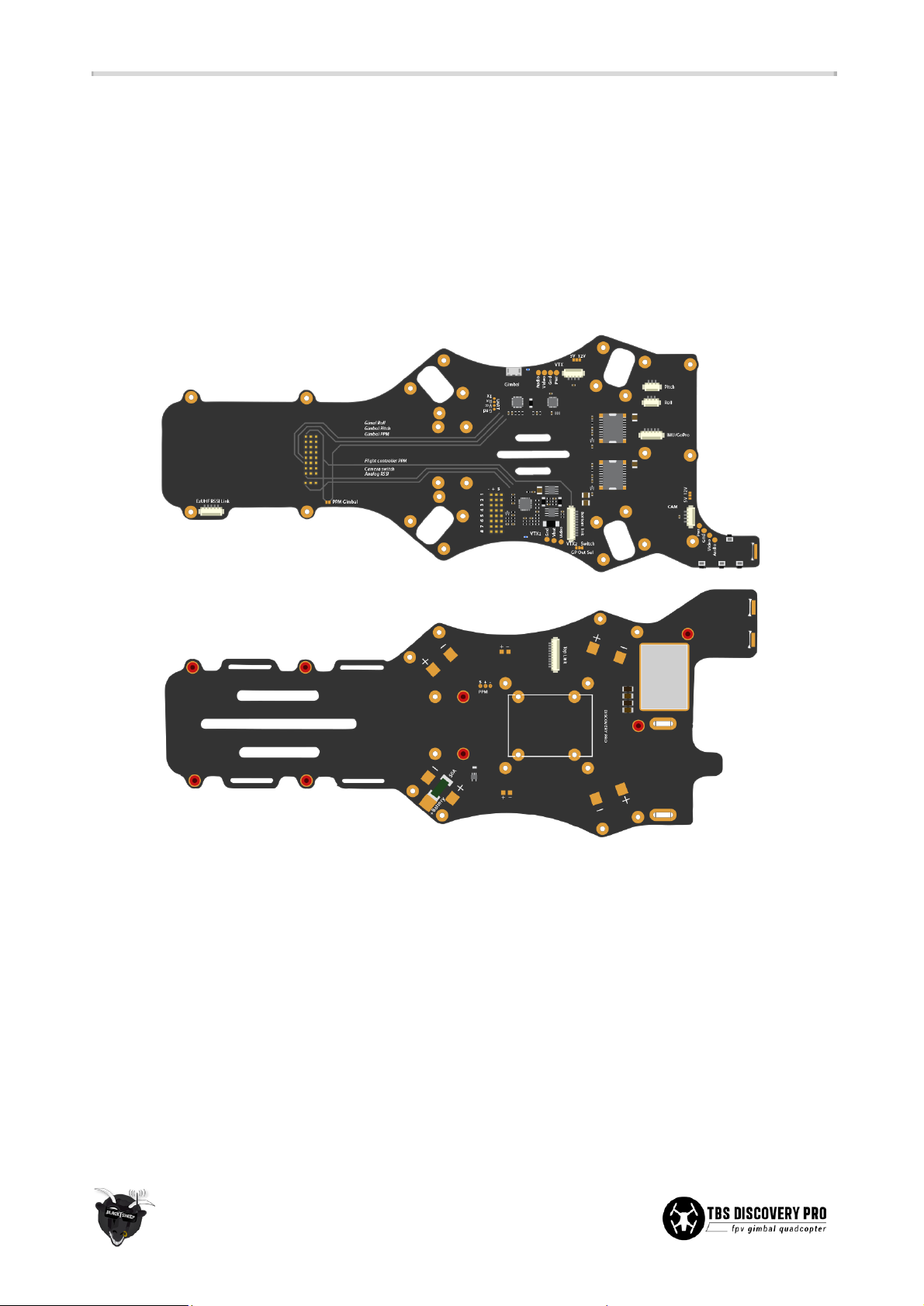
Frame layout
The TBS DISCOVER PRO frame is designed to reduce wiring and clutter. With simplicity in mind, we put all the
electronics for the CORE, brushless camera gimbal and camera switching nicely integrated onto the top and
bottom plates. All connections for the brushless gimbal motors, gimbal IMU and GoPro feed is plug&play.
Calibrating the gimbal and configuring the CORE is made easily accessible via 4 push-buttons. A plate-to-plate
bottom link connector shares the required power and signals between the plates. There are also two blue
LEDs to indicate the state of the CORE and gimbal controller. There is even a special EzUHF “OSD Link”
connector for extended R/C uplink stats on the video display.
With the advent of PPM compatible receivers and flight controllers, setting up a multirotor was made really
easy; just plug in a single cable into the flight controller. PPM essentially stacks all the channels after another
in a sequentially stream requiring only one hardware pin, while the traditional PWM channels all require its
own dedicated hardware pin.
The advantage of PPM really becomes apparent when paired up with additional controllers (e.g., gimbal.) By
sharing the same PPM output, a controller can demux only the needed channels, for instance a flight
controller can demux channel 1 to 4 for R/C control, while a gimbal controller can use channel 5 and 6 for
tilt/roll. Compared to traditional PWM, this removes 5 servo-cables from the system and really simplifies the
build process.
7
Page 8
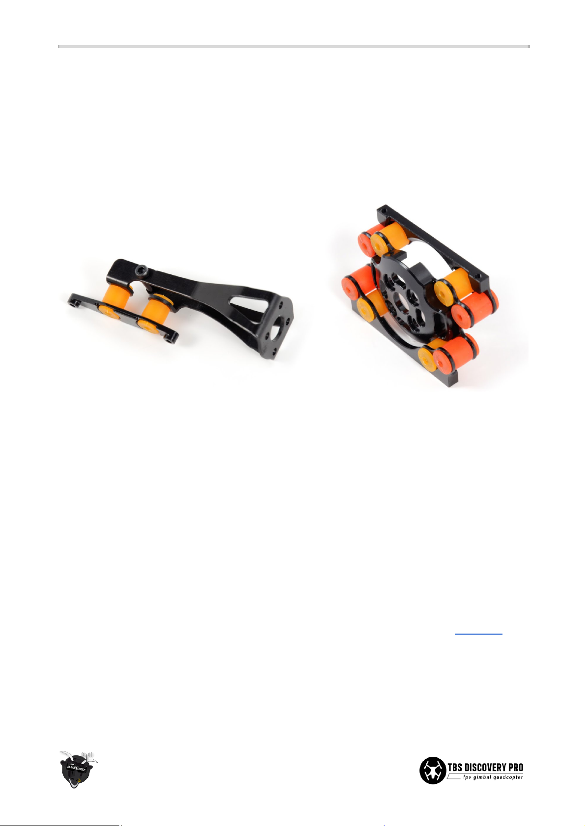
Vibration free recordings
The TBS DISCOVERY PRO is designed with a new vibration damping system where the gimbal rests on an
array of 8+2 silicone mounts to form a push-pull compression system. This eliminates vibrations from
propagating to the gimbal frame and HD camera.
We provide 5 rounds of damping balls (soft, medium, hard, harder, extra hard)) which are interchangeable
and mixable to support a wide range of setups and scenarios. A late addition to the damping system was a
lever arm on the back of the roll motor to reduce slow oscillating jolts from showing on the HD footage.
Think of the entire damping layout as accumulating hardness. The green damping balls are the softest, red
the medium and orange the hardest. Vary between the colors and layouts, keeping the left and right half of
the gimbal symmetrical to find the system that works for you. Top and bottom do not need to remain
identical.
TBS can only ensure proper operation with the TBS-approved setup: 900kV motors, 9x5 Graupner propellers,
TBS BULLETPROOF ESCs. All other layouts are subject to optimization. Use the provided damping balls to
experiment to find an optimal combination. With a bit it testing, you will be able to get the “jello”-effect out of
any setup.
The drivetrain should be balanced and tracking before trying to reconfigure the damping balls. The primary
culprit for vibrations are unbalanced propellers, followed closely by unbalanced motors/shafts and bad
bearings. Fortunately, balancing them is a relatively easy task. TBS is offering a Prop Balancer for this purpose
and more details on how to perform the procedure, please see our support forum section at fpvlab.com.
8
Page 9

Long range photography
Team BlackSheep are the undisputed kings of long range FPV. With the TBS DISCOVERY PRO you can make
camera shots that rival those of real helicopters. You can chase BMX drivers down an entire slope. You can
film boats and yachts from the shore. You can shoot breathtaking action scenes from the director's seat!
Since you're piloting from the camera view, your skill is the limit.
We offer 2 basic setups, each with their different flavors of ranges. The TBS 5.8GHz FPV system gives you
ranges between 500m (25mW) to 3km (600mW). Please make sure your 2.4GHz R/C can match this distance!
To fly further, we offer the EzUHF Tx & Rx long range control system and the Lawmate 2.4GHz long range
video system. Compatible with all remote controls! With the 11dBi Yagi ranges of 10km or more are easily
achieved. The battery life now is your limit.
Frequency choice
Frequency choice depends on the ranges you want to fly. Using 5.8GHz video is an ideal frequency if you do
not plan on flying far away from yourself or behind objects. It is compatible with 2.4GHz remote controls.
Using 2.4GHz video (TBS video frequency of choice) will give you nearly unlimited range and far superior link
quality, but you can not use your 2.4GHz remote control on the same quad because of limited separation (it
is no problem for our R/C buddies to fly with 2.4GHz remote controls next to you though!). You will need an
EzUHF or any other UHF control system available on the market.
1.2GHz works very well in urban environments where the 2.4GHz band is completely polluted.
By using the same connector type across all transmission frequencies, the TBS eco-system allows quick and
effortless switching between the frequencies.
Typical ranges (based on customer feedback) with omnidirectional antennas:
● Lawmate 2.4GHz 500mW - 4km
● TBS 5.8GHz 25mW - 400m
● TBS 5.8GHz 200mW - 1.4km
● Boscam/Foxtech/HobbyKing 5.8GHz 500mW - do NOT buy, bad design!
● Boscam/Foxtech/HobbyKing 5.8GHz 400mW - 2.5km
● ImmersionRC 5.8GHz 600mW - 2.5km
More range can be achieved by using higher gain (directional) antennas. With the 11dBi TBS Yagi on 500mW
Lawmate 2.4GHz gear, 10km of range is no problem at all. The battery normally only lasts for 8km of flight
(4km and return.)
9
Page 10
Video switching
Another great feature of the TBS DISCOVERY PRO is the ability to switch the video feed between the live FPV
pilot camera and the gimbal camera. Fly through the FPV camera to line yourself up for a shot and then
switch to the GoPro footage to position the camera (2-axis). Depending on if it is a close flying area or wide
open field, switch back to the FPV feed to maneuver the quadcopter. Pay attention when flying through the
GoPro feed because the gimbal will make it hard to judge the quad’s attitude and flying direction.
Switching the video feed is done through a dedicated R/C channel on the receiver. Similarly, one or two slider
switches on your R/C transmitter allows control over the 2-axis gimbal. Connect a servo-cable from the R/C
receiver to the designated connectors on the top plate of the frame.
Electronics installation
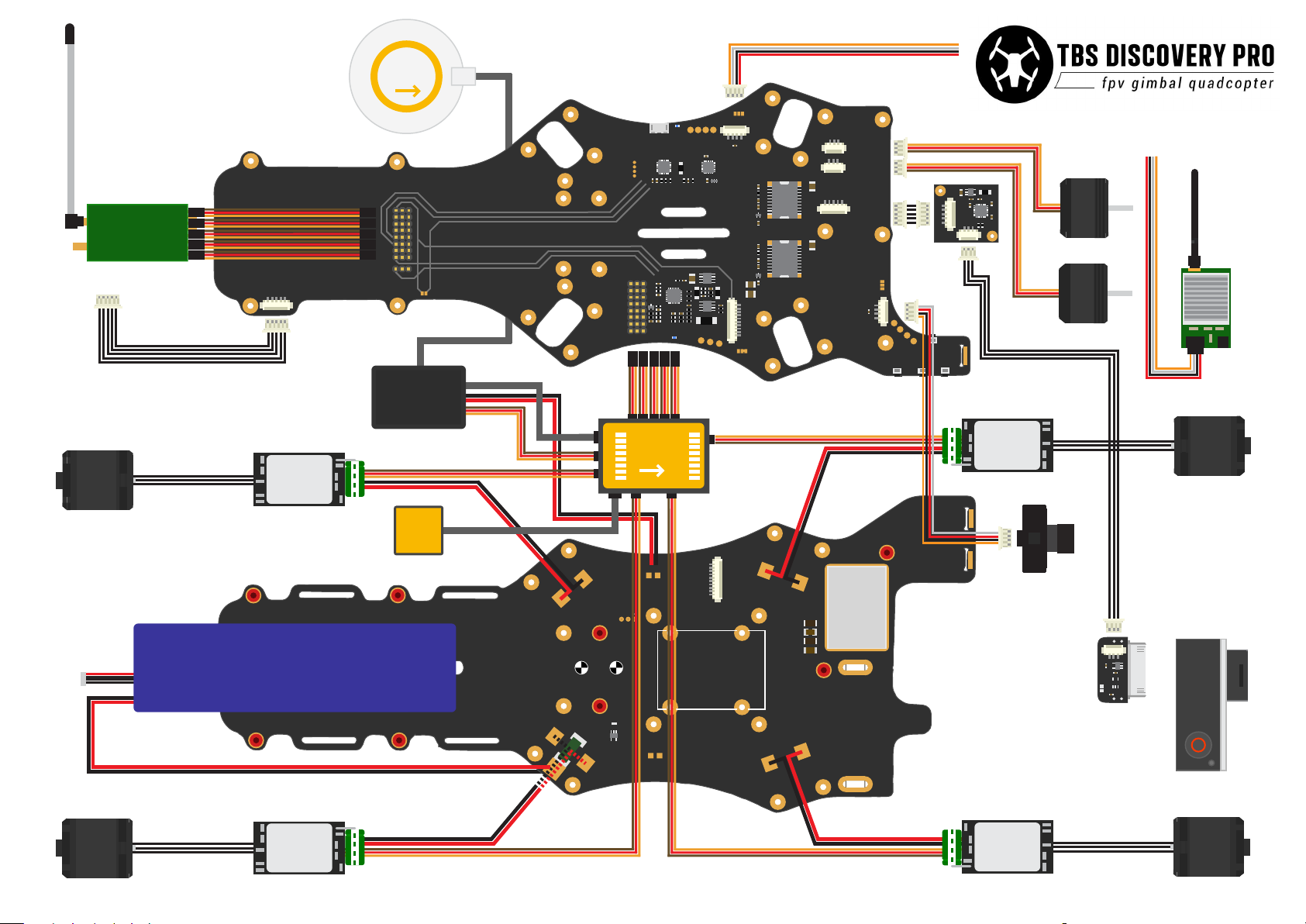
The electronics installation is split into two sections; one for the R/C equipment and the second for the FPV
gear. We recommend finishing and dry-testing the R/C system before moving on to the FPV section to
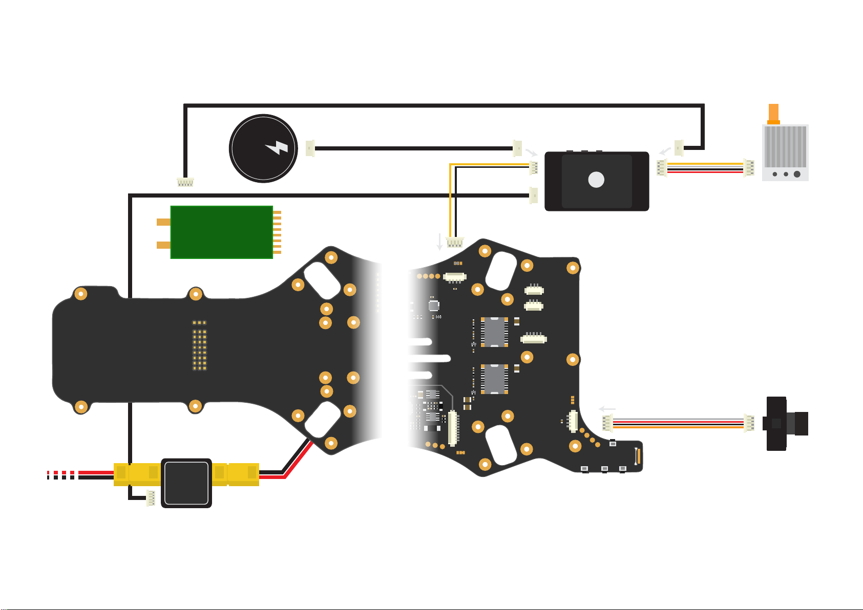
simplify troubleshooting. A detailed overview diagram of the electronics installation is available as an
appendix to this document.
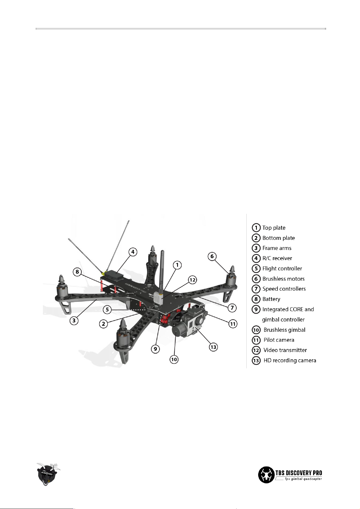
Before adding the equipment to the frame it is a good idea to become familiar with the recommended
positioning of the equipment, as shown in the image above.
10
Page 11
GPS
RC receiver
CH1
CH2
CH3
CH4
CH5
CH6
CH7
CH8
(For channel setup, refer to
the manufacurer’s manual)
(EzUHF only)
Motor - CCW
Baery
Top frame
EzUHF RSSI Link
BEC regulator
Speed controller
Bottom frame
LED unit
PMU
LED
(Oponal)
PPM Gimbal
Gimal Roll
Gimbal Pitch
Gimbal PPM
Flight controller PPM
Camera switch
Analog RSSI
A/E/T/R/U
EXP
X3
M3
LED
--
X2 or
Gimbal
Tx
UART
Rx
Vcc
Gnd
- + S
8 7 6 5 4 3 2 1
NAZA
+
--
5V 12V
VTX
Pwr
Gnd
Video
Audio
Bottom link
VTX2
Gnd
Vbat
Video
VTX2 Switch
GP Out Sel
Flight controller
(For flight controller setup, refer
to the manufacurer’s manual)
M2
M1M4
+
Top Link
Pitch
Roll
IMU/GoPro
TBS IMU
IMU
5V 12V
CAM
Pwr
Gnd
Video
Audio
Speed controller
FPV camera
--
Electronics installation
rev. 10.2013 - by ivc.no/tbs
Pitch motor
Roll motor
Motor - CW
Generic video
transmier
+
S + -
PPM
DISCOVERY PRO
GoPro link
GoPro camera
500mA/1A
Motor - CW
Speed controller
CoT CoG
--
50A
+
--
+
+Bat ter y
ESCs with 5V BEC, disconnect all RED wires except one
+
--
Speed controller
Motor - CCW
Page 12
Choosing the right setup
If you are just getting into the hobby and you have absolutely nothing, consider the following components to
buy. Use these suggested setups as a “shopping list” if you are just getting started. Any existing gear you
already own (e.g. remote controls, chargers, batteries) can be used with the TBS DISCOVERY PRO.
These setups, with the exception of the Camera Tripod and the Remote Control, are available from Team
BlackSheep. Remote controls can be purchased at your local hobby shop, camera tripods are available from
big electronics wholesalers or Ebay.
TBS DISCOVERY PRO setup for short range flights
● Expected flight time: 10-12 min
● Approximate cost: US$ 2’350 - US$ 2’750
● Experience level: Beginner to Expert
● Ideal for: Parks, R/C clubs, front lawns
R/C transmitter/receiver:
Graupner MX-12 2.4GHz radio with bundled receiver (GR-6)
or Futaba 8FG / 7C 2.4GHz radio with included receiver (R6208SB /
R617FS)
Quadrotor equipment:
4x DJI Flame Wheel F450 arms
4x TBS BULLETPROOF 30A 5V SBEC speed controllers
4x TBS 900kV2 brushless motors
4x Graupner E-Prop 9x5-inch propellers
1x DJI NAZA-M flight controller (optional GPS add-on)
Battery:
TBS 4S (14.8V) 3300mAh - 4500mAh 35C Lipo pack
Battery charger:
Graupner Ultramat 14S (premium) or TBS B6AC 80W (budget)
FPV transmitter:
TBS ROOKIE BOSCAM 5.8GHz 200mW video transmitter
FPV receiver:
TBS RC508 5.8GHz video receiver or Dominator 5.8GHz module
FPV pilot camera:
TBS 59 or TBS 69 FPV camera
FPV goggles:
FatShark Dominator video glasses
HD camera:
GoPro HD Hero 3 Black edition
Ground station accessories:
TBS 3S 5000mAh Ground Station Lipo
Camera Tripod to mount your gear (e.g. Cullmann Primax 150)
11
Page 13
TBS DISCOVERY PRO setup for long range flights
● Expected flight time: 10-12 min
● Cost range: US$ 2’500 - US$ 3’000
● Experience level: Expert
● Ideal for: Long, wide open fields, plains, coastlines and valleys or urban flying
R/C transmitter/receiver:
Futaba 8FG / 7C or Graupner MX-12 radio
+ EzUHF 433MHz transmitter module and SRH-771 UHF antenna
+ EzUHF Lite 8-channel 433MHz receiver
Quadrotor electronics:
4x TBS BULLETPROOF 30A 5V SBEC speed controllers
4x TBS 900kV2 brushless motors
4x Graupner E-Prop 9x5-inch propellers
1x DJI NAZA-M flight controller (optional GPS add-on)
Battery:
TBS 4S (14.8V) 3300mAh - 4500mAh 35C Lipo pack
Battery charger:
Graupner Ultramat 14S (premium) or TBS B6AC 80W (budget)
FPV transmitter:
Lawmate 2.4GHz 500mW Video Tx (stock or tuned)
FPV receiver:
Lawmate 2.4GHz Video Rx (stock or tuned) with 11dBi Yagi
FPV pilot camera:
TBS 59 or TBS 69 FPV camera
FPV goggles:
FatShark Dominator video glasses
HD camera:
GoPro HD Hero 3 Black edition
Ground station accessories:
TBS 3S 5000mAh Ground Station Lipo
Camera Tripod to mount your gear (e.g. Cullmann Primax 150)
12
Page 14
Camera gimbal assembly
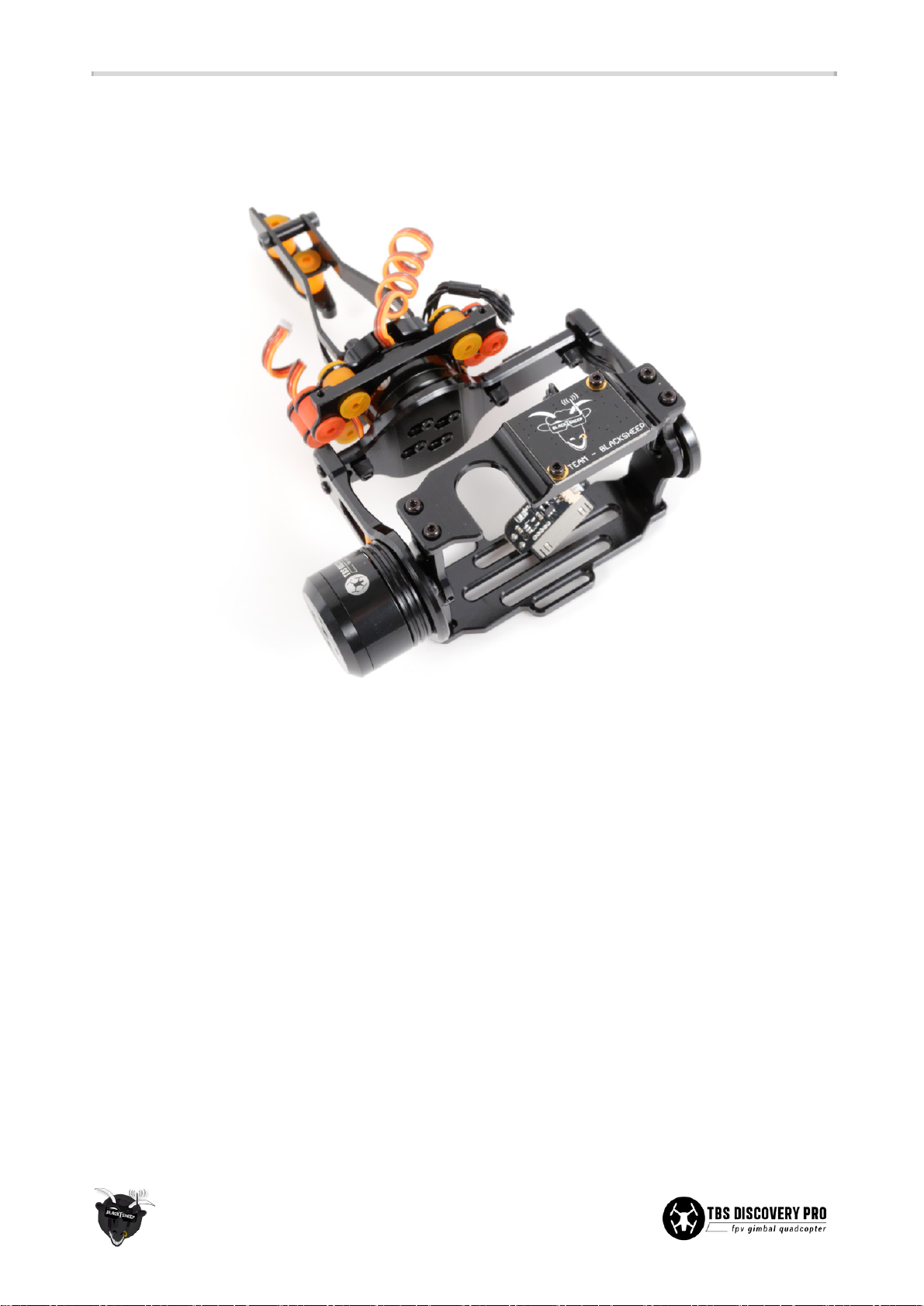
Start by assembling the brushless gimbal. There are a few steps which requires extra attention to detail in
order to get the desired silky smooth operation of the gimbal. These are outlined in the following sections.
Vibration damping system
Start by inserting the damping balls on the mounting plate and frame brackets. This makes it easier to install
the main mounting plate later on.
● The kit includes 35 damping balls of varying elasticity. Play around with different combinations to
find an optimal match which opposes/absorbs the vibrations from the frame. In general it is
recommended to go as hard as possible up to the stage where vibrations/“jello” begin to propagate.
● The harder you go on the front mounting brackets, the softer you can go on the back lever plate.
● A list of suggested combinations are available below.
○ Green - soft silicone (5)
○ Red - medium silicone (10)
○ Orange - hard silicone (10)
○ Yellow - harder silicone (5)
○ Black - extra hard silicone (5)
13
Page 15
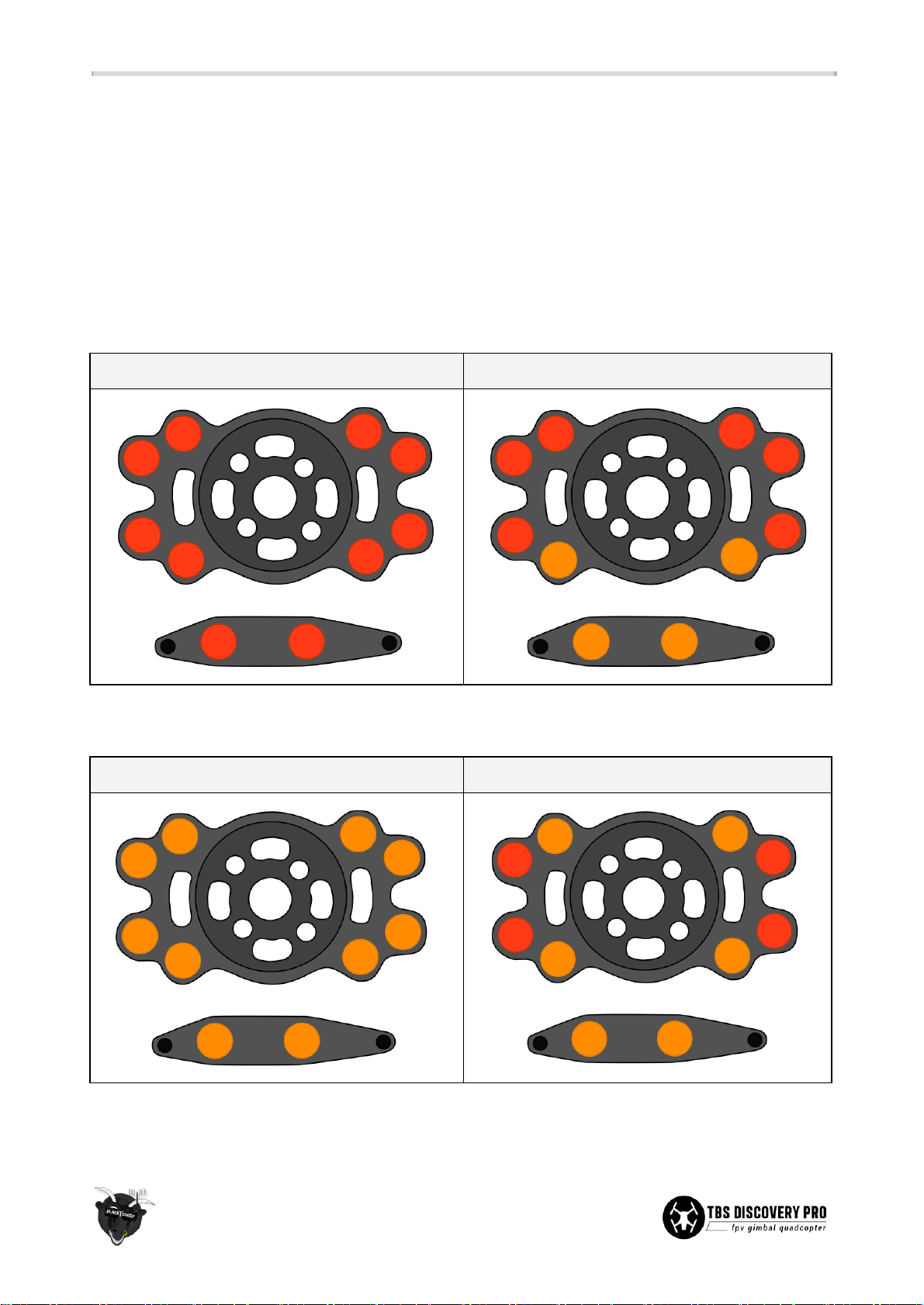
● On the main mounting plate, the cable for the motor will exit on the top notch and the plate needs to
be oriented accordingly. Four of the top damping balls will face forward (toward the gimbal) holding
the mounting bracket to the top frame, while the bottom four damping balls will point the opposite
direction (backward) and hold the bottom end of the mounting bracket. This creates the ideal
push-pull compression state where the gimbal rests nicely on the damping balls and allows them to
operate under ideal conditions.
● Start out by using the recommended damping layouts shown below and experiment.
GoPro HD Hero1 and GoPro HD Hero2
Alternative #1
Alternative #2
GoPro HD Hero3 and GoPro HD Hero3+
Alternative #1
Alternative #2
14
Page 16
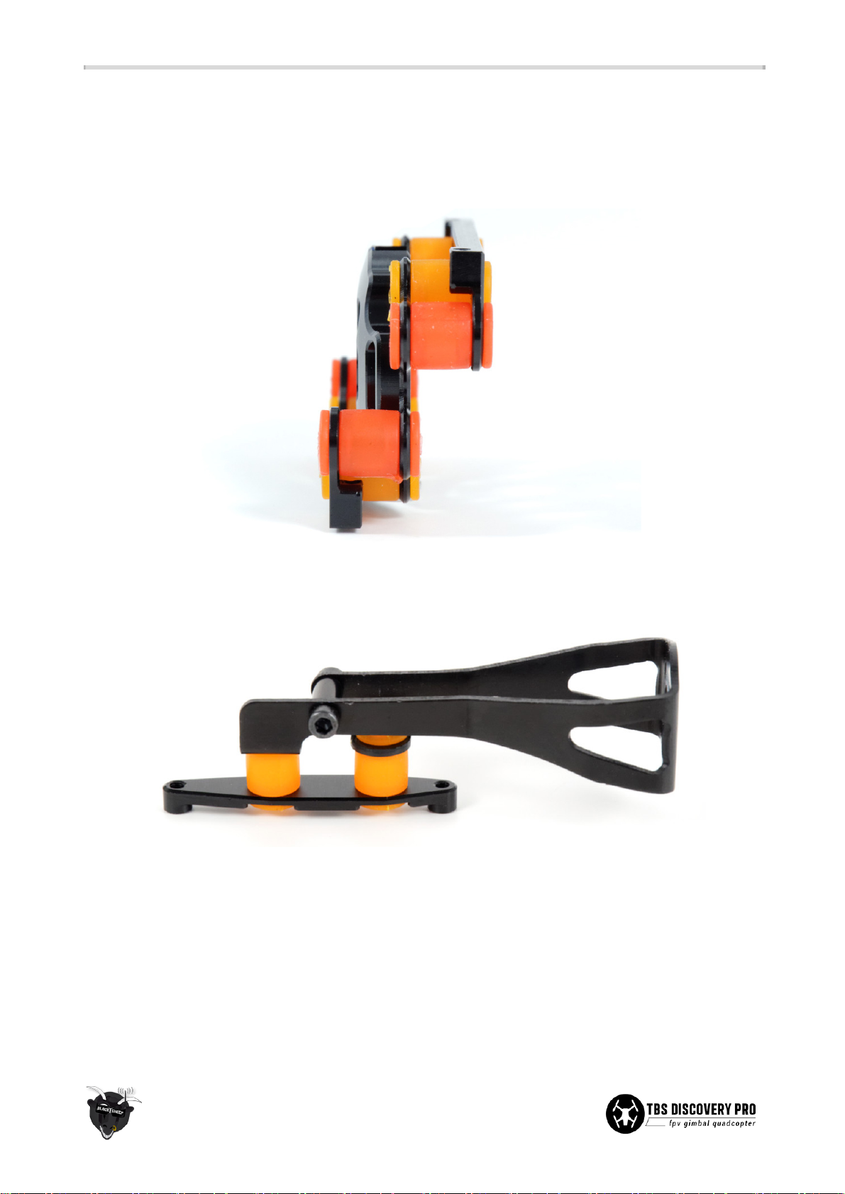
● Use a short length of a servo-wire or a piece of string to more easily feed the damping balls through
the 16 holes on the base mounting plate and frame mounting brackets. Wrap the wire or string
inside the groove of the balls, one or two turns, feed both ends into the hole, and pull through using
a plier.
● The same applies for the lever arm, only this time it is best to start with lever then work on the plate.
15
Page 17
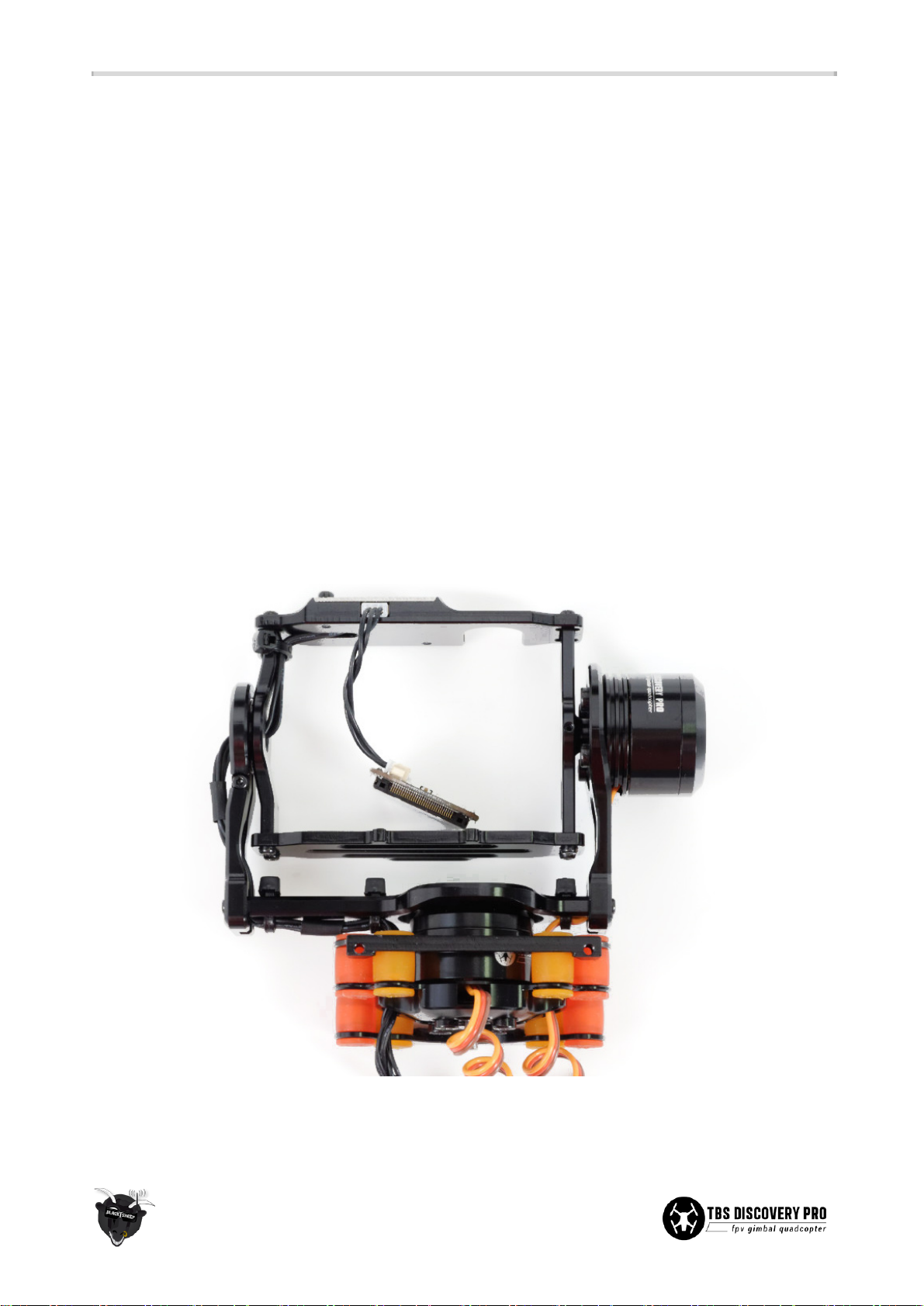
Gimbal assembly
The gimbal screws use 1.5mm (M2), 2.0mm (M2.5) and 2.5mm (M3) hex screwdrivers. Keep the screws loose
at the start and fully tighten them at the end of the assembly, this makes it easier to align all the parts. For a
good secure fit, use a very small amount of light/medium strength threadlock on all metal-to-metal-screws.
● Begin by putting on the gimbal motors on the gimbal arm and black plate. For the tilt/right motor,
make sure to align the motor cable so it protrudes hidden behind the inner side of the mount. Mount
it with 4x M3x4mm hex screws. For the roll/rear motor, orient the motor so that shaft/cable is
pointing away from the back mounting plate. Here, use 4x M2.5x6mm screws. Take note of the four
adjustable mounting holes on the roll/rear motor, use these to balance the GoPro at the end of the
build.
● Connect the 5-pin Molex connector to the TBS IMU (Inertial Measurement Unit) board and feed the
cable through the hole on the top gimbal cage plate. Align it with the two holes and use 2x
M2.5x6mm screws to secure it.
● Attach the left side cage wall, bottom cage floor, and right side cage wall to the top cage plate using
8x M2.5x6mm screws. The axis shaft flange on both walls should face outwards and the notches for
the cable zip-tie should be positioned up. This completes the central gimbal cage assembly.
● Next, put the bearing into the housing the left gimbal arm and use the long M2x12mm screw to
compress the gap until the bearing stays in place - do not overtighten, just clamp the bearing.
16
Page 18
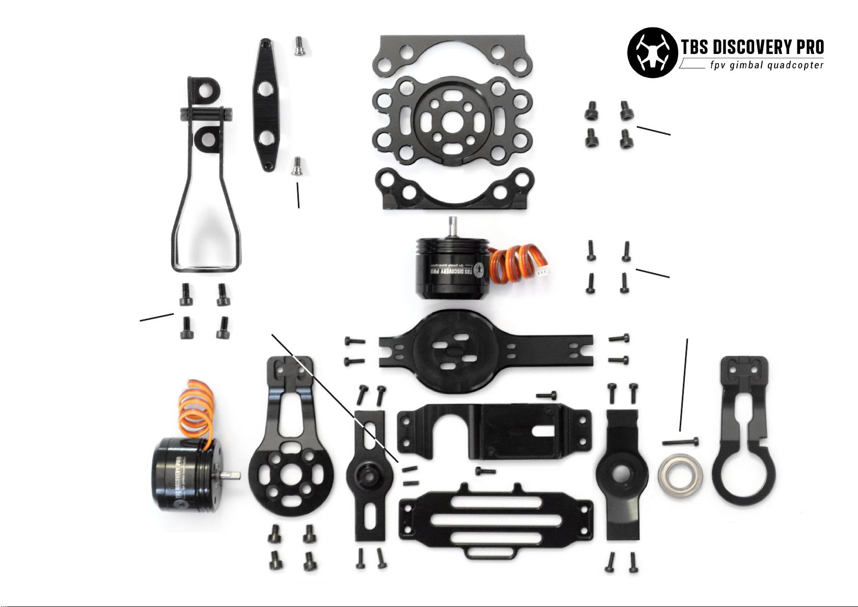
Note: Parts with the same number
belong to the same group.
(4)
Gimbal assembly diagram
rev. 01. 2014 - by ivc.no/tbs
(1) M3x4mm motor mount screws
(4) M2.5x5mm frame
screws
(2) M2.5x6mm gimbal screws
(5) M3x6mm lever-to-motor
mount screws
(4) M2x6mm grub screws
(2)
(2)
(1)
(2)
(3) M2x12mm bearing clamp screw
(2)
(2)
(2)
(2)
(2)
Page 19
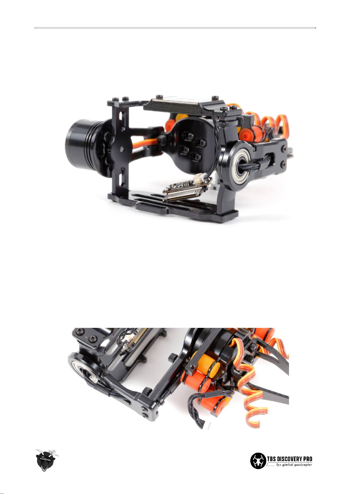
● To minimize cable tension and friction, feed the 5-pin Molex connector through the bearing and slide
the bearing over the flange on the left side of the gimbal cage (completed previously).
● Align the shrink tube pieces in such a fashion that there is no shrink tube on the inside corner of the
cage or in the bearing channel. Feed the remainder of the 5-pin cable length through the hole on the
left gimbal arm.
● Align and attach the roll/rear motor mounting plate to the left gimbal arm. Pass the 5-pin cable
through the inner “U”-gap. Do the same for the right gimbal arm.
● Use the small 2x M2x6mm grub screws to secure the tilt/right motor shaft to the gimbal cage. This
requires a 0.9mm hex (Allen) key. Align the two notches on the motor shaft with the grub screw
holes. Ensure that both screws are properly tightened, but do not overtighten as the screws could
strip.
● Strap down the cables using 4 zip-ties, use the designated holes around the inner bends of the
gimbal arms and cage. The zip-tie on the cage for the IMU cable needs to be positioned with the
zip-tie head facing backwards to avoid binding/hitting the left gimbal arm.
17
Page 20
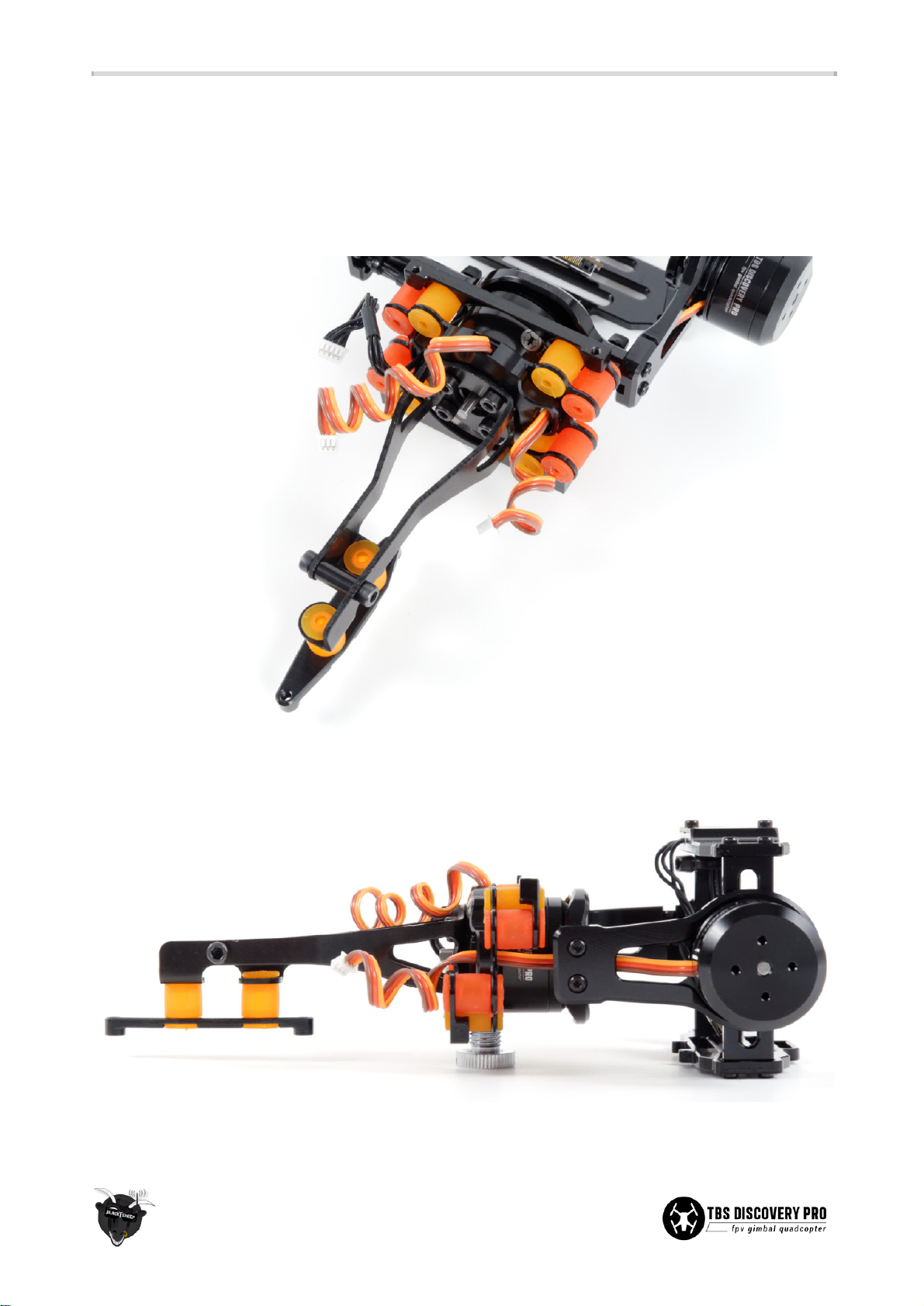
● Continue by attaching the main damping mounting plate (completed previously) and back lever arm
to the rear/roll motor. Align the cable with the notch in the mounting plate and secure it using 4x
M3x6mm screws. Feed the remaining cables through the two oval holes on either side of the plate.
Make sure the cables does not obstruct free movement or is under tension. Also check that the cage
can move freely and there is no binding (rubbing) on either side.
● Mount lever arm with the flat surface with the holes pointing down. The lever plate should have the
protruding thread holes also pointing down. This completes the gimbal arm and cage assembly!
18
Page 21
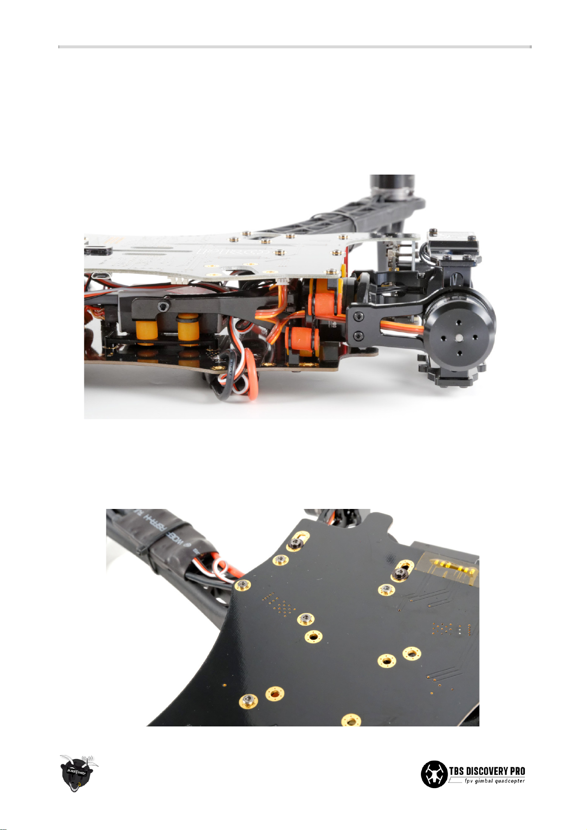
Post frame assembly
● Continue assembling the rest of the DISCOVERY PRO frame and at the end of the build, slide in the
gimbal assembly, plug in the 3 cables for pitch, roll and IMU to the designated location and secure
the gimbal using 6x M2.5x5mm frame (arm) screws. Double check that the right/tilt motor is
connected to the “PITCH” connector and the back/roll motor to “ROLL”. The cables should move
freely.
● Adjust the gimbal so that it is parallel and true to the frame. The arms and motors should
not
be
tilting at an angle, looking from the side. Use the sliding position holes on the bottom plate to make
the final adjustment.
● If the mounting brackets are slipping, add a washer to the screws to keep them in place.
19
Page 22
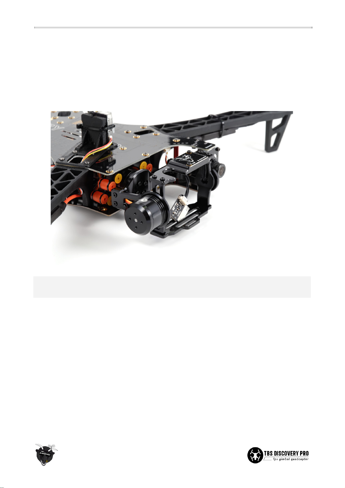
● If the lever arm touches the flight controller when installed, either move the controller slightly or
remove the spacer and two screws (these are not absolutely necessary).
● Finally, feed the GoPro gimbal velcro strap through the slots on the bottom cage mounting plate.
Properly strapped down the GoPro before flying to reduce vibrations/jello on the footage. Adjust the
balance on both the tilt and roll axis by moving the GoPro back/forth and adjusting the mounting
screws on the motor behind the GoPro, respectively. With no power applied, the gimbal should stay
perfectly still and not lean in either particular direction.
Important: Avoid rotating the gimbal multiple full turns on the tilt-axis. This puts tension on the IMU cable
which in turn introduces counter-forces and interferes with the normal operation of the gimbal.
20
Page 23
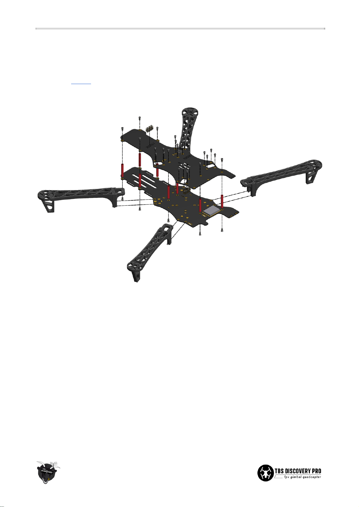
Frame assembly
The following sections will show you the essential steps to assembling the base of the frame and connect the
electronics to the frame. In addition to the following assembly instructions, we have produced a both a
summarized “How To” video and a full length “How to” build video showing the assembly and electronics
installation. A full resolution image of the frame assembly is available as an appendix to this manual.
Bottom plate
Power distribution
● Start by pre-tinning (add solder to) the battery pads, speed controller pads, auxiliary power pads (for
flight controller power), speed controller power leads and the battery pigtail. If needed, desolder and
change the XT60 connector to your preferred connector of choice (e.g. Deans, EC5.)
● Cut the the battery pigtail to 14cm and pre-tin the ends. Solder the wires to the positive (red) and
negative (black) pads located on the back-right side on the frame.
● Pick one of the available auxiliary power pads (smaller squares) and solder the flight controller power
unit and/or voltage regulator(s) to the frame. We recommend the pads on the middle-left side.
21
Page 24
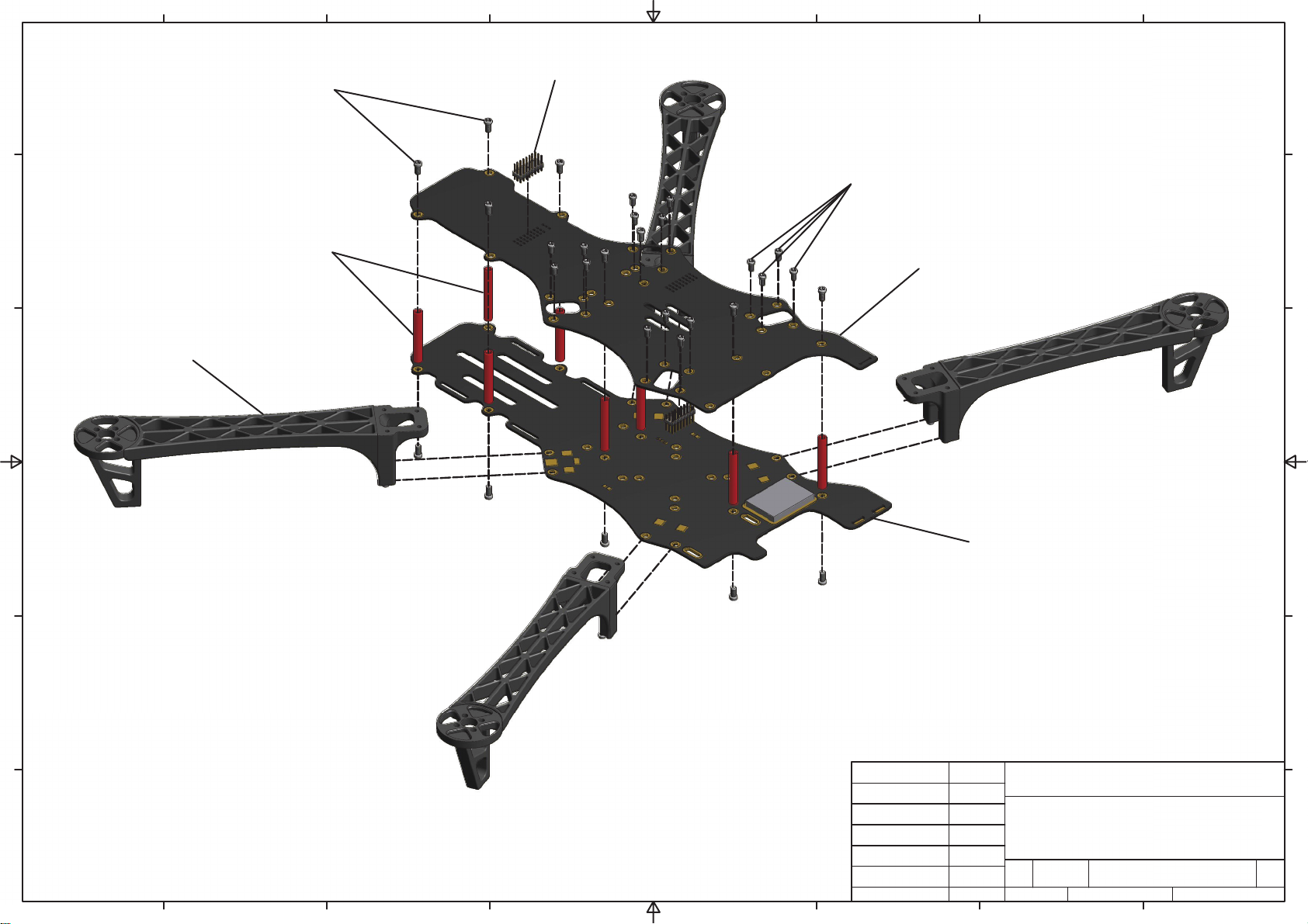
8
7
6
5
4
3
2
1
F F
(1) M3x6.5mm spacer screws
(3) Pin header
(1)
(2) M2.5x5mm frame arm and gimbal screws
(1)
E E
(7) Aluminium spacers
(2)
(2)
(1)
(6)
(4) Top plate
(1)
(1)
(6)
(2)
(6) Frame arm
D D
(1)
(3)
(1)
C C
(1)
(5) Bottom plate
(1)
(1)
(6)
B B
DRAWN
Parts with the same number
belong to the same type.
A A
8
7
6
5
4
TBS Associates Inc 31.07.2013
CHECKED
QA
MFG
APPROVED
3
TITLE
SIZE
A2
SCALE
DWG NO
tbs_disc_pro_frame_assy
2
SHEET
1 OF 1
REV
1
Page 25
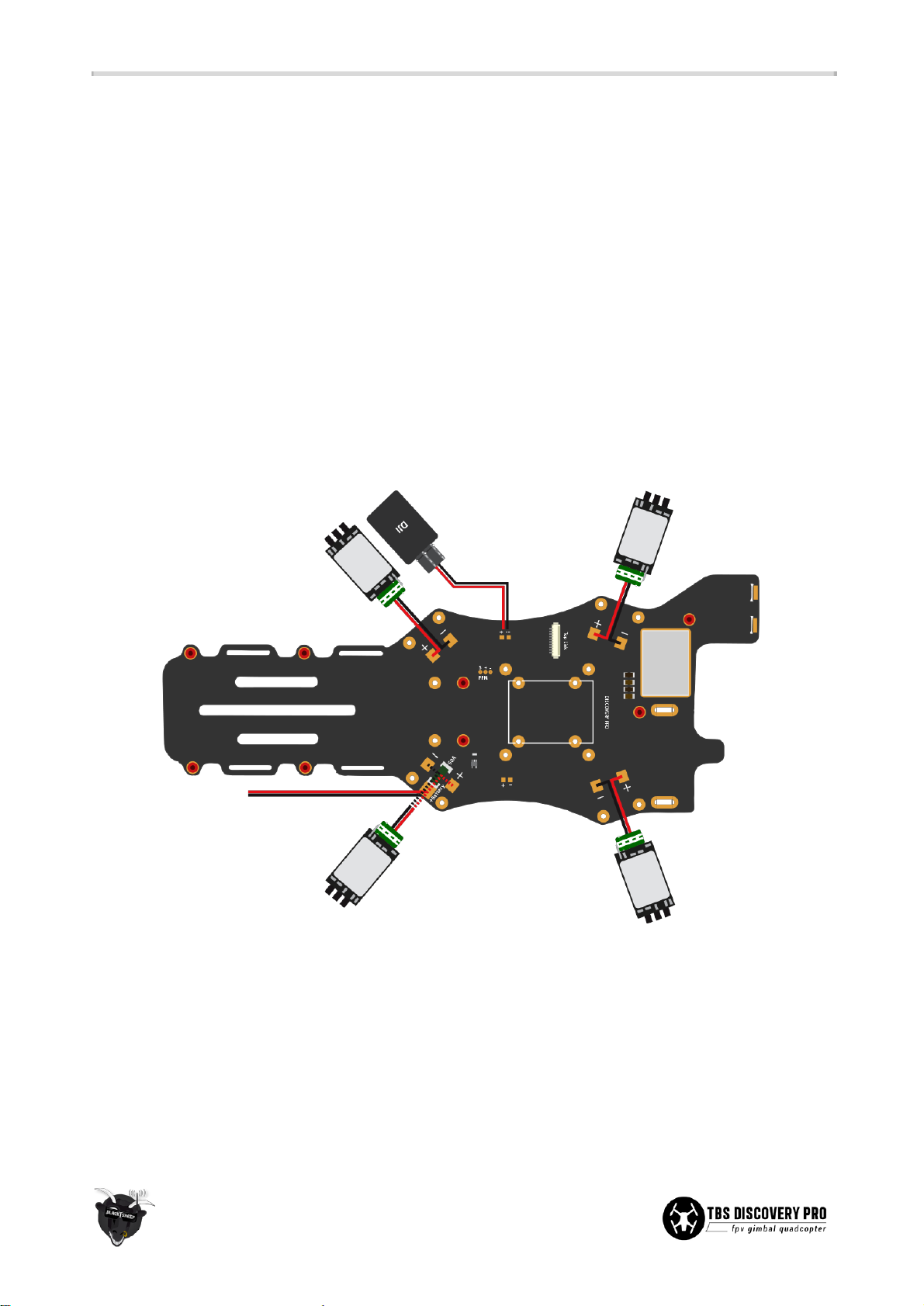
Spacers
● Next, add the red spacers (posts) to the bottom frame plate using the supplied M3x6.5mm hex
screws. Add a small drop of threadlock to help secure the frame. It is recommended to only apply on
the bottom screws for easy repairs/maintenance.
● There are three spacer positions in the battery compartment to make it easy to balance (CG) the
frame. The rear spacer position is great for 4S 3300-3700mAh packs, while the most forward position
is great for larger 4S 4000-4500mAh packs (shown in the image below.)
Speed controllers
● Position the ESC with the label facing up. Solder the positive and negative leads on the speed
controllers to the corresponding square pads on the bottom frame. The pads are located next to the
two frame arm screw holes. Heat the solder pad, hold the cable in a slight angle (so both cables will
form a “V”), remove the solder iron and keep still until the solder has had time to cool down and
settle nicely.
● Calibrate the throttle range for each ESC individually (except for DJI and TBS BULLETPROOF ESCs) by
connecting the ESC directly to the throttle channel on the receiver and setting the throttle stick high
(Wide Open Throttle - WOT) on power-on and then low until a confirmation beep is heard (motors
attached). The ESC has to be connected directly to the R/C receiver for this procedure to work. TBS is
offering a handy calibration cable for this purpose. If you are using EzUHF, set WOT as failsafe to
avoid start-up timing issues. After calibration, re-program your correct failsafe throttle position.
22
Page 26
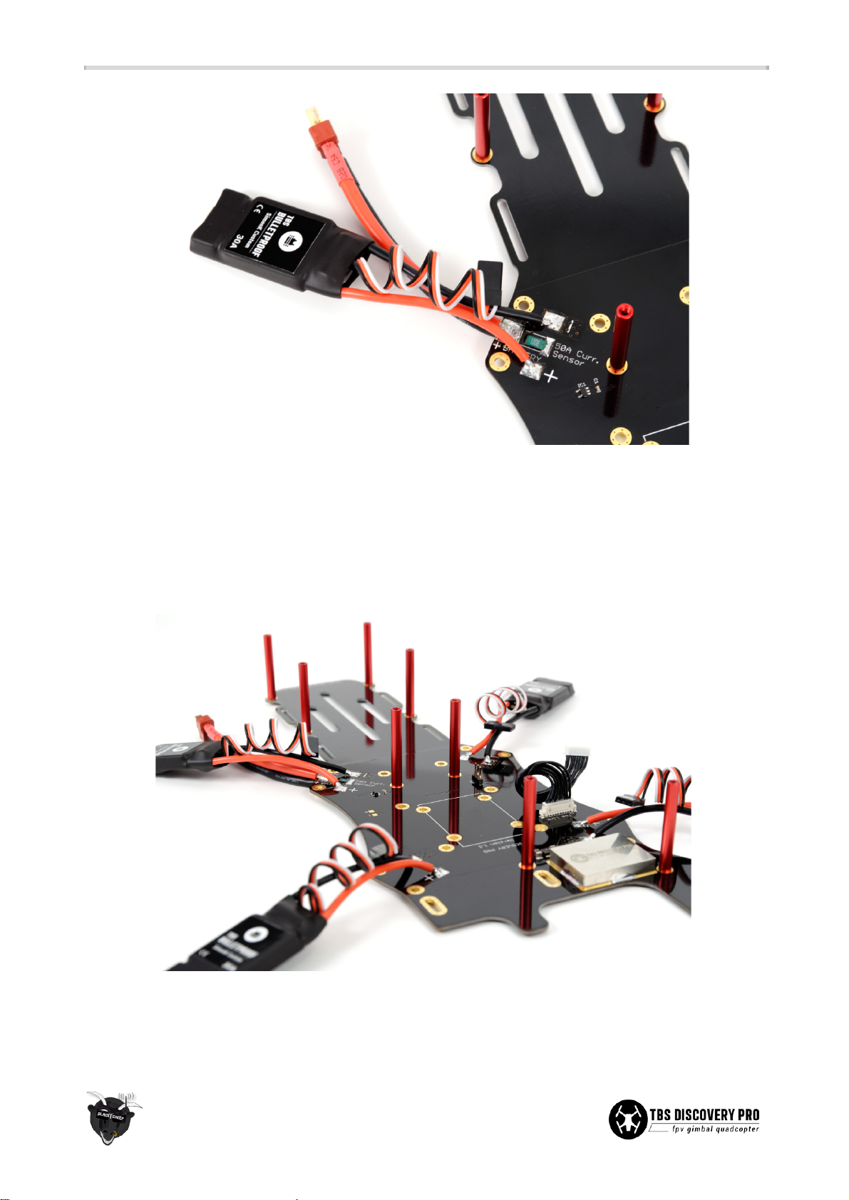
● One important note for ESCs that do not carry the “OPTO” label or are not TBS BULLETPROOF
designs, is that only one of the four ESCs should provide 5V BEC power to the flight controller. The
middle red wire on the end connector should be disconnected on three of the ESCs. If the flight
controller is providing power (e.g. NAZA-M PMU/V-SEN-unit), all ESC BECs should be disconnected.
The reason for this is to avoid voltage oscillations caused by erroneous voltage-regulator feedback.
23
Page 27
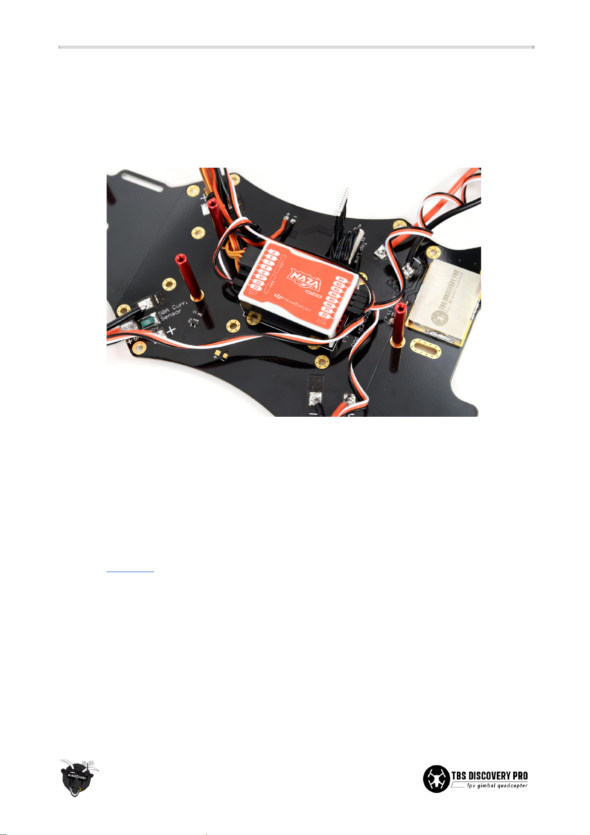
Flight controller
● Decide whether you want to use traditional PWM or PPM/S.BUS control signal mode. The frame is
laid out to work with both types of setups. As of writing, TBS suggests the DJI NAZA-M flight controller
in PPM/S.BUS mode (together with a compatible receiver) and an optional GPS add-on (for
return-to-home capability) for a clean wiring layout and great out-of-the-box experience.
● Plug in all the R/C and ESC servo-cables to the flight controller according to the flight controller
instructions. Mount the unit on the bottom plate in the centre of the white rectangle. Use a
self-adhesive foam pad (normally included) to mount the controller. Be sure to double check the
orientation of the flight controller for proper operation.
● When using PPM/S.BUS, there is a handy easy-to-reach PPM header output located on the bottom
frame. Also be sure the radio and receiver is properly mapping the channels in the PPM stream.
● For setup and tuning parameters of the flight controller, refer to the manufacturer manual or guides
on fpvlab.com. See the table below for initial TBS recommended NAZA-M gains.
● (DJI NAZA only) Open NAZA Assistant and disable the “Voltage Monitor Protection”. This prevents the
DISCOVERY PRO from prematurely descending on low battery. Use the CORE OSD to watch the
battery condition instead. Never let the voltage go past 3.5V x cell count (i.e. 3S 10.5V, 4S 14.0V) or
deplete the battery past 20% (e.g. max. 3600mA discharged on a 4500mAh battery pack.)
24
Page 28
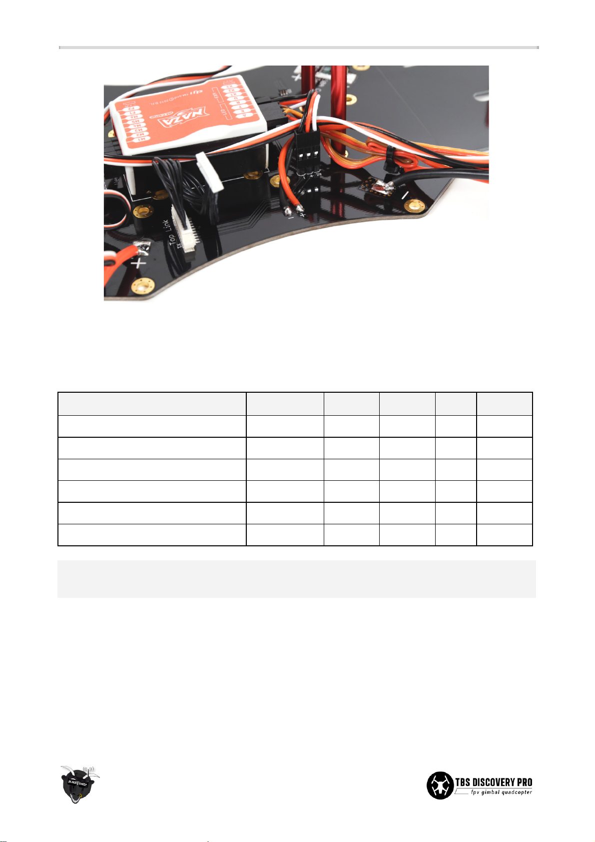
● (DJI NAZA only) To save weight and space, the PMU (V2) can be disconnected and removed after the
final configuration has been made. Although, 5V power still has to be provided from at least one of
the ESCs.
Start out using the following suggested gains for NAZA-M Autopilot and
tune accordingly
.
Setup
Gain
Pitch
Roll
Yaw
Vertical
TBS 900kV2 9x5 4S4500mAh 30A
Basic/manual
135%
129%
133%
176%
NAZAMLite
Attitude
130%
130%
TBS 900kV2 9x5 4S4500mAh 30A
Basic/manual
130%
100%
120%
120%
NAZAMV2
Attitude
150%
150%
Other drivetrains (general starting point)
Basic/manual
130%
120%
110%
130%
NAZAMV1/V2/Lite
Attitude
130%
130%
Note: The pitch axis gain will in most cases be greater than the roll axis gain because of the inherent
asymmetric design and weight distribution on the frame.
Frame arms
● Install the frame arms on the four designated locations using the long-neck M2.5x5mm screws. Feed
the speed controller wires through the gap between the frame arm and bottom plate.
● With the speed controllers soldered (completed previously) and frame arms mounted, use the
zip-ties to mount the speed controllers to the underside of the arms. Avoid putting tension or stress
on the motor- or speed controller-cables. Use a self-adhesive pad to mount any BEC or control unit
(e.g. NAZA PMU/LED/V-SEN-unit.) to the underside of the back-left speed controller.
25
Page 29
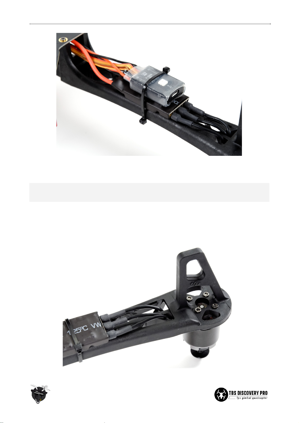
● Feed the battery straps through the two slots in the battery compartment. Only one strap is really
necessary to provide adequate friction to keep the battery fastened.
Optional: Use different colored frame arms for the front and back pair to make it easier to identify the
orientation of the quadcopter in the air.
Motors
● Mount the brushless motors to the frame arms using the supplied M3x6.5mm hex screws. There is
no need to add an X-mount to the motors. Apply a small drop of medium threadlock to a secure the
base. Feed the motor wires through the frame arm comb-pattern to minimize clutter.
26
Page 30
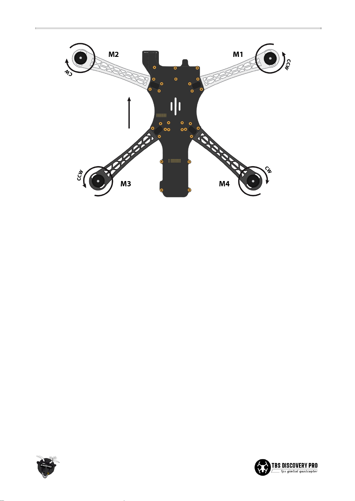
● Plug in the bullet-connectors to the speed controllers. Swap any two wires to change the direction of
rotation if they do not rotate as shown below. See the image above for the most commonly used
motor setup (e.g. NAZA-M.)
27
Page 31
Top plate
R/C control signal headers
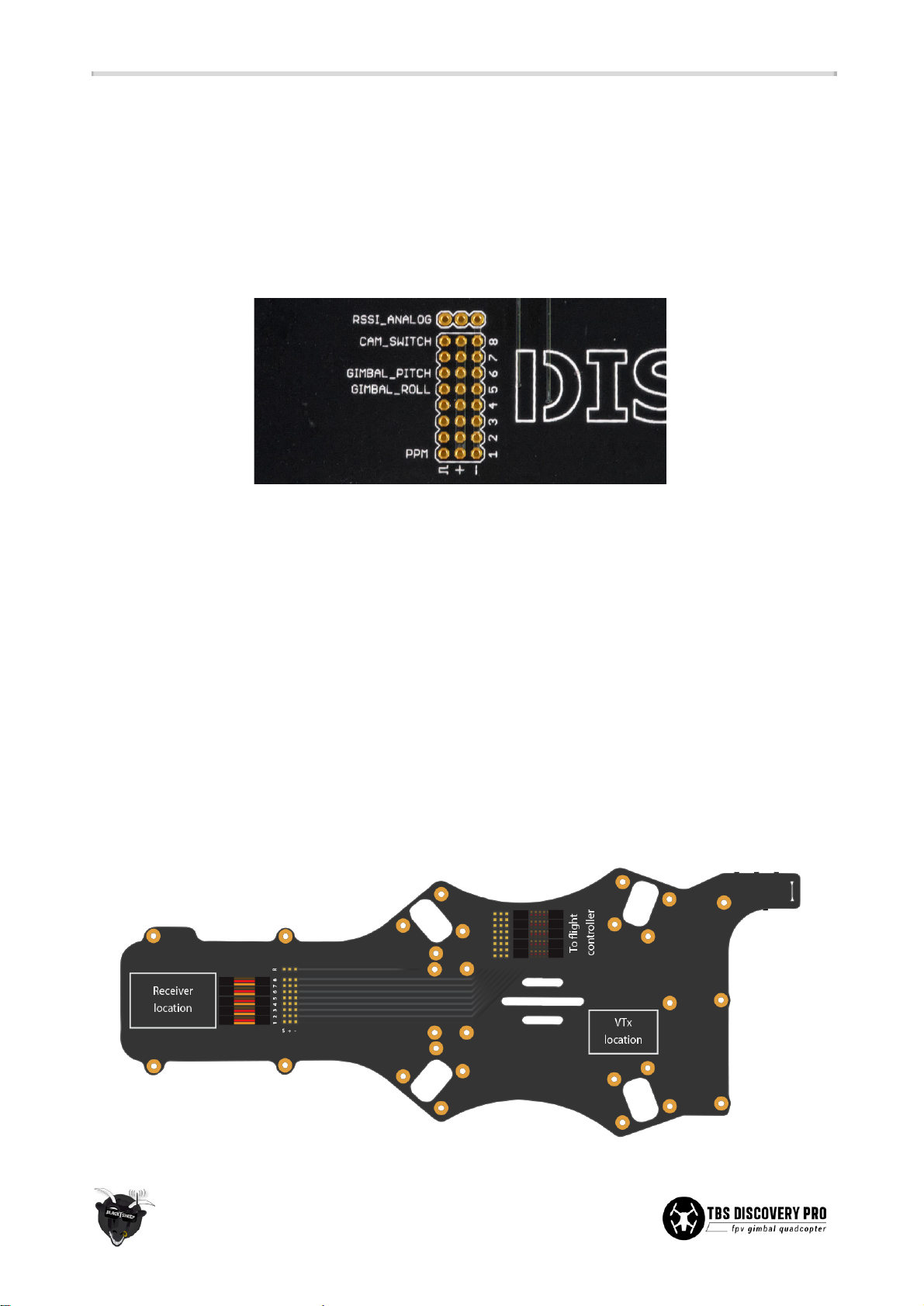
● To get a clean R/C receiver-to-flight controller wiring, it is recommended to use the header on the top
plate. There are 8 traces to support up to equally many PWM (Pulse Width Modulation) channels.
When using a PPM (Pulse Position Modulation) compatible receiver and flight controller, only one
trace (Channel 1) is used.
● Solder the supplied pin header to the 8x3-pads and the single 1x3-header to the separate RSSI pad.
Install the first header on the R/C receiver side (back-end) with the pins pointing up and, if you are
using PWM control signals, solder the second header with the pins pointing down (towards the
bottom plate/flight controller.) Use tape to keep the header in place while applying a reasonable
amount of solder to all of the pins while applying heat. The flux in the solder will make the solder
flow around the pins.
● The layout of the header is as follows:
○ channel 1 for PPM stream or channel 1 to 4 for PWM aileron/elevator/throttle/yaw control
○ channel 5 for PWM gimbal horizontal roll control (rarely needing adjustments)
○ channel 6 for PWM gimbal tilt pitch control
○ channel 7 for PWM flight mode selection (i.e. attitude, manual, GPS assisted)
○ channel 8 for PWM camera switch (i.e. fpv camera or GoPro feed)
○ a dedicated RSSI_ANALOG header for CORE OSD signal strength read-out
28
Page 32
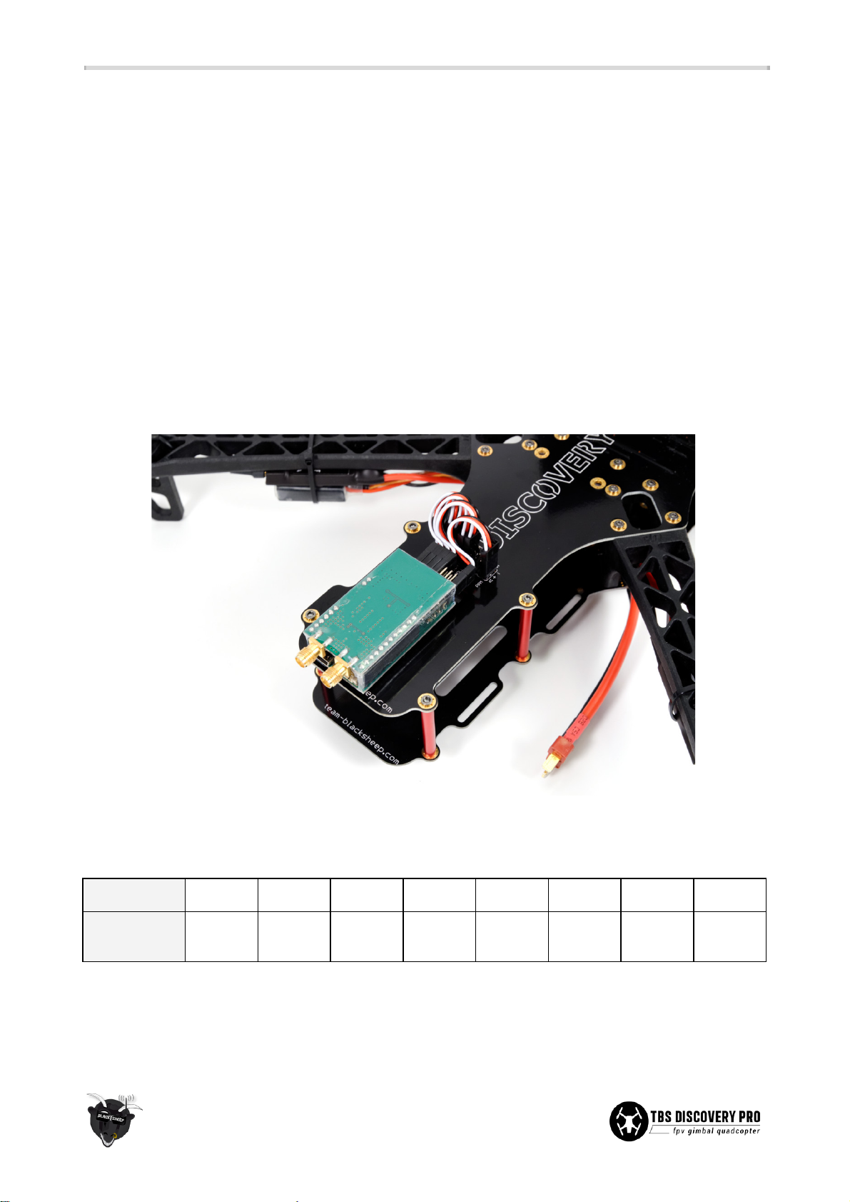
● The channels with a text label, i.e. PPM, GIMBAL_ROLL, GIMBAL_PITCH, CAM_SWITCH and
RSSI_ANALOG, has the signal pin (∏) hardwired directly to their respective electronics section on the
top frame (i.e. flight controller PPM break-out, gimbal controller roll/tilt, camera switcher, and CORE
RSSI signal). No further wiring is needed to enable those systems.
● Either gimbal channels and/or camera switch channel can be omitted if desired to free up channels
(e.g. to use a 6/7 channel PWM receiver.) But you will of course lose direct control over those
systems.
● See the “FPV gear and gimbal” in the electronics installation section for further details.
R/C receiver
● Plug in the short servo extensions on the header on the top plate and connect them to the R/C
receiver. Use a self-adhesive foam pad to mount the unit to the back-end of the top plate. Mount the
antenna(s) in a vertical and/or “V”-formation using nylon antenna tube(s).
● Channel 5, 6 and 8 pin headers can be used for other purposes (e.g., NAZA X1, X2) by disabling the
gimbal R/C mapping via SimpleBGC (BaseCam) and/or camera switcher via CORE Menu.
R/C receiver
Ch. 1
Ch. 2
Ch. 3
Ch. 4
Ch. 5
Ch. 6
Ch. 7
Ch. 8
Flight
controller
Aileron/
PPM
Elevator
Throttle
Rudder
Gimbal
Roll
Gimbal
Pitch
Flight
mode
Camera
switch
● When using the RSSI (Received Signal Strength Indication) signal from a compatible R/C receiver, use
the header labeled RSSI_ANALOG to supply the signal directly to the CORE. Or, leave the header
unused and connect the output to your OSD system of choice.
29
Page 33
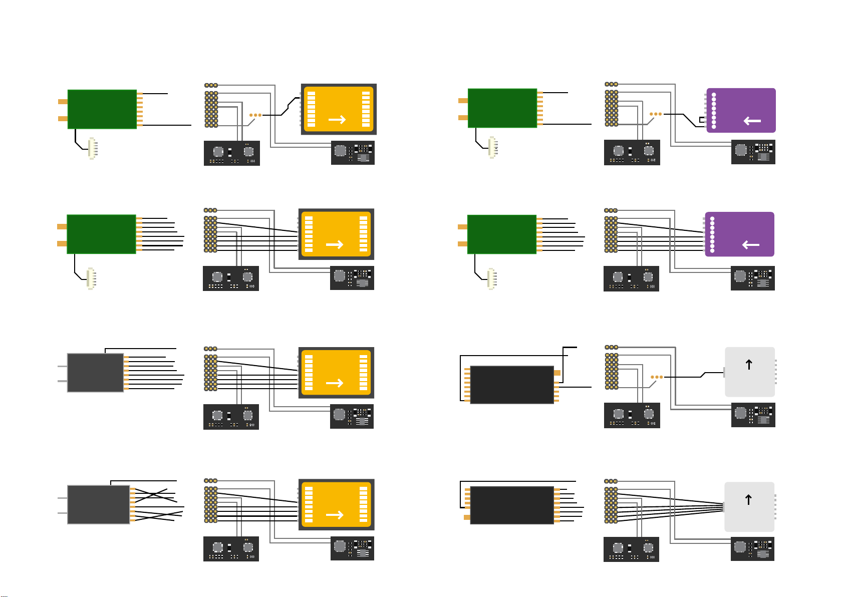
TBS DISCOVERY PRO - Common receiver and ight controller setups
EzUHF - NAZA - PPM - RSSI Link
R/C receiver
- Congure “Muxed PPM” on CH1 and the camera
switch (PPM 8) on CH8 in ImmersionRC Tools
EzUHF
CH8
CH7
CH6
CH5
CH4
CH3
CH2
CH1
EzUHF RSSI Link
- Enable “LINK” in the
“RSSI” CORE menu
source in SimpleBGC
- CORE prole switching
R/C pin header
RSSI analog
Camera switcher
Gimbal pitch
Gimbal roll
Gimbal controller
- Enable “PWM”
only supports PWM
PPM
EzUHF - NAZA - PWM - RSSI Link
R/C receiver
- Reset the servo mapping to default
in ImmersionRC Tools
EzUHF
CH8
CH7
CH6
CH5
CH4
CH3
CH2
CH1
EzUHF RSSI Link
- Enable “LINK” in the
“RSSI” CORE menu
source in SimpleBGC
R/C pin header
RSSI analog
Camera switcher
Flight mode
Gimbal pitch
Gimbal roll
Rudder
Throttle
Elevator
Aileron/PPM
Gimbal controller
- Enable “PWM”
Futaba/Hitec - NAZA - PWM - Analog RSSI
RSSI not ocially supported by Futaba/Hitec/Graupner
- Enable “ANALOG” in the “RSSI”
CORE menu
Futaba/
Hitec
8
7
6
5
4
3
2
1
R/C receiver
R/C pin header
RSSI analog
Camera switcher
Flight mode
Gimbal pitch
Gimbal roll
Rudder
Throttle
Elevator
Aileron/PPM
Gimbal controller
- Enable “PWM”
in SimpleBGC
PPM
Flight controller
- Enable “PPM” in NAZA Assistant
X3
X2
X1
U
R
T
E
A
CORE (Camera switcher)
- Enable “SWITCH”
in the “CAM” menu
Flight controller
- Enable “Traditional” in NAZA Assist.
X3
X2
X1
U
NAZA
R
T
E
A
CORE (Camera switcher)
- Enable “SWITCH”
in the “CAM” menu
Flight controller
- Enable “Traditional” in NAZA Assist.
X3
X2
X1
U
NAZA
R
T
E
A
CORE (Camera switcher)
- Enable “SWITCH”
in the “CAM” menu
NAZA
EzUHF - APM2 - PPM - RSSI Link
R/C receiver
- Congure “Muxed PPM” on CH1 and the camera
switch channel to output CH8 in IMRC Tools
EzUHF
CH8
CH7
CH6
CH5
CH4
CH3
CH2
CH1
EzUHF RSSI Link
- Enable “LINK” in
the “RSSI” CORE menu
source in SimpleBGC
- CORE prole switching
R/C pin header
RSSI analog
Camera switcher
Gimbal pitch
Gimbal roll
Gimbal controller
- Enable “PWM”
only supports PWM
PPM
EzUHF - APM2 - PWM - RSSI Link
R/C receiver
- Reset the servo mapping to default
in ImmersionRC Tools
EzUHF
CH8
CH7
CH6
CH5
CH4
CH3
CH2
CH1
EzUHF RSSI Link
- Enable “LINK” in
the “RSSI” CORE menu
R/C pin header
RSSI analog
Camera switcher
Flight mode
Gimbal pitch
Gimbal roll
Rudder
Throttle
Elevator
Aileron/PPM
Gimbal controller
- Enable “PWM”
in SimpleBGC
DragonLink - OpenPilot - PPM - Analog RSSI
R/C receiver
- Ealier models use CH9 for PPM
Congure CORE to use analog RSSI
CH1
CH2
CH3
CH4
DragonLink
CH5
CH6
CH7
CH8
RSSI
CH12
CH11
CH10
CH9
source in SimpleBGC
- CORE prole switching
R/C pin header
RSSI analog
Camera switcher
Gimbal pitch
Gimbal roll
Gimbal controller
- Enable “PWM”
only supports PWM
PPM
PPM
PPM
Flight controller
- PPM: Use a jumper over the
elevator and aileron channels
Aux4
8
Aux3
7
Aux2
6
Aux1 F. mode
5
Rudder
4
Throttle
3
Elevator
2
Aileron
1
CORE (Camera switcher)
- Enable “SWITCH”
in the menu
Flight controller
- Secret trinket n/t
Aux4
8
Aux3
7
Aux2
6
Aux1 F. mode
5
Rudder
4
Throttle
3
Elevator
2
Aileron
1
CORE (Camera switcher)
- Enable “SWITCH”
in the menu
CORE (Camera switcher)
- Enable “SWITCH”
in the menu
APM2
APM2
Flight controller
- Secret trinket n/t
OpenPilot
ReceiverPort
Spektrum/JR - NAZA - PWM - Analog RSSI
RSSI not ocially supported by Spektrum/JR
- Enable “ANALOG” in the “RSSI”
CORE menu
Spektrum
/JR
AUX3
AUX2
AUX1
GEAR
RUD
ELE
AIL
THR
R/C receiver (Tx set up as airplane)
R/C pin header
RSSI analog
Camera switcher
Flight mode
Gimbal pitch
Gimbal roll
Rudder
Throttle
Elevator
Aileron/PPM
Gimbal controller
- Enable “PWM”
in SimpleBGC
Flight controller
- Enable “Traditional” in NAZA Assist.
X3
X2
X1
U
NAZA
R
T
E
A
CORE (Camera switcher)
- Enable “SWITCH”
in the “CAM” menu
DragonLink - OpenPilot - PWM - Analog RSSI
R/C receiver
- Congure CORE to use analog RSSI
CH9
CH10
CH11
CH12
RSSI
DragonLink
CH8
CH7
CH6
CH5
CH4
CH3
CH2
CH1
R/C pin header
RSSI analog
Camera switcher
Flight mode
Gimbal pitch
Gimbal roll
Rudder
Throttle
Elevator
Aileron/PPM
Gimbal controller
- Enable “PWM”
in SimpleBGC
CORE (Camera switcher)
- Enable “SWITCH”
in the menu
Flight controller
- Secret trinket n/t
OpenPilot
ReceiverPort
Page 34
● (EzUHF Rx 8ch only) The CORE can decode the digital RSSI signal from the receiver via the separate
“OSD Link” port and display RSSI on each of the two antennas and overall signal quality (including
packet loss) of the R/C uplink. A 5-pin Molex cable is included which plugs into the EZUHF_RSSI_LINK
connector on the top plate. For this feature to work the CORE’s RSSI setting needs to be set to “LINK”.
There is no need to calibrate the RSSI in this scenario.
Propellers
● Before adding the propellers it is a good idea to be sure they are balanced, as mentioned later on. To
avert any chance of injury, leave the propellers off until the flight controller configuration has been
completed.
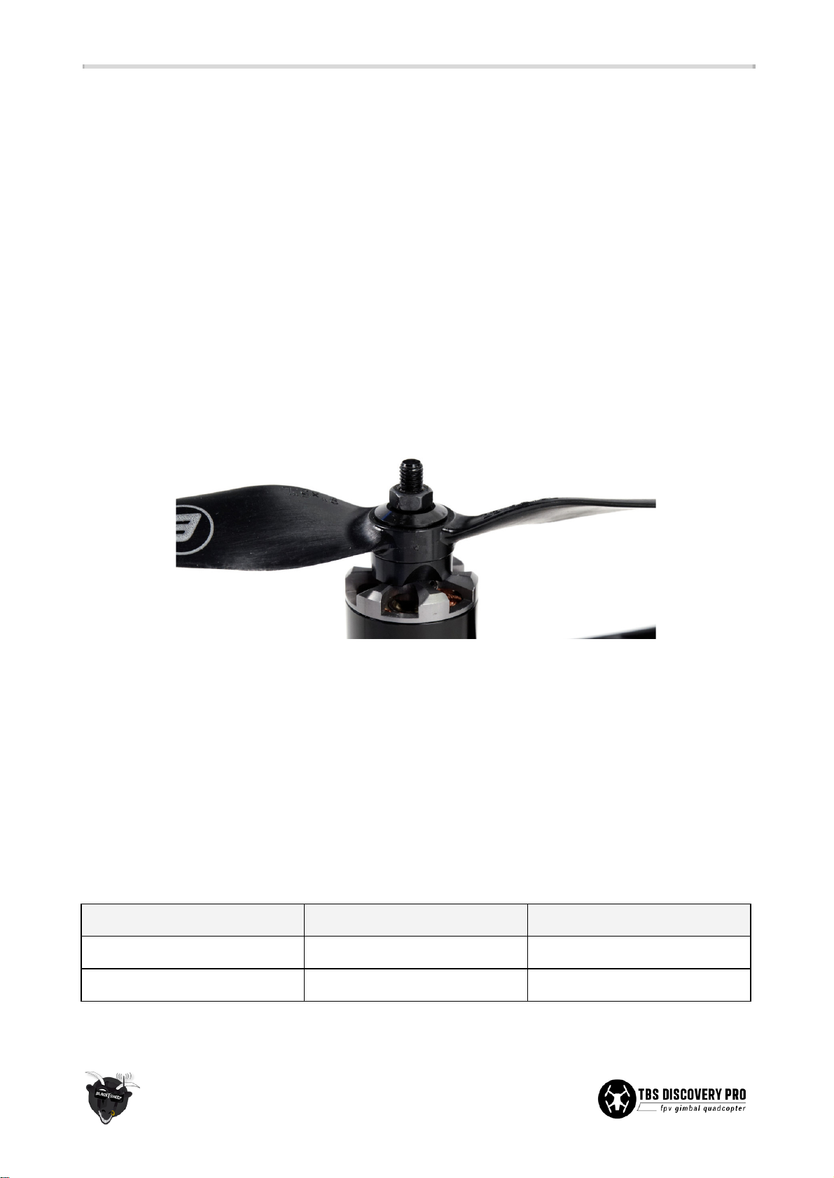
● The only recommended propeller installation method is to use a precisely manufacturer prop
adaptors (never prop-saver with o-ring.) The layering should be as follows;
prop adaptor, optional
reduction ring, propeller
,
washer
and (
lock) nut
. You can skip any bell screw as it may add
unnecessary vibrations.
● The TBS 900kV motors have a 5mm prop shaft. This is compatible with Graupner 9x5-inch propellers.
For Graupner 10x5-inch propellers you will need aluminium 8mm-to-5mm reduction spacers
available separately.
● Try to match the motor and propeller to suit your particular need. For extended flight time try to
achieve optimal efficiency. For agile-flight look at a responsive combination. Our general
recommendations are listed in the table below.
● A thumb of rule would be that smaller props equals less flight time, and higher kV motors equals
smaller props or lower battery cells count (than the reference below.) Note that 10-inch is the
maximum propeller size that can fit on the DISCOVERY PRO.
Motor type
Propeller
Flight characteristic
TBS 900kV brushless motor
9x5-inch Graupner type
responsive, locked in
10x5-inch Graupner type
long flight time
30
Page 35
Bottom link
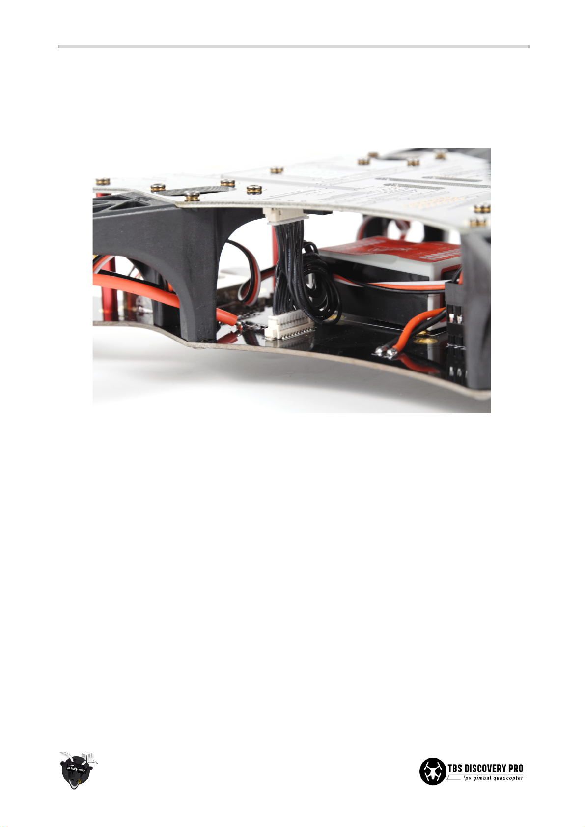
● Attach the the 9-pin plate-to-plate bottom link cable to the designated connector on the bottom
plate. It carries carries current sensor signal, Vbatt, ground, +V5, +V12 up and PPM down. When
closing the frame, plug in the cable to the corresponding connector on the top plate.
31
Page 36
FPV and gimbal gear
The FPV gear is designed to be installed on the front section of the frame to achieve as much separation
between the R/C- and FPV-radio environment as possible. Keep in mind that the former is listening while the
latter is broadcasting. The quieter the receiving conditions are, the better range and system reliability will be.
CORE power supply
● To eliminate noise from causing problems on the FPV-side of the system, a properly filtered TBS
CORE is integrated right into the frame. It is made to provide selectable 12V (0.65A max.) or 5V (2A
max.) to the video transmitter and FPV camera via on-board solder pads. The CORE and R/C power
rails are completely separated and is by design not dependent on either system in order to function
properly. Interference and noise from the driver train is isolated nicely from the rest of the
electronics on the frame.
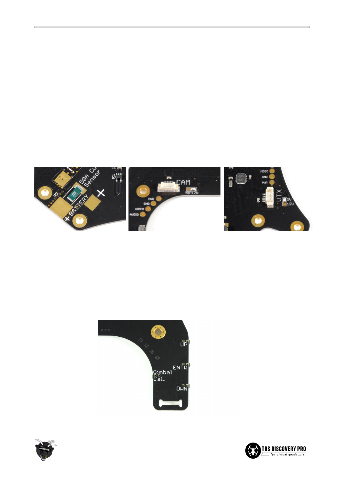
● Configure the required voltage for your FPV gear by soldering a dab to the pads labeled VTX and CAM
on the top plate (as shown in the pictures above.) The frame already comes pre-configured for 5V
video transmitters and 12V FPV cameras. Adjust the output voltage by soldering the middle pad and
either side pad for 12V or 5V. Do not solder all three pads (short-circuit.)
● When you first power up the CORE, it will ask you to cycle through the buttons “DWN”, “ENTR” and
“UP” accordingly to verify that they work properly. This is also a good time to get familiar with the
CORE menu layout.
32
Page 37
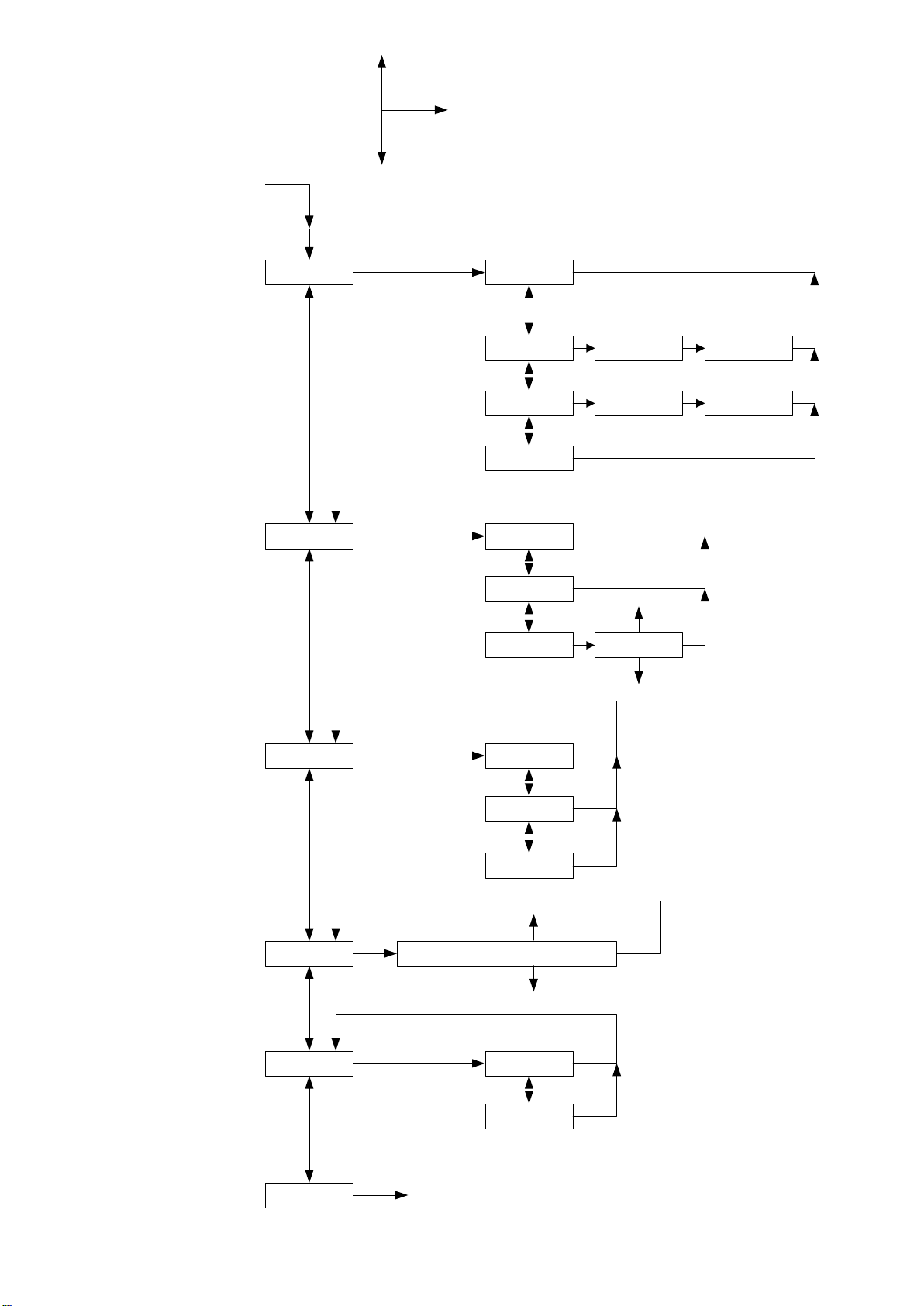
CORE menu layout
Button Enter
use up
Page 38
TBS CORE PNP PRO installation diagram for TBS DISCOVERY PRO
PRO
ENTR
DWN
UP
Gimbal
cal.
Dec. 2014 - by ivc.no/tbs
RSSI_ANALOG
CAM_SWITCH
GIMBAL_PITCH
GIMBAL_ROLL
PPM
COMPASS
GPS
CH1
CH2
CH3
CH4
CH5
CH6
CH7
CH8
EzUHF receiver (if used)
DISCOVERY
1 2 3 4 5 6 7 8
S + -
TBS GPS/COMPASS module (optional)
Note: no power or audio lead
(available separately)
Caution: do not use the normal CAM-cable to
connect the CORE PRO to the DISCOVERY PRO
(two voltage sources conict)
Left side
Bottom plate
TBS CORE PNP PRO unit
UP ENTER DN
CAM
BST
RSSI
BST
TBS CORE
PNP PRO
VTX
LINK
B-PWR
USB
VTX
Note: mount unit in center of the bottom
plate, on top of the ight controller (NAZA),
or on the left side on the bottom plate
5V 12V
VTX
Note 1: disable the on-board DISCOVERY PRO
OSD in the CORE menu using the buttons on
the top plate - else the OSDs will overlap.
Pwr
Gnd
Video
Audio
Top plate
Pitch
Roll
IMU/GoPro
Note 2: the pilot camera and GoPro HD camera
switching is still performed by the on-board
TBS DISCOVERY PRO CORE.
Note 3: since there are now essentially two
COREs, you can solder the jumper on the GoPro
adapter board to enable charging at 1A rate.
Note 4: to save weight and bulk, consider
removing the plastic case for the current
sensor and connectors on one or both sides.
Bottom link
CAM
5V 12V
From battery
VTX2
Gnd
Vbat
Video
VTX2 Switch
GP Out Sel
XT60
PWR
XT60
IN
BST
PWR
OUT
XT60
XT60
Existing battery lead
Pwr
Gnd
Video
Audio
Pilot camera
Current sensor
Page 39
● The solder pads next to the sockets can be used to connect your gear, but try to connect your FPV
camera and video transmitter via the Molex connectors on the board. With that, you will not risk
ripping off the pads from the frame when pulling too heavy on a cable. Modify our cable harness
when using other than TBS suggested gear.
● A pre-installed tin shield makes the DC-to-DC switching voltage conversion part of the CORE isolated
from the rest of the electronics on frame.
● A full menu layout of the CORE menu system is available as an appendix to this manual.
Pilot camera
● Use the supplied camera plate to mount the pilot camera. The mounting pattern is designed to be
compatible with most standard 32x32 mm board cameras. You might need to break-away excessive
board support. Either use two small zip-ties, rubber bands or four M2x15mm screws and nuts (not
supplied) to mount the camera (use threadlock.)
● Plug in the cable connector for the camera and insert the tabs on the top and bottom of the camera
frame in the corresponding routed gaps on the frame. For a secure mount, you can add solder to the
three exposed solder spots, or leave it for easy hot swapping in the field.
33
Page 40
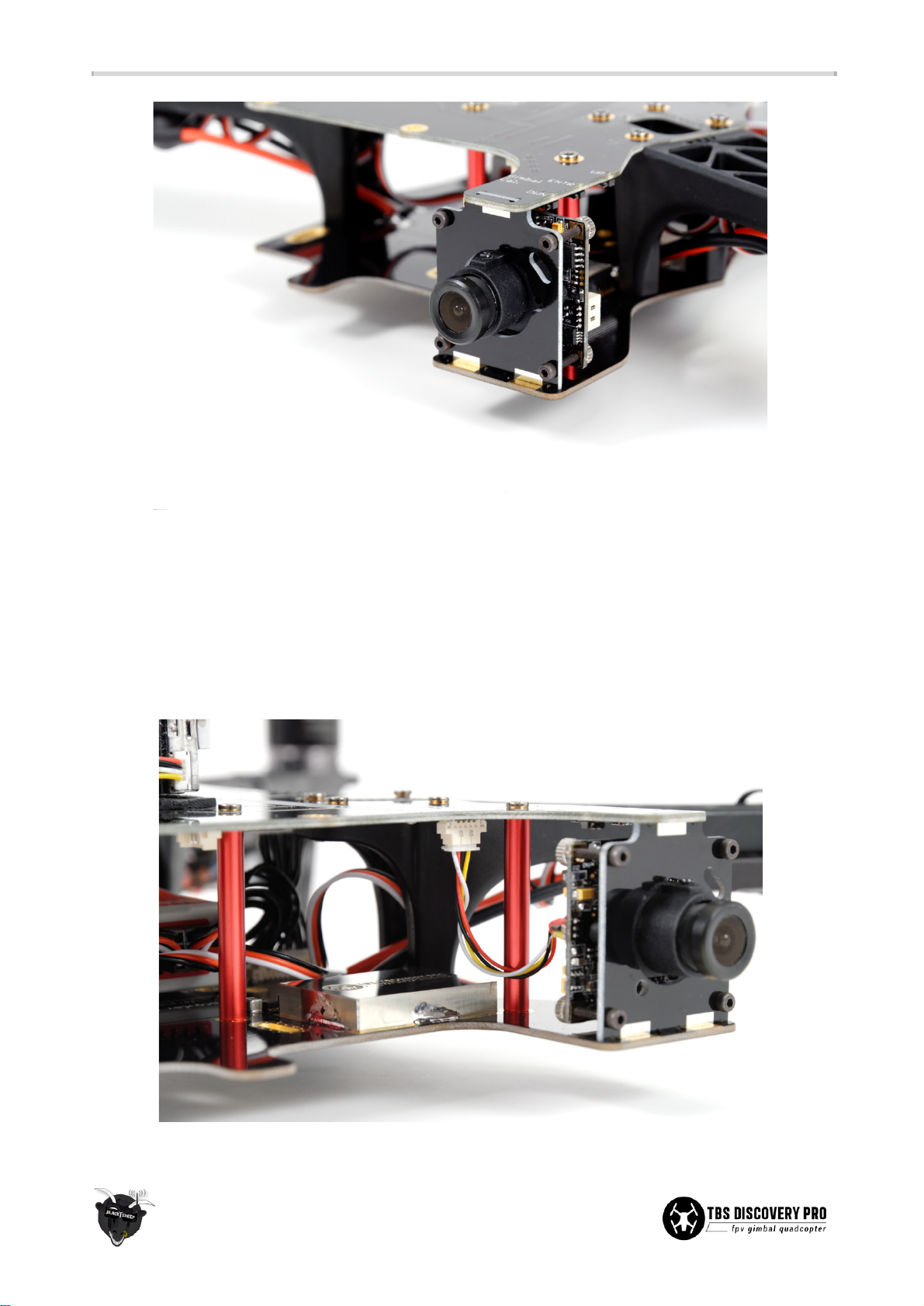
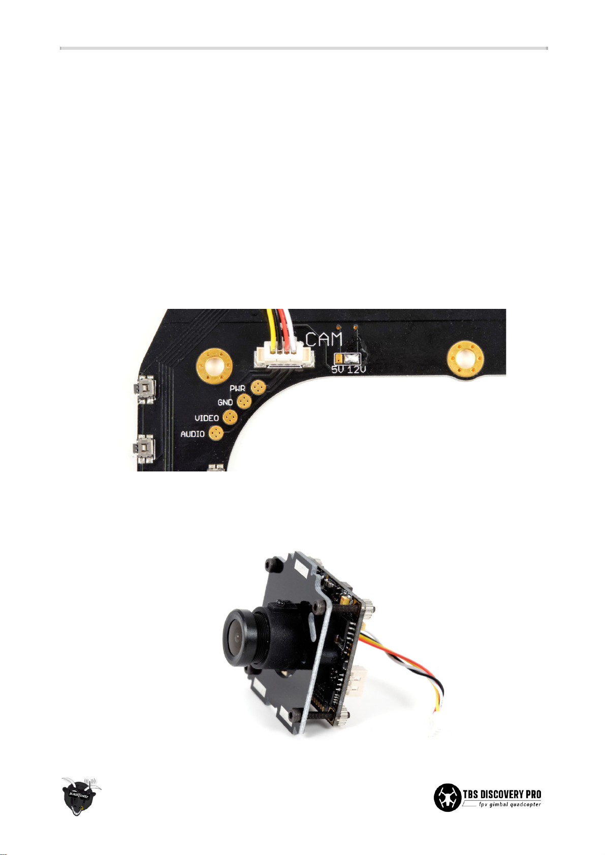
● Decide whether you can use the supplied wires and connector socket on the top frame or connect
the camera and video transmitter via the round solder pads. The supplied picoblade Molex cable “5V
VTx” are designed to work with the TBS GREENHORN, TBS ROOKIE, Lawmate video transmitters, and
the supplied “12V CAM” cable with the TBS59/TBS69 cameras respectively. You can of course modify
and solder the wires to suit your specific need. The connector wire color and signal arrangement is
shown in the picture previously, where yellow is video, white is audio, red is power and black is
ground.
34
Page 41
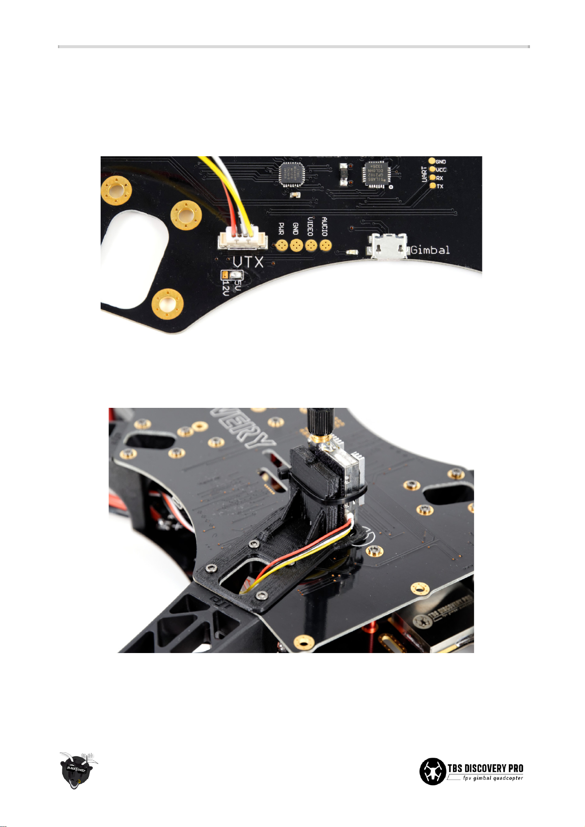
Video transmitter
● Put the video transmitter close to the front on the top plate. Use zip-ties and/or self-adhesive foam
pads to fit the transmitter. TBS offers a custom made mounting bracket for easy vertical install over
the front-right frame arm. To avoid possible video interference, be sure to use a foam or gel pad
between the frame and VTx unit to reduce exposure to vibration.
● The kit includes a small JST cable which is compatible with Lawmate 500mW VTx as well as our TBS
GREENHORN and TBS ROOKIE. For FatShark VTx you need to cut the cable and solder your FatShark
cable onto it. The connector wire color and signal arrangement is shown in the picture above.
● Powerful video transmitters, such as the ImmersionRC 5.8GHz 600mW or more powerful VTx, must
be powered directly from the bottom frame (small +/- pads) to avoid overdriving the CORE. Test this a
few minutes on the ground and verify that the CORE does not reboot which indicates a thermal
protection shutdown/overcurrent.
35
Page 42
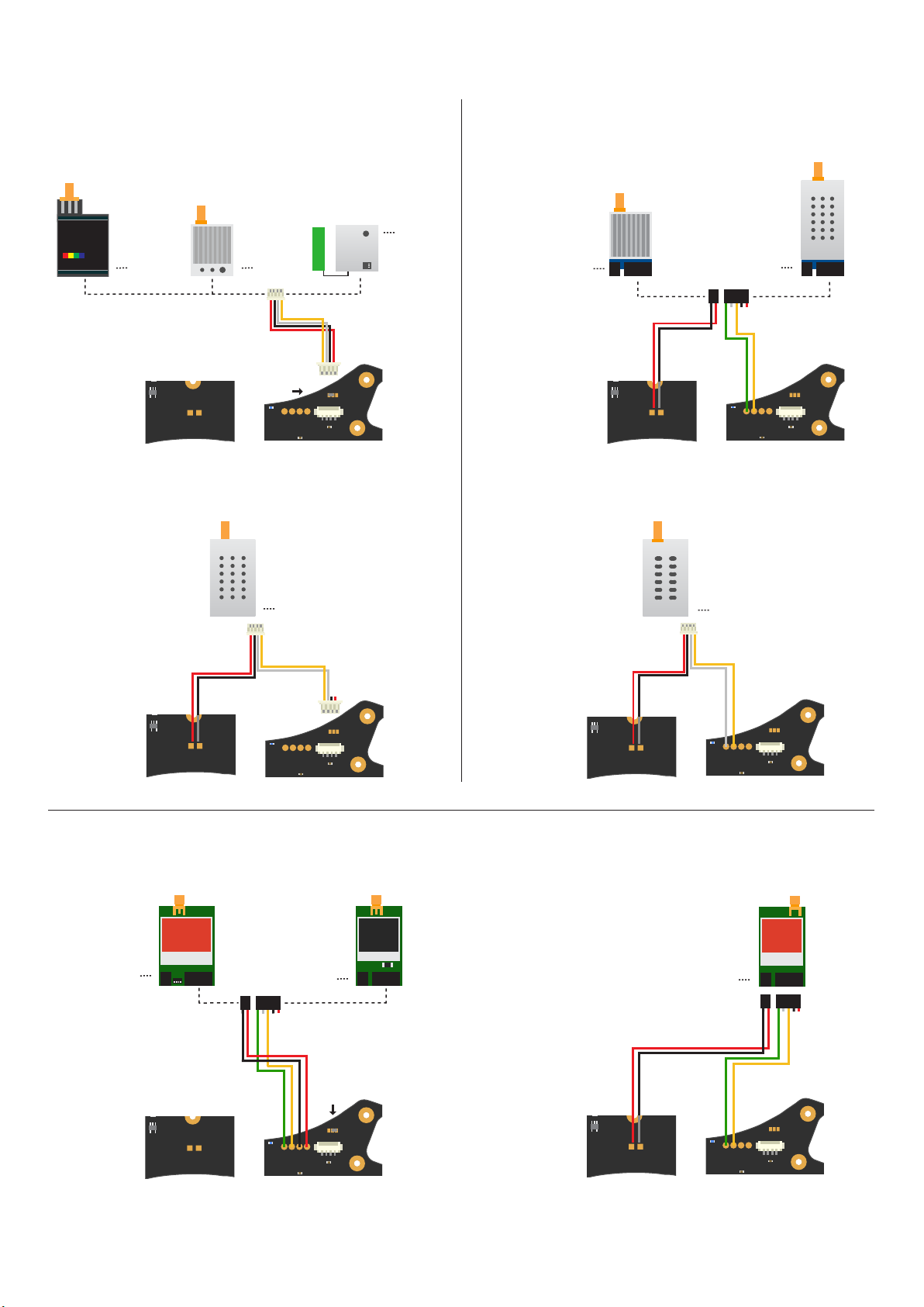
TBS DISCOVERY / DISCOVERY PRO - Video transmitter (VTx) setups
--
+
--
PPM
+
--
S + -
DISCOVERY PRO
Top Link
+
Pitch
--
+
--
PPM
+
--
S + -
DISCOVERY PRO
Top Link
+
Pitch
--
+
--
PPM
+
--
S + -
DISCOVERY PRO
Top Link
+
Pitch
--
+
--
PPM
+
--
S + -
DISCOVERY PRO
Top Link
+
Pitch
--
+
--
PPM
+
--
S + -
DISCOVERY PRO
Top Link
+
Pitch
--
+
--
PPM
+
--
S + -
DISCOVERY PRO
Top Link
+
Pitch
rev. Feb 2014 - by ivc.no/tbs
TBS/Lawmate VTx
· 1.2G 500mW
· 2.4G 100mW, 200mW, 500mW
· 5.8G 25mW (TBS Greenhorn), 200mW (TBS Rookie), 500mW (TBS Boss)
Supply voltage: 5.0-5.5V (all)
TBS 5G
VTX
Battery voltage
· 1.2G 1000mW
· 2.4G 1000mW
VID - Yellow
AUD - White
GND - Black
5V - Red
5V - Red
GND - Black
AUD - White
VID - Yellow
5V
--
+
5V 12V
!
VTX
Pwr
Gnd
Video
Audio
VID - Yellow
AUD - White
GND - Black
5V - Red
Boscam VTx
· 2.4G 500mW
· 5.8G 200mW, 400mW, 500mW
Supply voltage: 12-14V (3S)
FatShark
5.8GHz
250mW
BATT - Red
GND - Black
AUDR - Green
AUDL - White
VID - Yellow
BATTOUT - Red
GND - Black
Connect directly
only on 3S baery*
Battery voltage
!
Racewood VTx
· 1.3G 500mW
Supply voltage: 12-14V (3S)
BATT - Red
GND - Black
AUDR - Green
AUDL - White
VID - Yellow
BATTOUT - Red
GND - Black
5V 12V
VTX
--
+
Pwr
Gnd
Video
Audio
Connect directly
only on 3S baery*
Battery voltage
!
--
+
FatShark/ImmersionRC VTx
· 5.8G 25mW, 250mW
Supply voltage: 6-16V (2S-4S)
GND - Black
BATT - Red
AUDR - Green
AUDL - Grey
VID - Yellow
GND - Black
5.8GHz
25mW
A/V Tx
5V Out - Red
Supply voltage: 12V
GND - Black
AUD - White
12V - Red
VID - Yellow
5V 12V
VTX
Pwr
Gnd
Video
Audio
Supply voltage: 7-17V (2S-4S)
GND - Black
BATT - Red
AUDR - Green
AUDL - Grey
VID - Yellow
GND - Black
Supply voltage: 9.5-12.5V (3S)
GND - Black
AUD - White
12V - Red
VID - Yellow
Connect directly
only on 3S baery*
Battery voltage
!
5V 12V
VTX
--
+
Pwr
Gnd
Video
Audio
· 5.8G 600mW
FatShark
5.8GHz
250mW
5V Out - Red
Supply voltage: 6-25V (2S-6S)
GND - Black
BATT - Red
AUDR - Green
AUDL - Grey
VID - Yellow
GND - Black
5.8GHz
600mW
A/V Tx
5V Out - Red
--
+
12V
5V 12V
VTX
Pwr
Gnd
Video
Audio
Battery voltage
Note: Connecting a video transmitter directly to a shared battery source
may induce interference on the video image. Consider adding a lter
between the solder pad and video transmitter.
!
5V 12V
Battery voltage
--
+
* On 4S+ setups where 12V is not available, consider using a dedicated
TBS CORE PNP to supply power to the video transmitter.
VTX
Pwr
Gnd
Video
Audio
Page 43
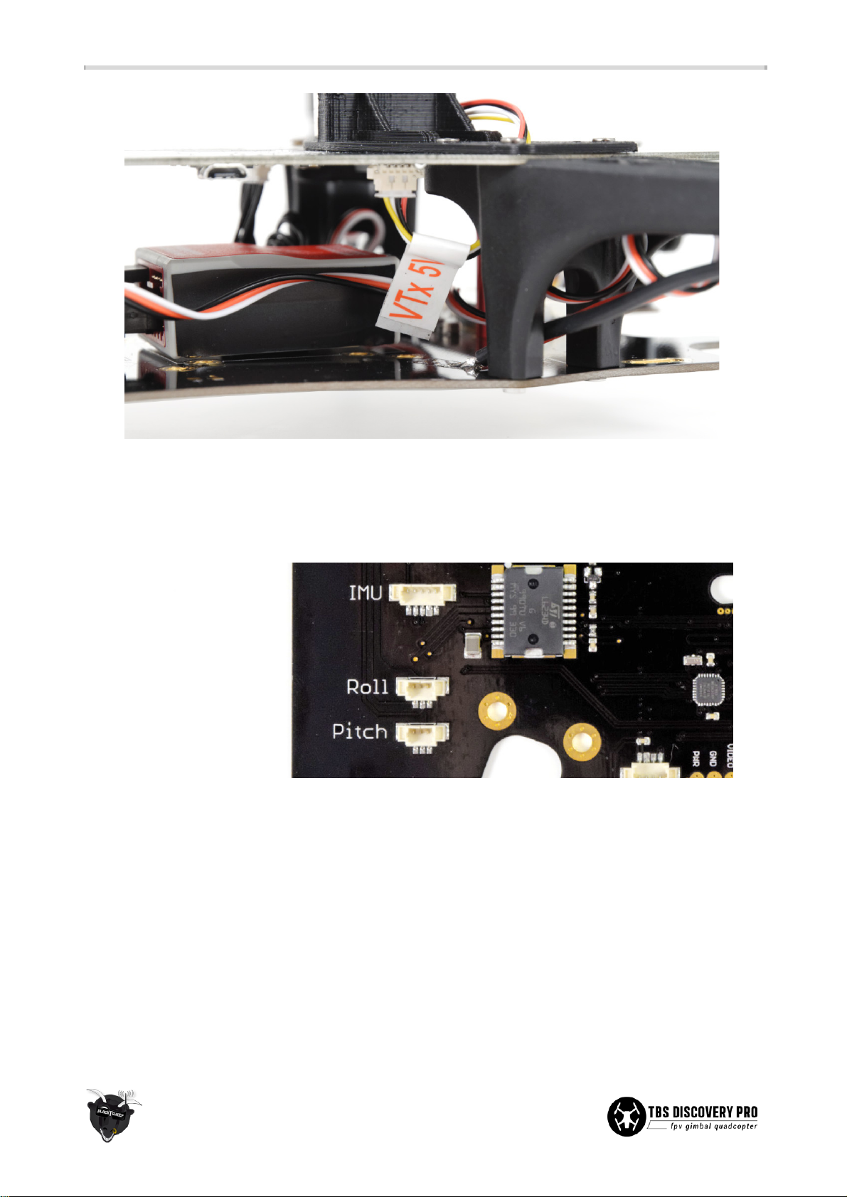
Brushless gimbal controller
● Plug in the 3 Molex cables for the pitch- and roll-motors, as well as the IMU board, into the
connectors labeled “PITCH”, “ROLL”, and “IMU” located near the front on the top plate.
● The controller comes pre-configured with PID gains which are fine-tuned for use with a GoPro HD
Hero3 and no additional accessories (lens protection or housing.) Tuning may be necessary (PID,
power) when using an older GoPro model or different add-ons. Also make sure to balance both axis
by moving the GoPro back or forth until it stays still independent of how you rotate/leave it.
● Additional configuration can be done using the SimpleBGC software package via the micro USB
connector on the right-side of the top frame. The CORE uses dual profile switching (described later in
the manual) which means that all essential flight tuning should be done in both profiles.
● The gimbal controller has two dedicated channels (RC_PITCH, RC_ROLL) brought out on the top plate
R/C header (channel 5 and 6) which can be used to position the GoPro image. This means that you
can assign a knob or slider on the radio to control pitch and roll of the gimbal.
36
Page 44

● If the camera gimbal is not level at start-up, move the gimbal and quad to a perfectly level position
(use a bubble leveler) and press the “GIMBAL CAL.” button on the top plate for 3-5 seconds until the
gimbal motors release. Wait for the blue LED to stop blinking and motors to lock again. Ensure that
the gimbal is perfectly still and straight during this calibration process.
● If the gimbal still drifts, recalibrate the sensors by turning any UHF or video transmitters, plugging in
power, connecting the frame to SimpleBGC, then propping up the gimbal so it stays level and still.
Then click “CALIB. ACC”, wait for it to finish, click “WRITE”, and then click “CALIB. GYRO” and “WRITE”.
● To further fine-tune the accelerometer, perform the 4 position calibration by setting both POWER to
0 and clicking “CALIB. ACC” after each time you position the gimbal
face forward
,
face down
,
face up
and
face backwards
. And only at the very end re-enable the POWER settings and commit the
calibration data by clicking “WRITE”. See the SimpleBGC manual for further details.
● Gyro calibration is very sensitive. If you are in a skyscraper, considering going to the ground floor for
this calibration. Do not use unstable surfaces, such as lightweight tables or wooden floors for
calibration. You only need to do this once in a while or when moving to an entirely new geographical
location. The calibration directly influences how well the gimbal performs.
● The gimbal controller is PPM compatible (no S.BUS support) and the channel 1 trace on the top plate
is integrated directly to the controller chip. To enable PPM gimbal, you need to close the solder pads
labeled “PPM GIMBAL” on the top plate, enable “PPM-Sum” and assign the right channels via the
SimpleBCG software. Remember to remove any servo-cables between the receiver and the header
channel 5 and 6, as any PWM signal would cause conflict.
● Note that in PPM mode, the CORE can not switch profiles because it relies on the gimbal controller to
be PWM configured. We suggest that you use a channel on your radio to switch profiles.
Camera switcher
● Switching video downlink feed is now possible via a dedicated R/C channel on the radio, e.g., a
2-position toggle switch. Connect a servo-cable from the receiver to the R/C header (channel 8). The
video switcher will change input when the PWM-period passes the 1520µs center point (50%). No
further sub-trim should be necessary. The failsafe setting depends on your receiver configuration.
● To enable the camera switcher functionality (off by default), press the “ENTR” button on the top plate
for 4-5 seconds and toggle to the “CAMERA TYPE" menu and select "SWITCH".
● When using PPM for R/C and/or gimbal control, the camera switching still has to be hooked up to
PWM. Fortunately, most receivers still output PWM on the remaining receiver pins when in PPM
mode. It only requires one additional servo-cable to CAM_SWITCH (ch8) to enable switching.
● Set the GoPro recording mode to match your FPV camera; 25p/50p equals PAL, 30p/60p equals NTSC.
This allows for faster transitions and no garbled screen because the viewing device (display, goggles)
does not need to switch video format.
● The GoPro jumper selector called “GP OUT SEL” is by default set to camera switcher and no further
soldering is necessary. For more information, refer to dual-pilot support later (advanced.)
37
Page 45
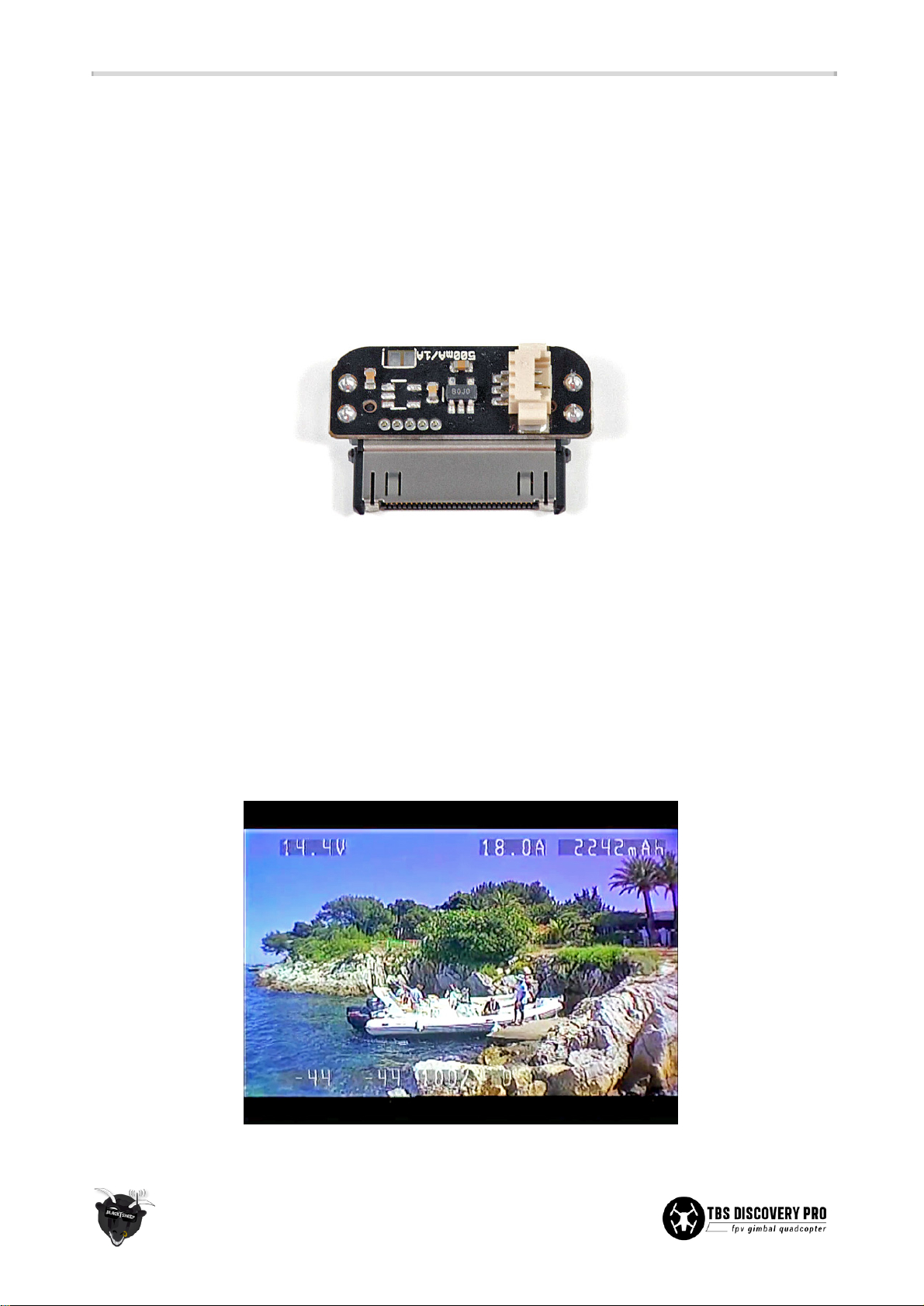
GoPro link
● With video switching now possible on the DISCOVERY PRO, the kit includes a small adaptor which
plugs into the GoPro 30-pin bus connector to provide video output and the possibility to charge the
GoPro while in flight. The charging is disabled by default and it is only recommended to enable the
“500mA/1A” solder bridge if you are certain the CORE will not be overloaded.
● After assembling the camera gimbal frame, plug in the 3-pin molex connector from the GoPro
adaptor to the gimbal IMU board. The IMU board just passes the video signal straight through to the
CORE/video switcher input, in an uncluttered fashion.
● (Advanced users only) There is even a component you can add on the board to be able to change the
charging rate from 1A to 0.5A continuous. To reduce the charging rate, order the IC part
NCP380HSN05AAT1G from Mouser or Digi-Key and solder the IC to the unoccupied pads on the
adaptor board (adequate soldering skills needed.)
OSD (On Screen Display)
● You can use the integrated OSD to get live readout on screen about the battery voltage (V), current
draw (A), total current consumption (mAh), receiver signal strength (%) and flight time
(minutes:seconds). This gives an essential overview of the system vitals while in flight.
38
Page 46
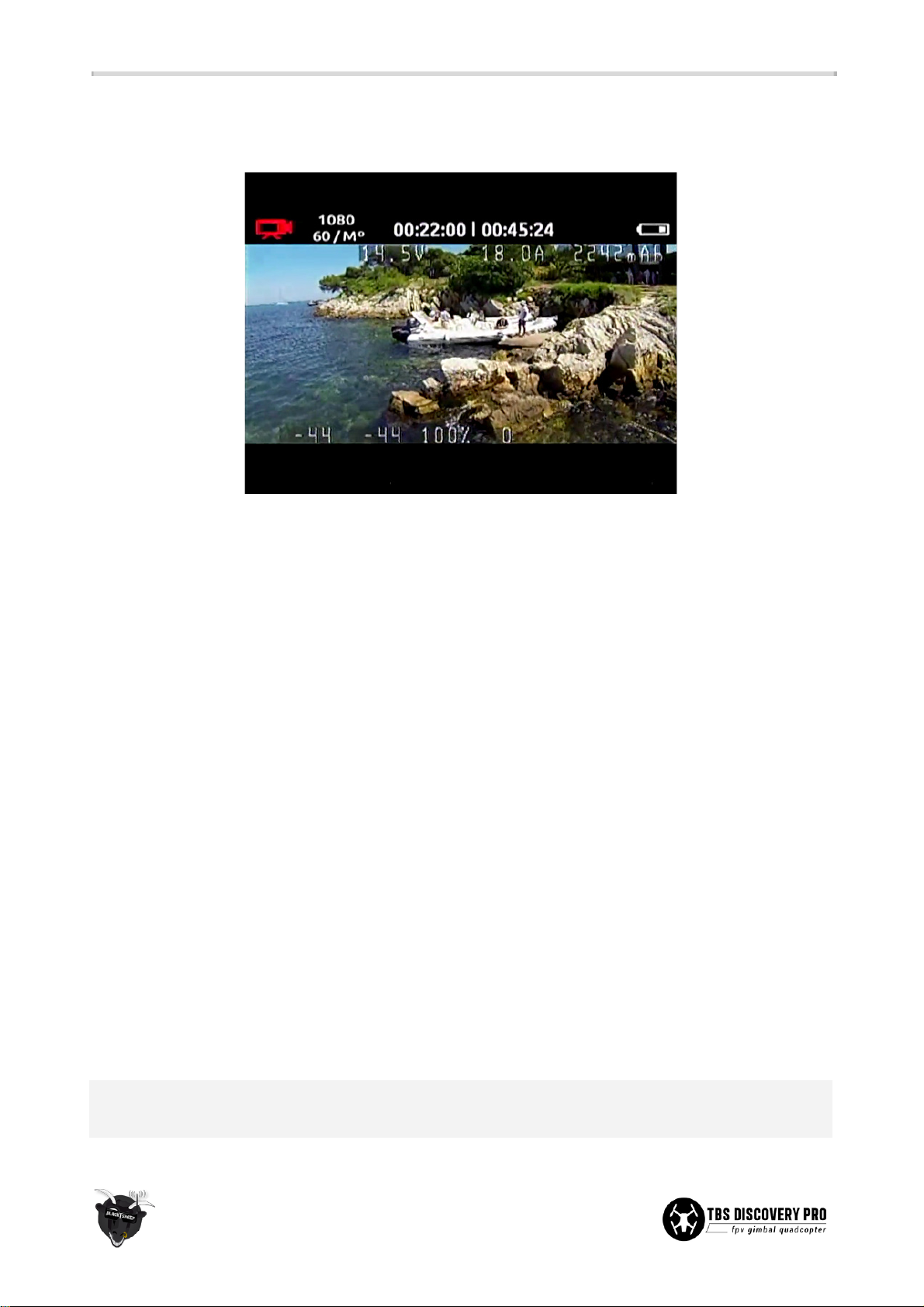
● The OSD is enabled by default, to disable it completely hook up video and press the “ENTR” button on
the top plate for 4-5 seconds, toggle to the “OSD" menu and select "OSD OFF".
● In the picture above the video feed is switched to the GoPro camera. Notice how the OSD adapts to
the GoPro margins. The EzUHF RSSI Link was used here, allowing additional details to be displayed
(diversity signal strength, link quality, packet loss.)
● As a side note, as soon as the RSSI figures get towards -90 or the link quality drops below 80%, it is a
good time to turn around (whichever comes first.)
● To read the R/C receiver signal strength (RSSI), connect a servo-cable between the receiver and the
designated RSSI_ANALOG header on the top plate. All major FPV R/C system vendors support either
analog or digital (PWM) RSSI output. For EzUHF owners, the CORE also supports “OSD Link”. Enter the
CORE menu to select the right RSSI type for your receiver and calibrate the max. (radio on) and min.
(radio off) value.
● The bottom plate includes an on-board current sensor in-line with the battery supply. Configure the
CORE to use the 50A current sensor. The sensor can also be tuned (in % increments) to more
accurately display current consumption (mAh), i.e. at the end of a flight if it was 1% too high, adjust it
down 1%. The same kind of adjustments can be made for the battery voltage (in 0.1V increments.)
The current sensor output is compatible with similar OSD systems. (Advanced users only) Limited
instructions on how to install the TBS CORE PRO on the PRO can be found later in this manual.
● Coupling current sensor and RSSI input directly on-board makes for a clutter-free OSD setup and
clean build. A full menu layout of the CORE is available as an appendix to the manual.
● Lastly, when all the R/C and FPV gear is installed connect the 9-pin top-bottom link cable and close
the frame. Use the remaining spacer and frame arm screws to secure the frame.
Note: Digital RSSI and Camera switch share the source pin with each other. If you use the Camera switch
you can only use analog RSSI or the link input from EzUHF receiver.
39
Page 47
Brushless gimbal stabilization
Integrated gimbal controller
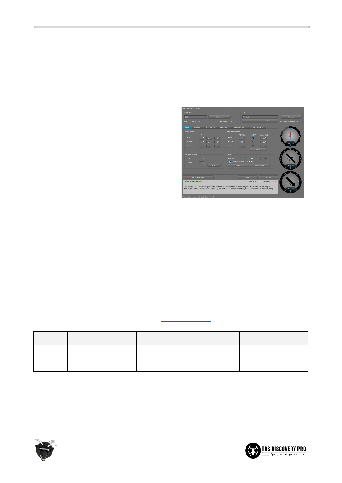
Setting up a gimbal the right way can be a daunting task, fortunately we licensed the SimpleBGC firmware
(AlexMos) and the SimpleBGC hardware layout from Viacopter. The controller has all the parameters pre-set
and gains tuned by TBS for a great out-of-the-box experience.
The gimbal controller is fully embedded into the frame
(a world's first), no soldering or software configuration
required. Just plug in the motors and IMU, and you are
good to go. The on-board USB port connects to your PC
for future firmware upgrades and custom configuration.
If you want to apply updates and make adjustments to
the gimbal, download the SimpleBGC and SiLabs CP210x
driver package (www.basecamelectronics.com), plug in
battery power, and connect the DISCOVERY PRO to a
Windows computer via a micro USB cable (e.g., from the
NAZA-M or a mobile phone.) Extensive details of the
brushless controller is available in the SimpleBGC
manual.
DISCOVERY PRO utilizes two profiles, one silent profile (Profile 1), to keep the gimbal quiet while on ground
and one noisy profile (Profile 2). The CORE MCU will detect when main motor starts (current consumption
>3A) and switch from the silent to noisy profile automatically. If you change something in SimpleBGC you
have to do the change on both profiles. If you want to change your in-flight values you have to do this on
Profile 2.
The following table shows the suggested PID and power controller gains for a GoPro HD Hero3&3+ mounted
on the gimbal. Download the factory settings from bit.ly/tbsprosettings.
Axis
P I D
Power
Poles
Inverted
FC Gain
Roll
12
0.1 9 175
14
Yes
0
Pitch
14
0.1 9 173
14
No
0
Other essential settings: Axis TOP to -Z, RIGHT to Y, skip gyro calibration at startup CHECK, gyro trust 100,
and PWM frequency to HIGH (silent) for Profile 1 and LOW for Profile 2, ROLL to RC_ROLL, PITCH to RC_PITCH,
CMD to EXT_ROLL, RC control ROLL to -30/30/CHECK/3/UNCHECK/10/0% and PITCH to
-90/90/CHECK/3/UNCHECK/10/0%.
40
Page 48
HD camera
The GoPro HD Hero camera is the most commonly used HD recording camera (as of writing) for sport
purposes, thanks to its wonderful high-quality picture and compact size. The TBS DISCOVERY PRO was
designed around the GoPro to take advantage of its great features.
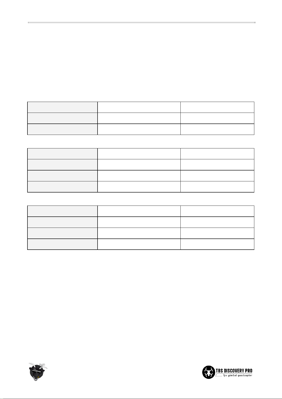
Consider using the GoPro settings in the tables below for “no-prop-in-view” footage. Adding a ND filter to the
front of the GoPro will also help slowing down the shutter speed and reduce “jello”.
GoPro HD Hero1:
Video format:
NTSC (or PAL to match pilot camera)
to get 30fps
Video resolution:
1080p 30fps (medium angle)
for 10x5-inch props
720p 30fps (wide angle)
for 9x5-inch props
GoPro HD Hero2:
Video format:
NTSC (or PAL to match pilot camera)
to get 30fps
Video resolution:
1080p 30fps
high quality video
Video angle:
Medium (127 degrees)
for 10x5-inch props
Wide (170 degrees)
for 9x5-inch props
GoPro HD Hero3/3+:
Video format:
NTSC (or PAL to match pilot camera)
to get 30/60fps
Video resolution:
1080p 60fps (or 30fps)
less chance of “jello”
Video angle:
Medium (127 degrees)
for 10x5-inch props
Wide (170 degrees)
for 9x5-inch props
41
Page 49
Center of Gravity optimization
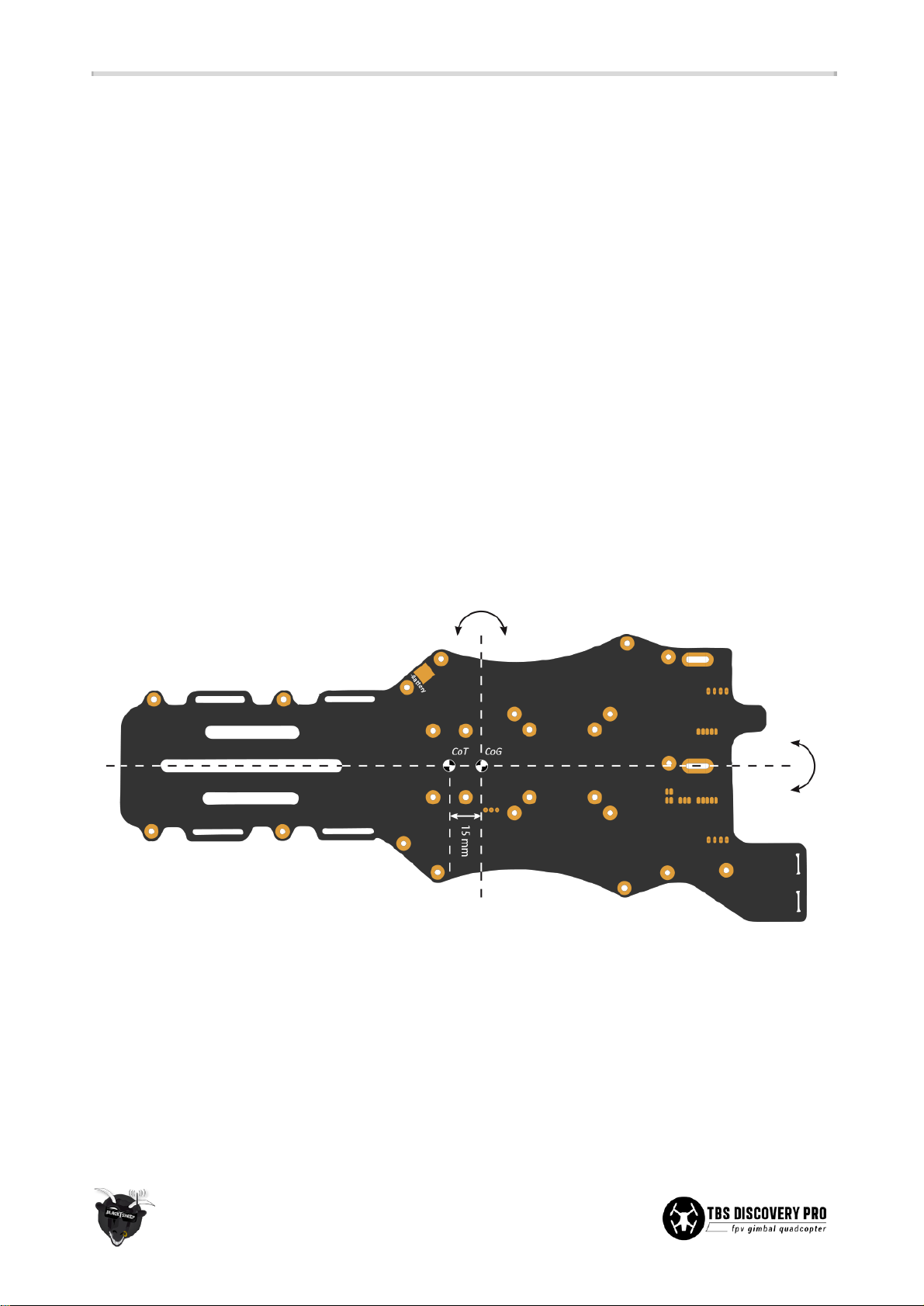
● A properly balanced multirotor will distributing the weight (mass) equally over the four motors. The
mark on the bottom plate is the Center of Thrust (CT, CoT) mark and the Center of Gravity (CG, CoG)
spot is 15mm forward of this mark. When holding the frame in the air at the CG spot it should ideally
be level and not dip to either side.
● After completing the build and loading up the frame, adjust the CG over the lateral (pitch) axis by
primarily moving the battery pack forward or backward. You might need to move the middle two
frame spacers to accommodate the battery. The CG over the longitudinal (roll) axis should be in the
center of the frame front-to-back and should only need slight adjustments.
● When the frame is out of balance some motors are going to have to work harder than others and you
will have less authority in a given axis due to the fact that one or more motors are already working
more than normally required. Small balance variations are countered very well by the flight
controller and should not cause any problems.
● If the quadcopter is too nose heavy it will bob up and down in forward flight and if it is too tail heavy
it will get very twitchy and hard to fly.
● As a side note, the flight controller does not need to be over the CG spot. It should be mounted in the
center of the white rectangular lines on bottom plate.
42
Page 50
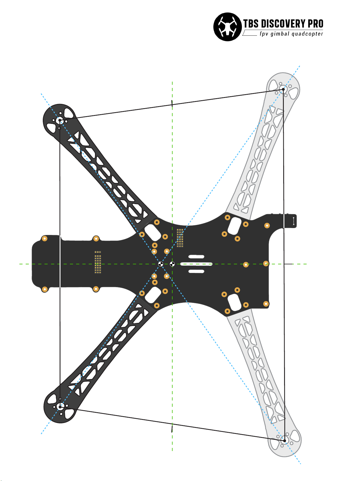
Median
Center of Gravity diagram
rev. 08. 2013 - by ivc.no/tbs
Center of Gravity
Center of Thrust
Median
Page 51
Dual-pilot support (ADVANCED USERS ONLY!)
Split dual-pilot support is possible in situations where a separate operator for piloting the quad and camera
is preferred. Extra equipment is needed for the extra video link and R/C control uplink (2-axis gimbal and yaw
adjustments.) Installation of the video transmitter and R/C receiver follows the same basic setup principles
described previously.
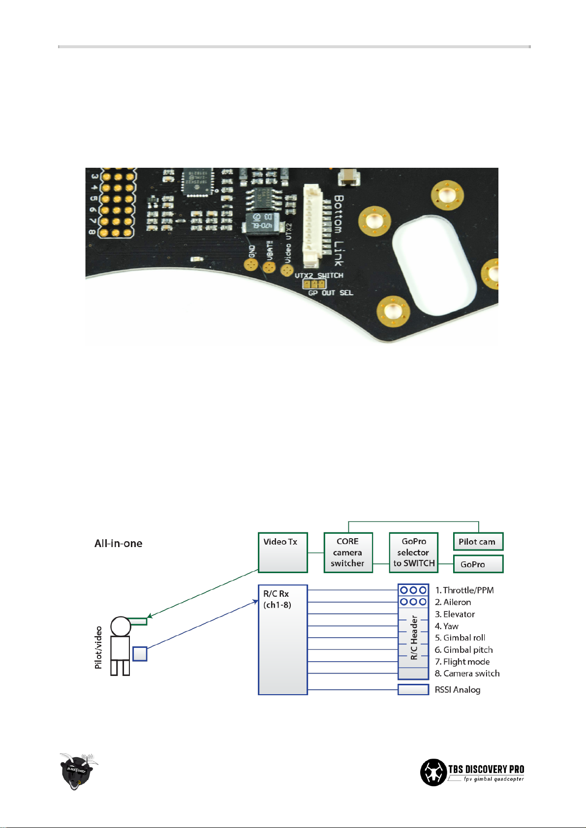
Connect the second video transmitter to location labeled VTX2 (GND, VBatt!!, Video.) The GoPro output
selector jumper works like this; the middle and right pads are connected by default from the factory,
transferring the Gopro image to the camera switcher. To use a second transmitter, cut the trace in between
the two pads. This can be done with a sharp knife. Use a multimeter to verify that the two pads are entirely
separated. Now connect the left and middle pad with a dab of solder, this diverts the GoPro image to the
Video pad.
● Single operator - For reference, the following diagram shows the normal “all-in-one” setup where
one operator maneuvers quad and controls video positioning.
43
Page 52
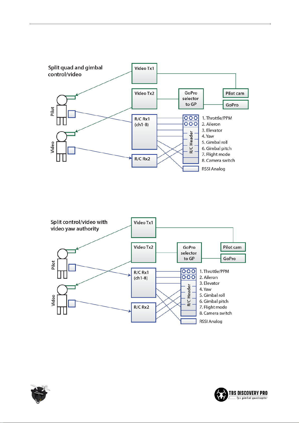
● Dual operator - Introducing a separate video operator for the gimbal roll and tilt control requires
one additional video transmitter and R/C receiver. Disable the video switcher, cut the trace between
the two “GP OUT SEL” jumper pads and solder the left pad to the middle.
● Dual operator with yaw authority - To give the video operator the ultimate freedom over framing
and picture positioning, swap the responsibility for yaw control over to the the video operator. This
requires good piloting skills and continuous communications back and forth to practice safe
maneuvering and flight.
44
Page 53

TBS CORE PNP PRO installation
The TBS CORE PNP PRO upgrade will make the DISCO PRO a full-featured quadcopter. You will be able to see
current power index, home direction, speed, altitude, distance to home, exact GPS coordinates and
notifications to assist you while flying. See the official CORE PRO manual for further details and setup,
available at team-blacksheep.com/tbs-core-pro-manual.pdf.
A full resolution diagram of the following procedure is available on the next page.
● By following these instructions you will end up with a dual CORE & CORE PRO setup where the video
out from the on-board CORE (with video switching) will feed into the CORE PRO, where the OSD
overlay will be applied. The on-board CORE can now be used to charge the GoPro HD camera at 1A, if
desired.
● The on-board CORE automatic gimbal profile switching (at >3A) will function as normal and no
change is necessary.
● First, enter the CORE menu via the buttons on the top plate and set CAM TYPE to SWITCH and OSD to
OSD OFF - to enable pilot<->GoPro camera switching and avoiding overlapping OSDs.
● Connect the GoPro and pilot camera as normal to the top plate (IMU/GoPro and CAM). Disconnect
the video transmitter (VTX) from the VTX port on the top plate.
● Then, you need to connect the video out from the VTX port on the DISCO PRO to the CAM port on the
CORE PRO. Connect the video transmitter (VTx) to the VTX port on the CORE PRO.
●
Note:
If the VTx is high power and has an on-board regulator, connect the power leads (normally red
and black) to the unregulated power pads on the bottom plate (+/- pads) on the DISCO PRO. The
video signal (normally yellow wire) should be connected separately to the VTX port on the CORE PRO.
● For the CORE PRO current sensor, you need to connect the PWR OUT to the battery lead on the
DISCO PRO. Connect the current sensor to the CORE PRO unit with one of the short BST-cables. The
battery now connects to the PWR IN on the current sensor.
● (Optional) To establish a connection between the EzUHF (available separately) and CORE PRO, use
one of the longer BST-cables and connect it between the OSD Link port on the EzUHF and LINK port
on the CORE PRO. This replaces the short black EzUHF OSD Link cable which normally connects to the
rear connector on the top plate.
● Lastly, connect the GPS module (available separately) to one of the BST ports on the CORE PRO.
Mount the GPS module on the rear section on the DISCO PRO.
● Now, with the rewiring done, power up the DISCO PRO and your goggles. Enter the CORE PRO menu
and make sure the current sensor is set to 100A, RSSI set to LINK (EzUHF) or ANALOG/DIGITAL and
calibrate the compass (if used).
● The setup is now complete. See CORE PRO manual for further configuration options.
45
Page 54

Flight
First flight
Check that the flight battery and transmitter battery is fully charged. Make sure all the screws on the frame
and the propellers are spinning the correct direction and secured, and that the battery strapped down.
Balance the quadcopter around the Center of Gravity (CG) spot by repositioning the battery. Make sure the
gimbal is positioned perfectly level and flat against the frame. It has to be calibrated at least once to get good
level reference.
Find an wide open location free from obstacles, dust and distractions (e.g., garden or park.) The flight
conditions should be calm with only a light breeze. Flip the flight mode switch to “Attitude” mode and execute
the stick combination to arm the flight controller (e.g., for NAZA left stick to bottom-left and right stick to
bottom-right.) Slowly raise the throttle stick and when the propellers start to spin, make sure they rotate in
the right direction and the propeller type is correct (right-hand or left-hand turn.)
Takeoff
With all the essentials checked, stand behind the quadcopter with the gimbal facing away from you. Raise the
throttle to about 50% where the quadcopter should start to lift-off and hover. Control the hover by primarily
using the aileron and elevator sticks. Remember, only small stick movements. If the stick works in the
opposite direction than expected, invert the channel and watch the flight controller monitor to confirm.
Let go of the sticks and observe if it drifts in either direction. Compensate by adding 2 or 3 clicks of trim on
the radio in the opposite direction (only in Attitude mode). If the quadcopter still drifts, land, put the frame
on a level surface, balance the frame and cycle the power to the flight controller to re-initialize the gyro
calibration. Perform at least 5 flights in low altitude and easy pace to allow any hardware defects to manifest
itself.
FPV
After the quadcopter has been tweaked to stay still in a hover and fly true, turn on the FPV equipment and do
a range test to verify that the video link is reliable. Visual inspect the area to pick out noteworthy landmarks
and use these to orient yourself once your are in the air. Get a friend or assistant to be your spotter during
the entire session.
While still flying line of sight (LOS), takeoff and hover the quadcopter as normal, attain reasonable altitude,
and with the video goggles ready on your head, put them on (or turn to the display) to engage in FPV flight. If
the picture gradually weakens (noise blends in) or video suddenly drops, increase altitude and return to
home, as this normally indicates that you fly at the edge of the video range or behind obstacles, respectively.
46
Page 55

Good practices
We have compiled a list of all of the things that have been tried and tested in countless environments and
situations by TBS crew and other experienced FPV pilots.
Follow these simple rules, even if rumors on the internet suggest otherwise, and you will have success in FPV.
● Start with the bare essentials and add equipment one step at a time, after each new equipment was
added to proper range- and stress tests.
● Do not fly with a video system that is capable of outperforming your R/C system in terms of range.
● Do not fly with a R/C frequency higher than the video frequency (e.g. 2.4GHz R/C, 900MHz video).
● Monitor the vitals of your plane (R/C link and battery). Flying with a digital R/C link without RSSI is
dangerous.
● Do not use 2.4GHz R/C unless you fly well within its range limits, in noise-free environments and
always within LOS. Since this is most likely never the case, it is recommended to not use 2.4GHz R/C
systems for longer range FPV.
● Do not fly at the limits of video, if you see noise in your picture, turn around and buy a higher-gain
receiver antenna before going out further.
● Shielded wires or twisted cables only, anything else picks up RF noise and can cause problems.
● When using powerful R/C transmitters, make sure your ground station equipment is properly
shielded.
● Adding Return-To-Home (RTH) to an unreliable system does not increase the chances of getting your
plane back. Work on making your system reliable without RTH first, then add RTH as an additional
safety measure if you must.
● Avoid powering the VTx directly from battery, step-up or step-down the voltage and provide a
constant level of power to your VTx. Make sure your VTx runs until your battery dies.
● Do not power your camera directly unless it works along the complete voltage range of your battery.
Step-up or step-down the voltage and provide a constant level of power to your camera. Make sure
your camera runs until your battery dies.
● A single battery system is safer than using two dedicated batteries for R/C and FPV. Two batteries in
parallel even further mitigate sources of failure.
● For maximum video range and “law compatibility”, use 2.4GHz video with high-gain antennas.
● When flying with R/C buddies that fly on 2.4GHz, or when flying in cities, it is perfectly possible to use
2.4GHz video provided you stick to the channels that do not lie in their band (CH5 to CH8 for
Lawmate systems, available from TBS).
● Do not use diversity video receivers as a replacement for pointing your antennas, diversity should be
used to mitigate polarization issues.
● Improving the antenna gain on the receiver end is better than increasing the output power (except in
RF-noisy areas). More tx power causes more issues with RF on your plane. 500mW is plenty of power!
47
Page 56

● Try to achieve as much separation of the VTx and R/C receiver as possible to lower the RF noise floor
and EMI interference.
● Do not buy the cheapest equipment unless it is proven to work reliably (e.g. parts falling off,
multitudes of bug fix firmware updates, community hacks and mods are a good indicator of poor
quality and something you do NOT want to buy for a safe system). Do due diligence and some
research before sending your aircraft skyward.
48
Page 57

Troubleshooting
● Issue: Horizontal lines in pilot video downlink
Solution: If there are lines in the video during flight that disappear as soon as you land, your video
transmitter is exposed to too much vibrations. Memory foam in conjunction with the Flame Wheel
VTx mount will take out the vibrations in an instant and give you crystal-clear video.
● Issue: Motor(s) doesn’t start
Solution: It is probably a lazy start syndrome, some information on that is available here:
bit.ly/15wNLk4. You should calibrate your ESC throttle endpoints, details on how to perform this:
bit.ly/110deyX. We have a calibration cable available which speeds up the process. Please remember
to remove the props before doing that.
● Issue: Can the TBS EzOSD be installed on the DISCOVERY PRO?
Solution: It requires taking the VTx output and feeding it to the EzOSD and removing the shunt
resistor. For instructions, look at this post: bit.ly/1a2r6xg.
● Issue: Can the GoPro camera be charged from the frame?
Solution: If you don't use the internal power supply from the TBS CORE for your VTx (e.g. a VTx with
an included power supply) there is enough 5V power available to charge the GoPro. In this case TBS
has conveniently located a soldering pad to activate the charging feature.
● Issue: After switching video from GoPro to pilot camera, video is rolling and desynced
Solution: Set the GoPro recording mode to match your FPV camera. 25p if you are using PAL, 30p if
you are using NTSC. This allows faster transitions between the two cameras because the viewing
device does not need to switch between PAL and NTSC.
● Issue: I can't connect to the Gimbal using the SimpleBGC software
Solution: Ensure that the SiLabs CP210x drivers are installed, download them from bit.ly/bi3or4.
● Issue: The gimbal motor does not feel securely tightened or spins freely without any
movement on the gimbal (tilt axis)
Solution: Pull off the bell and roughen the motor shaft with a low grit sand paper or a file to cause a
rough surface. Add a drop of Loctite or CA glue to the shaft and slide the motor bell back on. Let the
glue dry.
49
Page 58
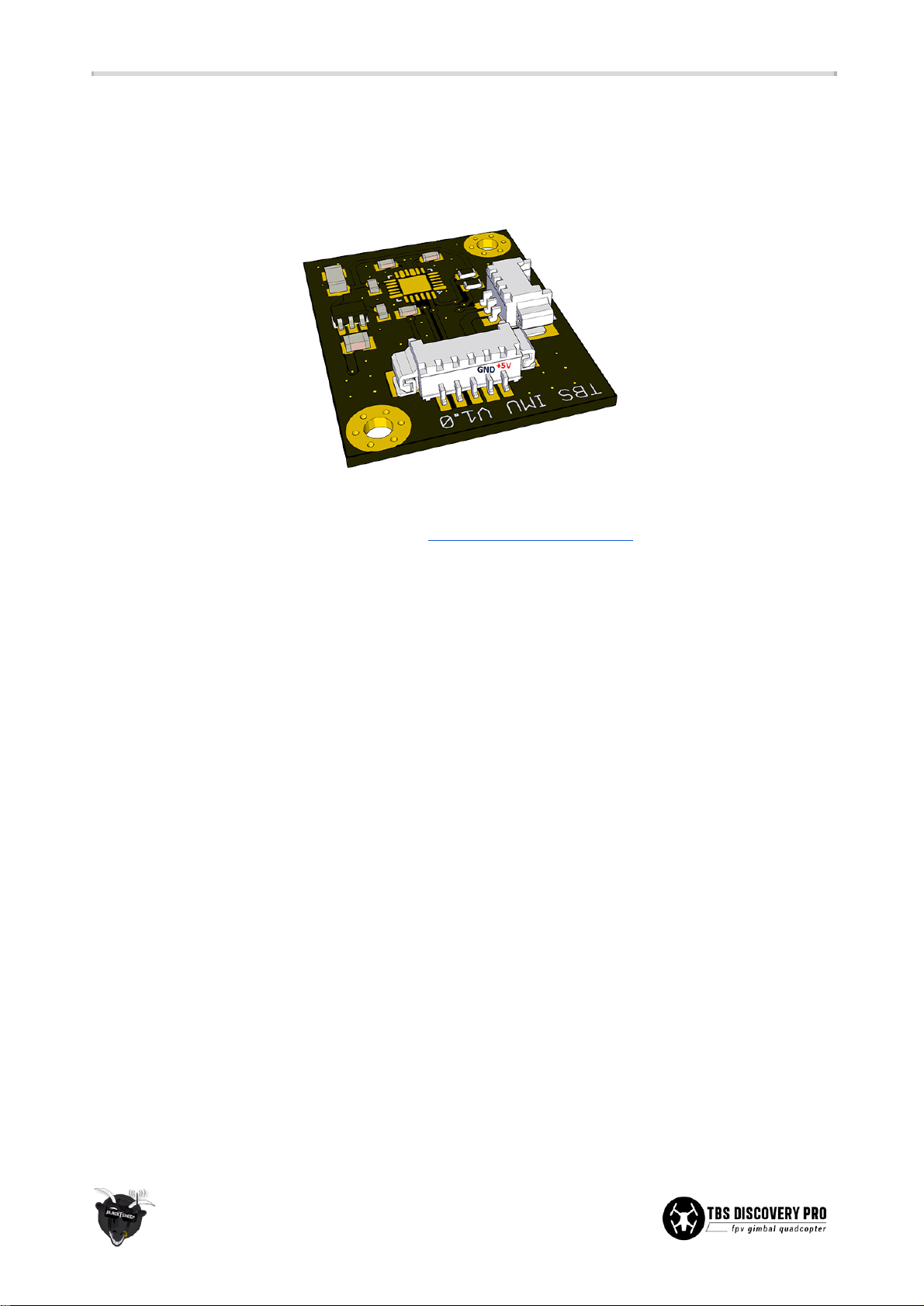
● Issue: Gimbal controller displays a blue light and motors not engaging
Solution: Try to connect your PRO to the SimpleBGC UI software and check what message you get
there. There is possibly a bad connection between the top plate and the gimbal IMU. Check the
connection by verifying the voltage at the IMU when everything is plugged in:
● Issue: The gimbal drifts or doesn't center properly
Solution: Install the SimpleBGC Software (www.basecamelectronics.com), level the gimbal on a heavy
and sturdy table and fix it using a thin book or similar. Turn off any UHF transmitters and disconnect
any video transmission devices. Ensure there are no vibrations on the table. Remove the camera and
strap from the Gimbal, as it simplifies levelling the gimbal. Connect the battery. The gimbal will try to
"fight" - do not worry about this it will not overheat the motors unless being kept running for
extended periods of time. Connect the micro USB to the top plate, and select "Connect" in the
software. Now select "Acc. Calibration" and wait for the motors to regain power. Then select "Gyro
calibration". If these steps have been done correctly, the gimbal will now lock dead center. You can
remove whatever you used to support the Gimbal and it will hold its position.
● Issue: The gimbal stutters or moves in jerky motion
Solution 1: Has the USB port been plugged in while the battery was disconnected? Unplug the USB,
then plug in the battery, and subsequently connect the USB plug again.
Solution 2: The IMU may be under tension, which prevents the gimbal from rotating freely. Loosen
the zip-ties of the IMU cable and give them some “play”, especially around the ball-bearing area.
● Issue: Video signal resets every few seconds
Solution: Too much current is being drawn from the CORE causing it to go into shutdown mode. The
video transmitter should be powered from a separate power source. Use a 5V or 12V BEC and
connect it to the + and - pads on the bottom plate.
50
Page 59
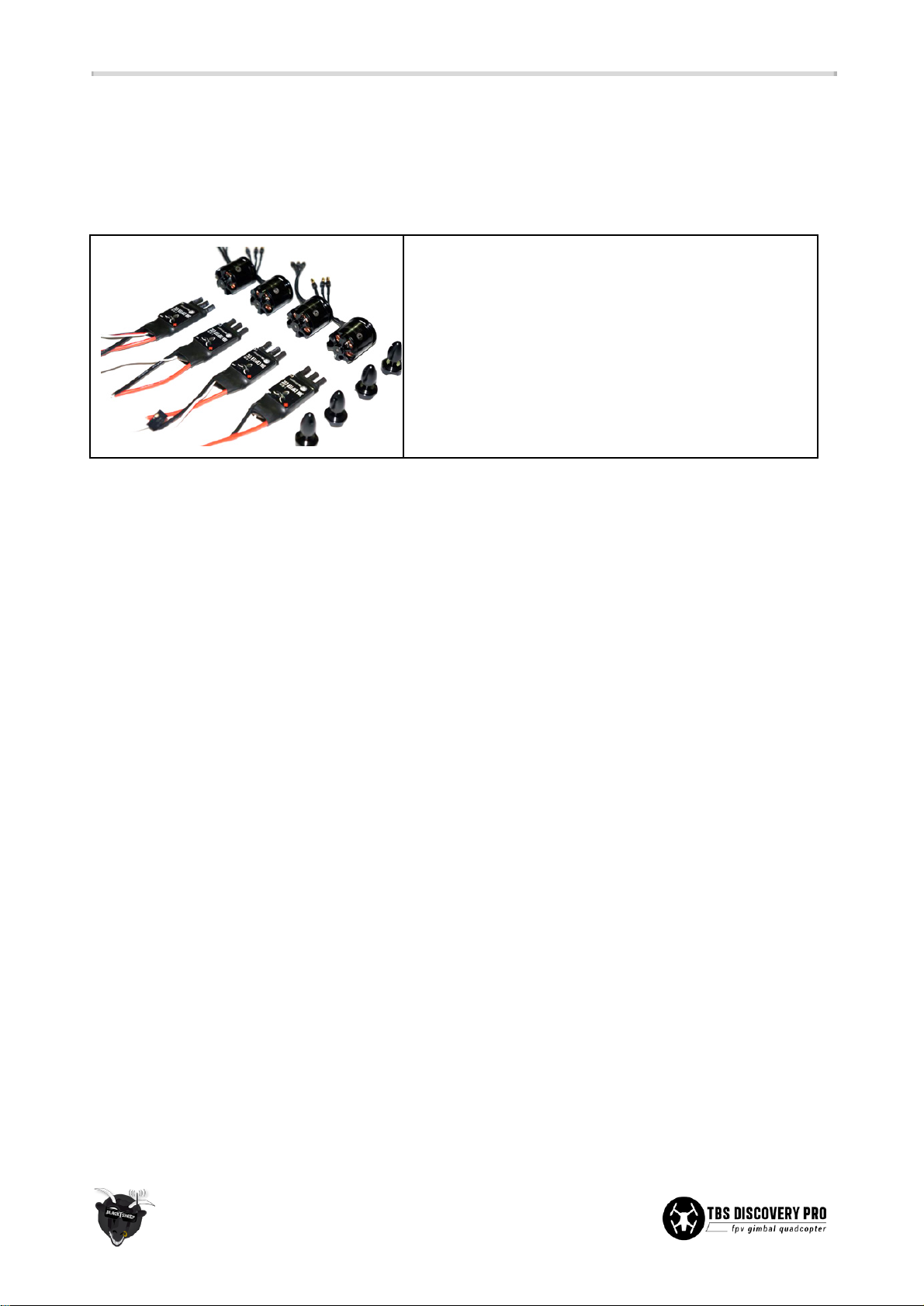
Recommended parts
Below is a list of compatible R/C and FPV gear for the TBS DISCOVERY PRO quadrotor. This will hopefully
make it easier to pick up spare parts and upgrades.
Power sets
TBS 900kV2 Motor / ESC Combo
For the more sophisticated, agile-flight loving pilot or for
those requiring super-vibration-resistant and high quality
motors.
● 4x TBS BULLETPROOF 30A ESC (flashed with
SimonK Firmware)
● 4x TBS 900kV2 Motor with M5 prop mount hubs
Individual parts
Motors
● TBS 900KV2 or Tiger Motors MT2216-10/11 900KV brushless motor (5mm shaft)
● DJI 2212 920KV brushless motor (8mm shaft)
● Sunnysky 2216-12 800KV brushless motor
Speed controllers
● TBS 30A Multicopter SimonK firmware speed controller
● DJI OPTO 30A no-BEC speed controller
● Tiger Motors 18A BEC speed controller
● HobbyKing F-20A or F-30A BEC programmable ESC with SimonK firmware
Flight controller
● DJI NAZA-M V1/V2/Lite with optional GPS
● OpenPilot CopterControl 3D
● APM2 Arduino-based autopilot controller
R/C Transmitter/Receiver
● Futaba 8FG / 7C with included receiver R6208SB / R617FS
● Graupner MX-12 radio with included GR-6 receiver
● ImmersionRC EzUHF 8ch Diversity receiver
● ImmersionRC EzUHF 8ch Lite receiver
51
Page 60

Propellers
● Graupner E-Prop 9x5-inch propellers
● Graupner E-Prop 10x5-inch propellers
● GemFan E-Propeller 10x5 Carbon Fiber propellers
● RCTimer Carbon Fiber 9x5-inch propellers
● RCTimer Carbon Fiber 10x5-inch propellers
Battery
● TBS 4S 3300mAh 30C or KyPOM KT4500/35-4S Lipo pack
● TBS 4S 4500mAh 30C or KyPOM KT3300/35-4S Lipo pack
● Gens Ace 4S 3300mAh 25C Lipo pack
● Zippy Compact 4S 4000mAh 25C Lipo pack
● Zippy Compact 4S 5000mAh 25C Lipo Pack
● Turnigy nano-tech 4S 3300mAh 35C Lipo pack
FPV transmitter
● Lawmate TM-240500-LM 2.4GHz 500mW transmitter
● TBS ROOKIE 5.8GHz 200mW transmitter
● TBS GREENHORN 5.8GHz 25mW transmitter
● BosCam TS-353 5.8GHz 400mW transmitter
FPV camera
● TBS69 or TBS59 FPV camera
● TBS ChipChip FPV camera
● Security Camera 2000 PZ0420 or CMQ1993X (IR blocked) 600TVL camera
52
Page 61

Spare parts
You can either get spare parts directly from us (team-blacksheep.com) or from one of our distributors and
retailers near you.
Our ever-growing list of retailers is published on the left at team-blacksheep.com/shop.
53
Page 62

Appendix
● Frame assembly diagram
● Gimbal assembly diagram
● Electronics installation diagram
● Common R/C receiver setups
● Video transmitter installation diagram
● CORE menu layout
● Center of Gravity diagram
Manual written and designed by ivc.no in cooperation with TBS.
54
 Loading...