

Page 1
1
Quick-Start Guide - TBS CROSSFIRE Micro TX Revision 2017-08-23
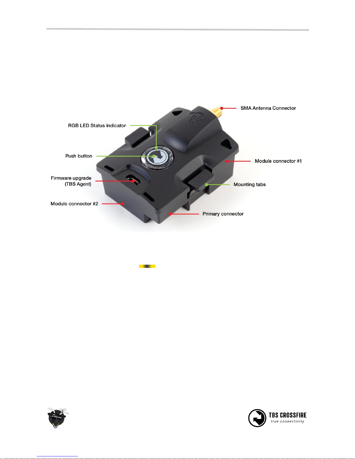
The CROSSFIRE Micro TX has a standard JR-form factor and works with any radio that supports PPM-
stream and/or TBS CRSF-format output. Transmitter power is selectable between 25mW and 100mW, and
TX status is shown using a RGB LED lite behind the push button. Frequency band 868 MHz and 915 MHz
are supported.
Push button functionality
If there is no link (LED pulsing orange ):
• Long press: Toggle frequency between 868 MHz and 915 MHz. Once changed it will blink white 1x
for 868 MHz and 2x for 915 MHz.
• Short press: Enter bind-mode (LED blinking green ▀ ▀ ▀ ).
If the receivers needs to be updated it will start blinking blue (■ ■ ■ ■ ). Press the button again
to confirm. The update will start and the LED will be solid blue (▀ ▀ ▀ ) until the update is
complete. Once update is complete the LED will turn solid green (▀▀▀) or orange (▀ ▀ ▀ ).
If there is a link (LED solid green ▀▀▀ or orange ▀ ▀ ▀ ):
• Long press: Set failsafe
Configuration of the internal settings (region, output power, dynamic power, and operation mode) and
receiver configuration (output mapping, channel mapping ect. ) is done via any remote supporting CRSF
(TBS TANGO, OpenTX ect.) remote. The TBS CROSSFIRE Micro RX V2 comes with CH1: PPM, CH2-CH4 PWM
default settings.
Page 2
2
Configuration
TBS TANGO remote
The easiest way to setup and configure the TBS CROSSFIRE Micro TX is via our TBS TANGO remote. Simply
plug in into the back of the remote and bring up the configuration menu by holding the rocker-scroller for
3 seconds, and go to the Device sub-menu.
The changes are stored internally on the transmitter module, so if you do not own a TANGO remote (or
OpenTX radio), you can borrow one for a minute to make the necessary changes and then pop it out.
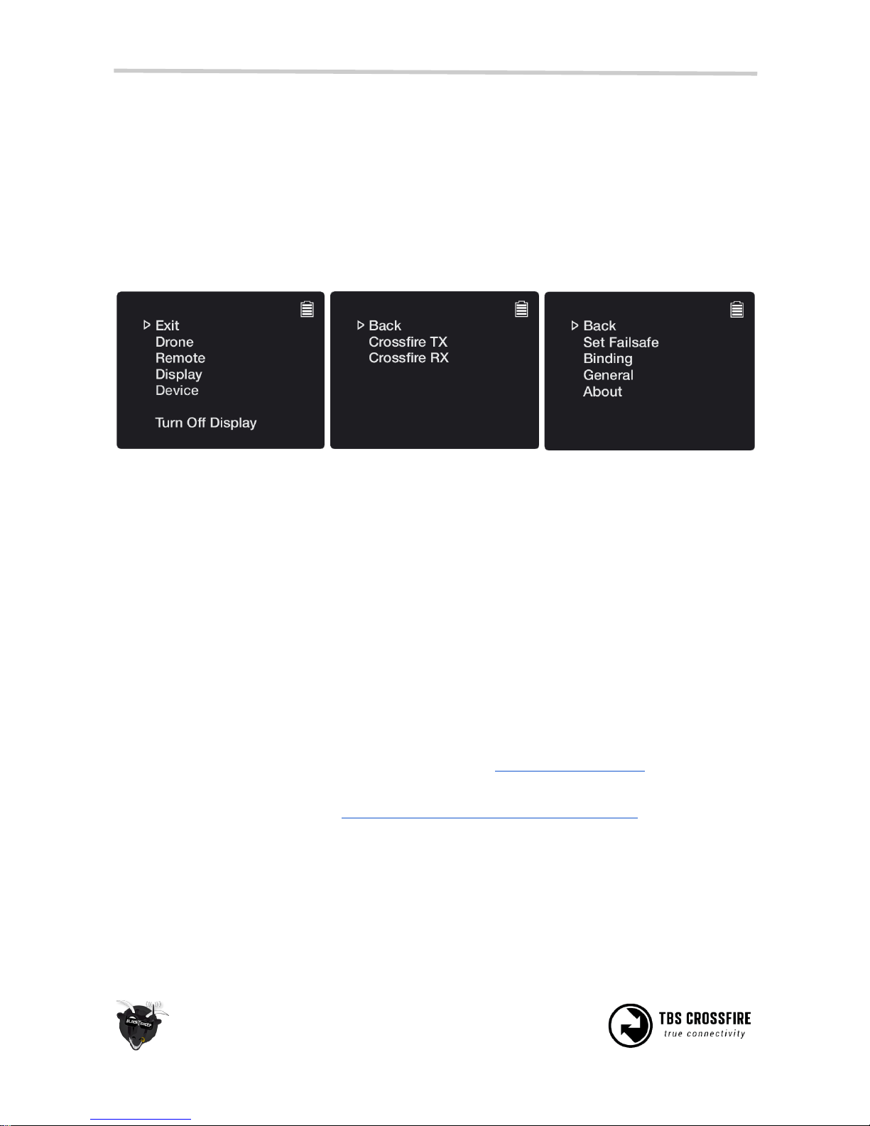
Enter the configuration menu by
Holding the jog-scroller for 3
seconds
Select Device and the detected
CROSSFIRE modules will be listed
(note the receiver is also present)
Pick the “Crossfire TX” module to
find a listing of all the available
modes and changeable settings
This method is also available on the standard transmitter module.
OpenTX and LUA scripts
The CROSSFIRE allows bidirectional communication, that means the radio display interface (currently only
OpenTX radios supported) can used to remotely configure any TBS device (currently CROSSFIRE, CORE
PRO) over the BST connection.
The following requirements must be fulfilled to be able to use this feature:
• Any OpenTX radio (any Taranis, Horus) with OpenTX 2.2.x or higher
○ Nightly builds provided in the “News” section at http://www.open-tx.org/
• TBS CROSSFIRE LUA script package on root of SD card
○ Currently provided at http://downloads.open-tx.org/2.2/nightly/sdcard/
• TBS CROSSFIRE TX/RX V1.62 or higher
• TBS CORE PRO/FPVision V1.70 or higher
• TBS CORE PRO with SmartAudio (purchased after 07/2015) - for UNIFY PRO control
Page 3
3
Connect the devices as normal via BST cables and make sure the CROSSFIRE radio link is up and running.
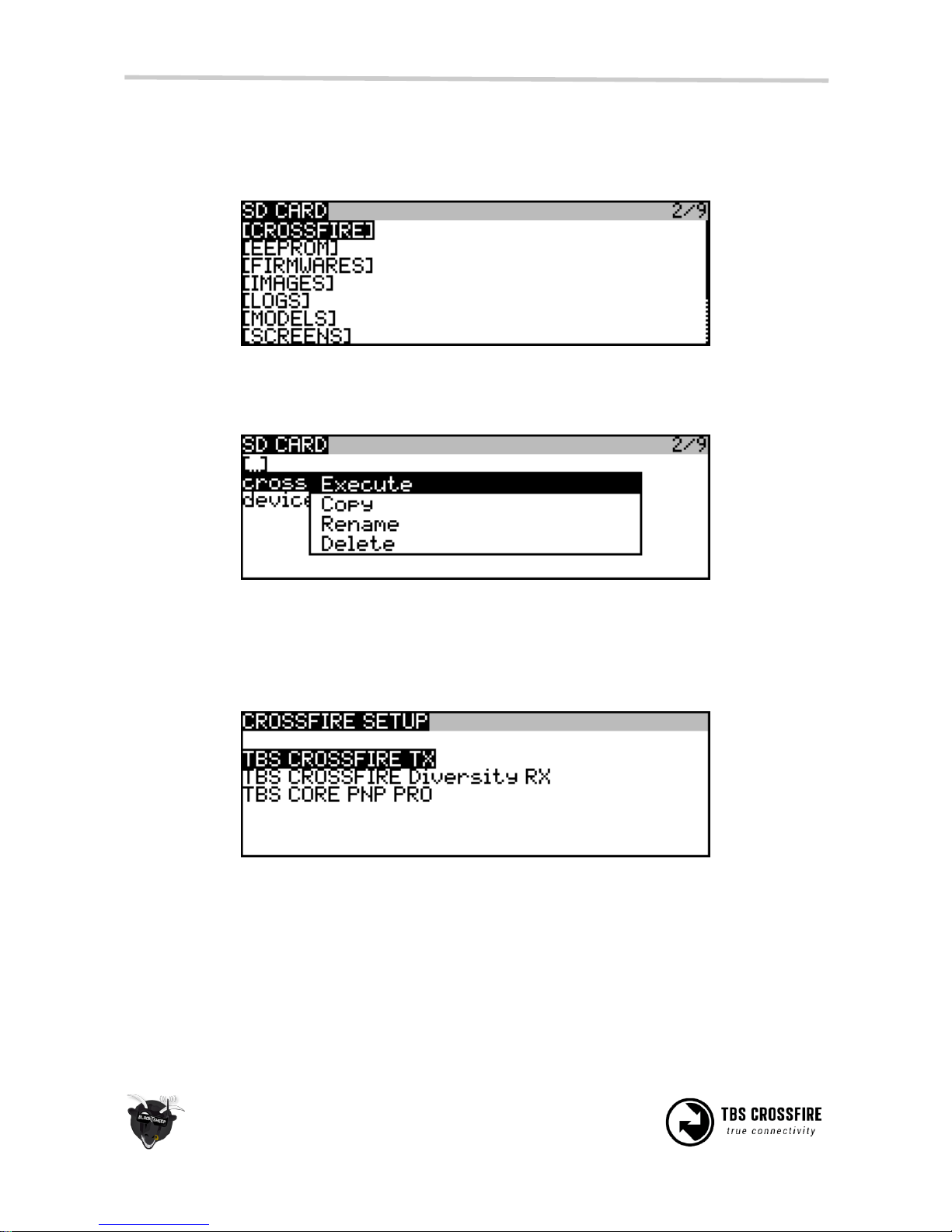
On the radio, press and hold the “Menu” button to bring up the “Radio setup”. Press “Page” to go to page 2
“SD Card”.
Move to the “CROSSFIRE” directory and open it. Press and hold “Enter” on the “crossfire.lua” file, select
“Execute” to open the script. The device.lua file is not meant to be executed.
All the supported TBS devices that is connected via BST to the CROSSFIRE RX will show up immediately, e.g.
“TBS CROSSFIRE TX”, “TBS CROSSFIRE Diversity RX” or “TBS CORE PRO”. Pick either to change the settings.
Note: the CORE PRO will not show up of the standard POWERCUBE is connected, disconnect it first from
BST.
The changes will be committed once you leave the settings page.
Page 4
4
Output SBUS, CRSF or PPM on receiver
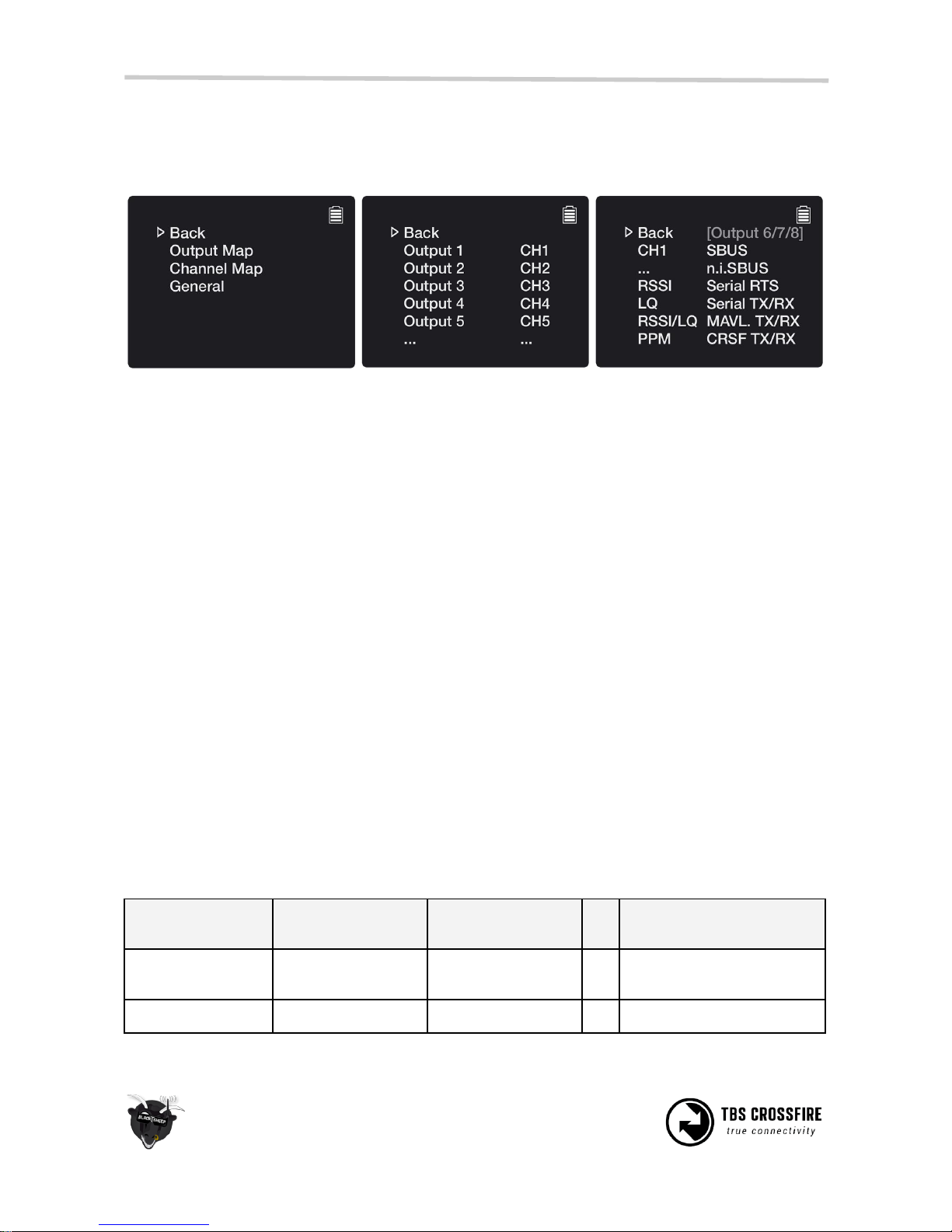
By selecting the “Crossfire RX” / “TBS CROSSFIRE RX” or “TBS CROSSFIRE Diversity RX” in the configuration
menu, you can change the output mapping, including the signal format on each pin (SBUS, CRSF, PPM).
Enter the configuration menu and
under “Crossfire RX”, pick “Output
Map”
This lays out all the physical pins
and their source signal format.
Pick a output to change. PPM can
be selected in all channels, while
SBUS, CRSF and Serial is restricted
to output 6, 7 and 8.
Difference between SBUS and CRSF
SBUS is a high frequency one way communication protocol, up to 150 updates per second (Hz). While our
TBS CRSF (CROSSFIRE) is a two-way, low-latency, error detection, communication protocol which allows
uplink- and model-telemetry (via BST to RX) to be carried back to the remote control.
At the moment the CRSF protocol is supported by the following flight controllers (FC):
• KISS
• Betaflight
• Raceflight
• iNav
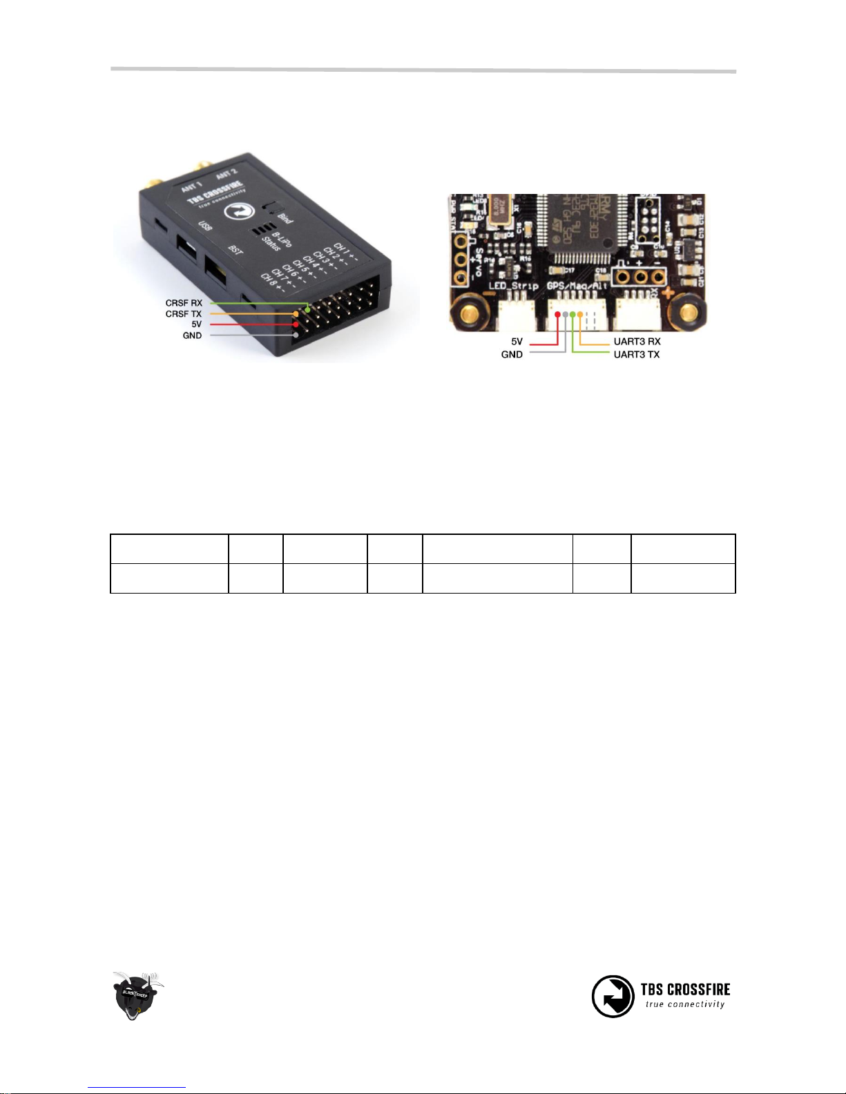
Wiring CRSF to flight controller
Since the CRSF protocol is serial, it has to be connected to a free serial/UART port on a supported flight
controller. On the COLIBRI RACE it must be UART3. If you use the POWERCUBE with FPVision, you can use
also use UART2. The pin-out and wiring layout is shown in the following table.
CROSSFIRE MICRO
V1 RX
CROSSFIRE MICRO
V2 RX
CROSSFIRE
DIVERSITY RX
Clean-/BetaFlight Serial
port (COLIBRI or other)
Ch./Pin 1 TX
Ch./Pin 1 TX, 5V,
GND
Ch./Pin 8 TX, 5V,
GND
⇒
UART2 or 3 RX, 5V, GND
Not available
Ch./Pin 2 RX only
Ch./Pin 7 RX only
⇐
UART2 or 3 TX
Page 5
5
Make sure you also configure the “Output Map” on the receiver to output CRSF RX on output 7 and CRSF TX
on output 8.
Diversity RX
COLIBRI FC
To use the CROSSFIRE Micro Receiver V2, you have to use the expander board to easily get to the pins for
channel 1 and 2 required for CRSF communication.
In addition to the CRSF serial connection, you might want to connect BST (BlackSheep Telemetry) between
the CROSSFIRE RX and COLIBRI to provide extra telemetry and make changes remotely on the CORE PRO
(if connected) or FPVision (if part of the POWERCUBE).
CROSSFIRE RX
BST ⇒
CORE PRO
BST ⇒
POWERCUBE standard
INT. ⇾
COLIBRI FC
CROSSFIRE RX
BST ⇒
BST ⇒
POWERCUBE FPVision
INT. ⇾
COLIBRI FC
Manual written and designed by ivc.no in cooperation with TBS.
 Loading...