

Page 1
1
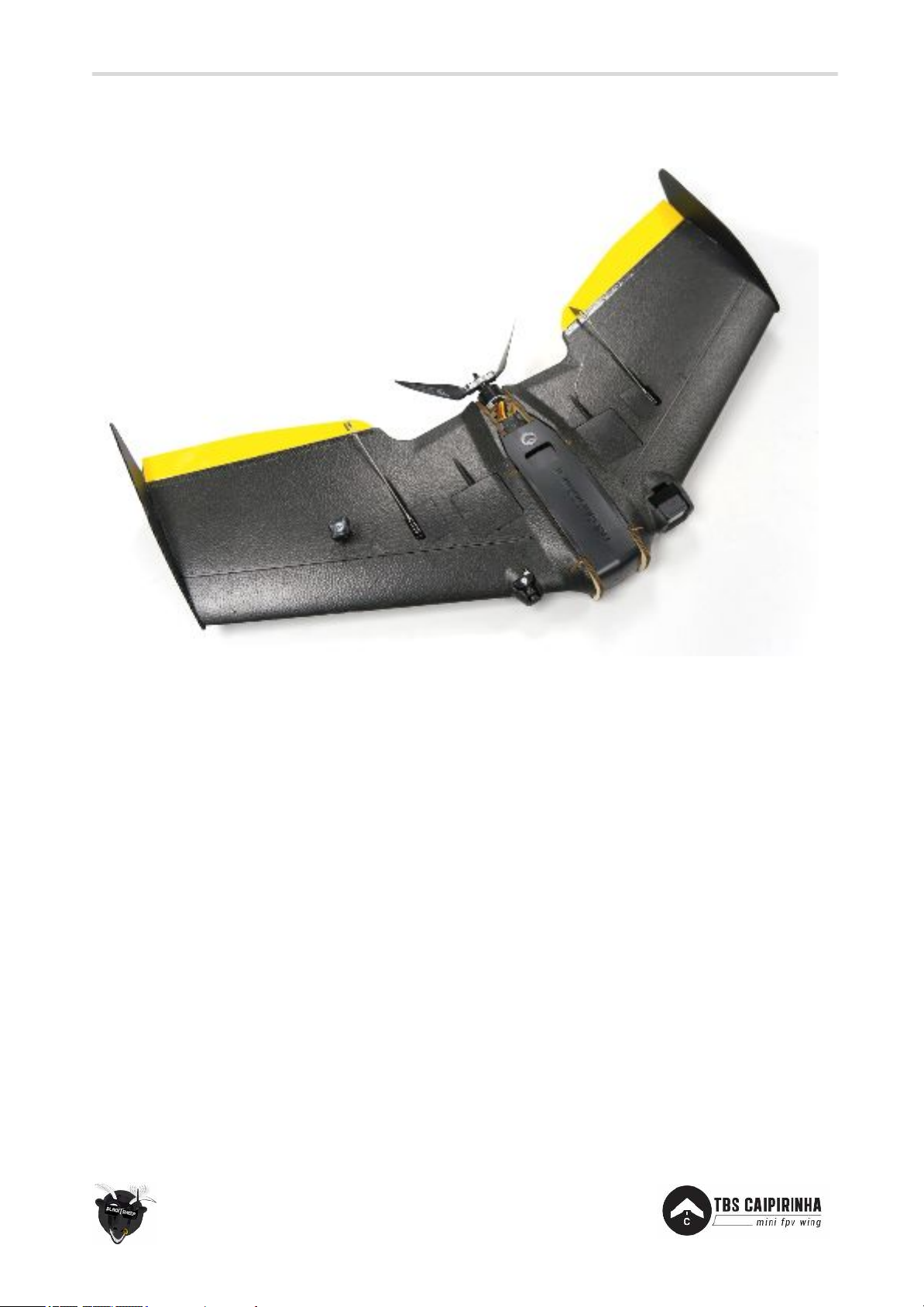
TBS CAIPIRINHA II Mini FPV Wing
Small, integrated, fly anywhere plane
Revision 2018-01-18
The TBS CAIPIRINHA II is a gentle long range cruiser that turns into a fierce mountain diver with just a
slight push on your pitch stick.
The wing is based on the Wipeout by HappyFlyers from Switzerland! A polycarbonate battery bay top,
push-to-open equipment bays, a PDB with up to 3 battery inputs, wiring channels that stretch across the
entire wing, a huge 6mm-plywood-lined center section are just some of the innovations that make this
plane stand out from the rest. An ultra-sleek and aerodynamic finish ensure that no energy goes to waste,
and a very good glide slope makes thermalling or long distance sloping highly enjoyable.
We can confidently say it is going to be the only long range cruiser you will ever need, and the only flying
wing in its weight class with such a performance envelope.
Features
● Small, lightweight, fly anywhere design
● Ultimate in flight stability and endurance
● Virtually indestructible EPP/Plywood construction
● Pre-cut camera, servo, battery, R/C receiver and video transmitter slots
● 2x push-to-open equipment bays for R/C and FPV electronics
● Pre-cut, sanded and covered ultra-lightweight elevons & pushrods
Page 2

2
Before we begin
Thank you for buying a TBS product! The TBS CAIPIRINHA II is a new FPV wing from Team BlackSheep (TBS)
and features the best design practices available on the market to date, providing great flying duration and
incredible FPV characteristics.
Please read this manual carefully before assembling and flying your new TBS CAIPIRINHA. Keep this
manual for future reference regarding tuning and maintenance.
Our request to you
The aircraft may not be used to infringe on people's right to privacy. We have designed a toy with mind
blowing capabilities. It is your responsibility to use it reasonably and according to your experience level.
Use common sense. Fly safe. You are on your own. TBS has no liability for use of this aircraft.
● Locate an appropriate flying location
● Obtain the assistance of an experienced pilot
● Practice safe and responsible operation
● Always be aware of the rotating propeller
● Prevent moisture
● Keep away from heat or excessive amounts of sunlight
Page 3
Type:
Powered medium sized flying wing
Airframe:
Black molded EPP (Expanded Polypropylene) foam material
Wingspan:
36.5 inch / 930mm
Winglets:
Symmetrical, 3mm corrugated lightweight board
Battery:
4500mAh 4S, to 6600mAh 4S, 20C or higher
Battery size:
Suggested dimension W48 x H36 x L150 mm, 525g
Max. dimension W60 x H44 x L165 mm, 550g
Motor:
2200-class, 1000-1200kV
Speed controller:
40 to 60A ESC
Receiver:
3 channels or more
Propeller:
10x6in folding prop - recommended for 4S setup
Servos:
2x park type digital servos, high torque (4-6kgf), metal gears, 35cm cables
Center of gravity:
Across the bumps near the wing spars and middle of wing
Pilot camera
Small 26x26x30mm FPV camera
HD camera:
GoPro Hero Session (any model)
Speed range:
40 to 100km/h
Duration:
90min flying time (TBS equipment, max efficiency flight)
Endurance:
45miles / 75km
All-up-weight:
50oz / 1400g AUW (including GoPro Session5 and battery)
3
Specifications
Required tools
● Utility knife
● Storage tape (for hinges)
● Glue (Foam-safe CA, Gorilla, UHU-POR are compatible)
Page 4
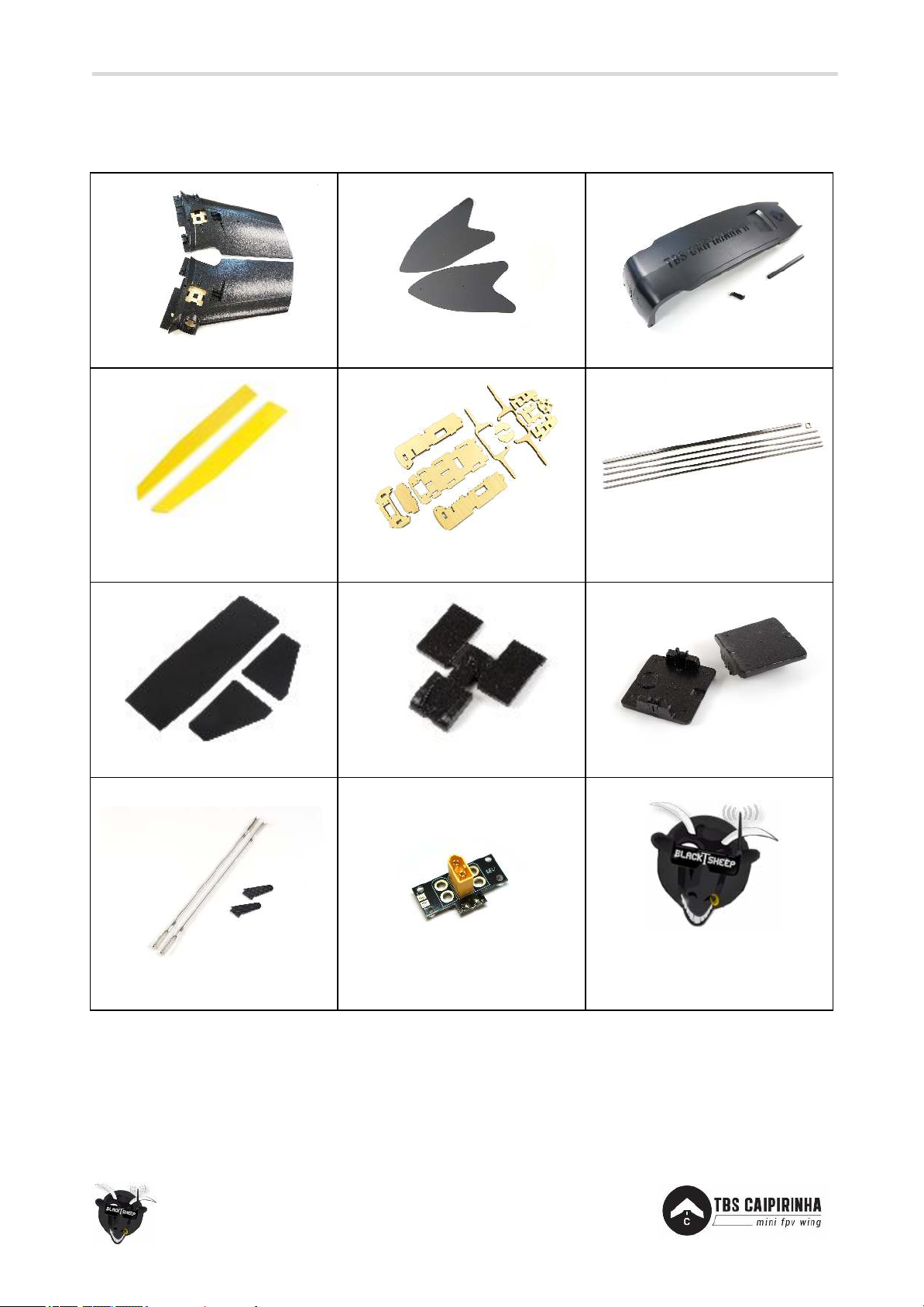
2x Wing halves and covers
2x Symmetrical winglets
1x Plastic cover and screws
2x Plywood lightweight elevons
(pre-installed on PNP kit)
1x Plywood battery bay and
motor mount
5x Glass fiber spars and ribbon
1x Set of adhesive covers
1x Piece of cover foam
1x Push-to-open foam covers
2x Ø1.0mm control links and
horns (pre-installed on PNP kit)
1x Power distribution board
1x Teaspoon of awesomeness
(rarely visible but always included)
4
Part list
Before building your TBS CAIPIRINHA II make sure the following items are included in your kit.
Page 5
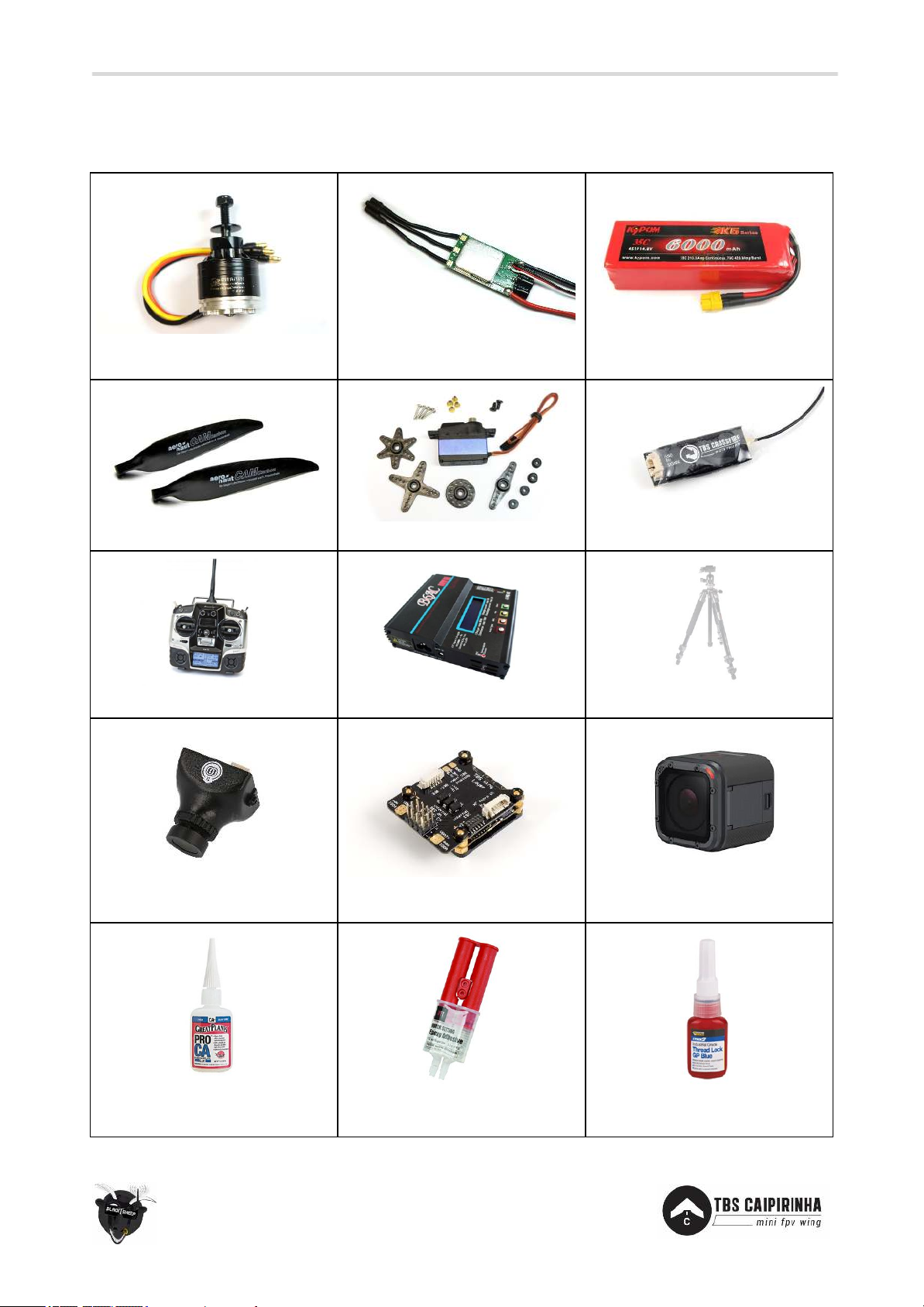
1x 1000-1200kV 2200-class
brushless motor
1x 50A Speed controller
1x 4S 4500mAh 20C to 4S
6600mAh 20C XT60 LiPo pack
1x 10x6-inch folding propeller
2x Digital servos with servo arm
1x R/C receiver 3-ch or more
1x R/C transmitter 4-ch or more
1x LiPo 4S charger
1x Headset or ground station
1x Pilot camera (26x26mm)
1x Wing layer and FPVision, or
other VTX, PSU and OSD
1x GoPro Hero Session HD
camera
1x Thick CA glue and kicker
(accelerator) and PVA glue
1x Two part epoxy adhesive or
hot glue
1x Medium thread-lock
(purple/blue)
5
Required parts
To get in the air the following equipment and parts are needed for assembly.
Page 6
R/C transmitter/receiver:
TBS TANGO FPV remote controller with TBS CROSSFIRE Micro V2 RX
or FrSky Taranis X9D radio with TBS CROSSFIRE Micro TX / Micro V2 RX
or Graupner MX-12 2.4GHz radio with bundled receiver (GR-6)
Wing electronics:
HobbyWing 50A Skywalker Wing ESC
Graupner Digital Servos 6kgf/cm, 5-6V (2x)
CP2814-1050kV Cobra Motor
Aeronaut 10x6 folding prop with prop assembly (CNC aluminum)
System power:
TBS FPVision (includes PNP PRO DCDC V2)
Battery:
4S (14.8V) 4500mAh 20C to 4S (14.8V) 6600mAh 20C Lipo pack
Battery charger:
TBS CHARGER (50W)
FPV transmitter:
TBS FPVision (includes 5G8 video transmitter) with TBS Triumph-Stub
SMA RHCP 5.8GHz antenna
FPV receiver:
FATSHARK DOMINATOR 5.8GHz regular module
or LaForge V4 Diversity Rx
FPV pilot camera:
TBS ZEROZERO V2 FPV camera
FPV goggles:
FATSHARK DOMINATOR HD V3
HD camera:
GoPro HERO Session (any model)
Ground station accessories:
FPV goggles
6
Choosing the right setup
If you are just getting into the hobby and you have absolutely nothing, consider the following components
to buy. Use these suggested setups as a “shopping list” if you are just getting started. Any existing gear you
already own (e.g. remote controls, chargers, batteries) can be used with the TBS CAIPIRINHA II.
These setups, with the exception of the camera tripod, are available from Team BlackSheep. Remote
controls can be purchased at your local hobby shop, camera tripods are available from big electronics
wholesalers or Ebay.
TBS CAIPIRINHA setup for short range flights
● Expected flight time: 40-60 min
● Approximate cost: US$ 1,350 - US$ 1,550
● Experience level: Beginner to Expert
● Ideal for: Parks, R/C clubs, front lawns
Page 7
R/C transmitter/receiver:
TBS Tango
or FrSky Taranis X9D with
TBS CROSSFIRE TX and 8ch Diversity Rx
Wing electronics:
HobbyWing 50A Skywalker Wing ESC
Graupner Digital Servos 6kgf/cm, 5-6V (2x)
CP2814-1050kV Cobra Motor
Aeronaut 10x6 folding prop with prop assembly (CNC aluminum)
System power:
TBS CORE PRO with 100A digital current sensor
Battery:
4S (14.8V) 4500mAh 20C to 4S (14.8V) 6600mAh 20C Lipo pack
Battery charger:
TBS Charger
FPV transmitter:
TBS UNIFY 5G8 PRO V3 or TBS UNIFY 2G4 500mW/800mW
FPV receiver:
LAFORGE FATSHARK MAIN MODULE V3 or TBS GROUNDSTATION 2G4
FPV pilot camera:
TBS ZEROZERO V2 or TBS69
FPV goggles:
FATSHARK DOMINATOR HD V3
HD camera:
GoPro HERO Session (any model)
Ground station accessories:
TBS 3S 5000mAh Ground Station Lipo
Camera Tripod to mount your gear (e.g. Cullmann Primax 150)
7
TBS CAIPIRINHA setup for long range flights
● Expected flight time: 40-60 min
● Cost range: US$ 1,700 - US$ 2,000
● Experience level: Expert
● Ideal for: Long, wide open fields, plains, coastlines and valleys or urban flying
Page 8
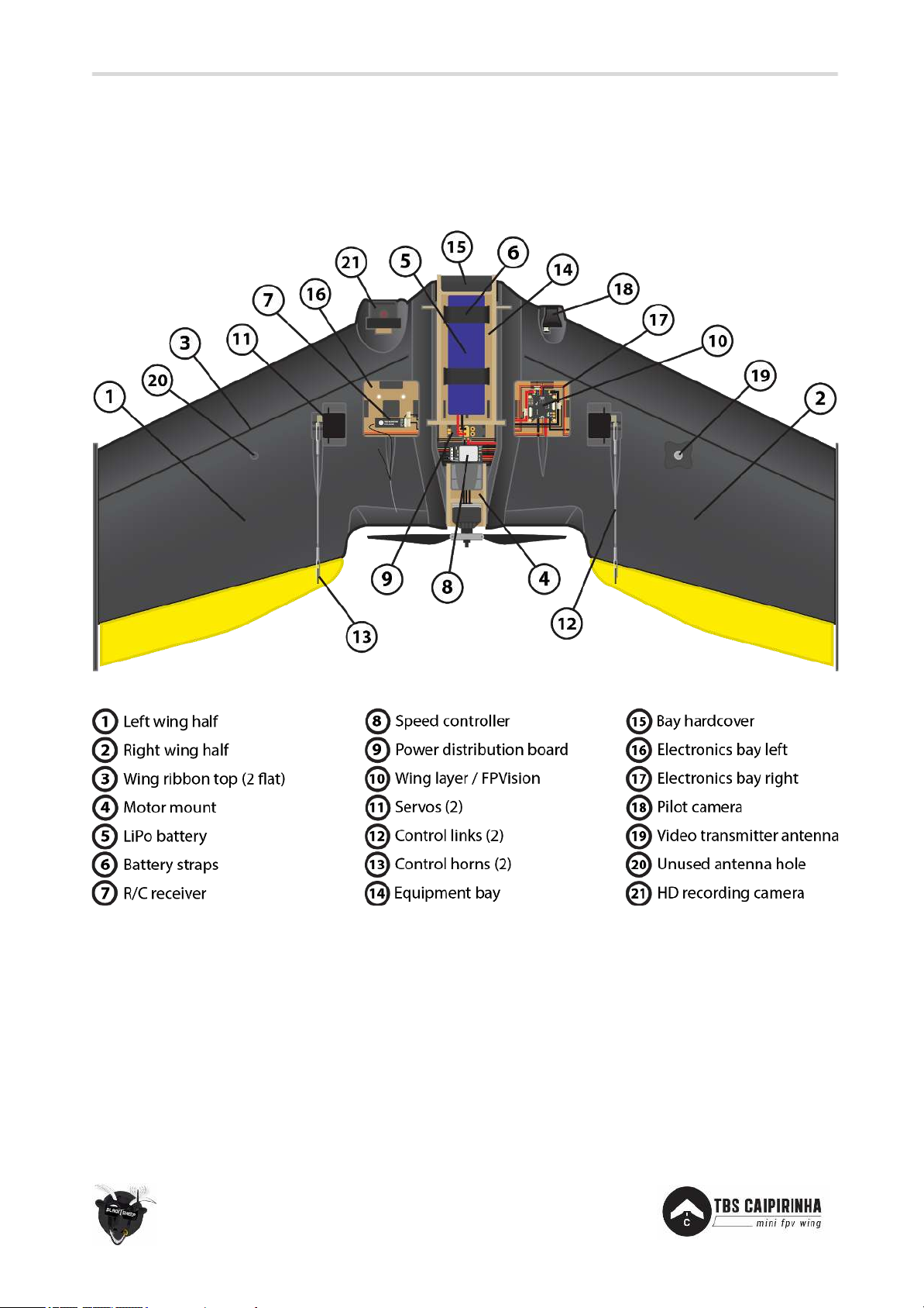
8
Wing assembly
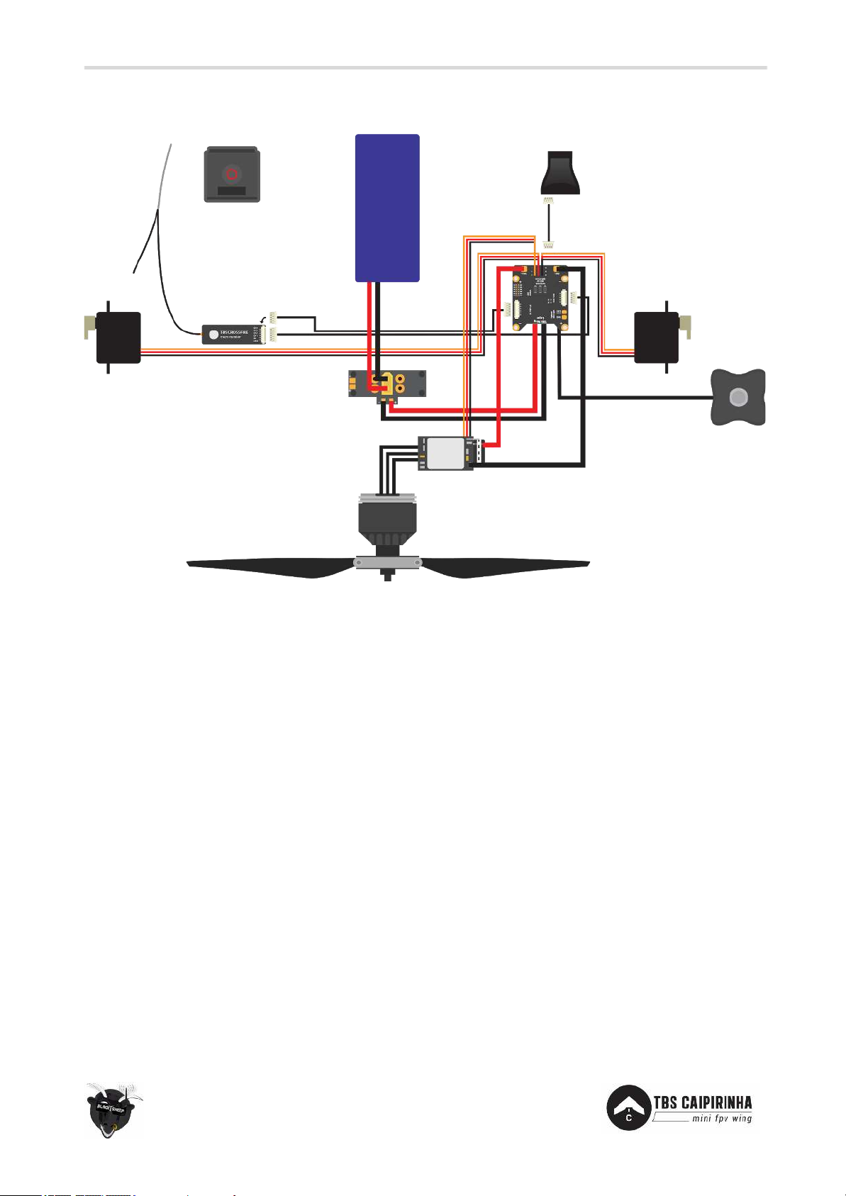
Top assembly overview of a common wing setup, including TBS Wing Layer, TBS FPVision, TBS Crossfire
Micro V2, TBS ZeroZero V2, Cobra 1050kV motor, HobbyWing 50A ESC, Aeronaut folding 10x6 propeller,
and GoPro Hero Session 5.
Page 9
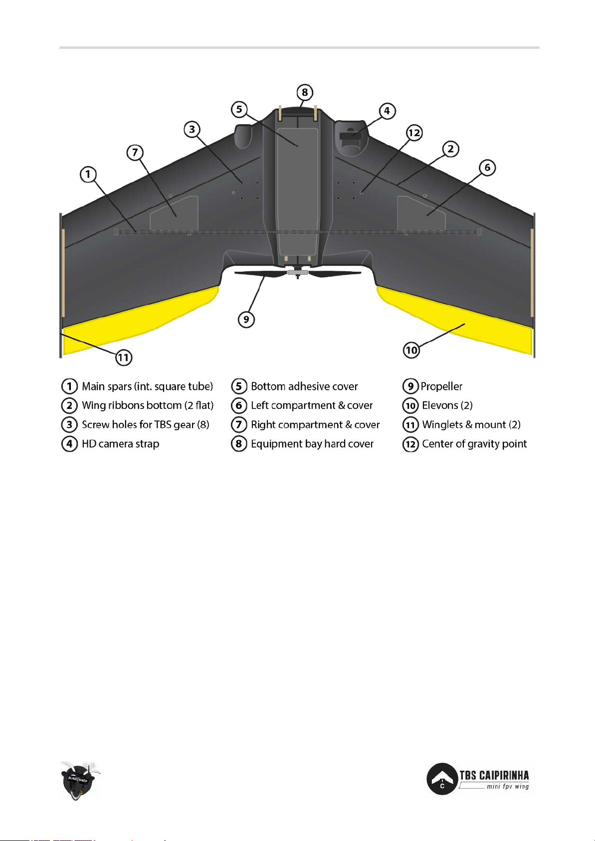
9
Underside of the wing assembly.
Page 10
10
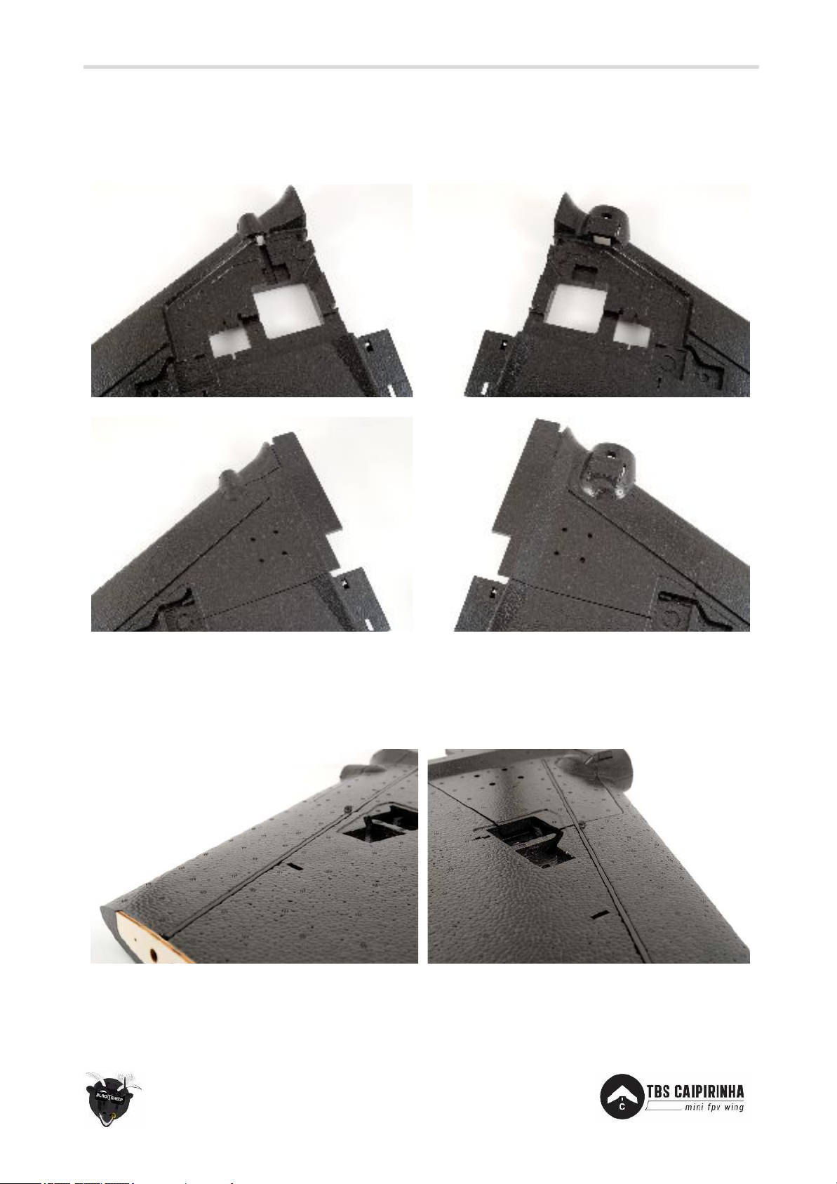
Attach underside covers
The wing halves come with underside covers that needs to be glued in place. These make up the internal
wiring channels. Any custom routing layout can be done at this point in the assembly.
Spars on wing
The wing spars add strength and rigidity. There are four spars, two on each wing. Glue these in place with
CA/superglue. Add a decent amount in the cavity and keep the spar in place until the glue has properly set.
Page 11
11
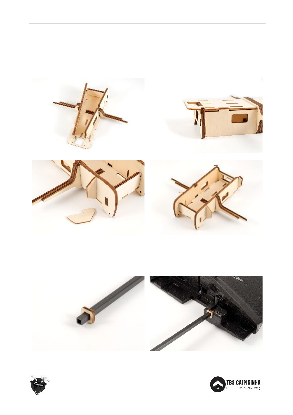
Battery bay
The battery is kept in the middle of the wing and can be used to adjust the center of gravity. A plywood and
support straps keeps the battery secure. Begin by assembling the plywood pieces. Follow the photos below
to complete the build, be careful not to overbend the pieces.
Main wing spar and wood bit
Glue the wood bit on the exact center point of the main wing spar and insert it into the corresponding tube
on the wing halves. This makes sure the tube is in the middle of the wing.
Page 12
12
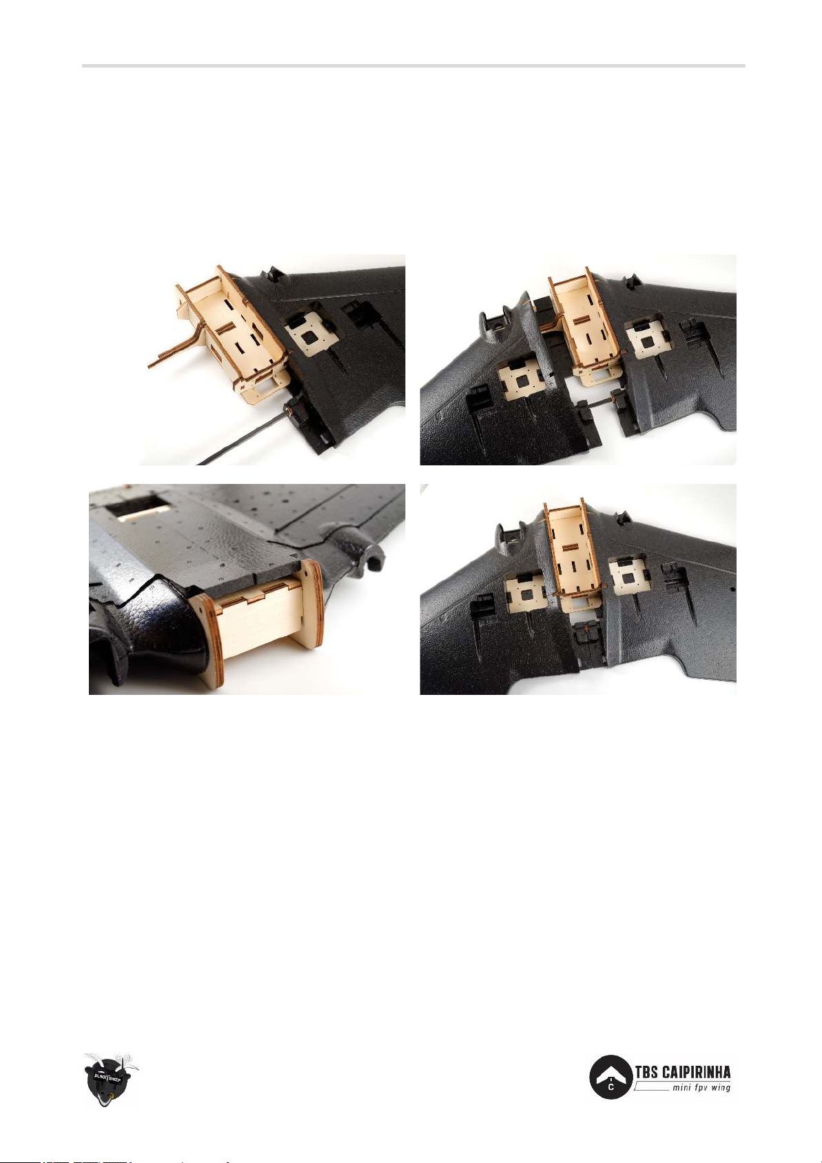
Wing halves assembly
Roughen the main spar with a sandpaper, apply glue to one side of the spar and insert the spar into the
side of the wing. Roughen and cover the surfaces of the battery bay, adjoining foam faces and the spar on
the opposing side with PU glue, spray water to activate the glue. Insert battery bay into one of the wing
halves, align the other wing half on the wing spar and push the two together to form a solid wing. Use tape
to keep the two halves pressed together.
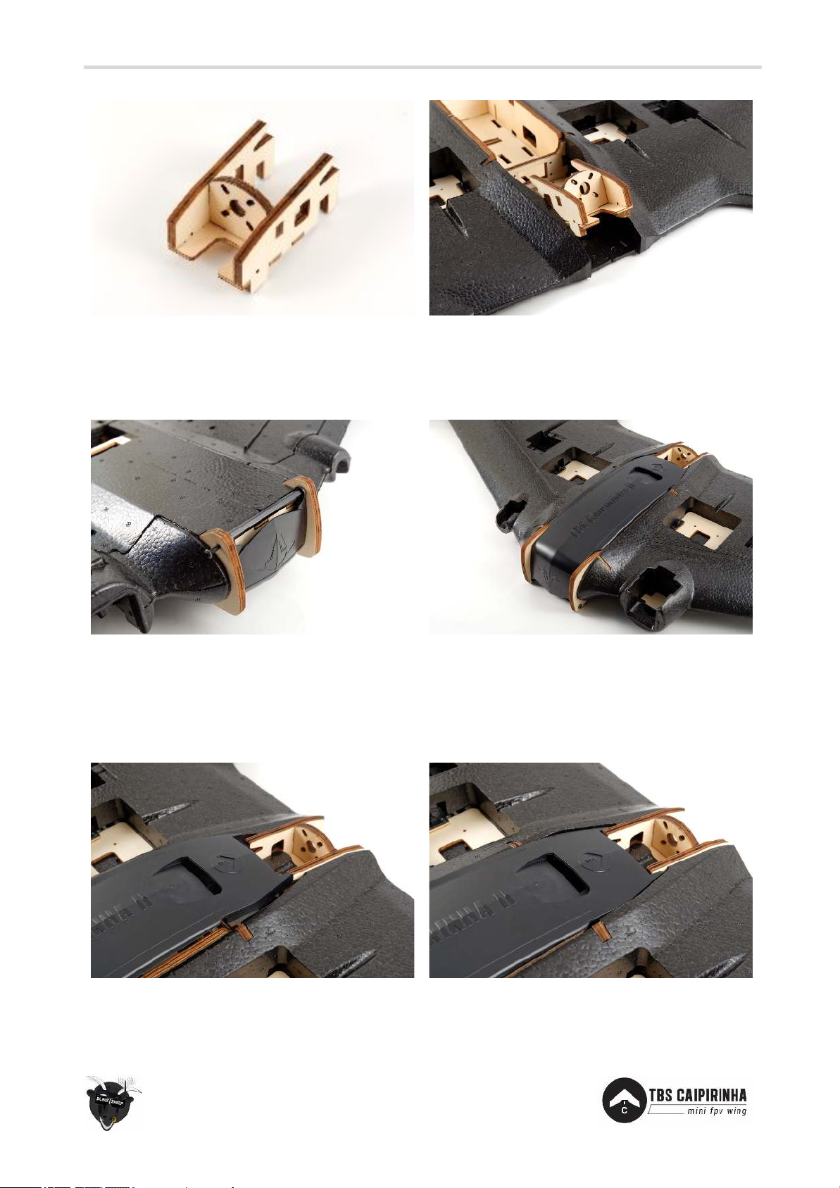
Motor mount
Assembly the four plywood pieces to form the motor mount assembly. Glue it in place at the rear end of
the wing, use CA or Epoxy. Make sure to add glue to all the sides that are exposed to the foam frame, as
this is a load-stressed area. It is possible to attach the motor after the motor mount has been installed.
Page 13
13
Hard top cover installation
Put the hard top cover on top of the battery bay and align the front screw holes with the corresponding
holes on the battery bay assembly. Add small drop of thread lock to the screws.
Opening and closing hardcover
The hard cover is properly held in place by the motor mount assembly. Opening the cover is done by
holding two fingers on either side of the went slot and one finger on the rear end. Push down on the end
while lifting up the middle section. Do the reverse to close the hard cover. The cover is meant to flex.
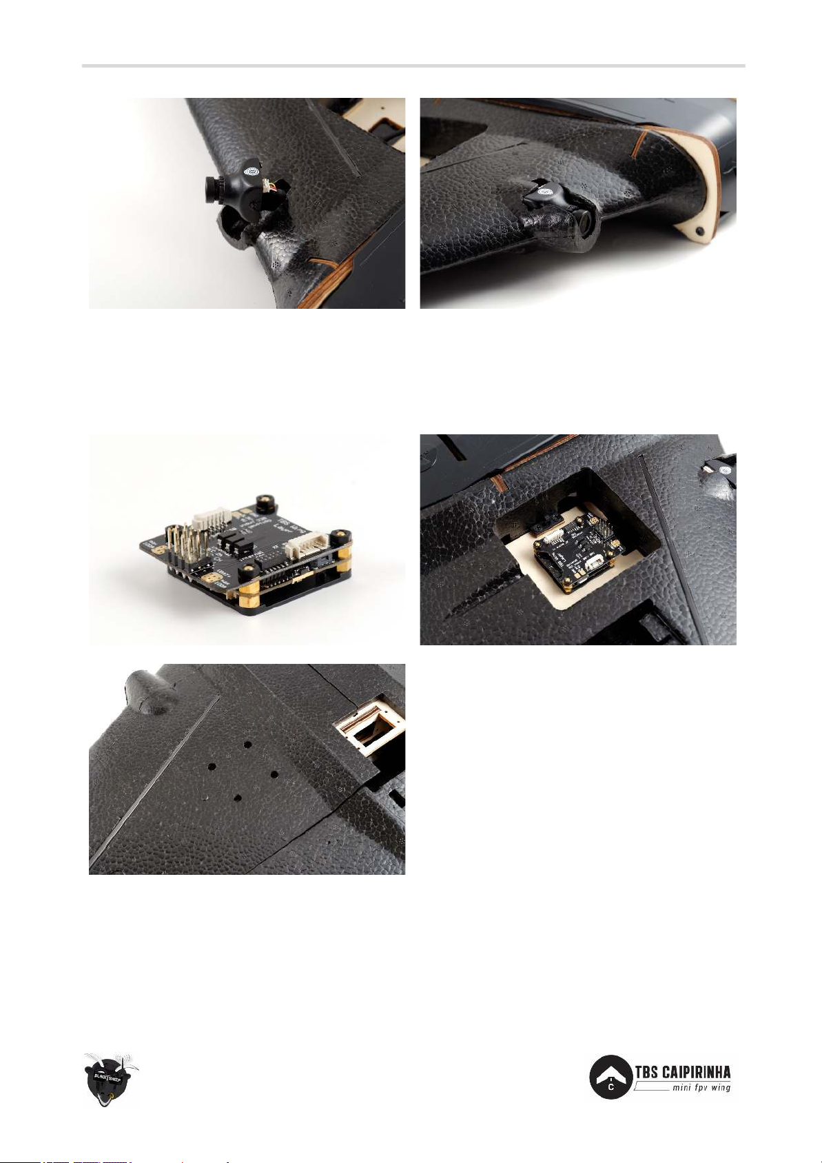
Pilot camera
The pre-cut camera slot fits standard 26x26mm units (e.g. TBS ZeroZero V2). Use hot glue to secure it.
Page 14
14
Install TBS gear
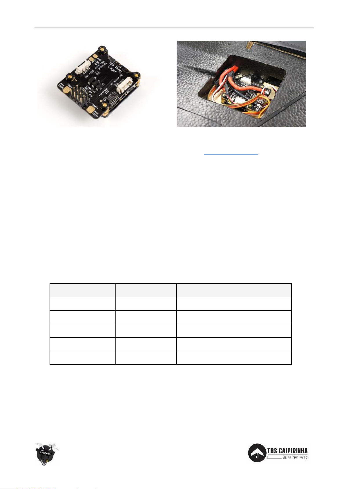
The electronics bays on the wings are made to accomodate the TBS FPVision and TBS Wing layer. Assembly
the stack and use the screw holes on the bottom to secure it to the wing. Look at the “Electronics
installation” section later in the manual for more specifics.
R/C receiver
The R/C receiver can be installed in either electronics compartment or transceiver bay on the underside of
the wing. For best performance it is recommended to keep it as far away from the video transmitter (VTX)
as possible. Use velcro-tape to secure it in the frame.
Page 15
15
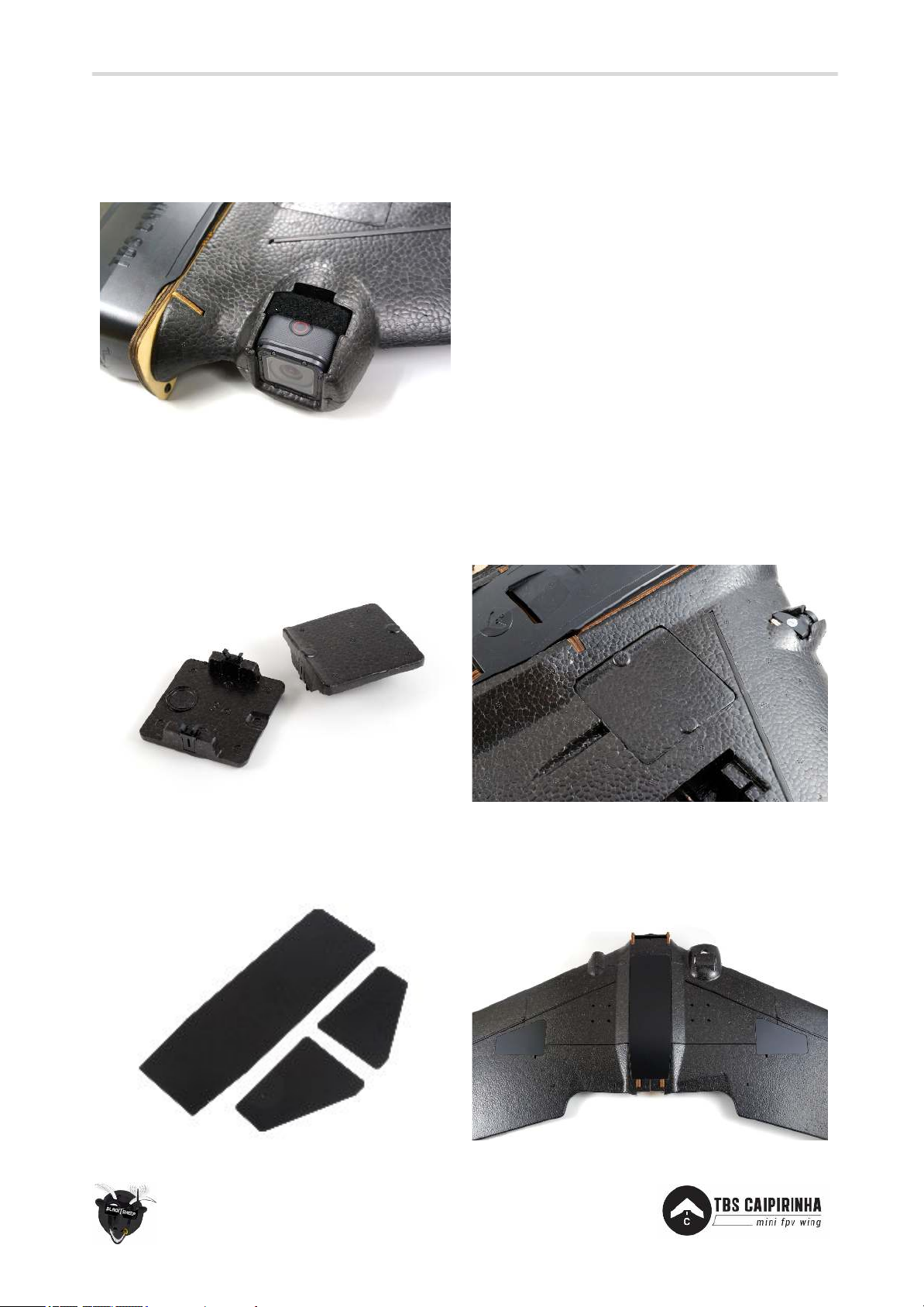
HD camera
A GoPro session camera can be installed in the designated slot in the front of the wing. A support strap is
used to keep the camera in place.
Push-to-open bays
To provide quick access to the electronics bay, the top bays have a retaining mechanism that can easily be
engaged by pushing on both sides of the bay.
Adhesive cover pads
Once the PDB and gear in the underside bays is installed, use the adhesive pads to cover them.
Page 16
16
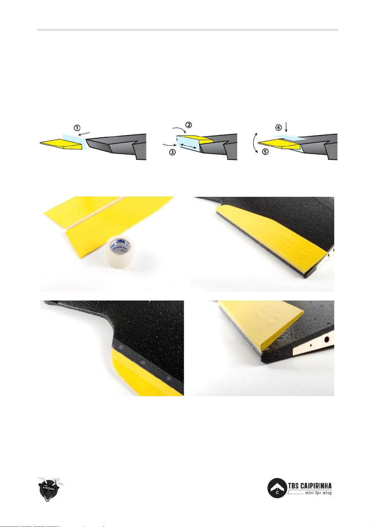
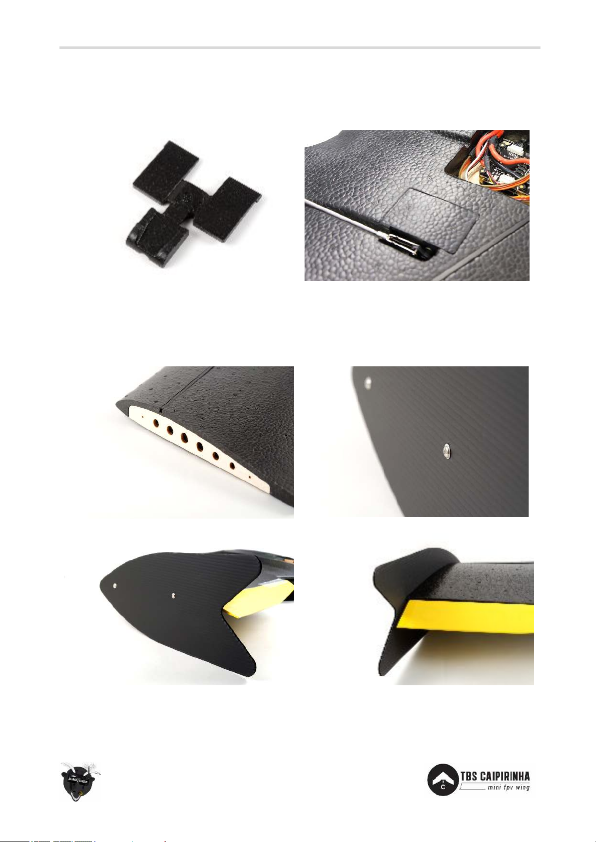
Tape elevons
Attaching the lightweight elevons to the wing is done using flexible tape. Any thin tape will do, but it is
recommended to use 3M Blenderm Hinge Tape or similar type.
Add one long piece of tape to the inside of the elevon and attach it to the wing. Bend the elevon down to
expose the topside. Add another long piece of tape to this side. Move the elevon up and down a few times
to compact and soften the hingje.
The inner end of the hinges should follow the arc from the frame, in-line with the frame. Leaving a small
cap between the winglet and elevon.
Page 17
17
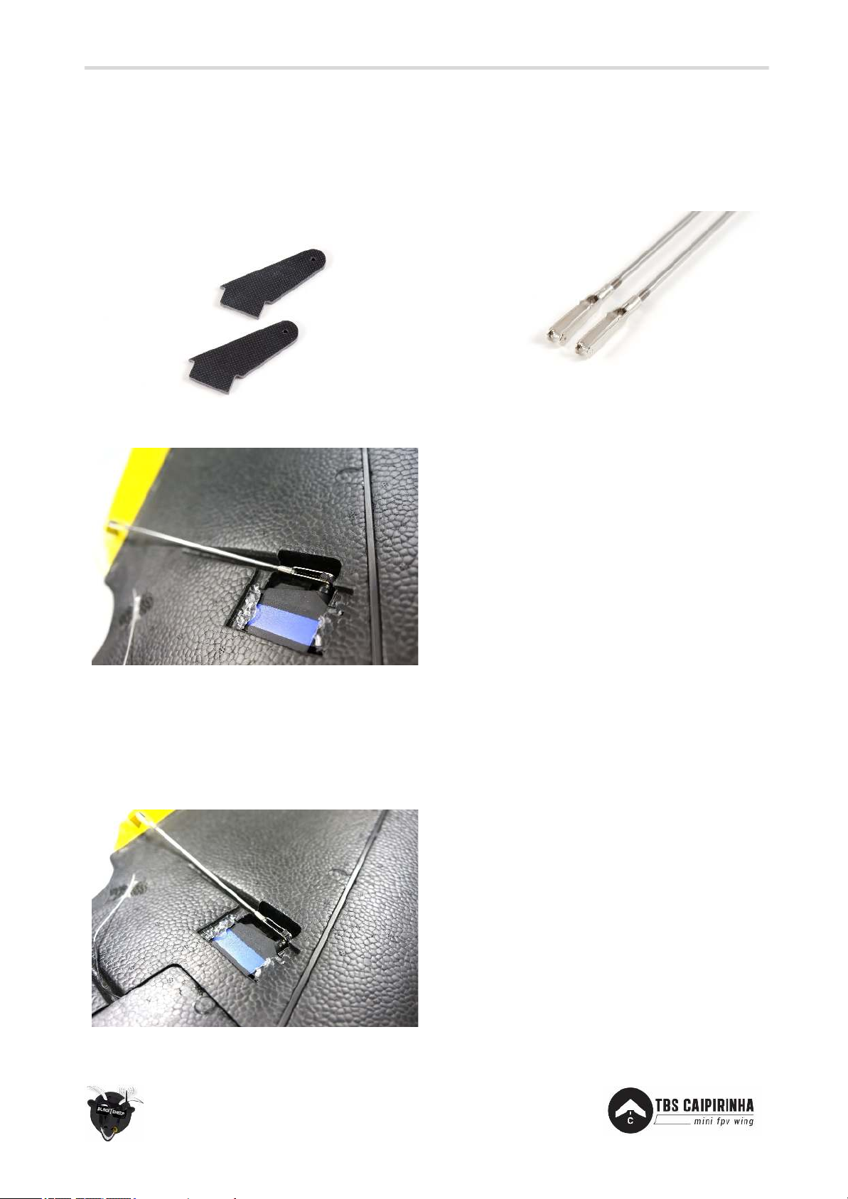
Elevon horns and control link
On the elevons, cut through the yellow film to open the pre-routed slot for the elevon horns. Add a decent
amount of CA/superglue to the horn and in the slot, insert the horn and make sure it is perpendicular to
the elevon and in-line with the servo horn.
Elevon servos
Add a band of masking tape or shrink tube around the servo. Attach the servo horn to the servo and put
the control link on the inner most hole for optimal mechanical range (resolution). Put a blob of hot glue or
CA glue in the corners of the servo compartment and install the servo.
Page 18
18
Small foam cover pads
For additional protection and completion, separate the three foam pieces and use hot glue to attach them
to the servo compartment and motor mount.
Attach winglets
Use the supplied washer-head screws to attach the winglets to the wood frame on either side of the wing.
The “deep side” of the winglet should face down underneath the wing, as shown in the photos below.
Page 19
19
Electronics installation
The TBS CAIPIRINHA II is designed to be flown light and with any FPV equipment, powertrain and battery
system, while reducing the build time to a minimum when building it with TBS-designed. Several central
cable channels keeps the wires neatly tucked away.
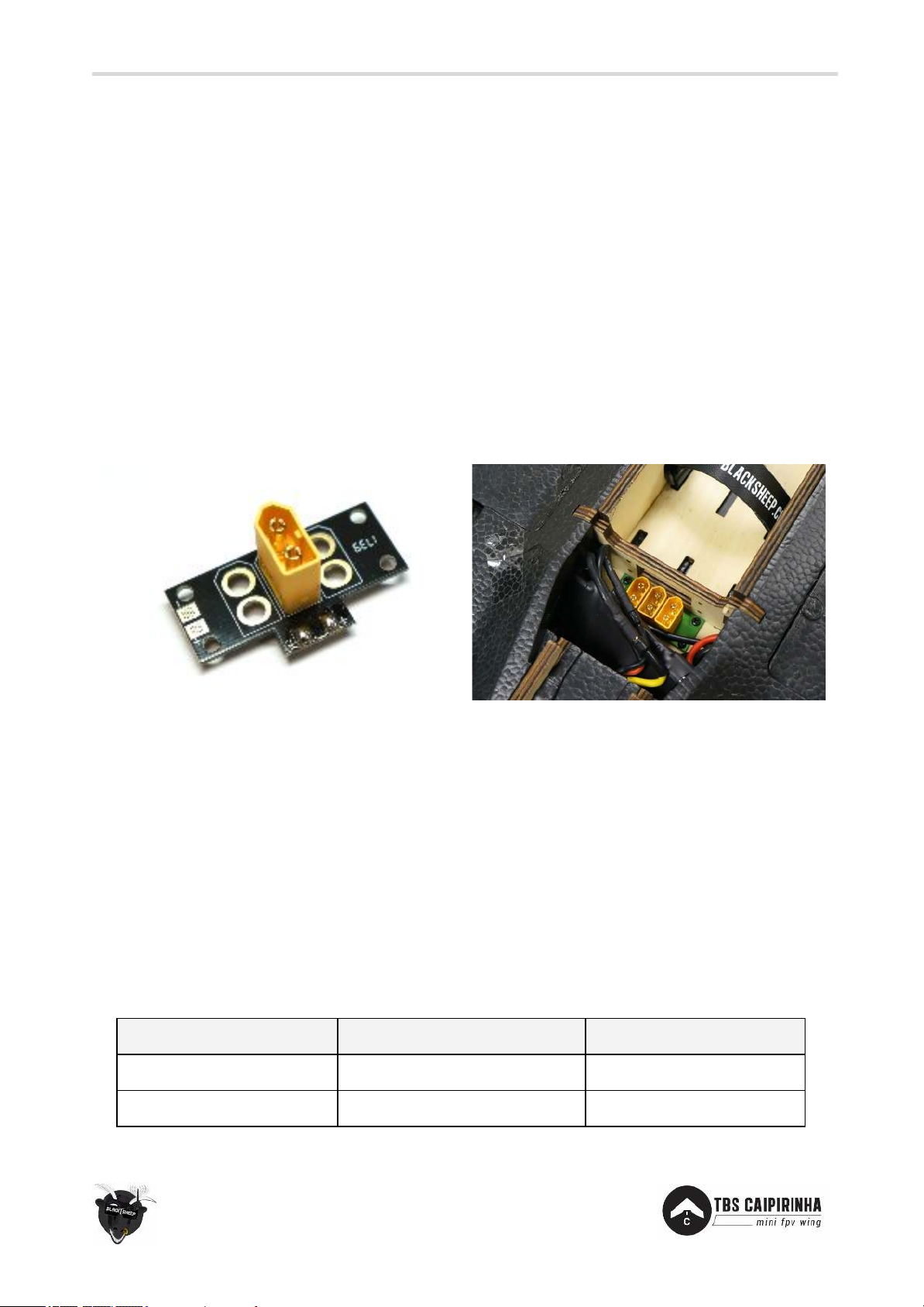
Central to the power powertrain is the power distribution board (PDB). It provides a quick way to connect
and replace the battery, no more loose power wires. Additional batteries can be connected to the free
XT60 footprints.
When picking out suitable equipment, keep lightweight and small size as key factors for a successful build.
The compartment layout is layed out to provide optimal separation between the R/C control link and VTX
video link. This extends range and minimized induced noise between the systems.
A detailed electronics installation diagram is available as an appendix to this manual.
Page 20
Channel
Travel range
Expo (zero being no expo)
Aileron (AIL)
+15 mm up, -13 mm down
60%
Elevator (ELE)
+13 mm up, -11mm down
50%
20
Dry-fit and wiring
Plan your setup and wiring in advance, draw it out and dry-fit or test everything on a table to make sure
everything checks out.
Longer wires translate to less range on a FPV system, so try to keep them short but do not overdo it! All
cables longer than 10cm should be shielded (e.g. use shielded USB cables for camera and VTx wires) to
guarantee optimal long range performance. Connectors are a very frequent point of failure in many FPV
systems. The wires should not be under tension while installed, leave ~2cm (1 inch) of excess wire just in
case.
Power distribution board
The included PDB makes it very easy to connect and swap out the battery(ies). It includes two additional
footprints to allow for up to three batteries to be connected in parallel.
Servos
Begin by centering the servos using a servo tester or R/C receiver with zero-trim. Add a single-armed servo
horn and make sure it is positioned perpendicular (vertical) to the side of the servo. Use sub-trim on the
transmitter (elevator and aileron channel), if necessary, to center it perfectly.
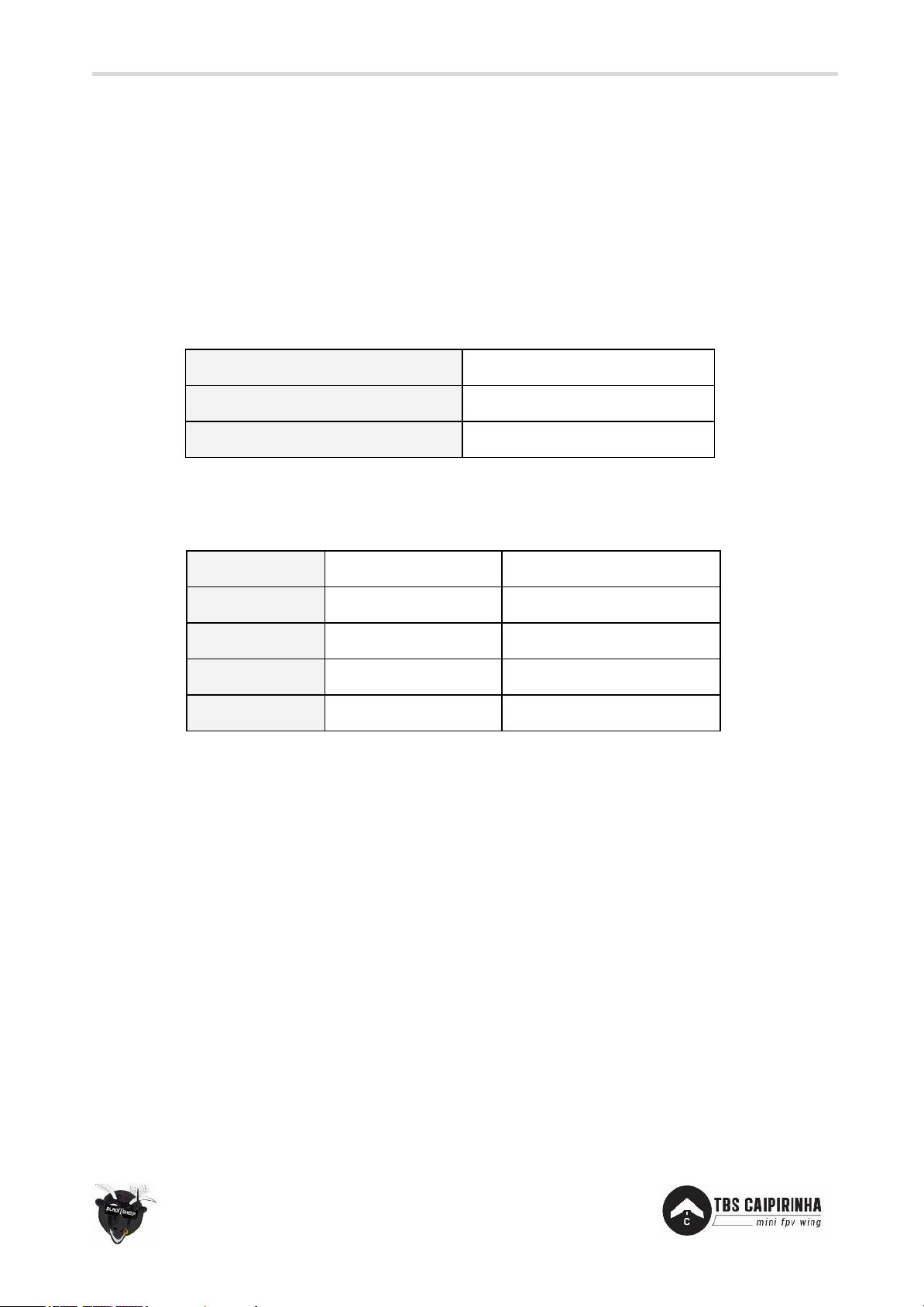
Program the travel range (deflection) and expo (sensitivity) for the elevator and aileron channels as listed
below to ease the flying experience. Too much deflection will introduce too much turbulence and hamper
the wing lift. To ease the launch of the wing, trim the elevator a few clicks pitch up from neutral to let it
pitch up from the ground. Be sure to program your servos to a negative (rearward-facing) 20% bias.
Reduce your throws to 60%. This ensures that the pushrod never touches the servo along its entire travel
Page 21
Channel 1
Throttle
Channel 2
Wing servo left / Aileron
Channel 3
Wing servo right / Elevator
Source
Wing [L or R]
-
Mid. Pos.
+20%
tad up elevon pitch
Max. Pos.
+60%
limit travel range up
Min Pos.
- 60%
limit travel range down
Direction
[Normal or reverse]
-
21
Receiver
Place the R/C receiver in the designated left electronics compartment and feed all wires through either of
the two channels - recommended to use the rear one.
Feed the antenna coax through the outlet cut and tape it in place, or use the unused antenna hole for a
more rigid antenna installation.
Set up the radio for delta wing mixing. The receiver should be connected as follows on a radio that outputs
TAER (Throttle Aileron Elevator Rudder) channel arrangement:
On the TBS TANGO FPV remote, you can limit the travel range by using the following settings on the servo
channels:
Also to make the stick movements less sensitive, add 60% aileron expo and 50% elevator expo.
TBS equipment
Both electronics compartments are layed out to provide ample space for installation of our FPVision, Wing
layer, and Core Pro boards, with space for the required BST- and receiver-wiring. Screw holes are provided
to fasten the boards using M3x6 screws.
Installing the TBS Wing Layer and TBS FPVision is done in a minutes. Even power to the ESCs can be
provided by the TBS FPVision layer, or in addition to a SBEC enabled ESC, all protected by the TBS Wing
layer.
Wing layer, FPVision and CrossFire micro
This combination provides an excellent build that provides a 800mW-capable Unify Pro 5G8 with twin
camera switcher, a digital current sensor, a fully customizable OSD to inform the pilot of the status of the
aircraft, TBS DCDC V2 to power to the servos and a direct servo output from CrossFire micro receiver.
Page 22
Setting
Value
Description
Voltage cut-off:
Low
Keep it flying until the bitter end
Cut-off mode:
Soft
Gradually decrease throttle range
Start mode:
Normal
Quick propeller spin-up
Break:
On
Prevent prop from spinning freely (drag)
Timing:
High
Match the motor sync
22
FPVision, Colibri iNav and CrossFire micro
Same as previous, but with TBS Colibri flight controller with iNav (http://inavflight.com) firmware and
non-TBS GPS puck for autonomous flight including Return To Home with a predefined climb height, circle
flight, and waypoints.
Speed controller
Install the ESC directly in the middle of where the motor mount slots begins. Use part of the adhesive
backed velcro to mount the ESC. Use bullet-connectors to connect to the motor. Connect the signal cable
to the R/C receiver and tuck it away in the rear cable channel. If the signal cable is too short, use an
extension servo cable to connect to the receiver. It is recommended to use 14 AWG rated wires to the PDB
or battery.
The recommended ESC settings are listed in the table below. Please refer to the ESC manual on how to
program these settings if it is not already pre-programmed.
Page 23

23
Brushless motor
With the motor attached to the motor mount, feed the wires through middle of the mount. If needed,
change the bullet-connectors to match the speed controller. Cover the wires with the small square foam
piece.
Plug in the wires to the ESC and remember to swap any two to change the direction of rotation, if needed.
Propeller
It is recommended to use a folding propeller to reduce drag while gliding and minimizing propeller
damage on landing.
Install the propeller using the following layering; prop adaptor (if used), propeller, washer and lock-nut.
Add a drop of threadlock on a non-lock nut. Make sure the top side (with printed logo) is facing the front of
the wing and that the propeller in the right direction. To change the direction of rotation of the motor,
switch 2 of the 3 cables going to the speed controller.
Before installing a regular non-folding propeller, balance it to reduce vibrations from propagating to the
HD recording camera.
Battery
The battery bay has two support straps to properly secure the battery and a cable exit cut-out for a nice
flush finish when using compatible batteries. Any size battery can be used, but it must be smaller than
W60 x H44 x L165 mm, suggested size W48 x H36 x L150 mm. And weight max. 550 grams and 525 grams,
respectively. It is recommended to use 14 AWG rated wires and XT60-connectors.
Page 24

24
Video transmitter
The video transmitter should preferably be installed the right side of the wing, next to the electronics bay.
If the bay is too small, outline the VTx and use a utility knife to remove the excessive foam. Mount the VTx
and support antenna portion of the unit using hot-glue to prevent dislodging the RF connector on impact.
Use the supplied adhesive cover to improve the aerodynamics and to protect the VTX.
Pilot camera
On the right side of the wing is a specially designed “pod” which houses the pilot camera. Any standard
26x26mm camera will fit, like the TBS ZEROZERO or RunCam Swift cameras. To fit the TBS69, make small
cuts in the back to remove foam or detach the heatsink. When using the stock mold, it is recommended to
use a 28mm or narrower lens for a better view (to keep the frame out of the view).
OSD (On Screen Display)
You can use an optional but recommended OSD add-on to get live readout on screen about the battery
voltage (V), current draw (A), total current consumption (mAh), receiver signal strength (%) and flight time
(minutes:seconds). This gives an essential overview of the system vitals while in flight. For a basic feature
set we recommend the TBS FPVision which provide all but the mentioned data points. For full featured
GPS-enabled system, check out the TBS CORE PRO with optional TBS GPS and TBS BLACKBOX logger.
Page 25
Video format:
NTSC
To enable 30/60fps
Resolution:
1080p60 or 2.4kp60
-
ProTune:
On
To enhance the footage
Color:
Flat
Better for post-editing
Sharpness:
Medium
-
ISO limit:
1600
-
Shutter speed:
Auto
-
25
HD camera
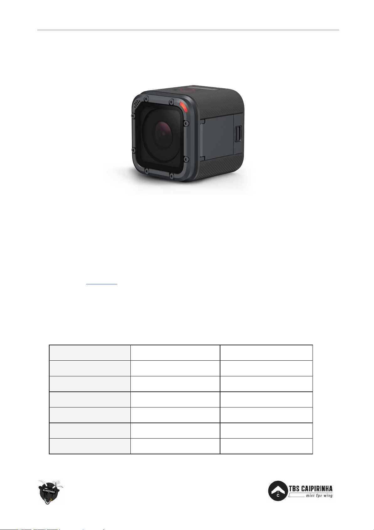
TBS CAIPIRINHA II is designed to sport a full fledged GoPro HERO Session (any model) camera to record
wonderful HD footage. Runcam 3 also fits, but it is not recommended because of poor video quality.
Mount it by sliding it into the designated “pod” on the left side of the wing. Secure it by fastening a velcro
strap through the slots on both sides.
Vibration free footage
To get rid any “jello”-effect, begin by eliminating the root cause of the vibrations. The primary culprit is
usually an unbalanced propeller. Fortunately, balancing the propeller is a relatively easy task. TBS offers a
Prop Balancer which is ideal for this purpose. More details on how to perform the balancing, see our
support forum at
Secondly, consider using the GoPro settings in the tables below for high quality and stable video.
fpvlab.com.
GoPro Session settings
To allow for better image quality and post-editing ability, we would recommend the following settings.
Page 26
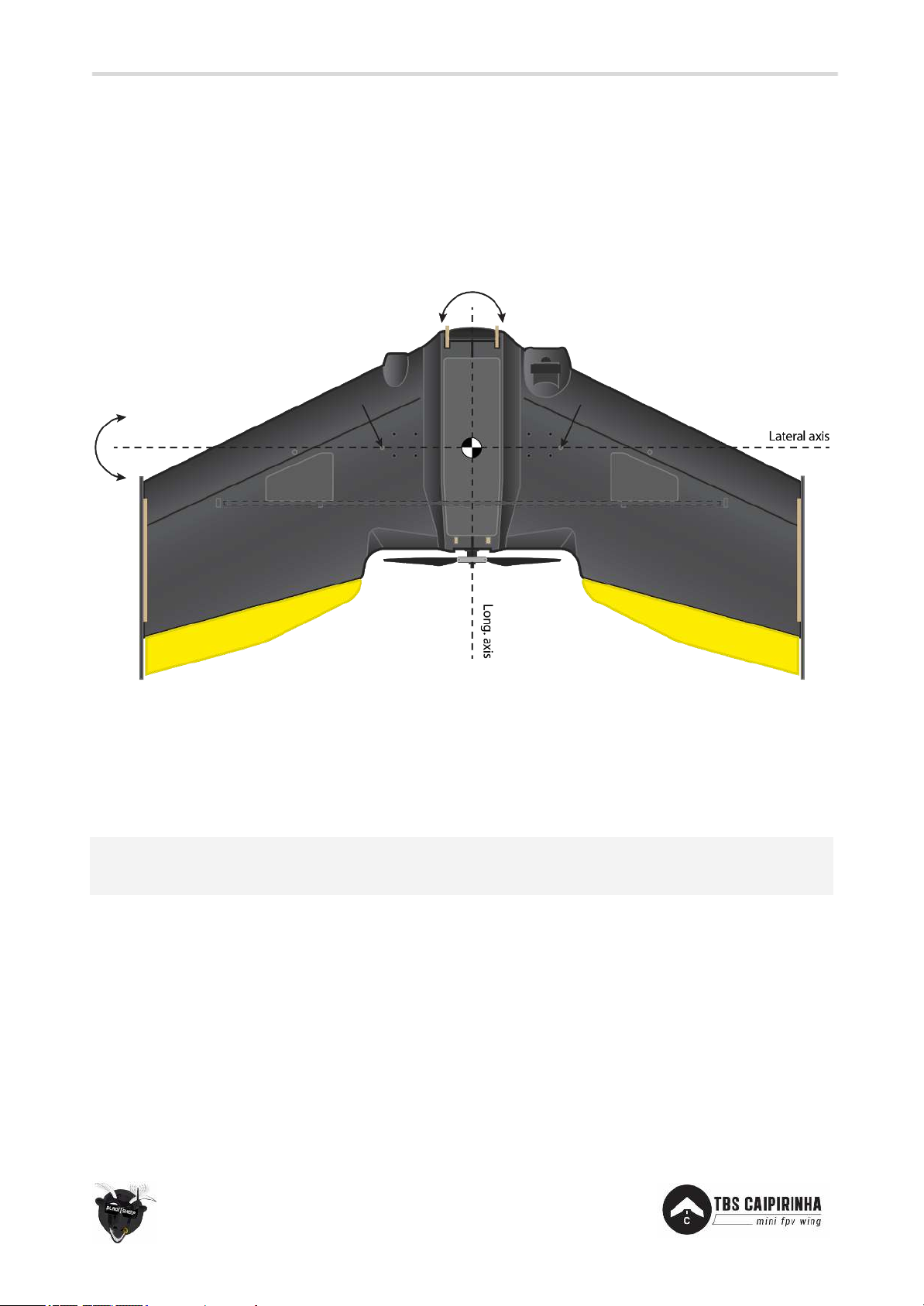
Note: Keep in mind that a slightly front heavy wing will fly, while a tail heavy wing will tend to fly very
poorly or not at all.
26
Center of Gravity optimization
For perfect Center of Gravity (CG), pick equipment that in the end makes the wing balance around the
indicated point. The CG is the point where the lateral and longitudinal axis balances.
Put a finger on the CG point and begin to balance a fully loaded wing. Ideally, when holding the wing in the
air at the CG spot it should be level and not dip to either side.
Balance the lateral (pitch) axis within the recommended CG spot. The longitudinal (roll) axis should be
balanced straight along the middle of the wing.
To adjust the CG, move the battery fore- or aft-ward a bit and check the CG again. Use a maker to
remember the exact battery position for later.
Page 27

27
Flight
First flight
Make sure that the controls are working properly. Check that the trim on the transmitter is centered
(zeroed). Pull the elevator control stick back and observe that both elevons move upward. Push the control
stick to the right and observe the right elevon moves up and the left elevon moves down. The propeller
should turn with the text facing forward and the straight sharp leading-edge cut into the air.
Launch
Hold the wing by the nose with your palm up over your head and your thumb wrapped around to the top.
Take a step or two forward and give the wing a good strong throw into the wind. A follow through with a
little finger tip will increase the launch speed. Move the throttle stick to the full forward position when the
wing is a comfortable distance from the ground.
For the first few flights ask someone to assist you, as this is a crucial step to get the wing off the ground
and trimmed out.
Trim
If the wing turns in either direction or pitches with no stick input, compensate by adding 2 or 3 clicks of
trim in the opposite direction. If the trim correction is not sufficient, check that the wing is balanced
around the CG spot (see the previous section) and that the both elevons are flush/level in neutral position.
Repeat the adjustments until the wing flies straight ahead in a glide with a slow sink rate to a sliding
landing.
FPV
After the wing has been adjusted to fly straight and properly, turn on the FPV equipment and do a range
test to verify that the video link is reliable. Launch the wing as normal, attain reasonable altitude flying
while Line-Of-Sight (LOS), and with the video goggles on your head, put them on (or turn to the display) to
engage in FPV flight. If the picture gradually weakens (noise blends in) or video suddenly drops, increase
altitude and return to home, as this normally indicates that you fly at the edge of the video range or
behind obstacles, respectively.
Page 28

28
Spare parts
You can either get spare parts directly from us (
team-blacksheep.com) or from one of our distributors and
retailers near you.
Our ever-growing list of retailers is published on the left at
team-blacksheep.com/shop.
Page 29

29
Good practices
We have compiled a list of all of practices which have been tried and tested in countless environments and
situations by the TBS crew and other experienced FPV pilots.
Follow these simple rules, even if rumors on the internet suggest otherwise, and you will have success in
FPV.
● Start with the bare essentials and add equipment one step at a time, after each new equipment
was added to proper range- and stress tests.
● Do not fly with a video system that is capable of outperforming your R/C system in terms of range.
● Do not fly with a R/C frequency higher than the video frequency (e.g. 2.4GHz R/C, 900MHz video).
● Monitor the vitals of your plane (R/C link and battery). Flying with a digital R/C link without RSSI is
dangerous.
● Do not use 2.4GHz R/C unless you fly well within its range limits, in noise-free environments and
always within LOS. Since this is most likely never the case, it is recommended to not use 2.4GHz
R/C systems for longer range FPV.
● Do not fly at the limits of video, if you see noise in your picture, turn around and buy a higher-gain
receiver antenna before going out further.
● Shielded wires or twisted cables only, anything else picks up RF noise and can cause problems.
● When using powerful R/C transmitters, make sure your groundstation equipment is properly
shielded.
● Adding Return-To-Home (RTH) to an unreliable system does not increase the chances of getting
your plane back. Work on making your system reliable without RTH first, then add RTH as an
additional safety measure if you must.
● Avoid powering the VTx directly from battery, step-up or step-down the voltage and provide a
constant level of power to your VTx. Make sure your VTx runs until your battery dies.
● Do not power your camera directly unless it works along the complete voltage range of your
battery. Step-up or step-down the voltage and provide a constant level of power to your camera.
Make sure your camera runs until your battery dies.
● A single battery system is safer than using two dedicated batteries for R/C and FPV. Two batteries
in parallel even further mitigate sources of failure.
● For maximum video range and law compatibility, use 2.4GHz video with high-gain antennas.
● When flying with R/C buddies that fly on 2.4GHz, or when flying in cities, it is perfectly possible to
use 2.4GHz video provided you stick to the channels that do not lie in their band (CH5 to CH8 for
Lawmate systems, available from TBS).
● Do not use diversity video receivers as a replacement for pointing your antennas, diversity should
be used to mitigate polarization issues.
Page 30
30
● Try to achieve as much separation of the VTx and R/C receiver as possible to lower the RF noise
floor and EMI interference.
● Do not buy cheap equipment unless it is proven to work reliably (e.g. parts falling off, multitudes of
bug fix firmware updates, community hacks and mods are a good indicator of poor quality and
something you do NOT want to buy for a safe system). Do some research before sending your
aircraft skyward to insure both you and the people around you stay safe.
Manual written and designed by ivc.no in cooperation with TBS.
 Loading...