

Page 1

TS-TwoWayTS-TwoWay
Bedienungsanleitung
Operating instruction
Mode d’emploi
Manuale di istruzioni
Mobilfunkgerät
Mobile Transceiver
Emetteur Récepteur
Ricetrasmettitore
Page 2
EnglishDeutsch
Français Italiano
TS-TwoWay
Bedienungsanleitung / Operating Instruction
Mode d’emploi / Manuale di istruzioni
Inhalt, Contents, Contenu, Indice
Seite, Page,
Page, Pagina
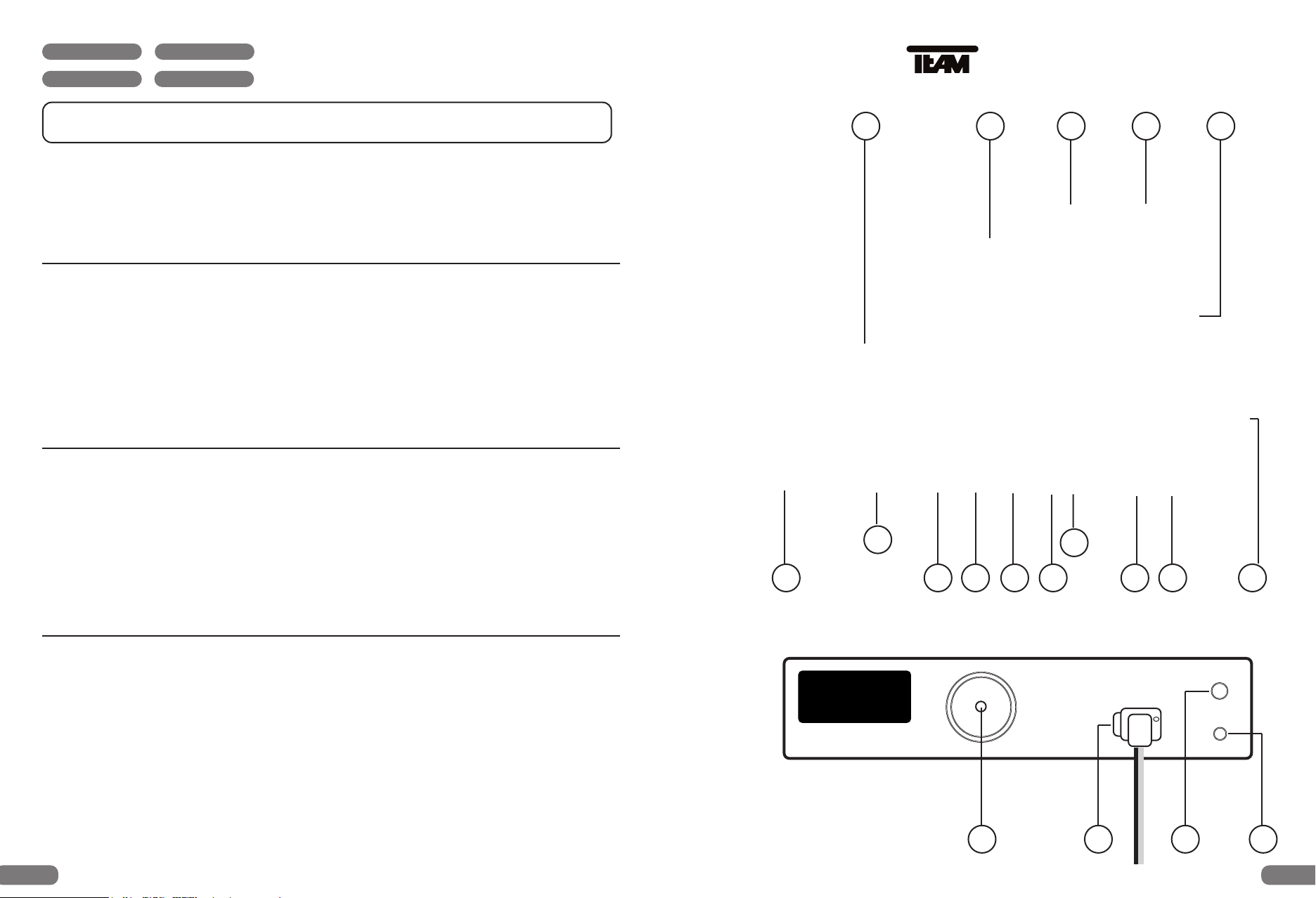
Bedienelemente 3 / 4
Controls 3 / 10
Eléments de commande 3 / 21
Comandi 3 / 26
Bedienungsanleitung 5 - 9
15
1 34
2
Operating instructions 11 - 15
9
8
Mode d’emploi 22 - 25
101112 1314
567
Manuale di istruzioni 27 - 31
Schaltplan / Schematic Diagram 16 - 17
Schema de principe / Schema Elettrico
PCB Layouts 18 - 19
DC 13.2 V
*
ANT
EXT-SP
S-METER
Technische Daten / Technical data 20
Caractéristiques / Caratteristiche techniche
16 17 1819
2 3
Page 3
Deutsch
Deutsch
TEAM TS-TwoWay
4040 / 4000
Bezeichnung der Bedienelemente
und Anschlüsse
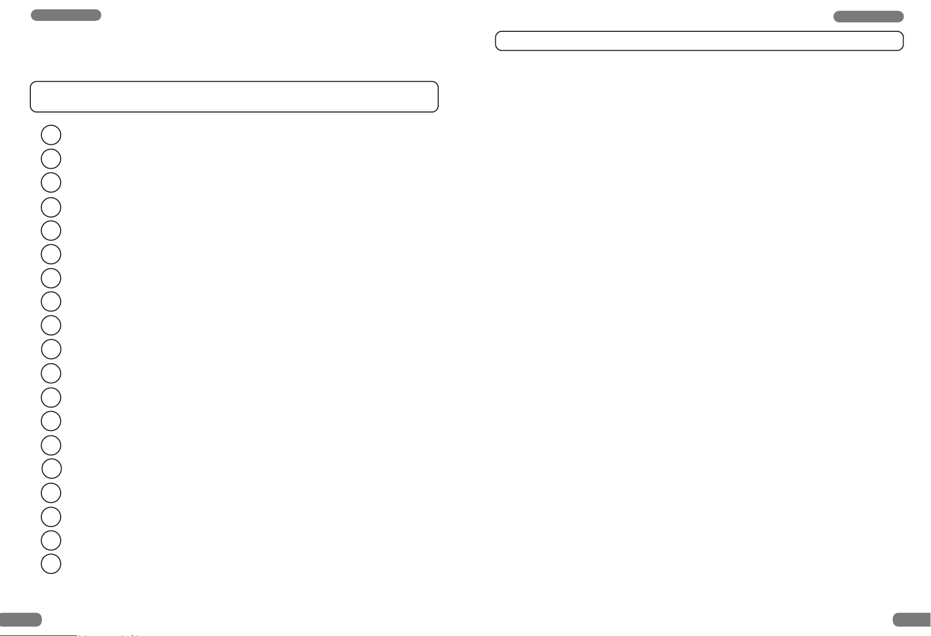
1
Sendetaste [ PTT ]
2
UP Kanalwahltaste [ ]
3
Down Kanalwahltaste [ ]
4
Rufsignaltaste [ Signal ]
5
Taste für Vorrangkanal 9 [ CH9 ]
6
Tasten für Betriebsart oder Empfangstonumschaltung [ MODE M1 / M2 ]
7
Taste für automatischen Kanalsuchlauf [ SCAN ]
8
Rauschsperreregler + ASQ [ SQUELCH ]
9
Lautstärkeregler / Ausschalter [ VOLUME / OFF ]
10
LED Kanalanzeige
11
LED Sendekontrollanzeige [ TX ]
12
LED Empfangskontrollanzeige [ RX ]
13
LED’s Betriebsart- oder Empfangstonanzeige [ M1 / M2 ]
Inbetriebnahme des TEAM TS-TwoWay 4040 / 4000
Montage einer CB-Funkantenne
Die Antenne gehört zu den wichtigsten Teilen einer Funkanlage. Die Wahl der Antenne und
des Montageortes ist von großer Bedeutung für die maximale Reichweite Ihrer Funkanlage.
Die folgenden Kriterien sollten Sie bei der Wahl des Antennenstandortes und der Montage
berücksichtigen. Allgemein gilt :
Die Antenne muß für den Funkbetrieb auf 27 MHz geeignet sein.
Der Standort der Antenne sollte möglichst hoch und unverbaut sein.
Das Antennenkabel sollte unbeschädigt und die Stecker ordnungsgemäß angeschlossen sein.
Das Antennenkabel sollte nicht zu stark geknickt werden.
Antennen mit einer größeren mechanischen Länge erzielen bessere Reichweiten.
Bei der Montage von Mobilantennen ist folgendes zu beachten:
Die Antenne sollte in der Mitte eines größeren Karosserieteils montiert werden.
Der Antennenfuß von Mobilantennen sollte möglichst guten Kontakt zu einer metallisch
gut leitenden Fläche des Karosseriebleches haben.
Außer der "festen Montage" einer Mobilantenne, bei der ein Loch in die Karosserie Ihres
Fahrzeuges gebohrt werden muß, gibt es noch weitere Möglichkeiten für die Montage, z. B.
Dachrinnenmontage, Halter für Montage an dem Kofferraumdeckel, Befestigung mit Magnetfuß oder Scheibenantenne.
Für den Aufbau einer Feststationsanlage empfiehlt sich die Montage einer stationären Dachantenne, z.B. TEAM ECO 050 oder ECO 200.
Um Störungen bei Radio und Fernsehempfang zu vermeiden sollte die CB-Antenne
nicht in unmittelbarer Nähe der Radio- und Fernsehantenne montiert werden.
Bei der Montage einer Dachantenne ist auf in der Nähe verlaufende Hochspannungs-
leitungen zu achten. " LEBENSGEFAHR "
Die Feststationsantenne muß über eine Blitzschutzeinrichtung angeschlossen werden.
Alle angeschlossenen Leitungen einschließlich der Antennenleitung dürfen eine Länge von
max. 3 Metern haben.
14
Mikrofonanschlußbuchse 6-polig ( GDCH-Norm )
15
Mikrofon mit Spiralkabel und 6 Pin Mikrofonstecker
16
Antennenanschlußbuchse SO 239 [ ANT ]
17
Buchse ( 3,5 mm ) für einen Zusatzlautsprecher [ EXT-SP ]
18
Buchse ( 2,5 mm ) für ein externes S-Meter [ S-Meter ]
19
Stromversorgungsanschluß [ DC 13,2 V ]
4 5
Antennenanschluß
Der PL-Stecker ( Typ: PL259 ) des Antennenkabels ( Koaxialkabel ) wird mit der Buchse
( 16 ) [ANT] an der Geräterückseite verbunden. Für eine einwandfreie Verbindung muß der
Überwurf des Steckers gut festgedreht werden. Ebenso ist auf eine ordentliche Verbindung
des Antennenkabels mit dem Antennenfuß zu achten. Nicht einwandfreie Verbindungen können zu einem Defekt des Gerätes führen und die Funkreichweite erheblich verringern. Die
Antennenanlage ( nicht im Lieferumfang enthalten ) sollte sehr gut an das Funkgerät
angepaßt sein, ansonsten wird ein Teil der Sendeleistung an der Antenne reflektiert und nicht
abgestrahlt. Das führt ebenfalls zu einer geringeren Reichweite der Funkanlage. Die Antenne
wird angepaßt durch Längenabgleich des Antennenstrahlers bzw. seiner Anpassungsvorrichtung auf ein minimales Stehwellenverhältnis, welches mit einem Stehwellenmeßgerät
( z.B. TEAM SWR 1180 P ) gemessen werden kann. Das Stehwellenmeßgerät muß nach der
Messung wieder aus der Antennenleitung entfernt werden.
Page 4
Deutsch
Deutsch
Montage
Wichtige Gesichtspunkte für die Wahl der Position bei einer Montage in einem KFZ sind :
keine Beeinträchtigung der Verkehrssicherheit,
gute Erreichbarkeit der Bedienelemente,
ausreichende Luftzirkulation, um eine Überhitzung des Gerätes im Sendefall zu
verhindern.
Es sollte berücksichtigt werden, daß die LED Kanalanzeige ( 10 ) gut ablesbar ist. Bei direkter Sonneneinstrahlung kann die Lesbarkeit der Anzeige beeinträchtigt werden. Die günstigste Montageposition sollte vor dem endgültigen Einbau überprüft werden. Mit Hilfe des
beiliegenden Montagebügels, ist eine schnelle Montage bzw. Demontage an verschiedenen
Stellen im Fahrzeug möglich.
Mikrofon
Das Mikrofon ( 15 ) wird mit dem 6 poligen Stecker in die Mikrofonbuchse ( 14 ) an der linken
Gerätefrontseite angeschlossen. Ohne Mikrofon ist kein Sende- oder Empfangsbetrieb
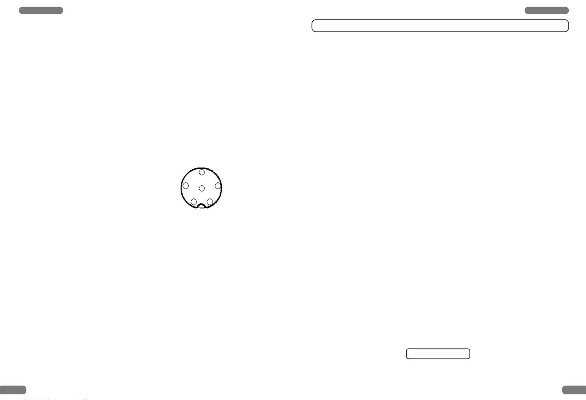
möglich. Die Mikrofonbuchse ist nach GDCH-Standard angeschlossen:
PIN 1 Modulation Pin Belegung :
PIN 2 Lautsprecher
PIN 3 PTT
PIN 4 UP/DOWN
PIN 5 Masse
3
2
1
4
6
5
PIN 6 +12 Volt
Ansicht von der Lötseite der Mikrofonbuchse bzw. Vorderansicht des Mikrofonsteckers
Funkbetrieb mit dem TEAM TS-TwoWay 4040 / 4000
1. Einschalten [ VOLUME ]
Vor dem erstmaligen Einschalten sollte der Rauschsperreregler ( 8 ) [ SQUELCH ] bis zum
Linksanschlag gedreht werden. Das Gerät wird eingeschaltet, indem Sie den Lautstärkeregler ( 9 ) [ VOLUME/OFF ] nach rechts drehen. Das Gerät befindet sich nun auf Kanal
9 in der Betriebsart FM. Der Hintergrund der Anzeige leuchtet nun auf und das
Empfängerrauschen wird hörbar. Stellen Sie die gewünschte Lautstärke ein.
2. Rauschsperre [ SQUELCH ]
Durch Rechtsdrehen des Rauschsperrereglers ( 8 ) [ SQUELCH ] kann das störende
Rauschen unterdrückt werden. Der Regler sollte nur soweit über den Stummschaltepunkt
gedreht werden, bis das Rauschen sicher unterdrückt ist. Weiteres Rechtsdrehen unterdrückt zunehmend schwache Stationen, aber auch stärkere Störsignale. Bei zu kritischer
oder zu fester Squelcheinstellung kann es bei SCAN Betrieb zur Nichterkennung eines
belegten Kanals kommen. Durch Drehen nach links, über die Schalterschwelle hinaus, wird
die Automatikstellung [ ASQ ] gewählt. Der Squelchschaltpunkt ist dann intern auf einen festen erprobten Wert eingestellt.
3. Kanalwahl [
Die Kanäle können durch Drücken der Kanalwahltasten ( 2 ) [ ] und ( 3 ) [ ] am
Mikrofon eingestellt werden. Die Anzeige erfolgt im LED-Display ( 10 ). Während des
Sendens kann kein anderer Kanal eingestellt werden. Die Kanalnummern werden wie ein
Ring durchlaufen, so daß die Kanäle aufwärts zählend von 1 auf 40, und abwärts zählend
von 40 auf 1 übergangslos gewählt werden können. Es kann nur auf übereinstimmenden
Kanalnummern und Modulationsart mit der Gegenstation Funkbetrieb aufgenommen werden.
]
4. Empfangstonumschaltung [ MODE ]
Stromversorgung
Verbinden Sie, bei ausgeschaltetem Gerät, das 2 polige Stromversorgungskabel ( 19 ) sorg-fältig
mit dem KFZ Bordnetz Ihres Fahrzeuges. Mit einem geeigneten Netzteil ( 13,2 V / 2,0 A ), z.B.
aus der TEAM Serie LabNT, kann das Gerät als Feststation betrieben werden. Bei dem Kauf
eines Netzteils sollten Sie darauf achten, daß dies für den Anschluß eines Funkgerätes
Die Version TS-TwoWay 4000 verfügt über eine Empfangstonumschaltung ( 6 ) [ MODE
M1 / M2 ]. Beim Einschalten ist eine helle Empfangstonwiedergabe eingestellt und wird
mit der LED-Kontrollanzeige ( 13 ) [ M1 ] angezeigt. Zum Umschalten für eine dunklere
Empfangstonwiedergabe drücken Sie die Taste ( 6 ) [ MODE ]. Die Einstellung des dunkleren Empfangstons wird mit der Kontrollanzeige ( 13 ) [ M2 ] angezeigt.
geeignet ist, da es ansonsten zu Störungen im Sende und Empfangsbetrieb durch Netzbrummen kommen kann.
5. Betriebsartumschaltung [ MODE ]
Der Gerätetyp TS-TwoWay 4040 verfügen über die Betriebsarten AM / FM und zwar :
Das Stromversorgungskabel sollte möglichst weit von störenden Aggregaten verlegt werden.
• TS-TwoWay 4040 über 40 Kanäle FM / 40 Kanäle AM
Achten Sie beim Anschluß des Stromversorgungskabels auf die richtige Polarität:
Beim Einschalten ist stets die Betriebsart AM auf Kanal 9 eingestellt. Durch Drücken der
SCHWARZ wird mit - MINUS / Masse des KFZ verbunden.
Taste ( 6 ) [ MODE ] schalten Sie das Gerät auf die Betriebsart FM um. Die Betriebsart wird
von den LED’s ( 13 ) angezeigt :
ROT wird mit 12 Volt + PLUS des KFZ Bordnetzes verbunden.
M1 = AM / M2 = FM
Nachdem die Antenne, das Mikrofon und die Stromversorgung sorgfältig angeschlossen sind,
kann der Funkbetrieb aufgenommen werden.
Der Gerätetyp TS-TwoWay 4000 ist nach europäischer Norm ETS 300 135 ausschließlich
mit der Betriebsart FM auf 40 Kanälen ausgestattet.
6 7
Page 5
Deutsch
Deutsch
6. Senden
Zum Senden wird die im Mikrofon eingebaute Sendetaste ( 1 ) gedrückt und für die Dauer
der Durchsage gehalten. Die Sendekontroll-LED ( 11 ) [ TX ] erscheint Das Mikrofon sollte
aus ca. 5 cm Entfernung mit normaler Lautstärke besprochen werden. Zu lautes oder zu leises Besprechen erschwert die Verständigung. Nach Beendigung der Durchsage muß die
Sprechtaste sofort wieder losgelassen werden und das Gerät schaltet auf Empfangsbetrieb
zurück. Es leuchtet die Empfangskontroll-LED ( 12 ) [ RX ].
7. Kanalsuchlauf [ SCAN ]
Bevor der Kanalsuchlauf gestartet wird, muß die Rauschsperre [ SQUELCH ] ( 8 ), wie
unter Absatz " 2 " beschrieben, eingestellt werden. Bei offener Rauschsperre kann das
Gerät die Such- und Haltfunktion nicht erfüllen. Durch Drücken des Tasters [ SCAN ] ( 7 )
startet der Kanalsuchlauf aufwärts zählend. Der Suchlauf bleibt auf dem ersten belegten
Kanal, auf dem die Rauschsperre durch Signalstärke automatisch geöffnet wird, stehen.
Er ist damit beendet.
8. Vorrangkanal 9 [ CH9 ]
Durch Drücken der Taste [ CH9 ] ( 5 ) ist eine Schnellwahl des Kanals 9 für Empfang und
Senden möglich. Im LED Kanaldisplay wird nun Kanal 9 angezeigt. Solange diese
Funktion gewählt ist, kann außer Senden durch Drücken der PTT-Taste keine andere
Eingabe vorgenommen werden. Durch nochmaliges Drücken der [ CH9 ] Taste wird diese
Funktion verlassen. Das Gerät schaltet auf den vorher eingestellten Kanal zurück.
9. Rufsignal
Wird die Rufsignaltaste ( 4 ) gedrückt wird ein Rufsignal ausgesendet und ist nur in der
Gegenstation zu hören, vorausgesetzt diese ist auf dem gleichen Kanal und Betriebsart
eingestellt.
Sicherheitshinweis
Bitte beachten Sie als KFZ-Fahrer beim Funkbetrieb auch die Bestimmungen der jeweils
gültigen Straßenverkehrsordnung. Für den Funkbetrieb während des Fahrens ist die Verwendung einer geeigneten Freisprecheinrichtung notwendig. Bei dem Betrieb des Geräts
wird Hochfrequenzenergie freigesetzt. Es muß daher ein entsprechender
Sicherheitsabstand zur Antenne eingehalten werden.
Allgemeine Hinweise
Das Gerät ist vor Feuchtigkeit und Staub zu schützen. Das Gerät niemals an Orten aufbewahren,
die einer starken Erhitzung und/oder direkter Sonneneinstrahlung ausgesetzt sein könnten.
Zur Gehäusereinigung ein weiches, fusselfreies Tuch verwenden. Zur Reinigung niemals
Lösungsmittel verwenden.
Service
Das Gerät darf nicht geöffnet werden. Eigenhändige Reparaturen oder Abgleich sind nicht
vorzunehmen, denn jede Veränderung bzw. Fremdabgleich können zum Erlöschen der
Betriebserlaubnis sowie der Garantie- und Reparaturansprüche führen. Bei Betriebsstörung
sollte das Gerät nicht benutzt werden. Trennen Sie die Stromversorgung ab. Liegt ein
Defekt vor, sollte auf jeden Fall der autorisierte TEAM-Fachhändler kontaktiert werden.
10. Anschlußbuchse für einen externen Zusatzlautsprecher [ EXT-SP ]
Das TS-TwoWay hat an der Geräterückseite eine Anschlußbuchse ( 17 ) für einen externen
Lautsprecher mit 4 - 8 Ohm Anschlußimpedanz ( z.B. TEAM TS-500 ). Bei 4 Ohm sollte die
Belastbarkeit des Lautsprechers 4 Watt betragen ( 3,5 mm ø Klinkenbuchse ). Bei Anschluß
des externen Lautsprechers wird der interne Lautsprecher abgeschaltet.
Zulassungen
Der Gerätetyp TS-TwoWay 4000 ist nach der Zulassungsvorschrift ETS 300 135 geprüft. Es
entspricht damit der Allgemeingenehmigung zum Errichten und Betreiben bestimmter CBFunkgeräte. Das Gerät ist bestimmt für die Inverkehrbringung in folgenden europäischen
Ländern : Belgien, Dänemark, Deutschland, England, Finnland, Frankreich, Großbritannien,
Italien, Litauen, Luxemburg, Niederlande, Norwegen, Österreich, Schweden, Schweiz,
11. Anschlußbuchse für ein externes Signal-Meter [ S-METER ]
An der 2,5 mm ø Klinkenbuchse ( 18 ) kann ein externes Signal-Meter zur Anzeige der relativen Empfangssignalstärke angeschlossen werden. Die Signalstärke einer empfangenen
Station kann entweder mit einem S-Meter gemessen oder nach persönlichem Eindruck
geschätzt werden. Zur Beurteilung des Empfangssignals stehen 9 S-Stufen zur Verfügung.
Spanien, Tschechische Republik und Ungarn.
Der Gerätetyp TS-TwoWay 4040 wurde zusätzlich nach der europäischen Vorschrift ETS 300
433 geprüft. Das Gerät ist bestimmt für die Inverkehrbringung in folgenden europäischen
Ländern : Belgien, Deutschland, Finnland, Frankreich, Niederlande, Polen, Portugal,
Slowakien
Eine S-Stufe entspricht 6dB. Dies bedeutet, daß die Empfängereingangsspannung bei dem
Wert S3 doppelt so hoch ist wie bei dem Wert S2. Mit den Radio-Werten kann der
Gegenstation mitgeteilt werden, wie gut die Sprachübertragung ist.
Entsorgung :
Bitte werfen Sie Ihr TEAM Altgerät nicht einfach auf den Müll, sondern senden Sie Ihr
Altgerät bitte portofrei zur fachgerechten Entsorgung an TEAM ein. TEAM wird anschließend
die umweltschonende Entsorgung Ihres Altgeräts für Sie kostenlos veranlassen. Bitte
Änderung der technischen Daten und der Ausführung sind ohne Vorankündigung vorbehalten.
machen Sie mit - der Umwelt zur Liebe.
8 9
Page 6
English
English
TEAM TS-TwoWay
4040 / 4000
Controls, displays
and connectors
1
Push to talk key [ PTT ]
2
UP channel selector key [ ]
3
Down channel selector key [ ]
4
Call tone key [ Signal ]
5
Priority channel selector key [ CH9 ]
6
Receiving tone key or AM/FM selector key [ MODE M1 / M2 ]
7
Channel scanning key [ SCAN ]
8
Squelch + ASQ [ SQUELCH ]
9
Volume control, On/Off [ VOLUME / OFF ]
10
LED channel display
Setting up the TEAM TS-TwoWay 4040 / 4000
Installation of a CB-antenna
The antenna is one of the most important parts of the equipment. The type of antenna and its
location has a great effect on the range of operation. Please consider the following criteria for
selecting the best location and installation of your antenna:
Make sure that the antenna is designed for radio operation on 27 MHz.
The location of the antenna should be as high as possible without any obstacles nearby.
The aerial cable should not be damaged and the plugs should be satisfactory connected.
Make sure that the antenna cable is not bent too strong.
The bigger the mechanical size of the antenna, the higher the range of operation.
When you install a mobile antenna please note the following advice:
The antenna should be fixed in the centre of a bigger part of the coachwork.
The mobile antenna coil should have the closest possible contact with a conducting metal-
lic surface of the bodywork of the car.
There are also some other possibilities to fix the antenna onto the car without the necessity
to drill a hole into the bodywork of your car, for example mounting the antenna onto the gutter, mounting the antenna onto a holder on the cover of the boot or using an antenna with a
magnetic foot or using a windscreen antenna.
For base-station operation we recommend a stationary antenna on the roof, for example the
TEAM ECO 050 or ECO 200.
11
Transmitting LED [ TX ]
Receiving LED [ RX ]
12
13
LED AM/FM or receiving sound [ M1 / M2 ]
14
Microphone socket 6 Pin ( GDCH-standard )
Microphone with curled cable and 6 Pin plug
15
16
Aerial connector SO 239 [ ANT ]
17
Socket ( 3,5 mm ) for external speaker [ EXT-SP ]
Socket ( 2,5 mm ) for external signal meter [ S-Meter ]
18
19
DC supply cord [ DC 13,2 V ]
10 11
Please don’t mount the CB antenna nearby a radio or TV antenna to prevent interference
of radio or TV reception.
Keep an eye on power lines running along nearby when mounting the antenna on the roof.
" DANGER "
The base-station antenna has to be connected via a lightning arrester.
All connected cables including the antenna cable must not exceed a length of 3 m.
Aerial Connection
Before pressing the transmit key, a suitable aerial must be connected. The PL259 plug of the
aerial cable ( coax ) is connected to the SO239 socket ( 16 ) [ANT] on the rear panel. Make
sure, that all plugs are firmly tightened and properly soldered. Unsatisfactory connections can
damage the radio and will reduce the range of operation.
The antenna should be matched with the radio, otherwise a part of the transmit power will be
reflected at the antenna and will not be radiated. This causes also a drop in the range of operation. The matching can be carried out by a length adjustment of the antenna radial for a minimal SWR ratio which can be measured by a SWR meter ( e. g. TEAM SWR 1180P ). After
the measurement the SWR meter should be removed from the antenna line.
Page 7
English
English
Installation
Always mount the transceiver where the switches are easy accessible. Important points of
view for the correct mounting position are:
no interference of the roadworthiness,
good access of the controls of the car,
sufficient air circulation to prevent overheating of the radio in transmit mode.
Please take into account that the LED-display is only good readable from a certain angle. An
intensive solar radiation can also affect the readability of the display. So it is recommended
to check the best position before the final installation. The unit can easily be fixed onto different positions in the car by using the enclosed mounting bracket.
Microphone
Plug the microphone into the 6 pin socket ( 14 ) on the front panel. Note it will only go in one
way round. No transmission and receiving is possible without the microphone. The pin
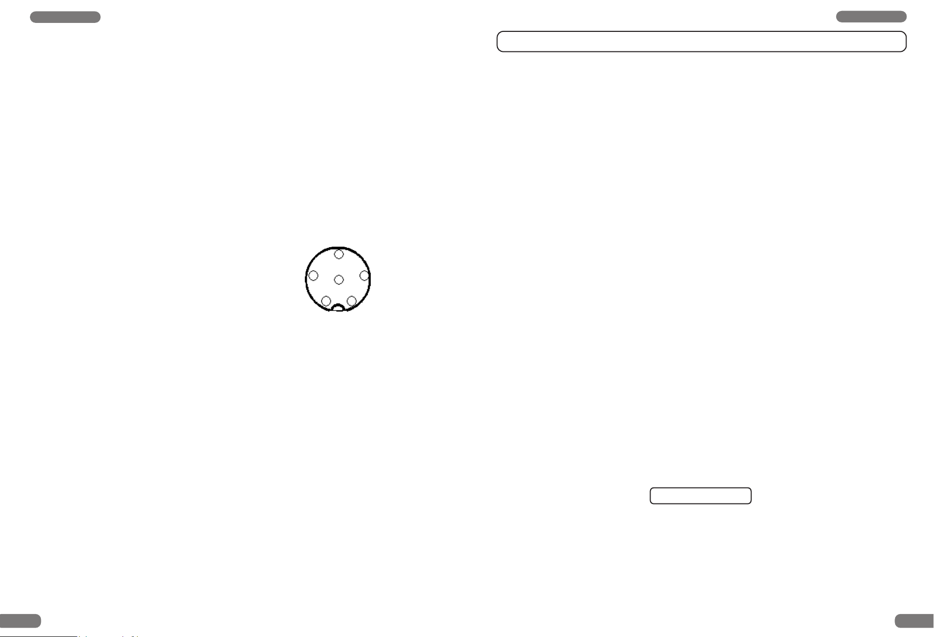
assignment of the GDCH standard microphone plug is given below:
PIN 1 Modulation Pin assignment
PIN 2 Speaker
PIN 3 PTT
PIN 4 UP/DOWN
PIN 5 Ground
3
2
1
4
6
5
PIN 6 +12 Volt
Solder side view of the microphone connector or top view of the microphone plug
Power source
Before connecting the power source to the fused DC power cable ( 19 ) the device must be
switched OFF by turning the volume control ( 9 ) [ VOLUME/OFF ] anticlockwise as far as the
stop and hearing a switching sound. The transceiver is designed to operate from a power
source of 13.8 volts DC, employing negative ground electrical system. For base-station operation use a suitable power supply ( 13,2 V / 2,0 A, e. g. TEAM LabNT ). The power supply
should be designed for operation with a transceiver, otherwise interference from the mains
may occur. Lay the cable as far as possible away from aggregates which can cause interference.
Operating of the TEAM TS-TwoWay
1. Switching On
Before switching ON set the control ( 8 ) [ SQUELCH ] to the counterclockwise stop. The
device is switched ON by turning the control ( 9 ) [ VOLUME ] clockwise to the centre position. The channel display ( 10 ) and the LED ( 12 ) [ RX ] light up. Adjust the receiver noise
with the volume control to the desired level. The internal S-Meter indicates the relative
received fieldstrength of incoming signals.
2. Squelch
By turning the squelch control [ SQUELCH ] ( 8 ) slowly clockwise, the background noise
can be suppressed. The squelch control should only be turned up enough to stop the
background noise on an unused channel. Turning the control further clockwise will
increasingly suppress interfering signals as well as weak stations.
The automatic squelch [ ASQ ] can be activated by turning the squelch control counterclockwise until the control clicks and the normal squelch function is switched off.
3. Channel Selection [
All channels can be selected by pushing the channel selector keys ( 2 ) [ ] and ( 3 )
] at the microphone to the desired channel. The channel number will be displayed in
[
the LED window ( 10 ). For communication with a partner CB station, both transceivers
must be adjust to the same channel and the same mode type FM.
4. Receiving Tone [ MODE ]
The type TS-TwoWay 4000 is equipped with a receiving tone key ( 6 ) [ MODE M1 & M2 ].
By switching on the set the receiving tone sounds bright and is indicated by LED ( 13 ) [ M1 ].
By pushing the mode key ( 6 ) the receiving tone is changing to a mellow sound in the loudspeaker. When the mellow sound is switched on the LED ( 13 ) [ M2 ] lights up.
5. Modulation Selection [ MODE ]
The type TS-TwoWay 4040 is availabe in AM / FM modulation :
• TS-TwoWay 4040 = 40 channels AM / FM
By switching on the set it is always on AM mode channel 9. By pushing key ( 6 ) [ MODE ]
the mode can be toggled between AM and FM. The selected mode will be indicated by
the LED’s ( 13 ).
]
Watch for the correct polarity of the DC power cable.
M1 = AM / M2 = FM
BLACK connect to - MINUS / ground of the car battery.
The type TS-TwoWay 4000 is equipped according to the European Telecommunication
RED connect to 12 volts + PLUS of the car battery.
Standard ETS 300 135 with 40 channels FM only.
After microphone, aerial and power source have been correctly connected, radio operation
can be undertaken.
12 13
Page 8
English
English
6. Transmitting [ PTT ]
To transmit depress and hold the key [ PTT ] ( 1 ). The TX control LED ( 11 ) lights up in red
colour. The sensitivity of the microphone ( 15 ) has been set to give good results speaking
normally at a distance of 2 - 4 inches. Speaking too loudly will cause distortions and make
the signal difficult to understand. While the set is in the transmit mode there is no key entry
possible and the receiver is muted. On completion of the transmission release the PTT key
and the set will revert to receiving mode. The RX LED ( 12 ) now lights up in green colour.
7. Channel Scanning [ SCAN ]
Before selecting the SCAN function set the squelch control [ SQUELCH ] ( 8 )according
to Para " 2 " because this function does not work with unmuted receiver. Depress now the
key [ SCAN ] ( 7 ). In the display the channels arestepping upwards. SCAN stops on the
first occupied channel, where a signal can trigger the squelch threshold. The SCAN function is terminated now.
8. Channel 9 [ CH9 ]
The priority channel 9 can be quickly selected by pressing the key [ CH9 ] ( 5 ). The channel number 9 lights up in the channel LED-display. No other function except transmitting
can be entered as long as the CH9 function is switched ON. Pressing CH9 again will cancel the function and the unit returns to the previous selected channel.
9. Call Tone
If you press the call key ( 4 ) a call tone will be transmitted and can be heard by the partnerstation providing it is switched on the same channel and same mode.
Safety Instruction
Drivers must keep attention about traffic rules by using the transceiver in a vehicle. Drivers
should use a handsfree microphone while driving.
The unit radiates RF energy in transmit mode. Please keep an eye on safety distance to
the antenna.
Servicing
The device must not be opened. Independent repairs or adjustment must not be carried out,
since each modification or unauthorised intervention will result in the cancelling of the operating permit and of the guarantee and repair claims.
Do not use the set if it seems not to function correctly. Disconnect the set from the DC power
source immediately. If there is a defect, the authorised TEAM specialist dealer or TEAM
must be contacted in every case.
10. External Speaker Jack [ EXT-SP ]
The TS-TwoWay has a 3.5 mm phone socket ( 17 ) on the rear panel to connect an external speaker of 4 - 8 ohm impedance. At 4 ohms the speaker load can be up to 4 watts
( e.g. TEAM TS-500 ). When the external speaker is connected the internal speaker will
be switched off.
General Precautions
Protect the set from humidity and dust. Do not store at places or in the sun where the temperature may rise and cause damage. The set can be cleaned by wiping with a soft cloth.
Do not use chemical products to clean the set.
11. External Signal Meter Jack [ S-METER ]
The TS-TwoWay offers also on its rear panel a socket ( 18 ) [ S-METER ] to connect an
external S-meter with a 2.5 mm plug. Please note that the external S-meter shows only
the relative fieldstrength of the incoming signal. The signal strength of a received station
can be either measured with a S-meter or estimated by the own impression. For the evaluation of the received signal there are 9 S-steps available. One S-step more is the same
as an increase of 6 dB. This means that the input signal strength at S3 is twice as high as
at S2. The 5 R-values can be used to inform the counter station about the sound quality
of the transmission.
Approvals
The type TS-TwoWay 4000 is approved according to the European standard ETS 300 135.
It is intended to be put into circulation in the following european countries: Austria, Belgium,
Croatia, Czech Republic, Denmark, Finland, France, Germany, Hungary, Italy, The
Netherlands, Norway, Lithuania, Luxemburg, Repulic of Slovenia, Spain, Sweden,
Switzerland, United Kingdom.
The type TS-TwoWay 4040 is additionally approved under ETS 300 433. The type TSTwoWay 4040 is approved for use in Switzerland only. TS-TwoWay 4040 is for distribution
and sale in: Belgium, Finland, France, Germany, Poland, Portugal, the Netherlands,
Republic of Slovakia
Specifictions are subject to change without any prior notice or obligation on the part of the manufacturer.
14 15
Page 9

TEAM TS-TwoWay S
chaltplan / Schematic Diagram / Schema de principe / Schema elettrico
16 17
Page 10
SUB PCB Layout TEAM TS-TwoWayMAIIN PCB Layout TEAM TS-TwoWay
18 19
Front PCB
Microphone PCB
MIC Socket PCB
SQ PCB
manual-TS-TwoWay.qxp 20.12.2006 11:11 Seite 18
Page 11
Français
Technische Daten / Technical Data/ Caractéristiques / Caratteristiche techniche
Allgemein / General / Général / Generali
Kanal Frequenz
Channel Frequency
Canaux Fréquence
Canale Frequenza
MHz
01 26.965
02 26.975
03 26.985
04 27.005
05 27.015
06 27.025
07 27.035
08 27.055
09 27.065
10 27.075
11 27.085
12 27.105
TS-TwoWay 4000 FM
TS-TwoWay 4040 AM/FM
Empfängerempfindlichkeit :
Receiver sensitivity :
Sensibilité du récepteur :
Sensibilità di ricevitore :
Zwischenfrequenzen :
Intermediate frequencies :
Fréquences intermédiaires :
Frequenze intermedie :
Squelch-Empfindlichkeit / Squelch sensitivity :
Sensibilité du squelch :
Sensibilità dello squelch :
NF-Ausgangsleistung / Audio output power :
Puissance de sortie audio :
Potenza d’uscita audio :
26.965 - 27.405 MHz
26.965 - 27.405 MHz
FM = 1,4 μV / EMK 20
dB (S+N+D)/N
AM = 1,2 μV / 60%;
20 dB (S+N+D)/N
1.ZF/IF 10.695 MHz
2.ZF/IF 455 KHz
1,6 μV - 2,0 μV
1,9 W / 8 Ω
(10% THD)
13 27.115
14 27.125
15 27.135
16 27.155
17 27.165
Sendeleistung / TX output power :
Puissance d’émission :
Potenza di trasmisione :
Hub / Deviation / Déviation / Deviazione :
FM max. 4 W / 50 Ω
AM max. 1 W / 50 Ω
max. 2 KHz / FM
18 27.175
19 27.185
Modulationsgrad / Mod.-Degree :
95 % max. AM
20 27.205
21 27.215
22 27.225
23 27.255
24 27.235
25 27.245
26 27.265
27 27.275
Frequenztoleranz / Frequency tolerance :
Tolérance de fréquence :
Tolleranza di frequenza :
Ober-/Nebenwellenunterdrückung :
Harmonic / spurious suppression :
Réjection des (non) harmoniques :
Sopprressione delle (non) armoniche :
max. ± 600 Hz
_
<
4 x 10⁻⁹W
_
<
2,5 x 10⁻⁷W
28 27.285
29 27.295
30 27.305
31 27.315
32 27.325
33 27.335
34 27.345
35 27.355
36 27.365
Stromaufnahme / Current consumption :
Consommation / Consumo di corrente :
Betriebsspannung / Power Supply Voltage :
Alimentation / Alimentazione :
Abmessung / Dimensions :
Dimensions / Dimensioni :
980 mA / TX FM
580 mA / TX AM
150 mA / RX
max. 15 V /
13,2 V nom.
165 x 70 x 40 cm
37 27.375
38 27.385
39 27.395
Gewicht / Weight :
Poids / Peso :
674 gr. ( excl. mic.)
40 27.405
TEAM TS-TwoWay
4040 / 4000
Elements de commande
affichages et connecteurs
1
Touche d’émission [ PTT ]
2
Touche de sélection de canaux [ ]
3
Touche de sélection de canaux [ ]
4
Touche de la tonalité [ Signal ]
5
Touche de canal 9 [ CH9 ]
6
Touche de ton de réception ou commutateur AM/FM [ MODE M1 / M2 ]
7
Touche de recherche de canaux [ SCAN ]
8
Réglage du squelch + ASQ [ SQUELCH ]
9
Réglage du volume et arrêt [ VOLUME / OFF ]
10
Affichage LED du canal 1-40
11
Indicateur d’émission [ TX ]
12
Indicateur de réception [ RX ]
13
Indicateur AM/FM ou ton de réception [ M1 / M2 ]
14
Prise du microphone 6 broches ( standard GDCH )
15
Microphone avec câble et fiche 6 broches
16
Connecteur d’antenne SO 239 [ ANT ]
17
Prise pour haut-parleur externe ( 3,5 mm ) [ EXT-SP ]
18
Prise pour S-mètre externe ( 2,5 mm ) [ S-Meter ]
19
Câble d’alimentation [ DC 13,2 V ]
20 21
Page 12
Français Français
Montage
Mise en service du TEAM TS-TwoWay
Prenez en considération les aspects suivants pour le choix de la position dans votre voiture:
Connexion de l’antenne
L’antenne est une partie très importante d’une station émettrice. Le type d’antenne et le lieu
de placement sont d’une grande importance pour la portée de votre émetteur récepteur. Les
critères suivantes sont déterminantes pour le choix du lieu de placement et la montage de
l’antenne.
Faites attention de maintenir une certaine distance de sécurité à l’antenne à cause de la
radiation radio-électrique.
Utilisez une antenne prévue pour 27 MHz.
Choisissez l’endroit de l’antenne le plus haut que possible et le moins barré que possible.
Le câble d’antenne ne doit être pas endommagé et les connecteurs doivent être rac
cordés en bonne forme.
Le câble d’antenne ne doit être coudé pas trop fort.
Les antennes avec une longueur plus grande atteindent une portée plus grande.
Prenez en considération les conseils suivants pour la montage des antennes mobiles:
Placez l’antenne au milieu d’une part plus grande de la carrosserie.
Le pied d’antenne mobile doit avoir le contact le mieux possible à une surface bien con
ductible de la carrosserie.
En dehors de la "montage fixe" de l’antenne mobile, qui demande la perçage d’un trou dans
la carrosserie de votre voiture, il y a des autres possibilités pour l’installation, par exemple l’utilisation d’une antenne de gouttière ou une antenne de fenêtre d’auto, la montage à un support sur le coffre ou la montage avec un pied magnétique.
Pour l’utilisation de l’appareil en station fixe, il est recommandé d’installer une antenne sur
comble stationnaire, par exemple TEAM ECO 050 ou ECO 200.
Pour éviter des dérangements de la réception de radiodiffusion et de télévision il est con-
seillé de ne pas placer l’antenne CB dans le voisinage immédiat de l’antenne de réception
de radiodiffusion et de télévision.
En installant d’une antenne sur comble il faut faire attention à des lignes à haute tension
qui passent à proximité. " DANGER DE MORT "
L’antenne stationnaire doit être reliée à un dispositif de protection contre la foudre.
Tous câbles reliés peuvent avoir une longueur de 3 m au maximum.
aucune atteinte de la sécurité routière,
bonne accessibilité des éléments de manipulation,
suffisante circulation d’air pour empêcher un surchauffage de l’appareil en cas de
transmission.
Faites attention que l’affichage LED ne soit que bien lisible d’un angle certain. Une insolation
forte peut aussi porter atteinte à la lisibilité de l’afficheur. Vérifiez la position plus avantageuse
avant la montage définitive.
A l’aide du support de montage livré vous pouvez installer votre appareil facilement à
plusieurs places dans la voiture.
Microphone
Brancher la fiche 6 broches a la prise du microphone ( 15 ) placée sur la partie gauche au
panneau avant de l’appareil. Sans microphone, il n’est pas possible d’émettre ou de recevoir.
Le connecteur du microphone est raccordé selon le standard GDCH:
PIN 1 Modulation Assignation des broches
PIN 2 Haut-parleur
PIN 3 PTT
PIN 4 UP/DOWN
3
2
1
4
6
5
PIN 5 Masse
PIN 6 +12 Volt
Vue du côté de soudure du connecteur ou vue du côté avant de la fiche du microphone.
Connexion de l’alimentation
Lorsque l’appareil est hors service, branchez le câble d’alimentation à 2 pôles situé au panneau arrière de l’appareil ( 19 ) de la manière suivante:
NOIR sera branché à la borne - négative ou masse
ROUGE sera branché à la borne + positive 12 Volt.
Pour l’utilisation en station fixe branchez votre appareil sur une alimentation régulée ( 13,2 V /
Connexion de l’antenne
Le connecteur PL du type PL259 du câble d’antenne ( coax ) doit être raccordé à la prise
d’antenne ( 16 ) [ ANT ] placé au panneau arrière. L’écrou à raccord doit être vissé à fond
2,0 A , par exemple TEAM LabNT ). L’alimentation régulée doit être qualifiée pour le service
à un émetteur récepteur, sinon on risque des dérangements par ronflement dû au courant
alternatif en émission et réception.
pour une bonne jonction. Il faut également veiller au bon raccordement du câble coaxial à
l’antenne. Un mauvais raccord peut entraîner des pertes et peut également endommager
l’appareil. La disposition de l’antenne doit être adaptée bien au émetteur récepteur, sinon une
Après la connexion de l’antenne, du microphone et de l’alimentation, votre émetteur récepteur est maintenant prêt à fonctionner.
part de la puissance d’émission soit reflétée à l’antenne et ne soit pas rayonnée. Ça réduit
aussi la portée de l’appareil. L’accord d’antenne est réalisée par l’adaption de la longueur du
radiateur ou son dispositif d’accord au minimum du rapport d’amplitude de puissance, qui
peut être mesurer avec un mesureur de réflexions ( par exemple TEAM SWR 1180P ).
22 23
Page 13
Français Français
Mise en service du TEAM TS-TwoWay 4040 / 4000
1. Mise en march :
Avant d’allumer votre appareil, veillez à ce que le réglage ( 8 ) [ SQUELCH ] soit tourné
vers la gauche sans le laisser s’enclencher. En tournant l’interrupteur et réglage du volume ( 9 ) [ VOLUME/OFF ] vers la droite l’appareil est allumé. Réglez le volume maintenant à un valeur agréable.
2. Reglage du squelch [ SQUELCH ]
Tournez lentement le réglage de la suppression de bruit [ SQUELCH ] ( 8 ) dans le sens
des aiguilles d’une montre jusqu’à ce que le bruit de fond disparaisse. Dans cette position, le récepteur sera silencieux s’il n’y a pas des stations sur le canal. L’arrivée de signaux radioélectriques supprimera automatiquement l’action du squelch. Lorsque l’on
tourne le bouton plus loin encore, il faut des signaux plus forts pour ouvrir le squelch. Pour
cette raison faites les ajustements sur un canal libre. En tournant le réglage de la suppression de bruit vers la gauche jusqu’à ce qu’il s’enclenche vous activez la fonction
squelch automatique. Le seuil de réponse du squelch est ainsi ajusté à une valeur fixe.
3. Choix du canal [
Les canaux 1 - 40 peuvent être choisis à l’aide des boutons [ ] ( 2 ) et [ ] ( 3 ) au microphone. Le numéro du canal est indiqué dans la fenêtre d’affichage LED ( 10 ). Un contact
radio est seulement possible si l’autre station se trouve sur le même canal ou la même
fréquence, et si elle utilise la même modulation.
4. Choix de ton de réception [ MODE ]
Avec la touche ( 6 ) [ MODE ] du TS-TwoWay 4000 vous pouvez changer le ton de réception grave ou aigue. La lampe témoin ( 13 ) [ M1 ] s’éclaire à l’usage du ton aigue et [ M2 ]
à l’usage du ton grave.
5. Choix de la modulation [ AM/FM ]
En appuyant sur la touche ( 6 ) [AM/FM] de TS-TwoWay 4040 vous changez la modulation qui est indiquée dans la fenêtre d’affichage par les LED indicateures ( 13 ) [ FM ou
AM ].
• TS-TwoWay 4040 = 40 canaux AM / FM
Le premier canal après été mise en marche sera canal 9 en opération AM.
L’appareil TS-TwoWay 4000 est admis par la norme européenne ETS 300 135 avec 40
canaux seulement en opération FM .
5. Emettre [ PTT ]
Pour émettre on actionne durant toute la communication la touche d’émission ( 1 ) du
microphone. La lampe témoin ( 11 ) TX s’éclaire en rouge. Vous parlez à voix normale à
environ 5 à 10 cm du microphone ( 15 ). Parle à voix plus forte ou plus douce peut diminuer la compréhension chez votre correspondant. A la fin de votre message relâchez la
]
M1 = AM / M2 = FM
touche ( 1 ). L’appareil se remet alors en position réception. Maintenant la lampe témoin
( 12 ) RX s’éclaire en vert. Par principe on transmet et reçoit alternativement avec l’autre
station sinon il n’est pas possible de se faire comprendre. Si un canal est déjà occupé
vous passeriez mieux à l’autre canal.
6. Recherche des canaux [ SCAN ]
Avant d’actionner cette fonction il faut tourner le bouton du squelch [ SQUELCH ] ( 8 )
jusqu’à ce que le bruit de fond disparaisse. La fonction SCAN n’est pas exécutable avec
le squelch ouvert. Maintenant appuyez sur le commutateur de recherche des canaux
[ SCAN ] ( 7 ). Les canaux défilent vers le haut dans la fenêtre d’affichage. L’appareil s’arrête lorsque le niveau d’un signal dépasse le réglage du squelch. La recherche des
canaux est terminée par là.
7. Canal 9 [ CH9 ]
En pressant la touche [ CH9 ] ( 5 ) vous choisissez directement le canal 9 comme canal
prioritaire. Le numéro 9 apparaît dans l’affichage. Pendant cette fonction est active toutes
les autres fonctions sont bloquées excepté [ PTT ]. En pressant à nouveau sur la touche
[ CH9 ] ( 5 ) vous arrêtez la fonction et l’appareil se remet sur le canal initial.
8. Tonalité d’appel
En pressant la touche de la sonnette téléphonique ( 4 ) le signal d’appel sera émis et est
alors seulement perceptible chez l’autre station.
9. Haut-parleur externe [ EXT.SP ]
Le TS-TwoWay est équipé avec une prise ( 17 ) [EXT.SP] au panneau arrière pour la connexion d’un haut-parleur externe avec une fiche 3,5 mm. L’impédance peut être entre 4 et
8 Ohm. Un haut-parleur avec 4 Ohm consomme au maximum 5 Watt ( par exemple TEAM
TS-500 ). L’haut-parleur incorporé est coupé lorsque la prise est utilisée.
10. S-mètre [ S.METER ]
Il y a la possibilité de raccorder un S-mètre additionnel avec une fiche 2,5 mm à la prise
( 18 ) [S.METER] au panneau arrière. On peut ou mesurer l’intensité de champs relative
d’une station reçue avec un S-mètre ou l’estimer par l’impression personnelle. Pour l’appréciation du signal reçu il y a 9 échelons à disposition. Un échelon S correspond à une
démarche de 6 dB. Ca veut dire que le voltage à l’entrée du récepteur soit le double à S3
comme à S2. Avec les valeurs R on peut renseigner le correspondant sur la qualité de la
transmission de la parole.
Service
L’appareil ne peut pas être ouvert. Toute modification ou manipulation de l’appareil aura pour
conséquence une annulation de l’autorisation de service et la non-conformité avec les dispo-
sitions. Toute perturbation ne peut être supprimer que par du personnel spécialisé et autorisé.
Homologation
L’appareil TS-TwoWay 4000 est admis par ETS 300 135. Il est à vente dans les pays suivants: L'Autriche, Belgique, Croatie, République Tchèque, Danemark, Finlande, France,
Allemagne, Hongrie, Italie, les Pays Bas, Norvège, Lithuanie, Luxembourg, Repulic de la
Slovénie, Espagne, Suède, Suisse, Royaume-Uni.
L’appareil TS-TwoWay 4040 est admis par ETS 300 135 et ETS 300 433. TS-TwoWay 4040
est à vente en: La Belgique, Finlande, France, Allemagne, Pologne, Portugal, les Pays Bas,
République de la Slovaquie
24 25
Page 14
Italiano Italiano
TEAM TS-TwoWay
4040 / 4000
Comandi, indicatori
e connettori
1
Tasto di trasmissione [ PTT ]
2
Tasto di selezione dei canali [ ]
Tasto di selezione dei canali [ ]
3
4
Tasto della suoneria [ Signal ]
Canale prioritario [ CH9 ]
5
Tasto commutatore AM/FM o suono di ricezione [ MODE M1 / M2 ]
6
Tasto per l’attivazione della funzione SCAN [ SCAN ]
7
Regolatore della soppressione del fruscio + ASQ [ SQUELCH ]
8
Regolatore del volume e marcia / arresto [ VOLUME / OFF ]
9
Indicatore LED del canale 1-40
10
Indicatore di trasmissione [ TX ]
11
12
Indicatore di ricezione [ RX ]
Indicatore AM/FM o suono di ricezione [ M1 / M2 ]
13
Presa del microfono ( standard GDCH )
14
Connessione del TEAM TS-TwoWay 4040 / 4000
Montaggio dell’antenna
L’antenna è una delle parti più importanti di un impianto radio. La scelta dell’antenna e della
posizione di montaggio è di grande importanza per la portata massima del vostro impianto
radio. Dovreste considerare i seguenti criteri per la scelta della posizione dell’antenna e del
montaggio. In generale:
Per la protezione della radiazione delle onde radioelettrici è necessario di tener una
distanza certa all’antenna.
L’antenna dovrebbe essere idonea al funzionamento a 27 MHz.
La posizione dell’antenna dovrebbe essere il più in alto possibile, ed in zona libera da
impedimenti.
Il cavo dell’antenna dovrebbe essere intatto e i connettori regolarmente collegati.
Il cavo dell’antenna non dovrebbe essere troppo piegato.
Con antenne di maggiore lunghezza meccanica è possibile ottenere portate migliori.
Per il montaggio di antenne mobili è necessario rispettare le seguenti avvertenze:
L’antenna dovrebbe venire installata nel mezzo di una parte abbastanza grande della car-
rozzeria.
La base dell’antenna mobile dovrebbe avere il miglior contatto possibile con una superfi-
cie della lamiera della carrozzeria dotata di buona conducibilità.
Oltre al “ montaggio fisso “ dell’antenna mobile, per il quale è necessario perforare la carrozzeria del vostro veicolo, esistono anche ulteriori possibilità per il montaggio, p.es. montaggio sulla canalina di scolo del tetto, supporti per il montaggio sul coperchio del portabagagli, fissaggio con base magnetica o l’antenna per il parabrezza.
Per un impianto fisso consigliamo il montaggio di un’antenna stazionaria sul tetto, p.es. la
TEAM ECO 050 o ECO 200.
Per evitare disturbi alla ricezione televisiva e radiofonica, l’antenna non dovrebbe venire
installata nelle vicinanze immediate dell’antenna televisiva e radiofonica.
Nel corso dell’installazione di un’antenna sul tetto bisogna fare attenzione alla presenza di
eventuali linee ad alta tensione nelle vicinanze. “ PERICOLO DI VITA “
L’antenna fissa deve venire collegata ad un parafulmine.
La lunghezza dei cavi connessi non deve essere più di 3 metri.
Microfono con cavo e spina
15
16
Presa dell’antenna SO 239 [ ANT ]
Presa per altoparlante esterno ( 3,5 mm ) [ EXT-SP ]
17
18
Presa per misuratore - S esterno ( 2,5 mm ) [ S-Meter ]
19
Cavo di alimentazione [ DC 13,2 V ]
26 27
Connessione del antenna :
Il connettore PL ( tipo: PL259 ) del cavo dell’antenna ( cavo coassiale ) va inserito nella presa
( 16 ) [ANT] sulla parte posteriore dell’apparecchio. Per una connessione perfetta avvitare
bene la ghiera di fissaggio del connettore. Provvedere analogamente ad una connessione
accurata del cavo dell’antenna con la base. Connessioni imperfette possono danneggiare
l’apparecchio e ridurre sensibilmente la portata dell’impianto.
L’antenna deve venire adattata molto accuratamente all’impianto radio, altrimenti una parte
della potenza di trasmissione viene riflessa e non emessa. Anche questo porta a una
riduzione della portata dell’impianto. L’antenna viene adattata tramite un’allineamento lungitudinale del’irradiatore, oppure attraverso il suo sistema di adattamento, ad un rapporto minimo di onde stazionarie, che può venire misurato con un apparecchio apposito ( p.es. TEAM
SWR 1180P ).
L’indicatore del rapporto di onde stazionarie dovrebbe venire rimosso dalla linea dell’antenna dopo la misurazione.
Page 15
Italiano Italiano
Microfono
Il microfono viene collegato attraverso il connettore a sei poli alla presa del microfono ( 14 )
sulla parte sinistra anteriore dell’apparecchio. La ghiera di sicurezza del connettore del microfono deve venire avvitata alla presa del microfono! Senza il microfono non è possibile
trasmettere nè ricevere.
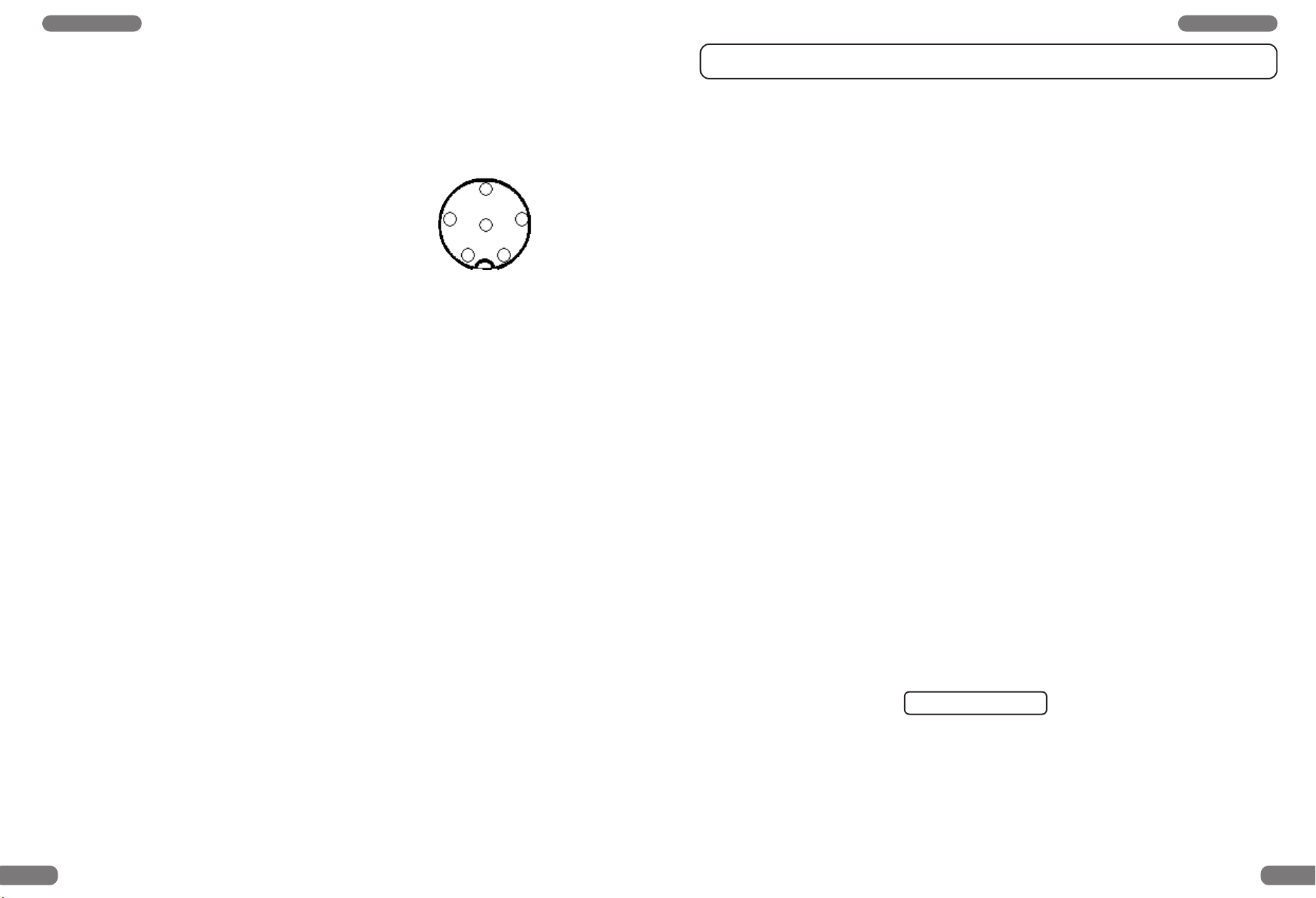
La presa del microfono è connessa secondo lo standard GDCH ( società dei produttori
tedeschi di impianti per radioamatori ):
PIN 1 Modulazione PIN-OUT
PIN 2 Altoparlante
PIN 3 PTT
PIN 4 UP/DOWN
PIN 5 Massa
3
2
1
4
6
5
PIN 6 +12 volt
Vista della presa del microfono dalla parte della saldatura dei contatti ossia vista frontale del
connettore del microfono.
Alimentazione
Assicurarsi che l’apparecchio sia spento girando il regolatore del volume e marcia / arresto
( 9 ) [VOLUME/OFF] a destra fino a fine corsa. L’allacciamento del cavo di alimentazione alla
parte posteriore dell’apparecchio ( 19 ) avviene nel modo seguente :
NERO viene connesso con ( - ) NEGATIVO/MASSA del veicolo.
ROSSO viene connesso con 12 volt ( + ) POSITIVO della rete di bordo
del veicolo. Se la tensione è continuamente presente, l’ultimo
canale selezionato prima dello spegnimento dell’apparecchio viene
immagazzinato. Trasmettendo da una stazione fissa va usato un
alimentatore appropriato ( 13,2 V / 2,0 A ).
Montaggio
Criteri importanti per la scelta della posizione di montaggio nel veicolo sono:
nessuna riduzione della sicurezza stradale,
buona raggiungibilità dei comandi,
sufficiente circolazione d’aria per evitare un surriscaldamento dell’apparecchio durante la
trasmissione.
Uso del vostro TEAM TS-TwoWay 4040 / 4000
1. Accensione [ VOLUME ]
Prima della prima attivazione il regolatore soppressione rumore ( 8 ) dovrebbe venire girato verso sinistra fino al fine corsa senza azionare il interruttore. L’apparecchio si accende
girando il regolatore volume e marcia / arresto ( 9 ) verso destra fino al volume desiderato. Ad impianto acceso la spia [ RX ] ( 12 ) risplende in verde è nello indicatore LED del
canale viene indicato canale 9.
2. Soppressione del fruscio [ SQUELCH ]
Girare lentamente il comando soppressione rumore ( 8 ) [ SQUELCH ] in senso orario fino
alla scomparsa del rumore di fondo. In questa posizione la ricevente sarà silenziosa se non
si odono stazioni sul canale. L’arrivo di segnali radioelettrici interromperà automaticamente l’azione dello squelch. Ruotando il bottone oltre occorreranno segnali più forti per
inattivare lo squelch. Per questa ragione, effettuare le regolazioni su di un canale libero.
Girando il regolatore verso sinistra fino al azionamento del interruttore sceglie la funzione
squelch automatico. La soglia di soppressione rumore è ora regolata interno a un valore
fisso.
3. SELEZIONE DEL CANALE [
/
I canali 1 - 40 possono venire selezionati usando i tasti [ ] ( 2 ) o [ ] ( 3 ). Il canale
selezionato viene indicato nel display ( 10 ). L’indicazione riporta il numero del canale.
Durante la trasmissione non è possibile selezionare un altro canale. Si può stabilire una
radiocomunicazione con un’altra stazione solo se i canali rispettivamente selezionati e le
modulazioni sono corrispondenti.
4. Suono di ricezione [ MODE ]
Con il tasto ( 6 ) [ MODE ] del TS-TwoWay 4000 viene selezionata il suono di ricezione
chiaro o oscuro. La spia ( 13 ) [ M1 ] si accende al suono chiaro e [ M2 ] al suone oscuro.
5. Selezione della modalità di funzionamento [ AM / FM ]
Con il tasto ( 6 ) [MODE ] del TS-TwoWay 4040 viene selezionata la modalità di modulazione. La modalità di modulazione selezionata viene indicata la spina ( 13 ) [ AM o
FM ]
• TS-TwoWay 4040 = 40 canali AM / FM
]
Bisogna tener conto del fatto che il display LED si legge bene soltanto sotto un determinato
angolo di visuale. La leggibilità dell’indicazione può venire ridotta anche dalla luce diretta del
M1 = AM / M2 = FM
sole. Prima dell’installazione definitiva si dovrebbe individuare la posizione di montaggio più
opportuna.
La staffa di montaggio allegata rende possibile il montaggio in luoghi diversi all’interno del
Dopo il collegamento ad una fonte di tensione l’apparecchio si trova sempre sul canale
9 nella modalità di funzionamento AM.
veicolo.
Dopo aver collegato in modo accurato l’antenna, il microfono e l’alimentazione, si può iniziare.
28 29
Page 16
Italiano Italiano
5. Transmissione [ PTT ]
Per trasmettere, premere durante l’intera comunicazione il tasto trasmissione ( 1 ), sul
microfono. La spia RX/TX ( 11 ) si accende in rosso. Si parli con voce normale a 5 - 10
cm circa dal microfono ( 15 ); parlando più piano o più forte si rischia di diminuire la comprensione da parte dell’interlocutore. A fine messaggio, rilasciare il tasto ( 1 ).
L’apparecchio torna allora in modo ricezione. Bisogna trasmettere e ricevere alternandosi
con la stazione con cui si è in comunicazione, altrimenti una comprensione reciproco non
è possibile. Se un canale è già occupato, è meglio usare un altro canale.
6. Ricerca canale [ SCAN ]
Prima di attivare la ricerca, la soppressione del fruscìo [ SQUELCH ] ( 8 ) deve venire
regolata come descritto al paragrafo “2”. Con la soppressione del fruscìo disattivata l’apparecchio non è in grado di compiere la funzione di ricerca e selezione. Premendo il tasto
[ SCAN ] ( 7 ) si inizia la ricerca in senso crescente. La ricerca si ferma al primo canale
occupato sul quale la soglia di soppressione del fruscìo viene superata automaticamente
dalla intensità del segnale. A questo punto la ricerca è terminata.
7. Canale 9 prioritario [ CH9 ]
Spingendo il tasto [ CH9 ] ( 5 ) è possibile selezionare velocemente il canale 9 per la
ricezione e la trasmissione. Nella finestra LED viene indicato il canale 9. Se la funzione è
attivata, tutte le altre funzioni sono bloccate eccetto trasmettere. Spingendo un’altra volta il
tasto [ CH9 ] ( 5 ) questa funzione viene disattivata. L’apparecchio torna al canale selezionato precedentemente.
8. Tasto della suoneria
Premendo il tasto suoneria telefonica ( 4 ) si trasmissione il segnale di appello verrà
trasmesso, e si lo sentirà nella stazione interlocutrice.
Assistenza technica per il TEAM TS-TwoWay
Non si devono effettuare riparazioni o tarature in proprio, perché ogni modifica o intervento
effettuato da estranei porta alla decadenza del permesso di uso e dei diritti di garanzia e
riparazione. Nel caso si riscontri un difetto contattare comunque il rivenditore autorizzato
TEAM.
Omologazione del TEAM TS-TwoWay
L’apparecchio TS-TwoWay 4000 è omologato conformemente ad ETS 300 135.
L’apparecchio può venire messo in vendita nei paesi seguenti:
L'Austria, Belgio, Croatia, Repubblica Cecia, Danimarca, Finlandia, Francia, Germania,
Italia, Paesi Bassi, Norvegia, Lituania, Lussemburgo, Repulic della Slovenia, Spagna,
Svezia, Svizzera, Ungheria, Regno Unito.
L’apparecchio TS-TwoWay 4040 sono omologati conformemente ad ETS 300 135 e ETS
300 433. L’apparecchio può venire messo in vendita nei paesi seguenti:
Belgio, Finlandia, Francia, Germania, Paesi Bassi, Polonia, Portogallo, Repubblica di
Slovacchia
9. Altoparlante supplementare [ EXT.SP ]
La presa di collegamento per un altoparlante esterno ( 17 ) [EXT.SP] si trova sulla parte
posteriore dell’apparecchio ( jack da 3,5 mm ). L’impedenza di connessione dovrebbe
essere di 4 - 8 ed il carico ammissibile dell’altoparlante di almeno 5 Watt ( p.es. TEAM
TS-500 ). Collegando l’altoparlante esterno quello interno viene disattivato.
10. Misuratore - S [ S.METER ]
Esiste la possibilità di collegare un misuratore - S esterno alla presa ( 18 ) [ S.METER ]
sulla parte posteriore dell’apparecchio con un connettore jack da 2,5 mm. Il misuratore S esterno segnala solo la intensità relativa del campo in ricezione. La intensità del segnale di una stazione ricevuta può venire misurata con un misuratore - S oppure può venire
stimata secondo l’impressione personale. Per la valutazione del segnale in ricezione sono
a diposizione 9 livelli S. Un livello S corrisponde a 6 dB. Questo significa che la tensione
di entrata del ricevitore con il valore S3 è alta il doppio che non con il valore S2. Con i val-
version 01/07
ori Radio si può comunicare all’altra stazione la qualità della trasmissione della voce.
Nachdruck oder Vervielfältigung auch Auszugsweise nur mit ausdrücklicher
Genehmigung von TEAM Electronic GmbH.
30 31
Page 17
TEAM Electronic GmbH Tel. 069 / 300 950 0
Bolongarostrasse 88 Fax 069 / 31 43 82
D-65929 Frankfurt/Main eMail [email protected]
 Loading...