

Team TS-9M Operating Instruction
Bedienungsanleitung
Operating Instruction
Manual de Instrucción
Manuale d’istruzioni
Mode d’emploi
Handleiding
- Full Multi Norm
DE, PL, EC, EU, EI, UK
- EC CEPT
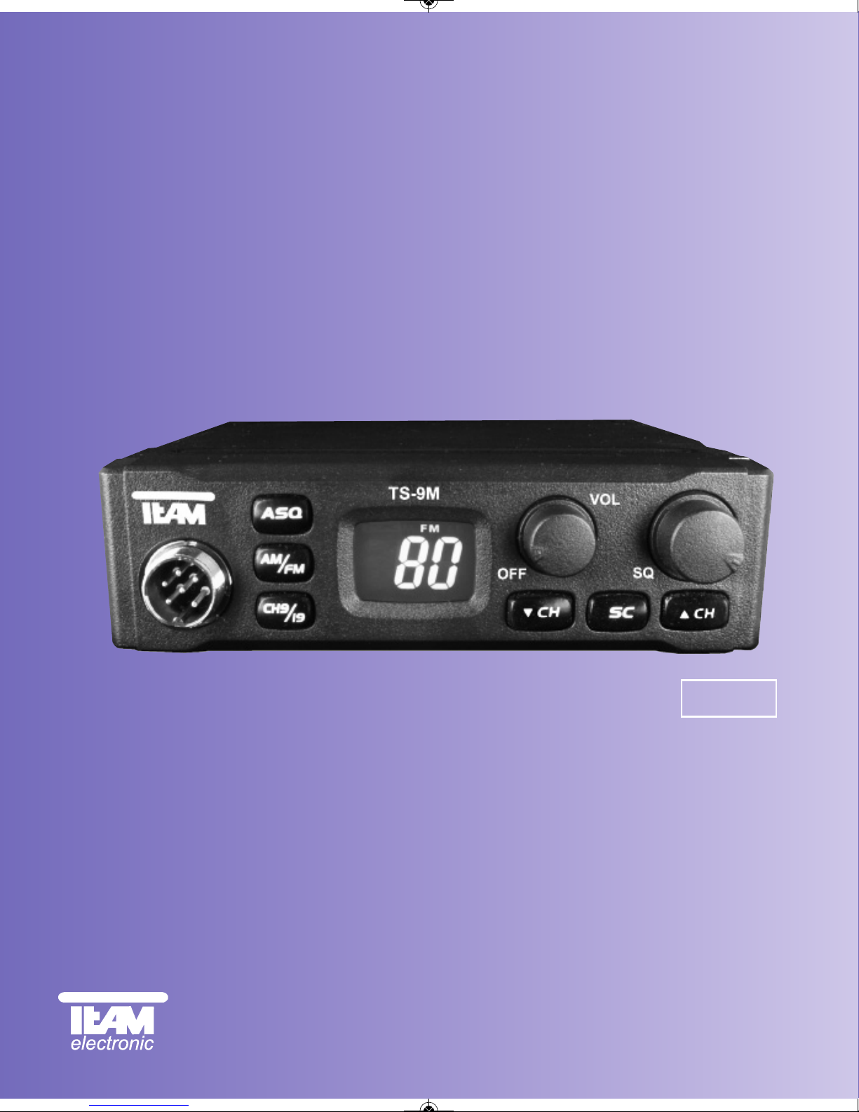
TS-9M
CB-Mobilfunkgerät
CB Mobile Radio
Transmisor móvil CB
Cb émetteur récepteur
Ricetrasmettitori
CB mobile zender
12 Volt
ts-9m_manual_2:RoadCOM manual.qxd 05.09.2011 13:11 Seite 1
3
12
11
8
10
4
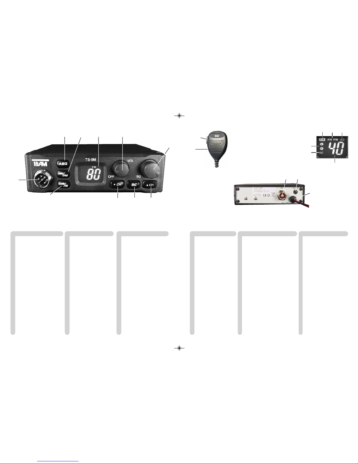
1 Micrófono con cable rizado y
conector 6 pin
2 Botón pulsar para hablar [ PTT ]
3 Indicador LCD
3A SC exploración de canal
3B H/L AM potencia de salida
3C TX modo de transmisión
3D número de canal
3E modo de modulación AM/FM
3F AQ silenciador automático
4 Selección de modulación [ AM/FM ]
5 Botón de selector canal abajo [ q ]
6 Botón de selector canal arriba [ p ]
7 Botón de Squelch automático [ ASQ ]
8 Interruptor de Squelch manual [ SQ ]
9 Control de volumen, Encendido/
Apagado
10 scan [ SC ]
11 Botón de prioridad canal 9 / 19
[ CH9 / 19 ]
12 Conector de micrófono 6 pin
( GDCH estándar)
13 Conector de antena aéreo
SO239
14 Cable de alimentación DC
15 Conector Jack ( 3,5 mm ) para
altavoces externos
Español página 24 - 29 Netherland pagina 42 - 47
1 Microfoon met spiraal kabel
en 6 pin plug
2 Push to talk toets [ PTT ]
3 LCD display
3A SC kanalen zoeken
3B H/L AM zendvermogen
3C TX mode ontvangst
3D kanaalnummer
3E mode modulatie AM/FM
3F AQ automatische ruisonderdrukking
4 Omschakelen van de
modulatie [ AM/FM ]
5 Kanaal selectie omhoog [ q ]
6 Kanaal selectie omlaag [ p ]
7 automatische squelch [ ASQ ]
8 Squelch bediening [ SQ ]
9 Volume bediening, Aan/Uit
schakelaar [ Off / Vol ]
10 Scan [ SC ]
11 Kanaal 9 / 19 priority toets
[ CH9/19 ]
12 Microfoon aansluiting 6 pin
( GDCH standaard )
13 Antenne aansluiting SO239
14 DC kabel
15 Jack aansluiting ( 3.5 mm )
voor externe luidspreker
1 Mikrofon mit Spiralkabel +
6-Pol Stecker
2 Sendetaste [ PTT ]
3 LCD-Anzeige
3A SC Kanalsuchlauf
3B H/L AM TX-Sendeleistung
3C TX-Sendemodus
3D Kanalanzeige
3E Betriebsart AM/FM
3F AQ Automatische Rauschsperre
4 Modulationsart [ AM/FM ]
5 Kanalwahlschalter runter [ - ]
6 Kanalwahlschalter hoch [ p ]
7 auto. Rauschsperre [ ASQ ]
8 manuelle Rauschsperre [ SQ ]
9 Lautstärkeregler / Ein-/Ausschalter
10 Kanalsuchlauf [ SC ]
11 Vorrangkanaltaste für Kanal 9/19
[ CH9/19 ]
12 Mikrofonanschlussbuchse
6polig,GDCH-Norm
13 Antennenanschlussbuchse SO239
14 Stromversorgungskabel
15 Anschlussbuchse für externen
Lautsprecher 3,5 mm
Deutsch Seite 4 - 10
1
2
14
15
1 Microfono con cavo
spiralizzato e spina a 6 Pin
2 Tasto PTT [ PTT ]
3 Display LCD
3A SC esplorazione
3B H/L AM potere della trasmissione
3C modalità TX
3D numero di canale
3E modalità AM/FM
3F AQ squelch automatico
4 Selezione modalità [ AM/FM ]
5 Tasto selettore canale DN [ q ]
6 Tasto selettore canale UP [ p ]
7 Regolazione Squelch automa-
tico [ ASQ ]
8 Regolazione Squelch [ SQ ]
9 Regolazione volume + inter-
ruttore ON/OFF
10 scan [ SC ]
11 Tasto di canale 9 / 19
prioritario [ CH9/19 ]
12 Presa microfono a 6 Pin
(GDCH standard)
13 Connettore SO239
14 Cavo alimentatore
15 Jack (3,5 mm.) per
altoparlante esterno
Italiano página 30 - 35
1 Microphone avec câble torsadé
et fiche 6 broches
2 Touche d'émission [ PTT ]
3 Afficheur du type LCD
3A SC recherche des canaux
3B H/L AM puissance d’emission
3C TX mode d’émission
3D numéro du canal
3E mode de la modulation AM/FM
3F AQ squelch automatique
4 Touche de commutation du fonctionne-
ment AM/FM [ AM/FM ]
5 Touche de sélection de canaux
vers le bas [ q ]
6 Touche de sélection de canaux
vers le haut [ p ]
7 Touche du squelch automatique [ ASQ ]
8 Réglage et marche/arrêt du squelch [SQ]
9 Réglage du volume et marche / arrêt
10 Recherche de canaux [ SC ]
11 Touche canal 9 / 19 prioritaire [ CH9/19 ]
12 Prise du microphone 6 broches
( standard GDCH )
13 Connecteur d'antenne SO239
14 Câble d'alimentation
15 Prise jack ( 3,5 mm ) pour un
haut-parleur externe
Français page 36- 41
1 Microphone with curled cable
and 6 pin plug
2 Push to talk key [ PTT ]
3 LCD display
3A SC scan
3B H/L tx-power
3C TX-mode
3D channel no.
3E operation mode AM/FM
3F AQ automatic squelch
4 Modulation [ AM/FM ]
5 channel selector down [ - ]
6 channel selector up [ p ]
7 automatic squelch [ ASQ ]
8 manual squelch [ SQ ]
9 volume control / On/Off switch
10 scan [ SC ]
11 Channel 9 / 19 priority key
[ CH9 / 19 ]
12 microphone jack,
6-pin, GDCH
13 Aerial connector SO239
14 DC power cable
15 Jack socket ( 3.5 mm ) for
external speaker
English page 12 - 17
13
3A
3E
3D
3B
3C 3F
5
6
7
9
ts-9m_manual_2:RoadCOM manual.qxd 05.09.2011 13:11 Seite 2

Deutsch
Inbetriebnahme des TEAM TS-9M
1) Montage einer CB-Funkantenne
Die Wahl der Antenne und des Montageortes ist von großer Bedeutung für die maximale
Reichweite Ihrer Funkanlage. Die folgenden Kriterien sollten Sie bei der Wahl des Antennenstandortes und der Montage berücksichtigen.
Allgemein gilt:
> Die Antenne muss für den Funkbetrieb auf 27 MHz geeignet sein.
> Der Standort der Antenne sollte möglichst hoch und unverbaut sein.
> Das Antennenkabel muss unbeschädigt, und die Stecker ordnungsgemäß angeschlossen
sein.
> Das Antennenkabel darf nicht zu stark geknickt werden.
> Antennen mit einer größeren mechanischen Länge erzielen bessere Reichweiten.
Bei der Montage von Mobilantennen ist folgendes zu beachten:
> Die Antenne sollte in der Mitte eines größeren Karosserieteils montiert werden.
> Der Antennenfuß von Mobilantennen sollte möglichst guten Kontakt zu einer metallisch gut
leitenden Fläche des Karosseriebleches haben.
Außer der "festen Montage" einer Mobilantenne, bei der ein Loch in die Karosserie Ihres Fahrzeuges gebohrt werden muss, gibt es noch weitere Möglichkeiten, z. B. die Dachrinnen- oder
Kofferraumdeckel-Montage, sowie die Befestigung mit Magnetfuß oder Scheibenantenne.
2) Antennenanschluss
Der PL-Stecker (Typ PL259) des Antennenkabels (Koaxialkabel) wird mit der Buchse (13) an
der Geräterückseite verbunden. Für eine einwandfreie Verbindung muss der Überwurf des
Steckers gut festgedreht werden. Ebenso ist auf eine ordentliche Verbindung des Antennenkabels mit dem Antennenfuß zu achten. Nicht einwandfreie Verbindungen können zu einem
Defekt des Gerätes führen und die Funkreichweite erheblich verringern. Die Antennenanlage
(nicht im Lieferumfang enthalten) sollte sehr gut an das Funkgerät angepasst sein, ansonsten
wird ein Teil der Sendeleistung an der Antenne reflektiert und nicht abgestrahlt. Das führt
ebenfalls zu einer geringeren Reichweite der Funkanlage. Die Anpassung der Antenne erfolgt
durch Längenabgleich des Antennenstrahlers bzw. seiner Anpassungsvorrichtung auf ein
minimales Stehwellenverhältnis, welches mit einem Stehwellenmessgerät (z.B. TEAM SWR
1180 -) gemessen werden kann. Das Stehwellenmessgerät muss nach der Messung wieder
aus der Antennenleitung entfernt werden.
Deutsch
INHALTSVERZEICHNIS
Inbetriebnahme des TEAM TS-9M
1) Montage einer CB-Funkantenne 5
2) Antennenanschluss 5
3) Montage des Gerätes im Fahrzeug 6
4) Mikrofon 6
5) Stromversorgung 6
Funkbetrieb mit dem TEAM TS-9M
1) Einschalten [ Off / Vol ] 7
2) Rauschsperre [ SQ / ASQ ]7
3) Kanalwahl [ q ] [ p ]7
4) Umschaltung der Modulationsarten [ AM/FM ] 7 - 8
5) Umschaltung der Normen 8
6) Senden 8
7) Vorrangkanal 9/19 [ CH9/19 ] 8
8) Kanalsuchlauf 9
9) Anzeige AM-Sendeleistung H/L 9
10) Anschlussbuchse für einen externen Zusatzlautsprecher 9
Hinweise
1) Sicherheitshinweis 10
2) Allgemeine Hinweise 10
3) Service 10
4) Konformität 10
5) Entsorgung 10
Kanalfrequenztabelle 18
Technische Daten 19
Schaltpläne 20 - 23
4 5
ts-9m_manual_2:RoadCOM manual.qxd 05.09.2011 13:11 Seite 4
Funkbetrieb mit dem TEAM TS-9M
1) Einschalten [ Off / Vol ]
Zum Einschalten des Gerätes, den Lautstärkeregler ( 9 ) [ Off / Vol ] nach rechts drehen.
Um die Lautstärke optimal anzupassen, sollte der Rauschsperreregler ( 8 ) [ SQ ] fast bis zum
Linksanschlag gedreht werden,bis ein Rauschen ertönt. Stellen Sie nun die gewünschte Laustärke ein.
Alle Einstellungen, die beim Betrieb des Gerätes vorgenommen werden, bleiben nach dem
Ausschalten erhalten.
2) Rauschsperre [ SQ ] und [ ASQ ]
Das störende, andauernde Rauschen, das immer auf freien Kanälen auftritt, kann mit Hilfe der
Rauschsperre unterdrückt werden. Das Gerät vefügt über eine automatische (ASQ) und eine
manuelle Rauschsperre (SQ).
Die automatische Rauschunterdrückung ist intern auf einen fixierten Mittelwert eingestellt und
wird durch Drücken des Rauschsperrendruckknopfes ( 7 ) [ ASQ ] aktiviert. In der Anzeige wird
der aktivierte Zustand der automatischen Rauschsperre durch durch das Symbol AQ (3F)
bestätigt.
Zum Einstellen der manuellen Rauschunterdrückung, drehen Sie bitte den Rauschsperreregler
( 8 ) zuerst ganz nach links, bevor sie dann den Regler langsam nach rechts drehen und somit
die Empfindlichkeit erhöhen. Der Regler sollte nur soweit über den Stummschaltepunkt gedreht
werden, bis das Rauschen sicher unterdrückt ist. Wenn eine Station auf dem Kanal sendet, öffnet die Rauschsperre, und das Signal ist hörbar. Bei zu kritischer Einstellung der Rauschsperre kann ab und zu ein kurzes Rauschen auftreten, ohne dass sich eine Station auf dem Kanal
befindet. Weiteres Rechtsdrehen unterdrückt zunehmend schwache Stationen, aber auch stärkere Störsignale.
3) Kanalwahl [ qCH ] [ pCH ]
Die Kanäle können durch Drücken der Kanalwahltasten ( 5 ) [ qCH ] und ( 6 ) [ pCH ] einge-
stellt werden. In der LCD Anzeige ( 3 ) wird die Kanalnummer dargestellt. Während des Sendens kann kein anderer Kanal eingestellt werden. Die Kanalnummern werden ringförmig
durchlaufen, so dass die Kanäle abwärts zählend von 1 auf 40 bzw. 80, und aufwärts zählend von 80 bzw. 40 auf 1 übergangslos gewählt werden können. Es kann nur auf übereinstimmenden Kanalnummern und Modulationsarten mit der Gegenstation Funkbetrieb aufgenommen werden.
4) Umschaltung der Modulationsarten [ AM/FM ]
Das TS-9M arbeitet in den Modulationsarten AM und FM. In der Version TS-9M c (EC CEPT)
und in der Norm EC der Version TS-9M Full Multi Norm steht nur die Betriebsart FM zur Verfügung. Falls das Gerät auf dem aktuellen Kanal auch die Betriebsart AM akzeptiert, können
Sie es durch Drücken der Taste ( 4 ) [ AM/FM ] zwischen AM und FM hin- und herschalten.
Die gewählte Betriebsart wird in der LCD (3E) angezeigt.
Falls Sie sich auf einem Kanal in der Betriebsart AM befinden und auf einen Kanal wechseln,
auf dem die Betriebsart AM nicht akzeptiert wird, erfolgt eine Zwangsumschaltung auf FM.
Bei einem weiteren Wechsel auf einen Kanal, auf dem die Betriebsart AM wieder akzeptiert
wird, springt die Betriebsart automatisch wieder auf AM zurück.
3) Montage des Gerätes im Fahrzeug
Das Gerät kann mit dem beiliegenden Montagebügel-Set z.B. unter dem Armaturenbrett
befestigt werden. Bei der Wahl der optimalen Position für die Montage des Gerätes in Ihrem
Fahrzeug sind auch die folgenden Kriterien zu berücksichtigen:
> keine Beeinträchtigung der Verkehrssicherheit,
> gute Erreichbarkeit der Bedienelemente,
> ausreichende Luftzirkulation, um eine Überhitzung des Gerätes im Sendefall zu verhindern.
Darüber hinaus sollten Sie auch sicherstellen, dass die LCD-Kanalanzeige ( 3 ) gut ablesbar
ist. Bei direkter Sonneneinstrahlung kann die Lesbarkeit der Anzeige beeinträchtigt werden.
Die günstigste Montageposition sollte vor dem endgültigen Einbau überprüft werden. Mit Hilfe
des beiliegenden Montagebügels, ist eine schnelle Montage bzw. Demontage an verschiedenen Stellen im Fahrzeug möglich.
4) Mikrofon
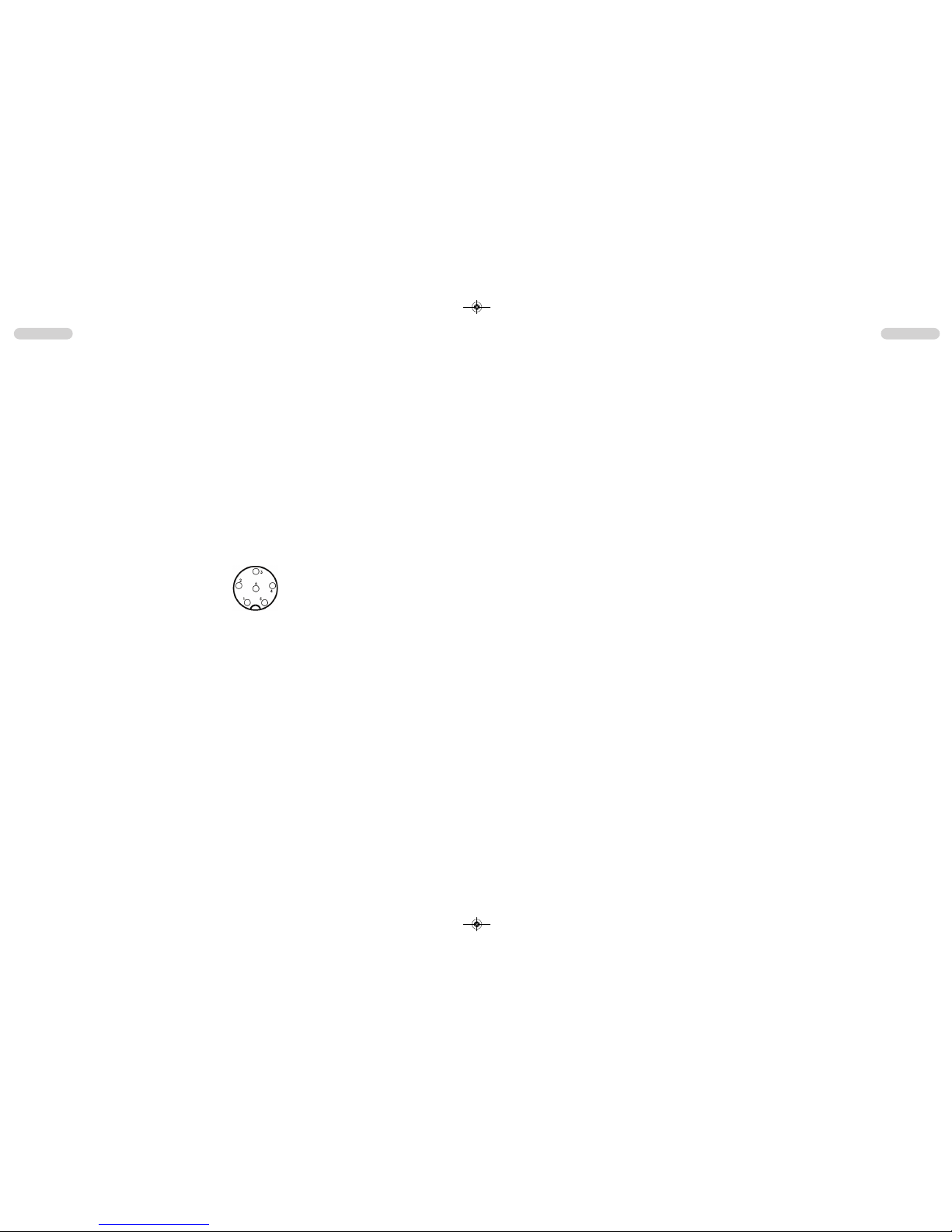
Das Mikrofon ( 1 ) wird mit dem 6poligen Stecker in die Mikrofonbuchse ( 12 ) an der linken
Gerätefrontseite angeschlossen. Ohne Mikrofon ist kein Sende- oder Empfangsbetrieb möglich. Die Mikrofonbuchse ist nach GDCH-Standard angeschlossen:
PIN 1 Modulation PIN 2 Lautsprecher
PIN 3 PTT PIN 4 Up/Down
PIN 5 Masse PIN 6 +12 Volt
5) Stromversorgung
Vor dem Anschluss der Stromversorgung schalten Sie das Gerät aus, indem Sie den Lautstärkeregler ( 10 ) [ Off / Vol ] bis zum Einrasten nach links drehen.
Verbinden Sie die beiden blanken Anschlüsse am Ende des Kabels mit dem 12 V Bordnetz Ihres Fahrzeuges. Das Stromversorgungskabel sollte möglichst weit von störenden
Aggregaten verlegt werden. Achten Sie beim Anschluss auf die richtige Polarität:
SCHWARZ wird mit "-" ( = MINUS / Masse ) des KFZ verbunden.
ROT wird mit "12 Volt +" ( = PLUS ) des KFZ/LKW-Bordnetzes verbunden.
Bei Verwendung von Dauerplus bleiben die letzten Einstellungen auch nach dem Ausschalten des Gerätes und dem Abstellen des Motors gespeichert.
Nachdem die Antenne, das Mikrofon und die Stromversorgung sorgfältig angeschlossen sind,
kann der Funkbetrieb aufgenommen werden.
Deutsch Deutsch
6 7
Ansicht von der Lötseite der
Mikrofonbuchse bzw. Vorderansicht des Mikrofonsteckers
ts-9m_manual_2:RoadCOM manual.qxd 05.09.2011 13:11 Seite 6
8) Kanalsuchlauf [ SC ]
Bei aktiver Kanalsuchlauffunktion werden alle Kanäle der eingestellten Norm nacheinander
durchsucht bis ein besetzer Kanal gefunden wird. Die Suchlauffunktion wird unterbrochen bis
das Signal endet, um dann fortzufahren.
Die Kanalsuchlauffunktion wird durch Drücken der SC-Taste (10) aktiviert bzw. deaktiviert. Im
aktiven Zustand erscheint in der Anzeige das SC Symbol (3B).
9) Anzeige AM-Sendeleistung H/L
In den meisten Normen wird auf den AM Frequenzen mit einer Sendeleistung von 1 Watt
gesendet. In diesen Fällen ist in der Anzeige (3B) der Buchstabe L (low - niedrig) zu sehen.
10) Anschlussbuchse für einen externen Zusatzlautsprecher
Das TS-9M hat an der Geräterückseite eine Klinkenbuchse (15) (3,5 mm ø) zum Anschluss
für einen externen Lautsprecher mit 4 - 8 Ohm Impedanz (z.B. TEAM TS-500). Bei Anschluss
des externen Lautsprechers wird der interne Lautsprecher abgeschaltet.
Bei 4 Ohm sollte die Belastbarkeit des Lautsprechers 4 Watt betragen.
DeutschDeutsch
8 9
Hinweis für die Norm UK:
In der Norm UK wird nur die Betriebsart FM angezeigt. Durch Drücken des AM/FM-Schalters
(7) wird zwischen den FM-Frequenzbändern EC oder UK umgeschaltet. Die Norm UK verfügt über 40 Kanäle FM UK (27,60125 - 27,99125 MHz) und 40 Kanäle FM EC (26,965 27,405 MHz).
5) Umschaltung der Normen
Die Geräteversion "TS-9M Multi Norm" kann vom Benutzer auf eine der folgenden Normen
eingestellt werden:
Norm Kanäle und Frequenzen Anzeige
DE 80 FM (26,565 - 27,405 MHz), 4 W / 40 AM (26,965 - 27,405 MHz), 1 W DE
UK 40 FM (27,60125 - 27,99125 MHz), 4 W / 40 FM (26,965 - 27,405 MHz), 4 W UK
EI 40 FM (26,965 - 27,405 MHz), 4 W / 40 AM (26,965 - 27,405 MHz), 4 W EI
EU 40 FM
(26,965 - 27,405 MHz), 4 W / 40 AM (26,965 - 27,405 MHz), 1 W EU
EC 40 FM (26,965 - 27,405 MHz), 4 W EC
PL 40 FM (26,960 - 27,400 MHz), 4 W / 40 AM (26,960 - 27,400 MHz), 4 W PL
Zum Einstellen bzw. Umschalten der Normen halten Sie bitte den Modulationarten-Umschalter ( 4 ) [ AM/FM ] während dem Einschalten des Gerätes gedrückt. In der Anzeige erscheint
das Kürzel der aktuellen Norm. Alle anderen Symbole sind nicht sichtbar. Die gewünschte
Norm wird mit Hilfe der Kanalwahltasten (4) / (5) eingestellt.
Zum Bestätigen der Norm das Gerät kurz aus- und wieder einschalten.
Für die Erlaubnis und die Auflagen zum Betrieb der verschiedenen Normen in den einzelnen Ländern sehen Sie in den Gerätepass. Der Benutzer ist für die richtige Einstellung der gültigen Norm im jeweiligen Land eigenverantwortlich.
Hinweis:
Die Ausführung TS-9M c (EC CEPT) ist fest auf 40 Kanäle FM / 4 Watt eingestellt und
somit für den Betrieb in Österreich geeignet.
6) Senden
Zum Senden wird die im Mikrofon (1) eingebaute Sendetaste (2) gedrückt und für die Dauer der
Durchsage gehalten. In dieser Zeit leuchtet das Sendekontroll-Symbol (3C) in der Anzeige.
Sprechen Sie in das Mikrofon aus ca. 5 cm Entfernung mit normaler Lautstärke. Zu lautes
oder zu leises Besprechen vermindert die Signalqualität. Nach Beendigung der Durchsage
die Sprechtaste (2) loslassen. Das Gerät schaltet automatisch in den Empfangsbetrieb
zurück.
7) Vorrangkanal 9 / 19 [ CH9/19 ]
Das Gerät verfügt über die Vorrangkanäle 9 und 19. Durch einmaliges Drücken der Vorrangkanaltaste ( 11 ) [ CH9/19 ] wird Kanal 9 eingestellt. Zum Einstellen von Kanal 19, die Vorrangkanaltaste zwei Mal Drücken.
ts-9m_manual_2:RoadCOM manual.qxd 05.09.2011 13:11 Seite 8

Deutsch Deutsch
11
HINWEISE
1) Sicherheitshinweis
Bitte beachten Sie als KFZ-Fahrer beim Funkbetrieb auch die Bestimmungen der jeweils gültigen Straßenverkehrsordnung. Bei dem Betrieb des Gerätes wird Hochfrequenzenergie freigesetzt. Es muss daher ein entsprechender Sicherheitsabstand zur Antenne eingehalten werden.
2) Allgemeine Hinweise
Das Gerät ist vor Feuchtigkeit und Staub zu schützen. Das Gerät niemals an Orten aufbewahren, die einer starken Erhitzung und/oder direkter Sonneneinstrahlung ausgesetzt sein
könnten. Zur Gehäusereinigung ein weiches, fusselfreies Tuch verwenden. Zur Reinigung
niemals Lösungsmittel verwenden.
3) Service
Das Gerät darf nicht geöffnet werden. Eigenhändige Reparaturen oder Abgleich sind nicht
vorzunehmen, denn jede Veränderung, bzw. Fremdabgleich, können zum Erlöschen der
Betriebserlaubnis sowie der Gewährleistungs- und Reparaturansprüche führen. Bei Betriebsstörungen sollte das Gerät nicht benutzt werden. Trennen Sie in diesem Fall die Stromversorgung ab. Liegt ein Defekt vor, sollte auf jeden Fall der autorisierte TEAM-Fachhändler kontaktiert werden.
4) Konformität
TEAM TS-9M
Das CB-Mobilsprechfunkgerät TEAM TS-9M entspricht der europäischen R&TTE Direktive
und hält die europäischen Normen EN 300 135-1/-2, EN 300 433-2, EN 301 489-1/-13 und
EN 60950-1 ein. Die genauen Länderbestimmungen der verschiedenen Versionen entnehmen Sie bitte dem beiliegenden Gerätepass.
5) Entsorgung
Bitte werfen Sie Ihr TEAM-Altgerät nicht einfach auf den Müll, sondern senden Sie Ihr Altgerät bitte portofrei zur fachgerechten Entsorgung an TEAM ein. TEAM wird anschließend die
umweltschonende Entsorgung Ihres Altgerätes für Sie kostenlos veranlassen. Bitte machen
Sie mit - der Umwelt zuliebe.
- Änderung der technischen Daten und der Ausführung sind ohne Vorankündigung vorbehalten. -
10
ts-9m_manual_2:RoadCOM manual.qxd 05.09.2011 13:11 Seite 10

English English
Setting up the TEAM TS-9M
1) Installation of a CB antenna
The antenna is one of the most critical parts in the setup. The type of antenna and its location has a great effect on the range of operation. Please consider the following criteria for
selection of the best location and installation of your antenna:
> Make sure that the antenna is designed for radio operation on 27 MHz.
> The location of the antenna should be as high as possible without any obstacles nearby.
> The aerial cable should not be damaged and the plugs should be properly connected.
> Make sure that the antenna cable is not bent.
When you install a mobile antenna please note the following advices:
> The antenna should be fixed in the center of a big body-part, e.g. the trunk.
> The mobile antenna coil should have the closest possible contact with a conducting metallic
surface of the bodywork of the car.
There are also some other possibilities to fix the antenna onto the car without the necessity
to drill a hole into the bodywork of your car, e.g. mounting the antenna onto the gutter, mounting the antenna onto a holder on the cover of the boot or using an antenna with a magnetic
foot or using a windscreen antenna.
2) Aerial Connection
Before pressing the transmit key, a suitable aerial must be connected. The PL259 plug of the
aerial cable ( coax ) is connected to the SO239 socket ( 13 ) on the rear panel. Make sure,
that all plugs are firmly tightened and properly soldered. Insufficient connections can damage
the radio and will reduce the range of operation.
The antenna should be matched with the radio, otherwise a part of the transmit power will be
reflected at the antenna and will not be radiated. This reduces the range of operation. The
matching of antenna to radio, is performed by a length adjustment of the antenna radial in
aim for a minimal SWR ratio which can be measured by a SWR meter,e.g. TEAM SWR
1180P. After the measurement the SWR meter should be removed from the antenna line.
3) Installation in the car
When you want to fix the unit in your car, you can either fasten it with the help of the included
mounting bracket below the dashboard. Always mount the transceiver where the switches are
easily accessible. Other important points to consider for a correct mounting position are:
> no interference of the roadworthiness,
> good access to the controls of the car,
> sufficient air circulation to prevent overheating of the radio in transmit mode.
Please consider the angle of view onto the display while driving. From a certain angle of view,
the readability of the display diminishes. An intensive solar irradiation can also affect the readability of the display. So it is recommended to check the best position before the final installation. The unit can easily be fixed onto different positions in the car by using the enclosed
mounting bracket.
TABLE OF CONTENTS
Setting up the TEAM TS-9M
1) Installation of a CB antenna 13
2) Aerial Connection 13
3) Installation in the car 13
4) Microphone 14
5) Power source 14
Operation of the TEAM TS-9M
1) Switching on [ Off / Vol ] 15
2) Squelch [ SQ / ASQ ] 15
3) Channel selection [ q ] [ p ]15
4) Modulation selection [ AM/FM ]15
5) Norm selection 16
6) Transmitting 16
7) Priotitiy Channels 9 / 19 16
8) Channel Scan 16
9) AM Transmission Power 17
10) External speaker jack 17
Additional Information
1) Safety Instructions 17
2) General Precautions 17
3) Servicing 17
4) Conformity 17
Channel Frequencies 18
Specifications 19
Schematic Diagram & PCB layout 20 - 23
12 13
ts-9m_manual_2:RoadCOM manual.qxd 05.09.2011 13:11 Seite 12
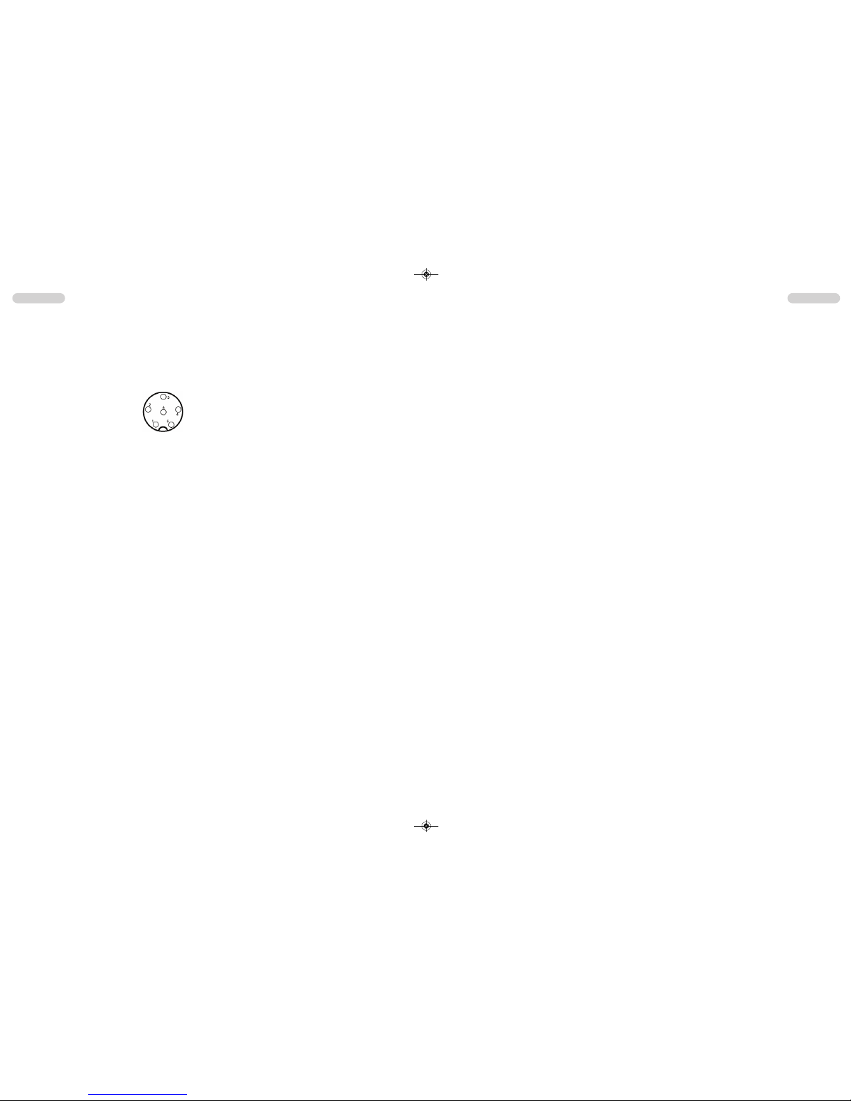
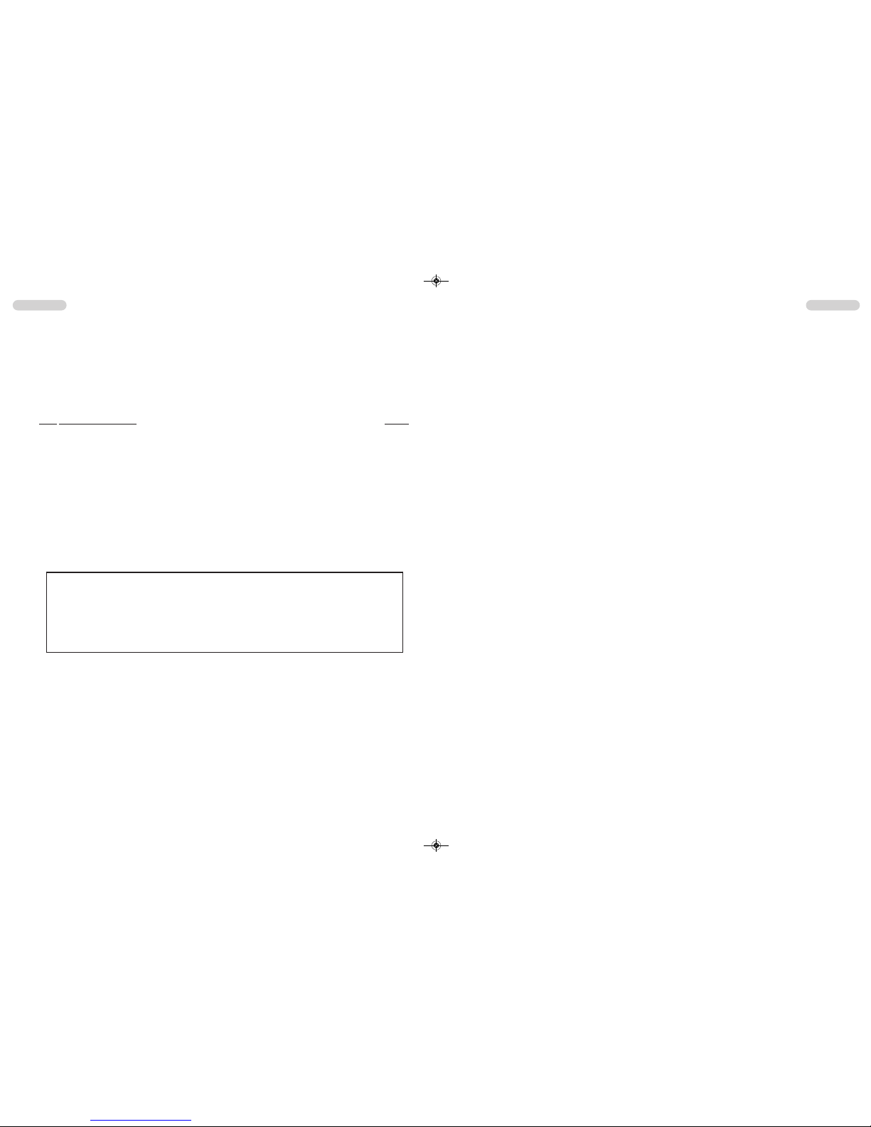
4) Microphone
Plug the microphone ( 1 ) into the 6 pin socket ( 12 ) on the front panel. Note it will only go in
one way round. No transmission and receiving is possible without the microphone. The pin
assignment of the GDCH standard microphone plug is given below:
PIN 1 Modulation
PIN 2 Loudspeaker
PIN 3 PTT
PIN 4 Up/Down
PIN 5 Ground
PIN 6 +12 Volt
Solder side view of the microphone connector or top view of the microphone plug.
5) Power source
Before connecting the unit to a suitable power source via the fused DC power cable (15), the
device must be switched off by turning the volume control ( 9 ) [ Off / Vol ] counterclockwise
to the very end until a clicking sound is heard.
Then, connect the two naked leads at the end of the cable with the supply voltage of the
car/lorry battery. The unit is designed to operate with 12 volts and a negative ground electrical system. Lay the cable as far as possible away from aggregates which can cause interference. Watch for the correct polarity during the connection.
BLACK connect to - MINUS / ground of the car battery.
RED connect to 12 volts + PLUS of the car/lorry battery.
If the power source is not disconnected after putting the engine off, the last settings will
remain stored, after the unit and the car are switched off.
After proper connection of the microphone, the aerial and power source, radio operation can
be started.
Operation of the TEAM TS-9M
1) Switching on [ Off / Vol ]
To turn on the radio, turn the On / Off switch (10) [ Off / Vol ] clockwise.
With the help of the squelch control (8) you can set a comfortable volume level. Set the manual squelch (SQ) to a level where the constant noise of an empty channel is audible - see paragraph 2) Squelch. Now, adjust the volume level.
The memory function stores the last settings, i.e. norm, frequency band and channel after turning the radio off and on again.
2) Squelch [ SQ / ASQ ]
The strong background noise, which occurs always on free channels, can be suppressed by
the squelch function, which has an automatic and a manual mode.
By turning the squelch control (8) slowly clockwise you will find a point where the noise disappears. The squelch control should only be turned up far enough to stop the background
noise on an unused channel. Turning the control further clock-wise will increasingly suppress
stronger interfering signals as well as weak stations.
The automatic squelch [ ASQ ] (7) uses a preset average value. This function is turned on/off
by pressing the ASQ key (7). The automatic squelch mode is indicated by the AQ symbol (6F)
in the LCD.
3) Channel selection [ q ] [ p ]
All channels can be selected by pushing the channel selector keys (5) [ qCH ] and (6) [ pCH ]
located on the front panel of the radio. The selected channel is displayed on the LCD (3). No
channel selection is possible while the radio is in transmission mode. The channels are
arranged in a consecutive order, in a ring-like-system, i.e. after the highest channel number it
starts again with channel no. 1 and vice versa. For communication with a partner CB station,
both transceivers must be adjusted to the same channel and the same modulation type.
4) Modulation selection [ AM/FM ]
For the TS-9M, the operating modes AM and FM are available. However, the version TS-9M c
(EC CEPT) and the norm EC of the the version TS-9M Full Multi Norm operate in FM only.
The selected modulation type is indicated by the AM/FM symbol (3E). To toggle between the
modes press the mode key (4) [ AM/FM ].
If the selected norm does not accept the modulation type AM on the actual channel, it will
remain on the modulation type FM.
If the radio is set to AM on the actual channel, and you select another channel, on which the
AM mode is inhibited, the modulation changes automatically to FM mode. If you select once
more another channel, on which the AM mode is allowed again, the modulation switches automatically to back to AM mode.
With norm UK in the version TS-9M Full Multi Norm, you toggle between the EC band and
the UK band, which are indicated by the symbols EC and UK, by pressing the mode key (7)
[ AM/FM ]. The CB band EU consists of the 40 CEPT channels. The CB band UK consists of
40 channels starting from 27.60125 MHz to 27.99125 MHz.
After turning the radio off, the TS-9M stores the last channel and the frequency band.
English English
14 15
ts-9m_manual_2:RoadCOM manual.qxd 05.09.2011 13:11 Seite 14
 Loading...