

Team TMN-51T Hardware User's Manual

1
TMN-51T
Hardware User Guide
Copyright 2007, TCAM Technology Pte Ltd. All Rights Reserved.
This document (TMN-51T Hardware User Guide) contains information that is proprietary
to TCAM Technology Pte Ltd. No part of this document may be copied, or reproduced in
any form or by any means, or transferred to any third party without prior written consent
of TCAM Technology Pte Ltd. The content of this document may be revised without
prior notice.
TMN-51T Hardware User Guide

2
Specification
Details
Transmission
GPRS
GPRS Connectivity
GPRS multi-slot class 10
GPRS mobile station class B
Frequency Band
Dual Band EGSM900 and GSM1800
Quad band E-GSM 850/900Mhz and GSM
1800/1900Mhz
Transmit Power
Class 4 (2W) for E-GSM 850, E-GSM 900
Class 1 (1W) for GSM 1800, GSM 1900
RF Power
E-GSM 850, E-GSM 900: 33dBm
GSM 1800, GSM 1900: 30dBm
External Antenna
Connected via antenna SMA connector
Serial Interface
DB9 Female Connector, RS232 standard
o RS485 is optional
Supporting 300, 1200, 2400, 4800, 9600, 19200,
38400, 57600, 115200 bps and Auto Baud Rate
Power Supply Interface
4 pin Micro Fit 3.0
Supply voltage
6-40VDC
Supply current
0.08A at 12VDC (GPRS online, no data)
0.2A at 12VDC (Data transmission)
Dimensions
86 x 54 x 25mm
Weight
110g
Temperature
0 to 55°C (normal)
-20 to +70°C (restricted)
Analog inputs
Support 2 channels each capable of measuring
4-20mA analog signal.
TMN-51T Specifications
System Overview
TMN-51T is a plug and play RS232 to GPRS gateway. It can easily retrofit a traditional
serial communication system to a more advance GPRS platform. Remote devices can be
centrally managed without upgrading the device firmware and central software. Unlike
those systems that the devices are centrally managed via PSTN or GSM dial up line or
lease line, TMN-51T can be a more cost economical solution to achieve an “always on”
data link network.
Note: TMN-51T may be able to use with 3G SIM card/data plan seamlessly but subjected
to Telco‟s offering.
Hence, our customers may enjoy the economical 3G data plan for higher data bandwidth
package.
TMN-51T Hardware User Guide
3
RTOS
RTC
IAP
UART0
UART1
AM
EM
NV
Debug
GPRS
Modem APP
SMS APP
Service Layer
Application Layer
Kernel Layer
GPRS APP
Control APP
Call APP
Main APP
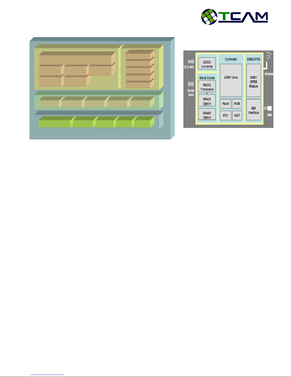
Firmware Block Diagram
Hardware Block Diagram
Key Features
Plug and Play • Full Transparent Data Transmission
• Protocol independent
Rich Options • UDP for fast and bulk data transfer
• TCP for reliable data transfer
• App control protocol for secure data transfer
Robust Operation • Self test
• Self reset and recovery
• Data buffering
• Support auxiliary data center
Easy Control • Remote configuration by SMS or GPRS
• Remote activation by SMS or Data Call
Always ON Connection • Heart beat feature for socket connection
• Time to live timer for network checking
Flexible Operation • 3 methods of serial data packetization
• Server mode and client mode for connection
• Static or dynamic IP
• Support RS232 / 485 hardware interface
TMN-51T Hardware User Guide
4
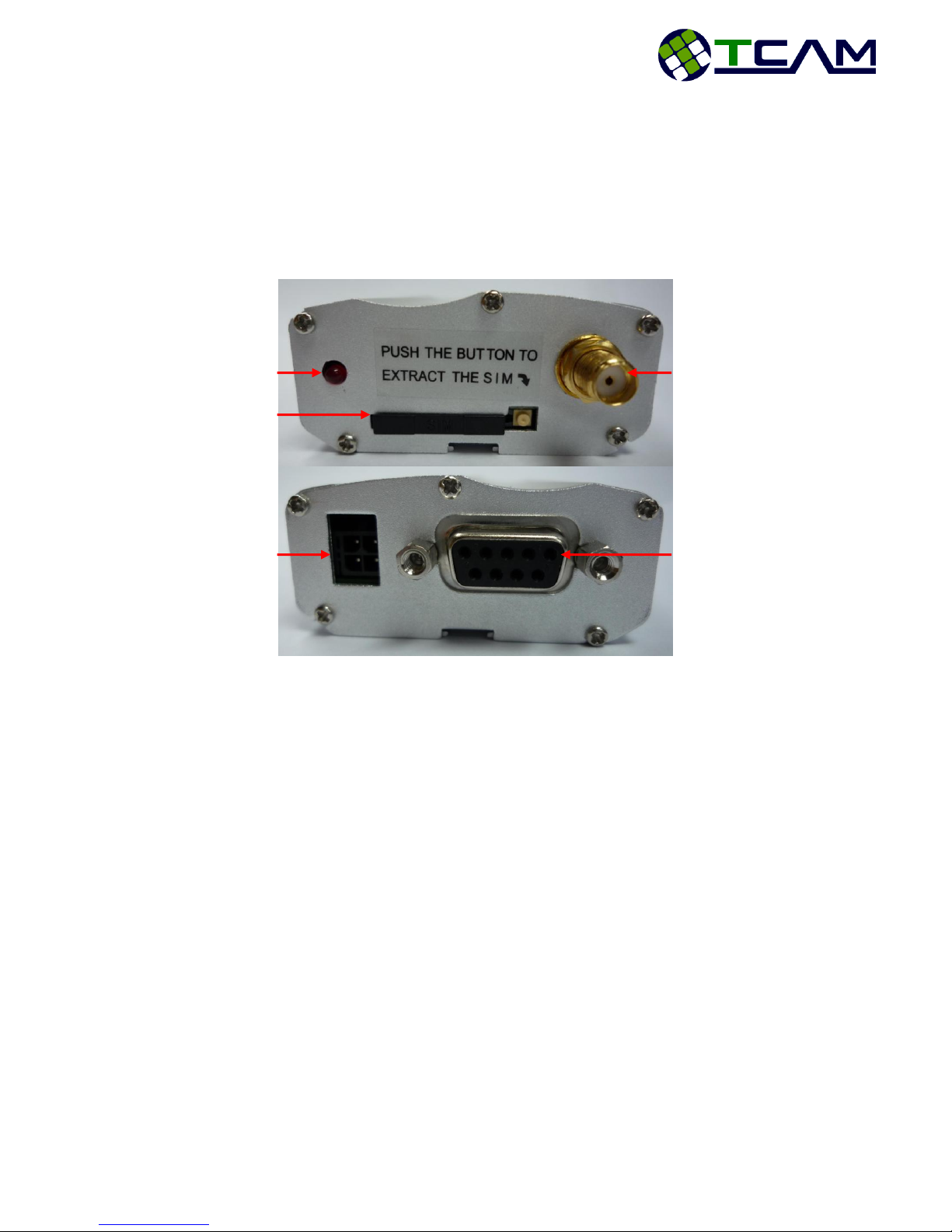
DB9 Connector
4 Pin Micro Fit 3.0
Connector
SIM Card Holder
Red LED
Radio Interface
TMN-51T Interface
TMN-51T contains the following interfaces as shown in Figure 1:
SIM Card Holder
SMA connector for antenna (radio interface)
DB9 Female Connector
4 pin power supply socket
Figure 1: TMN-51T Interface
DB9 Female Connector
Main interface: DB9 female connector
Communication standard:
RS232 (default)
RS485 (optional)
Figure 2 shows the DB9 female interface for TMN-51T including all the pin numbers.
TMN-51T Hardware User Guide
5
Pin
RS232
RS485
Description
1 - -
2
Receive
-
3
Transmit
- 4 -
-
5
Ground
-
6
-
Data +
7
RTS
-
8
CTS
-
9
-
Data -
5 4 3 2 1
9 8 7 6
1 2
3 4
Figure 2: DB9 Female Interface
Listed below are the pin configurations of DB9 connector for all 2 communication
standards.
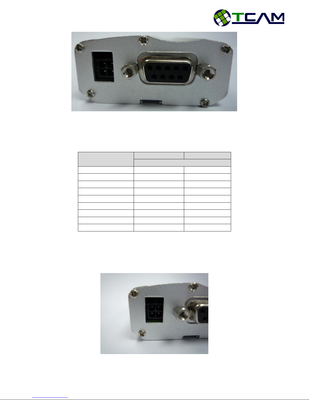
Micro Fit 3.0 Power Supply Connector
Shown in Figure 3 is the 4-pin Micro Fit 3.0 power supply socket for TMN-51T.
Included in the figure is the pin numbering for the socket.
TMN-51T Hardware User Guide
Figure 3: Micro Fit 3.0 Power Supply Socket for TMN-51T
 Loading...