

Page 1
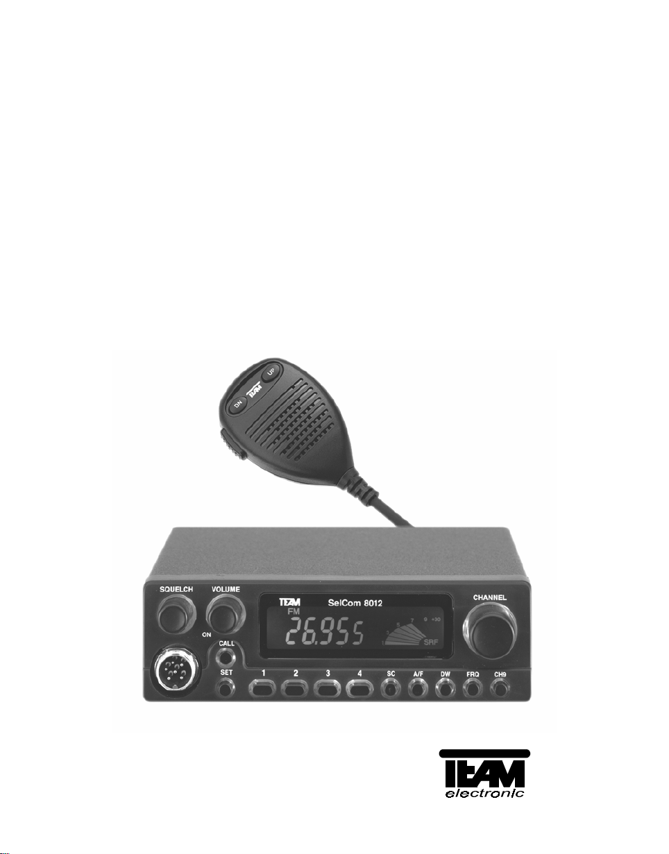
SelCom 8012
SelCom 4040
Bedienungsanleitung
Operating instructions
Mode d’emploi
Manuale di istruzioni
Page 2

Inhalt, Contents, Contenu, Contenuto Seite, Page, Page, Pagina
Bedienelemente 3 / 4
Controls 3 / 12
Eléments de commande 3 / 26
Comandi 3 / 33
Bedienungsanleitung 5 - 11
Operating instructions 13 - 18
Mode d’emploi 27 - 32
Manuale di istruzioni 33 - 39
Bestückungspläne und Platinenlayouts /
Components locations and PCB Layouts 19 - 21
Schaltplan / Schematic Diagram /
Schéma de principe / Schema elettrico ( Main PCB ) 22 - 23
Schaltplan / Schematic Diagram /
Schéma de principe / Schema elettrico ( Front PCB ) 24
Blockschaltbild / Block Diagram 25
Technische Daten / Technical Data / SelCom 8012 40
Technische Daten / Technical Data / SelCom 4040 41
Ersatzteile / Spare parts 42 - 43
- 2 -
Page 3
TEAM SelCom 8012 / SelCom 4040
1
2
3
4
SQUELCH
5
VOLUME
ON
6
CALL
SET
7
14
18
CHANNEL
CH9
16
15
19
DC 13.8V
Se lCom 8012TEAM
1
8
3
2
10
9
SC A/FDWFRQ
4
12
11
13
17
ANT
EXT SP
- 3 -
EXT SMETER
20
Page 4

TEAM SelCom 4040
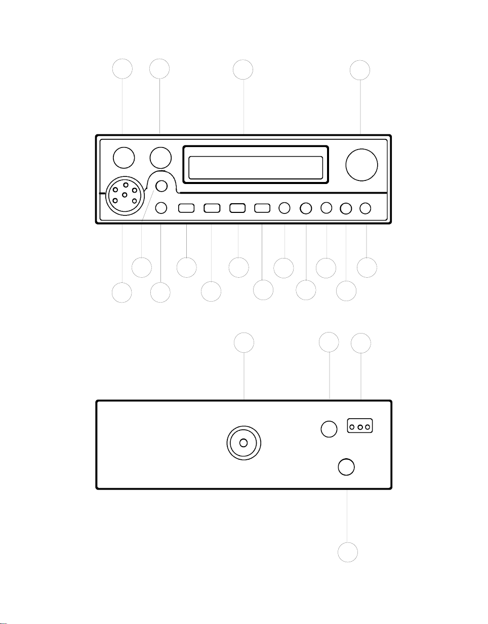
OPERATION CONTROLS, DISPLAYS AND CONNECTORS
( 1 )
( 2 )
( 3 )
Squelch control
Volume control / ON switch
LCD display window for channel number, frequency, functions and
[ SQUELCH ]
[ VOLUME / ON ]
S-meter
( 4 )
( 5 )
Rotary switch for channel selection
Microphone connector 6 pin for any microphone with or without
[ CHANNEL ]
UP/DOWN channel selection and amplifier
( 6 )
Call and encoding button for transmitting of the DTMF selective call
( 7 )
( 8 )
( 9 )
( 10 )
( 11 )
( 12 )
[ CALL ]
Standby and encoding button for receiving of the DTMF selective call
[ SET ]
Channel memory
Channel memory
Channel memory
Channel memory
Button for occupied channel search function ( SCAN )
[ 1 ]
and encoding button for DTMF dual tone No. 1.
[ 2 ]
and encoding button for DTMF dual tone No. 2.
[ 3 ]
and encoding button for DTMF dual tone No. 3.
[ 4 ]
and encoding button for DTMF dual tone No. 4.
[ SC ]
( 13 )
Toggle switch button for AM or FM mode
( 14 )
Button for dual watch function
( 15 )
Toggle switch button for channel or frequency display
( 16 )
Priority channel selector button
( 17 )
Antenna connector SO239
( 18 )
Socket for external speaker 3.5 mm
( 19 )
Connector for DC supply cord ( 3 pin )
( 20 )
Socket for external S-meter 2.5 mm
[ DW ]
[ CH9 ]
[ ANT ]
[ EXT S-METER ]
[ A/F ]
[ EXT SP ]
[ DC 13.8V ]
- 12 -
[ FRQ ]
Page 5

wise and adjust it to a comfortable listening level. If the transceiver is on a clear
channel and not muted by the squelch function a noise should be heard from the
speaker now. The back illumination of the display ( 3 ) and the front panel will
light up. When the unit is switched on the first time or after being disconnected
for a longer period the first channel will be channel 9 in FM mode. The display
will show [ 9, FM and SRF ]. If the power source is not disconnected after
switching off, the settings and functions will be stored ( memory backup ). All correct entries will be confirmed by a receipt tone.
2. Squelch function [ SQUELCH ] :
Rotate the squelch control ( 1 ) [ SQUELCH ] slowly clockwise until the background noise just disappears while any incoming signal will be heard. The
squelch control should only be turned up enough to stop the background noise
on an unused channel. Turning the control further clockwise will increasingly
suppress interfering signals as well as weak stations. The setting should be
made on an unused channel.
3. Channel selection [ CHANNEL ] :
Select the desired channel 1 - 40 with the channel selector switch ( 4 )
[ CHANNEL ]. The display ( 3 ) shows the actual channel. The CH9 function
must not be activated which will be indicated by a flashing 9 in the display. In
parallel the channels can be controlled by the built-in UP/DOWN buttons of the
microphone. The channel numbers step in a ring like system UP from 40 to 1
and DOWN from 1 to 40.
It is also possible to show the actual frequency ( in MHz ) in the display instead
of the channel numbers by pressing the button ( 15 ) [ FRQ ]. This has no influence on the following described functions. By pressing the button ( 15 ) [ FRQ ]
a second time the channel number will appear in the display again.
Radio operation is only possible with the counter station at coinciding channel
numbers and modulations. By pressing the instant channel key ( 16 ) [ CH9 ]
channel 9 can be selected for transmit and receive immediately. A flashing 9 will
appear in the display. No channel selection is possible now. Pressing ( 16 )
[ CH9 ] again will cancel this function and the unit returns to the previous selected channel.
4. Modulation selection [ A/F ] :
By pushing the key ( 13 ) [ A/F ] the transceiver will toggle between AM and FM
mode. The actual modulation type is indicated by the symbols [ FM, AM ] in the
display ( 3 ).
With the TEAM SelCom 4040 all 40 channels can be selected both in AM and
in FM mode. In FM mode the transmit output power is 4 W and in AM mode it is
1 W.
- 13 -
Page 6

wise and adjust it to a comfortable listening level. If the transceiver is on a clear
channel and not muted by the squelch function a noise should be heard from the
speaker now. The back illumination of the display ( 3 ) and the front panel will
light up. When the unit is switched on the first time or after being disconnected
for a longer period the first channel will be channel 9 in FM mode. The display
will show [ 9, FM and SRF ]. If the power source is not disconnected after
switching off, the settings and functions will be stored ( memory backup ). All correct entries will be confirmed by a receipt tone.
2. Squelch function [ SQUELCH ] :
Rotate the squelch control ( 1 ) [ SQUELCH ] slowly clockwise until the background noise just disappears while any incoming signal will be heard. The
squelch control should only be turned up enough to stop the background noise
on an unused channel. Turning the control further clockwise will increasingly
suppress interfering signals as well as weak stations. The setting should be
made on an unused channel.
3. Channel selection [ CHANNEL ] :
Select the desired channel 1 - 40 with the channel selector switch ( 4 )
[ CHANNEL ]. The display ( 3 ) shows the actual channel. The CH9 function
must not be activated which will be indicated by a flashing 9 in the display. In
parallel the channels can be controlled by the built-in UP/DOWN buttons of the
microphone. The channel numbers step in a ring like system UP from 40 to 1
and DOWN from 1 to 40.
It is also possible to show the actual frequency ( in MHz ) in the display instead
of the channel numbers by pressing the button ( 15 ) [ FRQ ]. This has no influence on the following described functions. By pressing the button ( 15 ) [ FRQ ]
a second time the channel number will appear in the display again.
Radio operation is only possible with the counter station at coinciding channel
numbers and modulations. By pressing the instant channel key ( 16 ) [ CH9 ]
channel 9 can be selected for transmit and receive immediately. A flashing 9 will
appear in the display. No channel selection is possible now. Pressing ( 16 )
[ CH9 ] again will cancel this function and the unit returns to the previous selected channel.
4. Modulation selection [ A/F ] :
By pushing the key ( 13 ) [ A/F ] the transceiver will toggle between AM and FM
mode. The actual modulation type is indicated by the symbols [ FM, AM ] in the
display ( 3 ).
With the TEAM SelCom 4040 all 40 channels can be selected both in AM and
in FM mode. In FM mode the transmit output power is 4 W and in AM mode it is
1 W.
- 14 -
Page 7

5. Occupied channel search ( SCAN ) [ SC ] :
Before selecting the SCAN function set the squelch control ( 1 ) [ SQUELCH ]
according to Para 2 of this chapter because this function does not work with unmuted receiver. Depress the key ( 12 ) [ SC ] now. In the display appears [ SC ]
and the channels are stepping upwards. SCAN stops on the first occupied channel, where a signal can trigger the squelch threshold. It continues 10 seconds after the signal falls below the squelch threshold.
Depressing the key ( 12 ) [ SC ] again or any other, except ( 15 ) [ FRQ ], will
stop the SCAN function.
6. Dual Watch [ DW ] :
This function allows to watch activity on a second channel. Before selecting the
DW function set the squelch control ( 1 ) [ SQUELCH ] according to Para 2. Select now the first channel which you want to survey and then depress briefly the
button ( 14 ) [ DW ]. In the display appears a flashing [ DW ] sign. Start within 5
seconds selecting the second channel which you want to survey otherwise the
DW function will stop automatically. After having reached the desired channel
press the button ( 14 ) [ DW ] another time and the symbol [ DW ] will appear
permanently. Now the DW function is completely activated.
The DW function will remain on this channel if the incoming signal can open the
squelch and is not longer interrupted than 10 seconds. Otherwise the unit will
tune to the other channel. If no signal is found there the radio will step every
second to the other channel.
Depressing the key ( 14 ) [ DW ] again or any other, except ( 15 ) [ FRQ ], will
stop the DW function.
7. Transmit ( Push To Talk / PTT ) :
To transmit depress and hold the PTT key on the microphone. In the display appears [ TX ] and together with the symbol [ SRF ] = ( Signal Radio Frequency )
the relative output power will be shown in form of a progressively increasing
number of bar sections. The microphone sensitivity has been set to give good
results speaking normally at a distance of 2 - 4 inches. Speaking too loudly will
cause distortion and make the signal difficult to understand especially in case of
amplifier or echo microphones. While the set is in the transmitting mode there is
no key entry possible and the receiver is muted. On completion of the transmission release the PTT key and the set will revert to receiving mode.
8. S-meter [ EXT S-METER ] :
Behind the letters [ SRF ] the relative transmit power and received fieldstrength
will be displayed in the window ( 3 ), forming progressive bar sections. The
TEAM SelCom 4040 has on its rear panel a socket ( 20 ) EXT S-METER for the
connection of an additional S-meter with a 2.5 mm plug.
- 15 -
Page 8

9. External speaker [ EXT SP ] :
The TEAM SelCom 4040 has on its rear panel a socket ( 18 ) [ EXT SP ] for an
external speaker of 4 - 8 ohm impedance with 3.5 mm plug. At 4 ohms the dissipation of the speaker can be up to 2 watts.
10. Channel memory keys [ 1 - 4 ] :
The TEAM SelCom 4040 can store up to 4 frequently used channels and their
modulations. The default settings of the memories 1 - 4 are the channels 1, 9,
19, 40. These memories can be overwritten with other channel numbers. In case
of data loss the default settings will be stored in the memories again.
To save a new channel first select it with the channel selector switch ( 4 )
[ CHANNEL ]. Then depress one of the memory keys ( 8 - 11 ) [ 1 - 4 ] for 4 or 5
seconds until a second receipt tone indicates the overwriting of the new channel
number into the corresponding memory.
To call a saved channel depress briefly the corresponding memory key. On the
left side of the display the actual memory number is displayed in case of data
storage or recall. The memory number disappears by selecting a new channel.
11. DTMF Selective Call System [ CALL / SET ] :
General :
The DTMF selective call system ( = Dual Tone Modulation Frequency ) enables
the radio operator to open one or more muted receiver by transmitting a specially
coded tone sequence. This is only possible on condition that all partners use the
same channel, modulation mode and selective call system. The transceivers
must be switched on and operate normally and the selective call system has to
be set into standby mode to receive the coded tone calls. This will mute the
loudspeaker of the receiver until the detection of a coded tone sequence, which
corresponds with the own reception code of the transceiver. This will open the
receiver and it will remain unmuted even when the calling station stops transmitting. So all activities on this channel can be heard, and those stations which are
not equipped with a selective call system, too. It is also possible to communicate
with them. They are only unable to open a receiver muted by a selective call system.
The TEAM SelCom 4040 selective call system uses 4 dual tones in succession.
There are 4 different dual tones. So there are 256 combinations possible. The
reception code and the transmission code can be programmed separately from
each other. For individual call it is recommended for each participant to program
his own reception code. Example : 4 Partners, consisting of head office and 3
mobile stations: Head office = 1111 / Jack mobile = 1112 / Susan mobile = 1113
/ John mobile = 1114. In case of group call all members have the same reception
code. This will open all receivers if the transmitted code is sent out interferencefree and free of noise. In all cases the transmission code of the
- 16 -
Page 9

calling station and the reception code of the listening station have to match. In
our example the head office has to change its transmission code to reach every
participant in case of individual call. The same applies to the mobile stations if
they want to reach each other. If the communication is made with the help of the
head office all mobile stations need only the transmission code 1111.
Entry of the reception code :
Depress briefly the button ( 7 ) [ SET ] so that the symbol “music note“ appears
in the display on the top right of the channel number. The receiver is now muted.
Depress the key ( 7 ) [ SET ] again but hold it for 3 or 4 seconds until a second
receipt tone indicates that the radio is ready for data input. The display shows
now [ 0000 ] with a flashing first digit. Begin now entering within 3 - 4 seconds
the reception code with the keys ( 8 - 11 ) [ 1 - 4 ]. With every new entry the
flashing digit moves one step further to the right. After entering the last digit the
inputs will be saved 3 - 4 seconds later automatically and the display will revert
to the normal mode. The same procedure applies when you overwrite previous
entries.
Entry of the transmission code :
Depress briefly the button ( 7 ) [ SET ] so that the symbol “music note“ appears
in the display. Then depress the key ( 6 ) [ CALL ] and hold it for 3 or 4 seconds
until a second receipt tone indicates the readiness for data input. The display
shows again [ 0000 ] with a flashing first digit. Begin now entering within 3 - 4
seconds the transmission code with the keys ( 8 - 11 ) [ 1 - 4 ]. With every new
entry the flashing digit moves one step further to the right. After entering the last
digit the inputs will be saved 3 - 4 seconds later automatically and the display will
revert to the normal mode. The same procedure applies when you overwrite previous entries.
Radio operation with the DTMF selective call system :
To activate the DTMF selective call system depress briefly the button ( 7 )
[ SET ] so that the symbol “music note“ appears in the display. This will mute the
receiver and make it ready to decode received selective tone calls on the actual
channel. In case of a previous sent out transmission code or recognition of a selective tone call the receiver will be opened. The symbol “music note“ will remain
in the display instead. If you want to make it silent again you have to cancel the
DTMF function ( “music note“ disappears ) and to reactivate it again by pressing
the button ( 7 ) [ SET ] two times.
A transmission of a selective tone call is only possible with the activated DTMF
function ( symbol “music note“ ) in the display. To start the transmission depress
the button ( 6 ) [ CALL ] briefly. The radio will switch over to transmission mode
and starts sending out the transmission code. When the tone sequence is sent
out completely it will revert to not muted receiving mode. If the channel is clear
- 17 -
Page 10

and the counter station within the range its receiver will be opened, too. The
communication can begin now. DTMF operation is possible in both types of
modulation. We recommend the use of FM because of the better safety against
disturbance.
12. Battery backup :
As long as the TEAM SelCom 4040 is connected without any interruption to a
car battery or a switched on power supply the memory contents of selective call
codes and channels will be kept stored, even when it is switched off at ( 2 )
[ VOLUME / ON ]. In addition it contains an built-in rechargeable button cell
which will only be charged when the unit is in operation. According to the periods
of running and the periods of not working the charging condition may be quite
different. So it is recommended to keep an eye on a reasonable charging time
before writing to the memories. A completely charged battery can keep the
memory contents stored for up to 100 hours even when the unit is disconnected
from every power source.
13. Servicing the TEAM SelCom 4040 :
There are no user adjustable or user serviceable parts inside the radio. The casing must not be opened. Independent repairs or adjustments must not be carried
out, since each modification or unauthorised intervention will immediately cancel
all and any guarantee or repair claims, they are also likely to result in nonconformity to approval regulations which will render the set illegal. In the event of a
defect becoming apparent, contact a properly equipped and authorised dealer.
- 18 -
Page 11

TECHNISCHE DATEN / TECHNICAL DATA
TEAM SelCom 8012
Kanalnummern und Frequenzen nach BAPT 222 ZV 102 / 104 ( 80 Kanäle )
Kanal Nr.- Frequenz
Channel Nbr. - Frequency
01 26.965 MHz FM 21 27.215 MHz FM 41 26.565 MHz FM 61 26.765 MHz FM
02 26.975 MHz FM 22 27.225 MHz FM 42 26.575 MHz FM 62 26.775 MHz FM
03 26.985 MHz FM 23 27.255 MHz FM 43 26.585 MHz FM 63 26.785 MHz FM
04 27.005 MHz FM/AM 24 27.235 MHz FM 44 26.595 MHz FM 64 26.795 MHz FM
05 27.015 MHz FM/AM 25 27.245 MHz FM 45 26.605 MHz FM 65 26.805 MHz FM
06 27.025 MHz FM/AM 26 27.265 MHz FM 46 26.615 MHz FM 66 26.815 MHz FM
07 27.035 MHz FM/AM 27 27.275 MHz FM 47 26.625 MHz FM 67 26.825 MHz FM
08 27.055 MHz FM/AM 28 27.285 MHz FM 48 26.635 MHz FM 68 26.835 MHz FM
09 27.065 MHz FM/AM 29 27.295 MHz FM 49 26.645 MHz FM 69 26.845 MHz FM
10 27.075 MHz FM/AM 30 27.305 MHz FM 50 26.655 MHz FM 70 26.855 MHz FM
11 27.085 MHz FM/AM 31 27.315 MHz FM 51 26.665 MHz FM 71 26.865 MHz FM
12 27.105 MHz FM/AM 32 27.325 MHz FM 52 26.675 MHz FM 72 26.875 MHz FM
13 27.115 MHz FM/AM 33 27.335 MHz FM 53 26.685 MHz FM 73 26.885 MHz FM
14 27.125 MHz FM/AM 34 27.345 MHz FM 54 26.695 MHz FM 74 26.895 MHz FM
15 27.135 MHz FM/AM 35 27.355 MHz FM 55 26.705 MHz FM 75 26.905 MHz FM
16 27.155 MHz FM 36 27.365 MHz FM 56 26.715 MHz FM 76 26.915 MHz FM
17 27.165 MHz FM 37 27.375 MHz FM 57 26.725 MHz FM 77 26.925 MHz FM
18 27.175 MHz FM 38 27.385 MHz FM 58 26.735 MHz FM 78 26.935 MHz FM
19 27.185 MHz FM 39 27.395 MHz FM 59 26.745 MHz FM 79 26.945 MHz FM
20 27.205 MHz FM 40 27.405 MHz FM 60 26.755 MHz FM 80 26.955 MHz FM
Betriebsspannung / Supply Voltage 13.2 Volt nominal ( 11 - 15 Volt Betrieb / operating )
Stromaufnahme
Current Consumption
Gewicht, Weight ca. 750 gr. ohne Zubehör und Verpackung
Maße, Dimensions B 158, T 135, H 48 mm ( Gehäuse / Cabinet )
Empfindlichkeit / Sensitivity 1.2 µV / 1.2 KHz Hub / Deviation. 20 dB (S+N+D)/N
Zwischenfrequenz
Intermediate Frequency
Selektivität,/ Adjacent Channel Rejection => 60 dB / ETS 300 135
Intermodulationsdämpfung
Intermodulation Response Rejection
NF - Ausgangsleistung / Audio Output Power 2.0 Watt / 8 Ohm ( 10% THD )
Sendeleistung
RF Output Power
Modulationshub ( FM ) Modulation Deviation
Modulationsgrad ( AM ) Modulation Degree
Betriebsart / Type of Emission
Oberwellenunterdrückung / Harmonics Rejection
Nebenwellenunterdrückung / Spurious Rejection
Kanal Nr. - Frequenz
Channel Nbr.- Frequency
Allgemein / General
RX - Empfänger / Receiver
TX - Sender / Transmitter
- 40 -
Kanal Nr. - Frequenz
Channel Nbr. -
Frequency
RX = 490 mA ( inklusive Nachtlicht )
TX = 1370 mA ( FM ) inklusive Nachtlicht
820 mA ( AM ) “ “
1. ZF 10.695 MHz
2. ZF 455 KHz
=> 54 dB / ETS 300 135
4.0 Watt / 50 Ohm ( FM )
1.0 Watt / 50 Ohm ( AM )
2 KHz max. ( begrenzt )
90% max. ( begrenzt )
F3E ( Frequenzmodulation / Frequency Modulation )
A3E ( Amplitudenmodulation / Amplitude Modulation )
<= 4 x 10
<= 2.5 x 10
-9
-7
Kanal Nr. - Frequenz
Channel Nbr. -
Frequency
W
W
 Loading...