

Page 1
Discovery
From the Makers of
TTG-631
10 +
ASSEMBLY & INSTRUCTION MANUAL
Page 2

CONTENTS
Introduction
Tools You May Need
Mechanical Parts List
Plastic Parts
TIP: Cut off Burrs
Cut and Fit Air Tubes
Tube Module Assembly
P.1
P.1
P.1
P.3
P.4
P.4
P.5
Testing Air Leaks
Vehicle Body Module Assembly
How To Play
Trouble Shooting
P.13
P.17
P.42
P.43
Page 3
I n t r o d u c t i o n
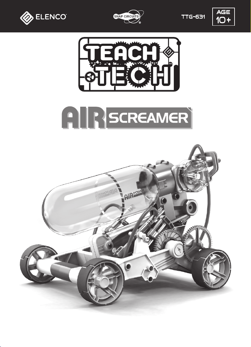
This am azi ng vehicle is f ast and f u riou s- - and p owered by AI R !
W atch and learn as com p resse d air exp lodes ou t of the tank to ru n a p neu m atic m otor p owering gears
and m oving you r vehicle. C om p resse d air vehicles have been in the works f or years with f u nctional
locom otives in the 187 0' s and cars in early 20th centu ry. This is the technology behind the f antast ic
vehicle that is the Air Scream er. Pu m p u p the volu m e …. .. of air. F ill the tank one crank at a tim e.
The crank is bu ilt into the Air Scream er' s body. Saf ety valves are in p lace that bleed of f over p u m p ed air
and elim inate the p ossi bility of disa st er. I f you crank too m u ch, the sa f ety valve lets ou t air u ntil the tank
reaches op tim u m p ressu re.
As se m bly and op eration is a breeze . A p u m p - u p bar with a p ressu re m eter is bu ilt into the car f or easy
op eration. This m eter m easu res the volu m e of com p resse d air. The si licon tu be ( red in color) creates an
air tight f it. W hen the air cham ber is f u ll, you can release the com p resse d air; the air then exp ands and
drives the vehicle a dist ance u p to 16 5 F eet ( 5 0 m eters) in 35 se conds. The Air Scream er is am azi ngly
f u n and req u ires no batteries or sp ecif ic weather conditions to lim it its u sa ge. Ju st const ru ct, f ill with air,
and get ready to watch it zo om !
F or bu ilders ages 10 and u p .
Air tu be
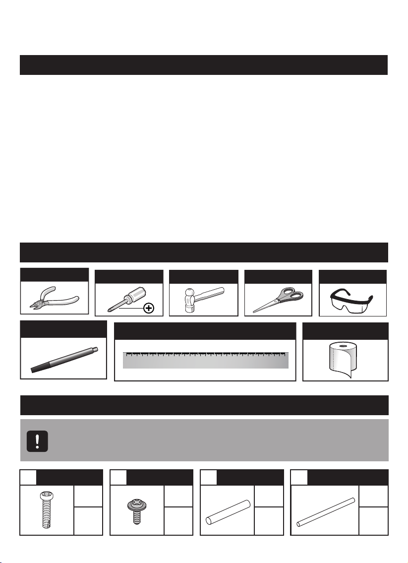
T o o l s Y o u M a y N e e d
D i a g o n a l C u t t e r
P e r m a n e n t M a r k e r
S c r e w d r i v e r
H a m m e r
R u l e r
C M
0 1 2 3 4 5 6 7 8 9 10 11 12 13 14 15 16 17 18 19 20 21 22 23 24 25 26 27 28 29 30
S c i s s o r s
S a f e t y G l a s s e s
T i s s u e P a p e r
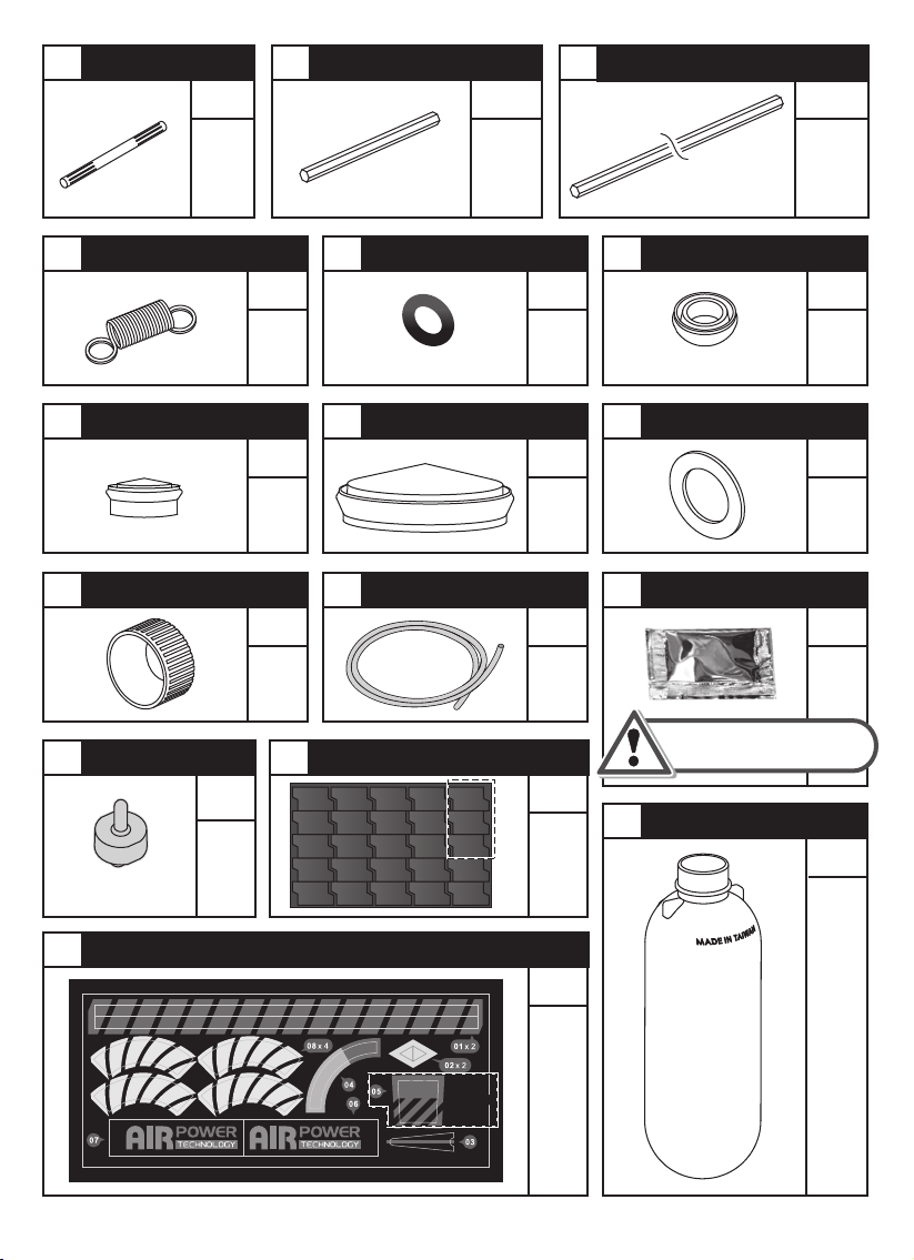
M e c h a n i c a l P a r t s L i s t
I m p o r t a n t : I f a n y p a r t s a r e m i s s i n g o r d a m a g e , D O N O T R E T U R N T O T H E
•
R E T A I L E R . E - m a i l u s a t s u p p o r t @ e l e n c o . c o m o r c a l l ( 8 0 0 ) 533- 2441
P r o d u c t c o n t a i n s f u n c t i o n a l e d g e s a n d s h a r p p o i n t s .
•
T a p p i n g S c r e w T a p p i n g S c r e w R o u n d S h a f t R o u n d S h a f t
P 1 P 2 P 3 P 4
Q T Y
Pu m p C ylinder
Q T Y Q T Y
6
120
1
Q T Y
1
Page 4
P5 P6 P7
QTY QTY
Hex Shaft (Short) Hex Shaft (Long)Round Shaft
QTY
1 1
P8 P9
P11 P12 P13
P14 P15
Spring O-ring (Black) Red Cap (Small)
QTY
QTY
1
P10
2
Red Cap (Medium) Red Cap (Big) Spacer
QTY
2
Silicon Tube
QTY
QTY
1
P16
QTY
11
Valve (Clear Blue)
P17 P18
QTY
Sponge
QTY
P20
Spare parts
(Spare part : 1 pc)
2
1
(Spare part : 1 pc)(Spare part : 1 pc)
Oil BagBottle Top
Do not touch the oil while
fitting the silicon tube.
PET Bottle
1
QTY
7
QTY
1
QTY
1
QTY
P19
Sticker
IgnoreIgnore
2
QTY
1
1
Page 5
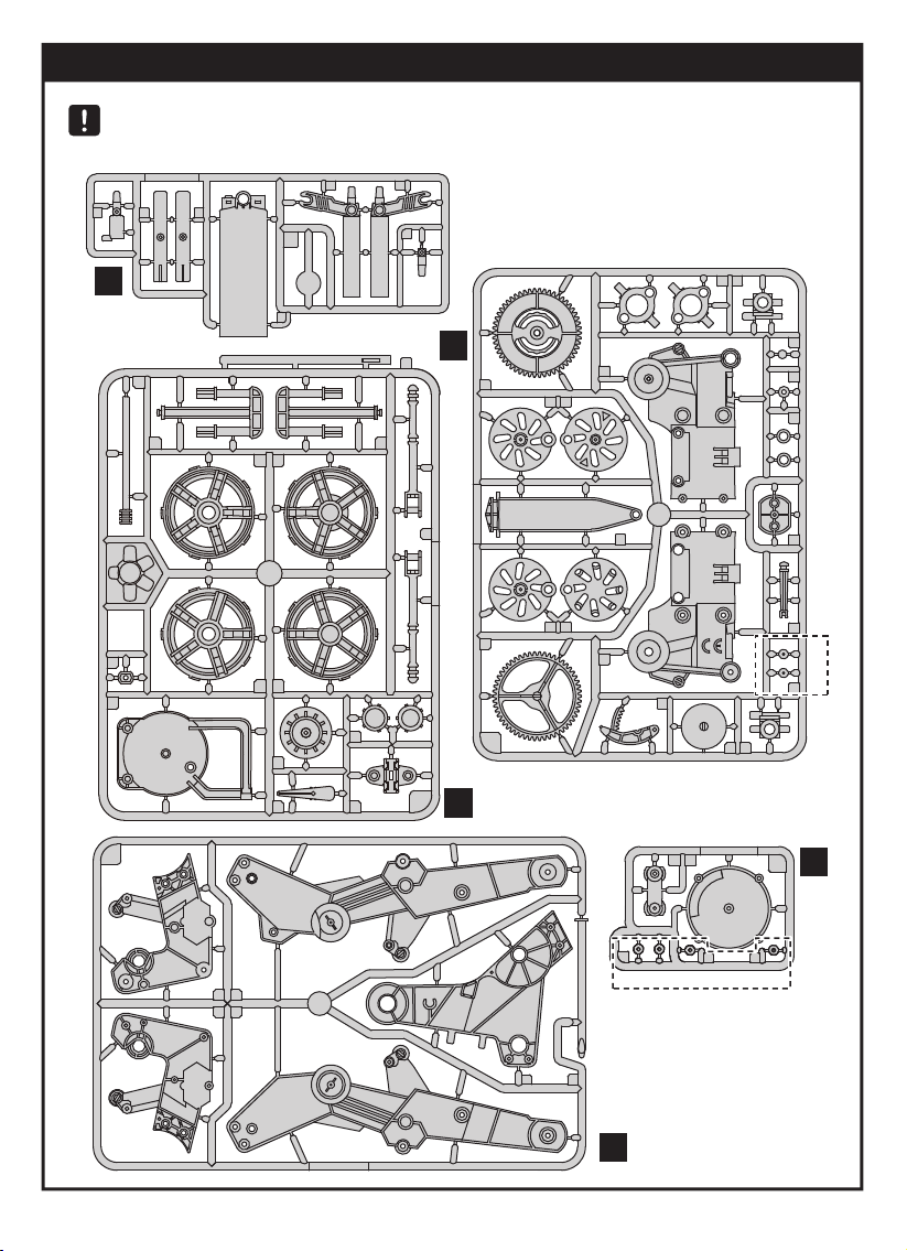
Plastic Parts
Cut the plastic parts when they are required.
Do not cut them in advance.
MADE IN TAIWAN
1
2
2
A
8
10
4
A
3
9
12
4
5
D
14
10
576
8
9
2019
10
18
13
MADE IN TAIWAN
OIL B7
6
9
1
11
MADE IN TAIWAN
2
1
D
3
2
4 5
B
B
C
1 2
3 4
6
MADE IN TAIWAN
4
3
11
12
MADE IN TAIWAN
2
1
3
3
17
16
Not Used
15
14
13
E
E
3
Not Used
5
C
3
Page 6
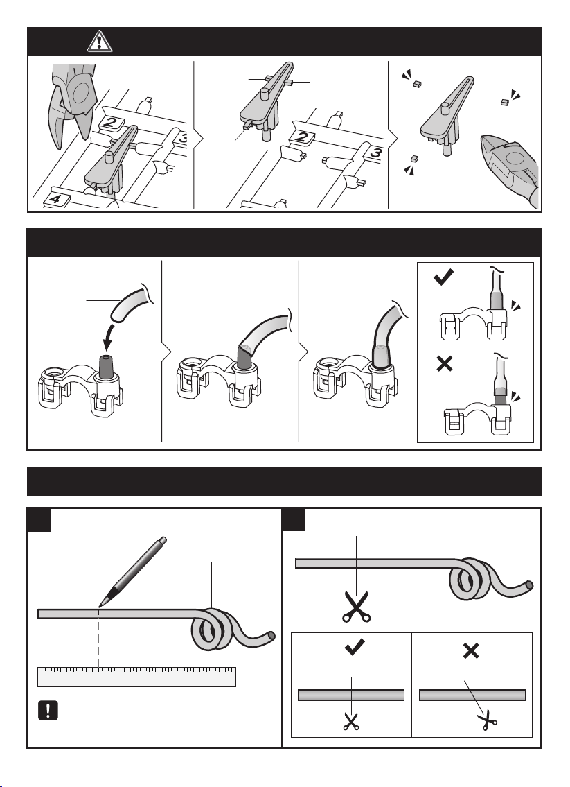
T i p : C u t O f f T h e B u r r s B e f o r e A s s e m b l y
Tu be
bu rr
bu rr
bu rr
H o w T o F i t A i r T u b e
Tilt the tu be
C orrect
I ncorrect
H o w T o C u t A i r T u b e
M eas u ring & M arking
1
F ollow the s tep s above: C u t the air
tu bes when they are req u ired.
D o not cu t them in advance.
P15
4
2
C u tting
C orrect
I ncorrect
Page 7
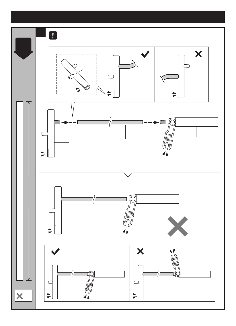
Tube Module A Assembly
Scale
1:1
1
Prepare air tube before assembly.
Correct
A2
A2
11cm
Incorrect
A4
2
4 5/16” | 11 cm
Correct
2
Incorrect
5
Page 8
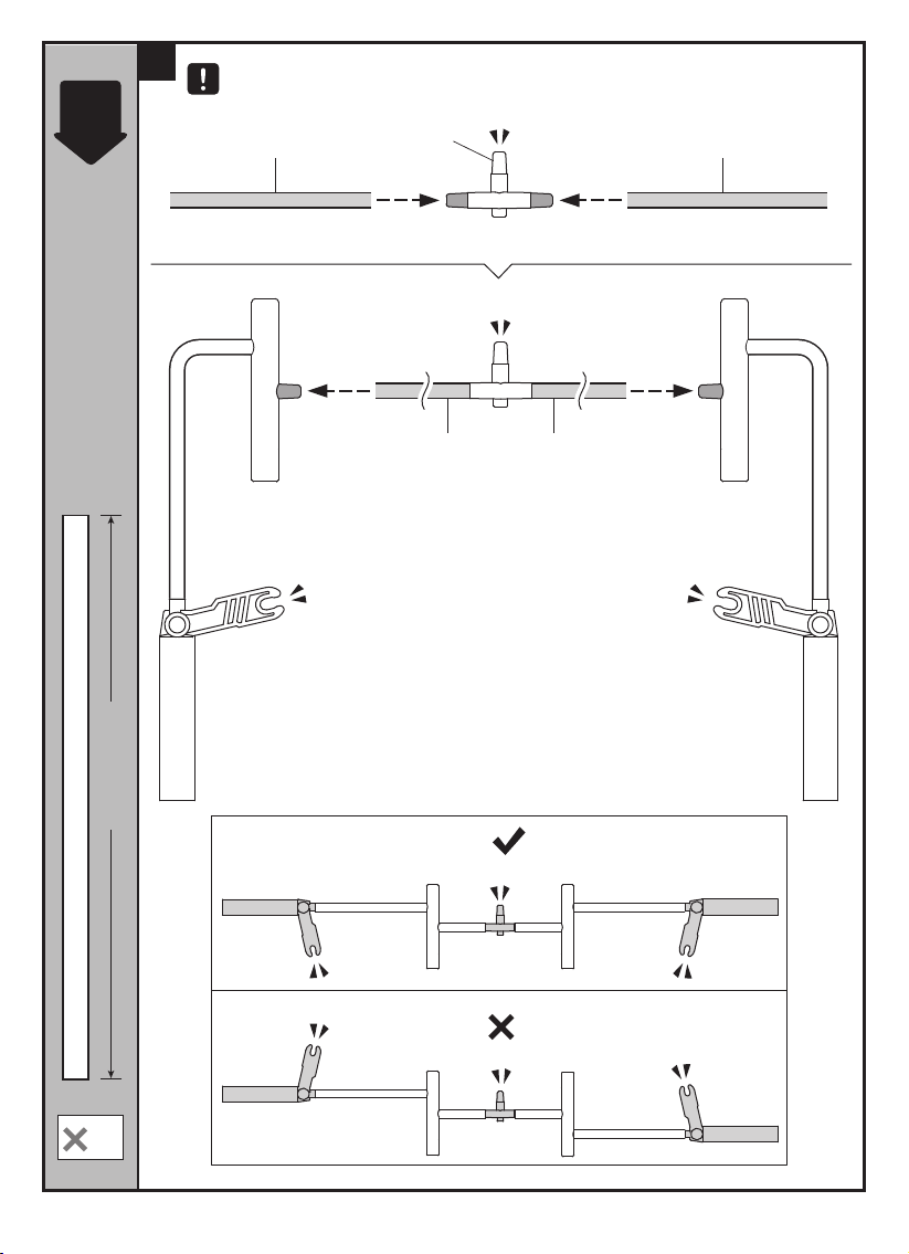
Scale
1:1
2
Prepare air tube before assembly.
9cm
A5
9cm 9cm
9cm
3 9/16” | 9 cm
2
Correct
Incorrect
6
Page 9
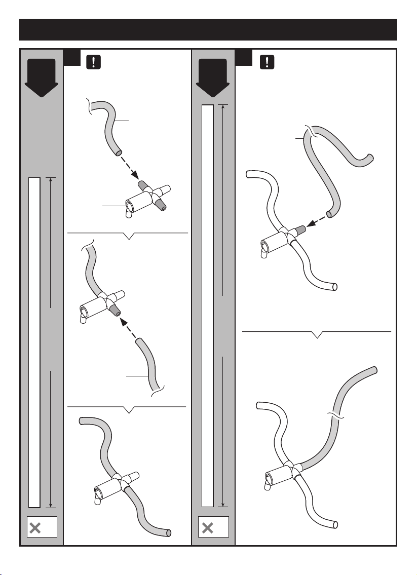
Tube Module B Assembly
Scale
1:1
1 2
4 1/2” | 11.5 cm
4 1/2” | 11.5cm
Prepare air tube
before assembly.
4 1/2” | 11.5cm
A1
Scale
1:1
Prepare air tube before
assembly.
5 1/2” | 14cm
5 1/2” | 14 cm
2 1
7
Page 10
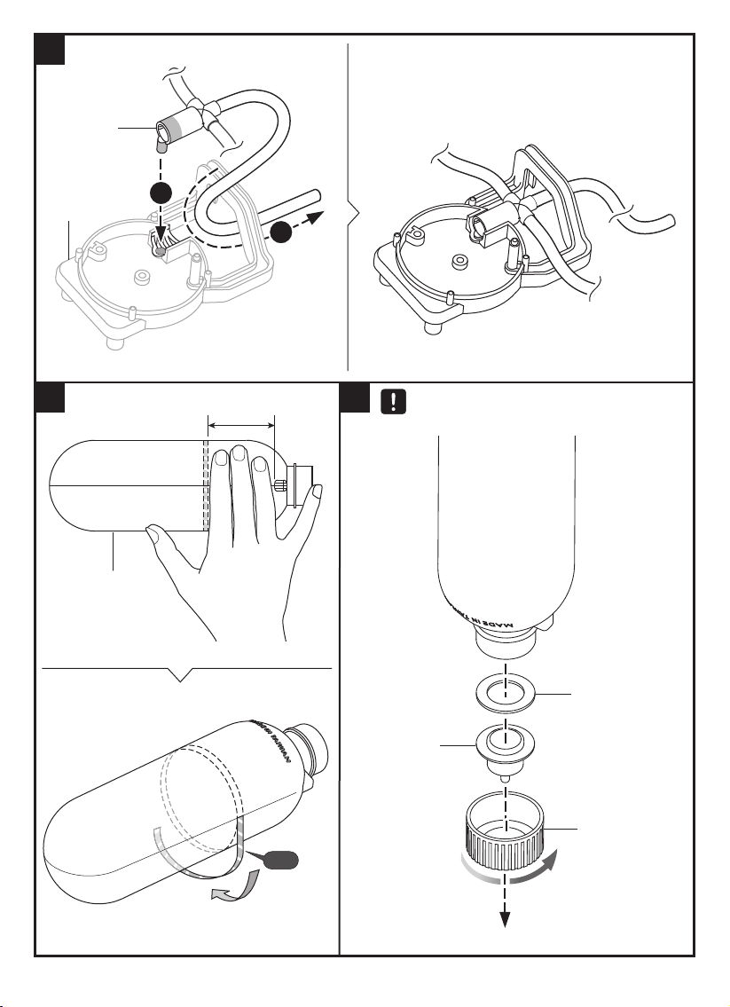
3
A1
B1
1
2
4
5
Screw on P14 onto PET bottle
tightly to avoid air leakage.
P20
P13
P19
01x2
B3
P14
8
Page 11
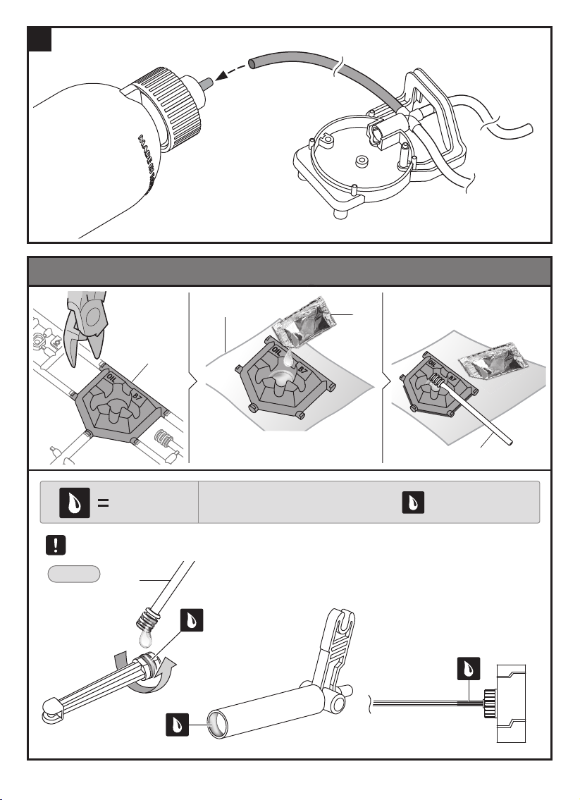
6
H o w T o O i l T h e P a r t s
B7
Ap p ly O il
Tis s u e Pap er
D o not s p ill any oil f rom the B7
oil bowl. K eep oil contained.
N ote : O il the p arts when ap p ears.
P16
D o not oil ou ts ide the noted s haded areas as s hown below.
Ex am p le:
B8
B8
9
Page 12
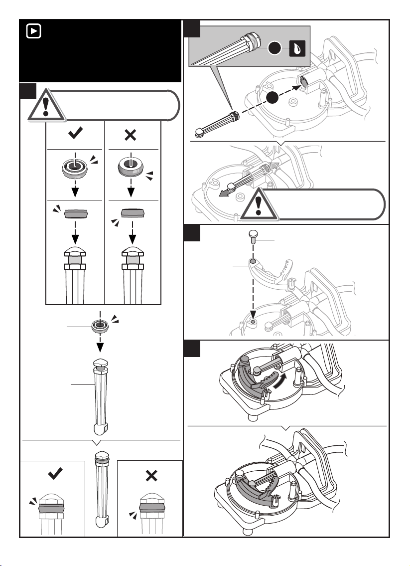
V i d e o T i p s
V i d e o T i p s
V iew a video on this p roj ect at
http s : / / www.elenco.com / teachtech/
To better u nderst and the asse m bly and op erations
of each p roj ect, view the V ideo Tip s .
8
1
7
Make sure P10 is placed in the
proper direction to avoid
air leakage.
C orrect
P10
Red Cap
(Small)
I ncorrect
2
Pu s h & p u ll the oiled p art
D 16 s everal tim es u ntil
it m oves s m oothly.
9
D 12
D 20
10
D16
C orrect
I ncorrect
10
Page 13
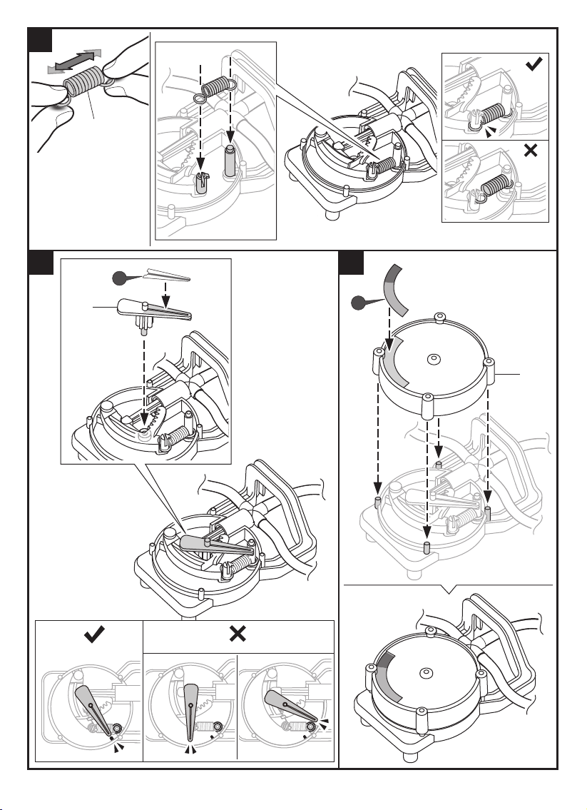
11
C orrect
P8
Note:
L ightly p u ll on both
ends of the s p ring to
m ake s u re it has good
s trength & ex tens ion
bef ore as s em bly.
12
03
P19
B2
I ncorrect
13
P19
04
E1
C orrect
I ncorrect
11
Page 14
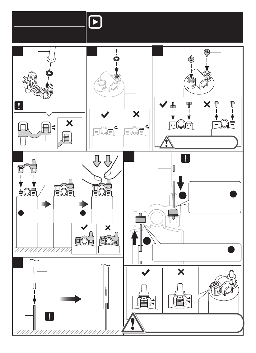
V a l v e A s s e m b l y
Pay clos e attention to the f ollowing
s tep s correctly to avoid air leakage.
V i d e o T i p s
V iew a video on this p roj ect at http s : / / www.elenco.com / teachtech/
1 2
C 5
E2
P9
O - ring
( Black)
U se C 5 to assi st you in
se tting P9 onto E2.
I ncorrect
E2
4
4
E2
A3
A3
1. Straight A3 on the table,
1 2
and p u t E2 on A3 f latly.
Snap E2 to A3 entirely to avoid
air leakage.
2. Press down
E2 to A3 entirely.
C orrect
5
B14
C orrect
I ncorrect
P9
O - ring
( Black)
A3
I ncorrect
6
C orrect
3
P17
C orrect
Ensu re the direction of two
P17 to avoid air leakage.
B14
2
Pu sh P17 to the top ( as p er F ig )
and m ake P9 to se t f latly.
I ncorrect
I ncorrect
U se B14 to inse rt
( O - ring) two P9.
Pu s h P17 to the
bottom ( as p er F ig )
1
and m ake P9 f lat
agains t bas e.
P17
1
1
2
P4
Place P4 on the
table, cap B14 to P4
as sh own .
I f P9 ( O - R ing) was se t im p rop erly as sh own
in above incorrect ( X ) f ig, re- do st ep 6 again.
12
Page 15
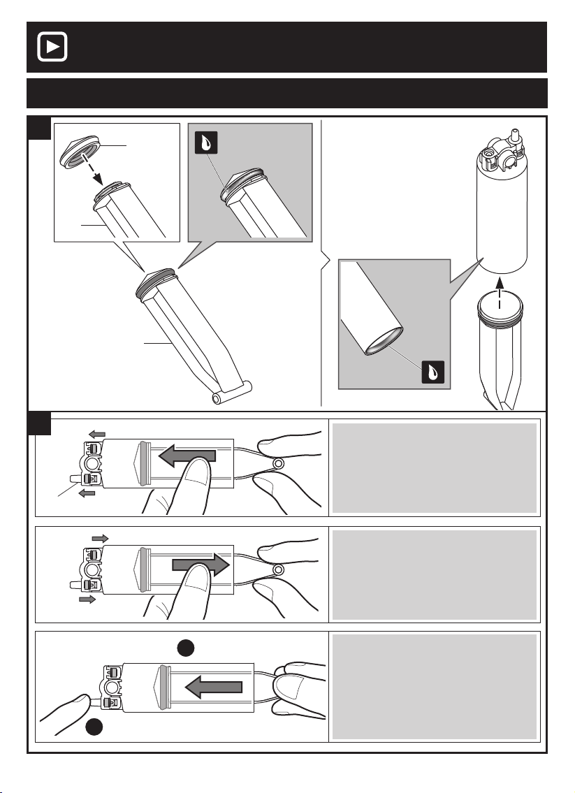
1
2
P17
V i d e o T i p s
R ed C ap ( Big)
D 4
V iew a video on this p roj ect at http s : / / www.elenco.com / teachtech/
T e s t i n g A i r L e a k s – T h e V a l v e
P12
D 4
M ake su re that both P17 m ove in the
direction indicated by the arrows when
D 4 is p u sh ed in.
Pu sh in the D 4.
2
1
Seal the hole of the boss si de with a f inger.
M ake su re that both P17 m ove in the
direction indicated by the arrows when
D 4 is p u lled back.
C onf irm that D 4 cannot be p u s hed
in eas ily.
13
Page 16
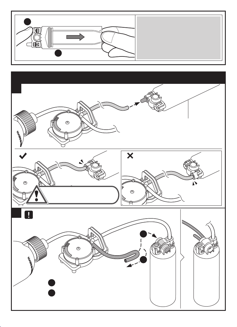
Seal the inlet hole with a f inger.
1
M ake su re D 4 is f irm , when p u lling
D 4 back.
Pu ll the D 4 back.
2
A i r l e a k a g e t e s t i n g – T u b e M o d u l e B
1
E2
C orrect
2
I ncorrect
I ns tall E2 in the correct
p os ition as s hown above.
F old the tu be and inse rt it into the hole as sh own below.
2
1
F old the tu be.
1
2
I nse rt the f olded tu be into the hole.
14
Page 17
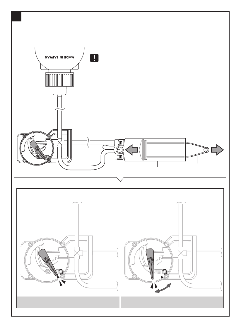
3
H old A3 f irm ly!
R ep eat a “ Pu s h & Pu ll” m ovem ent u s ing D 4
15 - 20 tim es to collect air into PET bottle.
C heck that the p res s u re m eter p ointer s wings
to the lef t and holds its p os ition.
R es u lts s hown below will reveal if tu be
m odu le B is ins talled correctly or is leaking air .
A3
A i r L e a k a g e W o r k i n g F u n c t i o n a l l y
Pointer st ays st ill Pointer m oves to the above p osi tion
15
D 4
Page 18
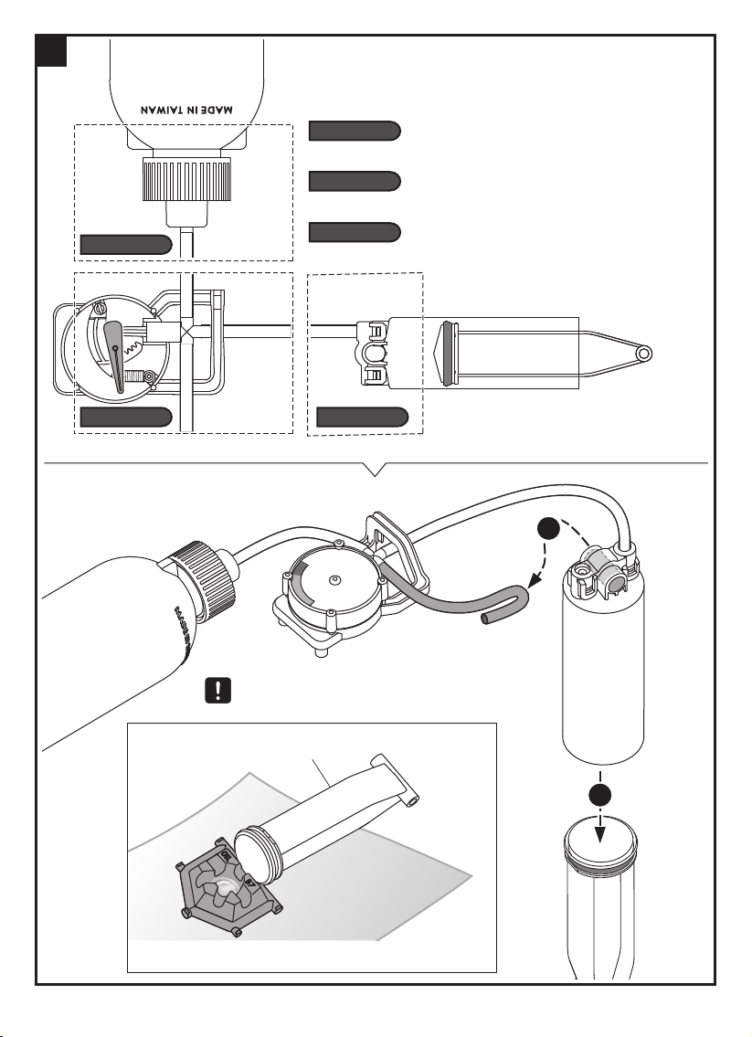
4
C h e c k t h e f o l l o w i n g l o c a t i o n s i f a i r l e a k s o c c u r r e d ,
a n d r e - i n s t a l l a s b e l o w :
L ocation 1:
Back to p age 8 , and re- ins tall s tep 5 again.
L ocation 2:
Back to p age10, and re- ins tall s tep s 7 - 13 again.
L ocation 1:
L ocation 2: L ocation 3:
L ocation 3:
Back to p age12, and re- ins tall s tep s 1- 6 again.
1
Be su re to rem ove air tu be & D 4
f rom A3 af ter test ing.
D 4
Place D 4 on B7 to avoid oil sp ills.
16
2
Page 19
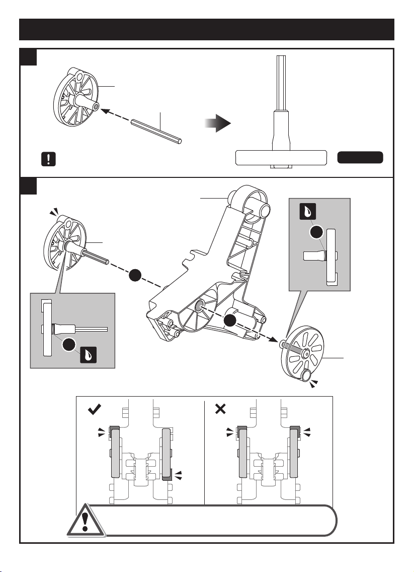
Vehicle Body Module Assembly
1
D5
P6
Insert the hex shaft P6 into the D5 as
shown in the right fig. ( scale 1:1 )
Scale 1:1
2
C6
1
D5
2
2
1
D2
Correct
Incorrect
Make sure parts D2/D5 are at opposite positions.
17
Page 20
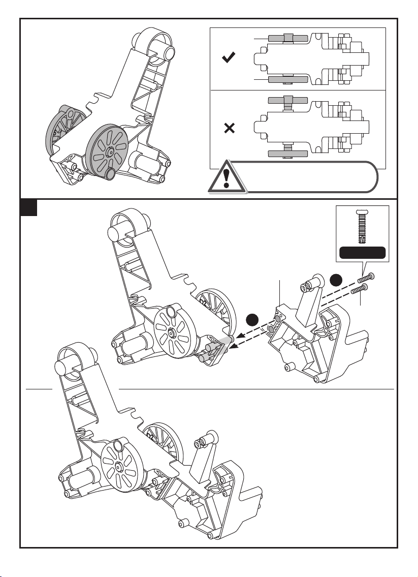
D5
Correct
D2
Incorrect
Make sure parts D5 & D2 are
properly connected as
shown above.
3
Scale 1:1
C3
2
P1x2
1
18
Page 21
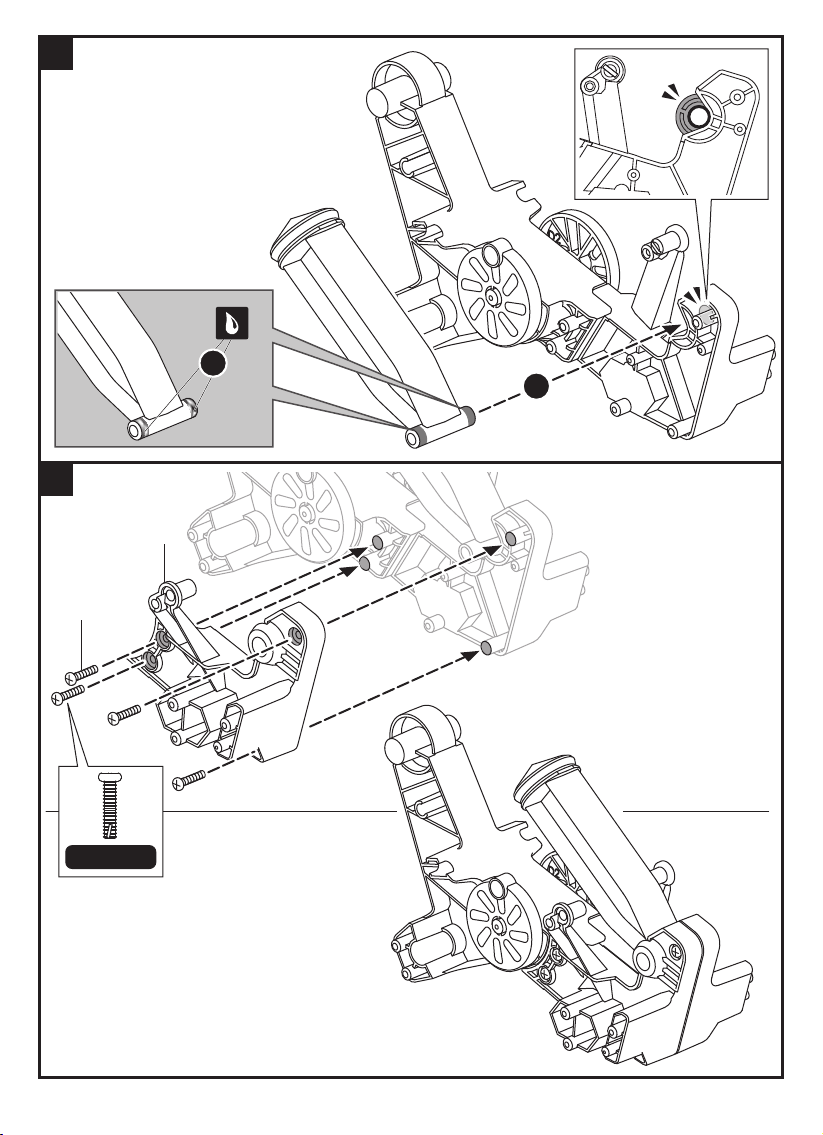
4
5
1
2
C1
P1x4
Scale 1:1
19
Page 22
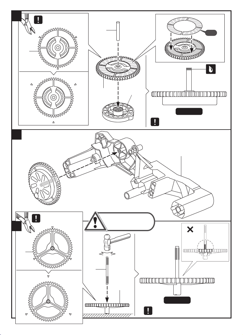
6
D 7
C u t of f bu rrs
bef ore as s em bly.
P3
P19
08x4
D 7
D 3
S c a l e 1: 1
I nse rt P3 to the bottom to m atch
f ig sh own above. ( sca le 1: 1 )
7
C 2
C u t of f the bu rrs
bef ore as s em bly.
8
D 1
Slightly ham m er
P5 into D 1.
I ncorrect
P5
D 1
S c a l e 1: 1
I nse rt P5 to the bottom to m atch
f ig sh own above. ( sca le 1: 1 )
20
Page 23
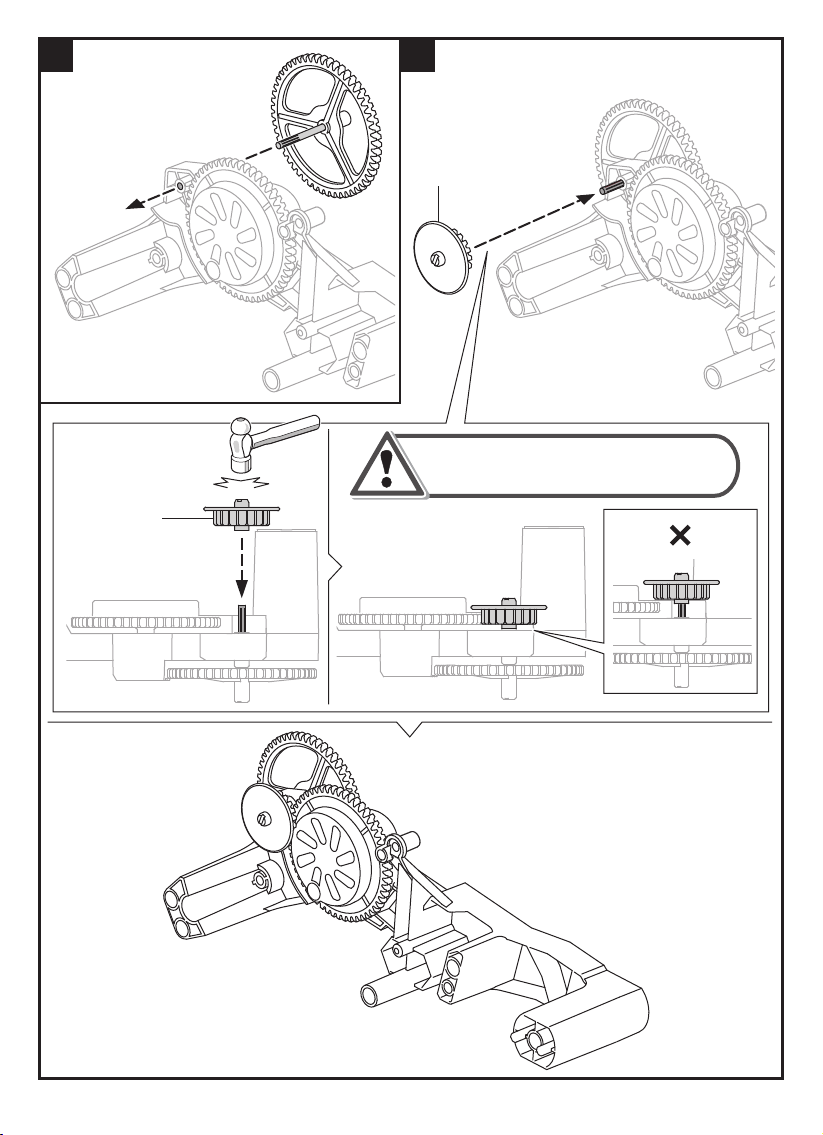
9
D13
10
D13
Gently tap D13 with hammer to
the bottom as shown below.
Incorrect
21
Page 24
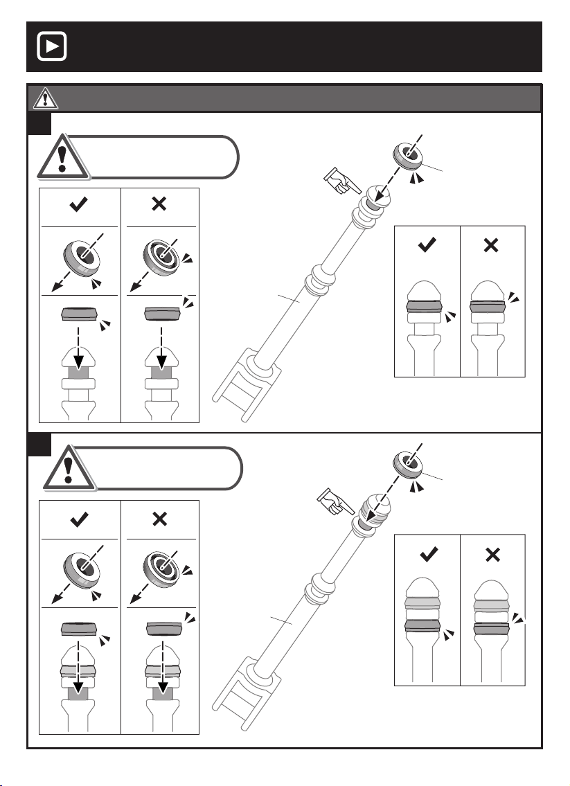
Video Tips
View a video on this project at https://www.elenco.com/teachtech/
Make Sure P10 Set To B13 Step By Step As Shown Below.
11
Ensure that P10 is inserted
Ensure that P10 is inserted
in the proper direction to avoid
in the proper direction to avoid
air leaks.
air leaks.
P10 Red Cap
(Small)
12
Correct
Ensure that P10 is inserted
in the proper direction to avoid
air leaks.
Correct
Incorrect
Incorrect
B13
B13
Correct
Incorrect
Tip : Use C5 to assist you
in setting P10 easily.
P10 Red Cap
(Small)
Correct
Incorrect
Tip : Use C5 to assist you
in setting P10 easily.
22
Page 25
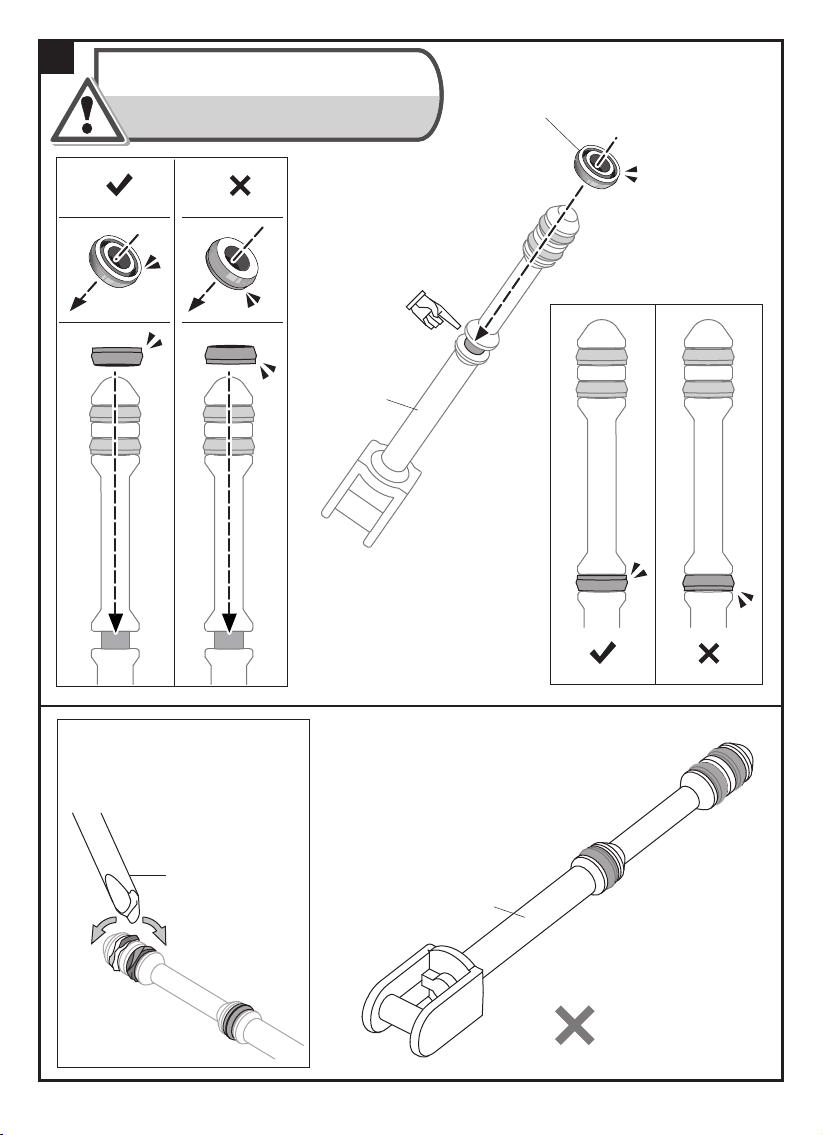
13
Ensure the direction of P10 to avoid
air leakage.
Note: Direction of P10 on step 13 is
different from step 11 & 12.
P10 Red Cap
(Small)
Correct
Tip :
Use C5 to make it
smooth if P10 was
twisted during assembly.
Incorrect
B13
Tip : Use C5 to assist you
in setting P10 easily.
.
Correct
Incorrect
C5
B13
2
23
Page 26
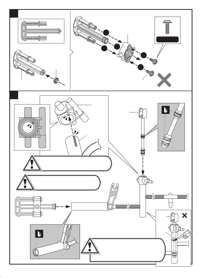
14
15
B10
D 9
P11
R ed C ap
( M ediu m )
D 9
A2
N o t e :
M ake s u re to lock A2 / D 9 f irm ly.
1
1
D 8
S c a l e 1: 1
1
2
2
P2x2
B13
2
D o n o t m i x u p D 9 & D 14, m a k e
s u r e t o u s e D 9 f o r a s s e m b l y .
Take ou t B13 if P10 ( R ed C ap )
was twist ed du ring asse m bly.
U n- twist P10 and re- inse rt
B13 into A2.
24
B13
P10
I ncorrect
Page 27
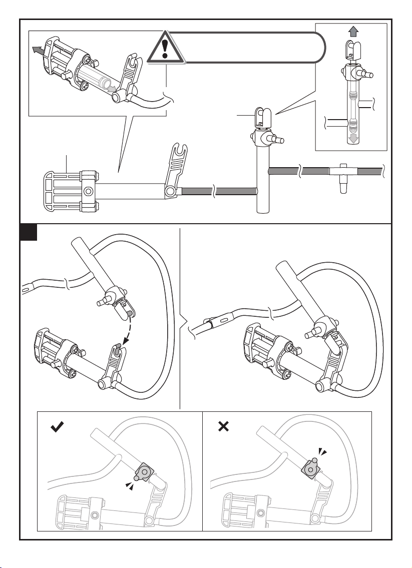
Pu sh & p u ll the oiled p art B10/ B13
se veral tim es to m ake them
work sm oothly.
B13
B10
16
C orrect
I ncorrect
25
Page 28
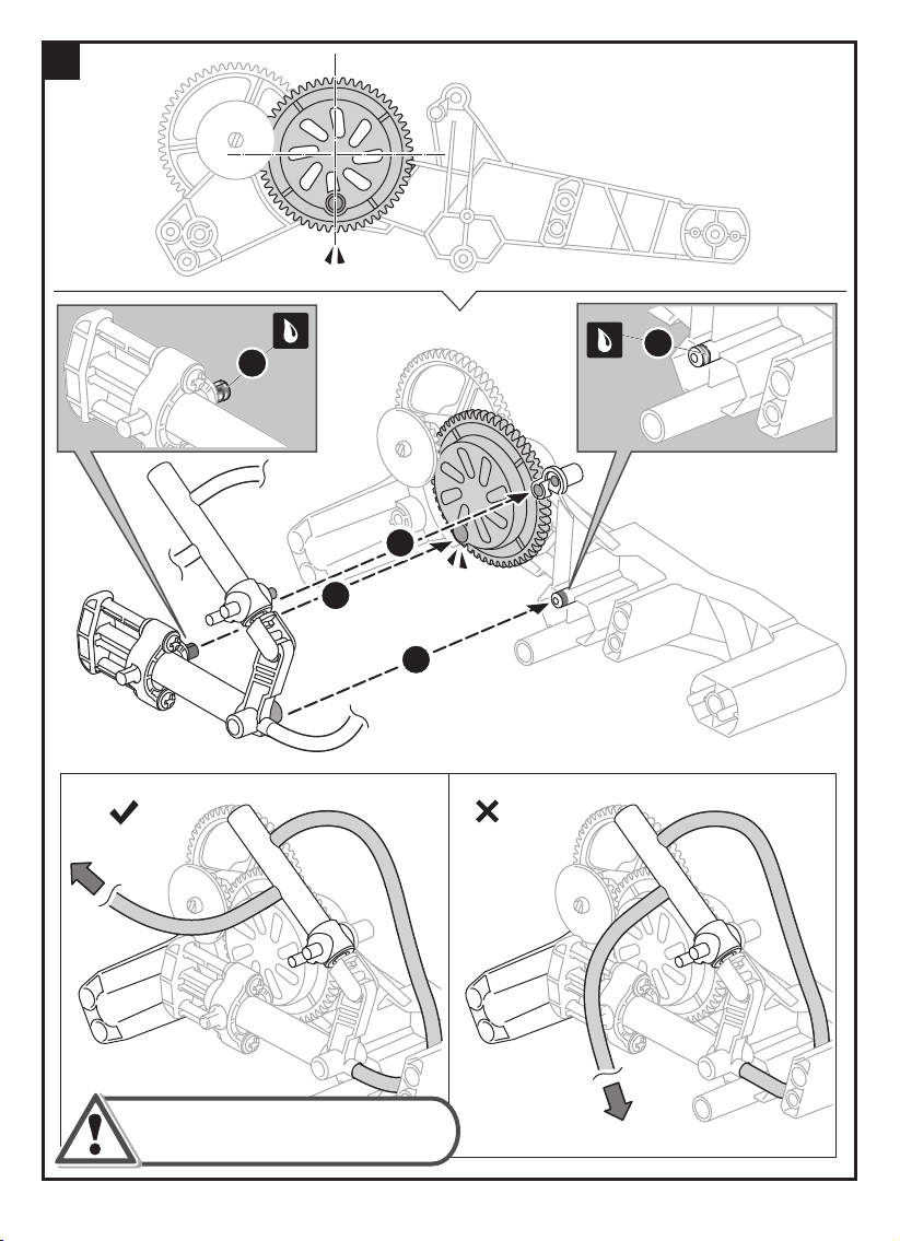
17
Correct
1
1
2
4
3
Incorrect
Route the air tube to the position
as shown above.
26
Page 29
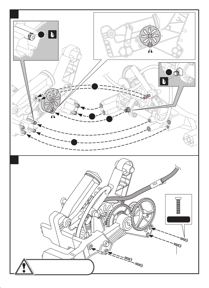
18
1
1
5
19
4
Make sure the airtube is
facing the correct direction .
2
3
Scale 1:1
P1x4
27
Page 30
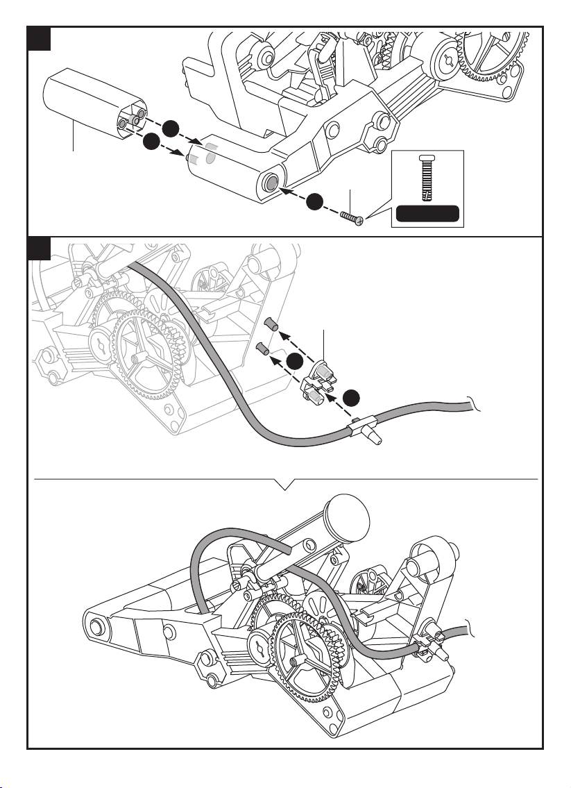
20
21
1
1
D17
P1
2
Scale 1:1
B4
1
2
28
Page 31
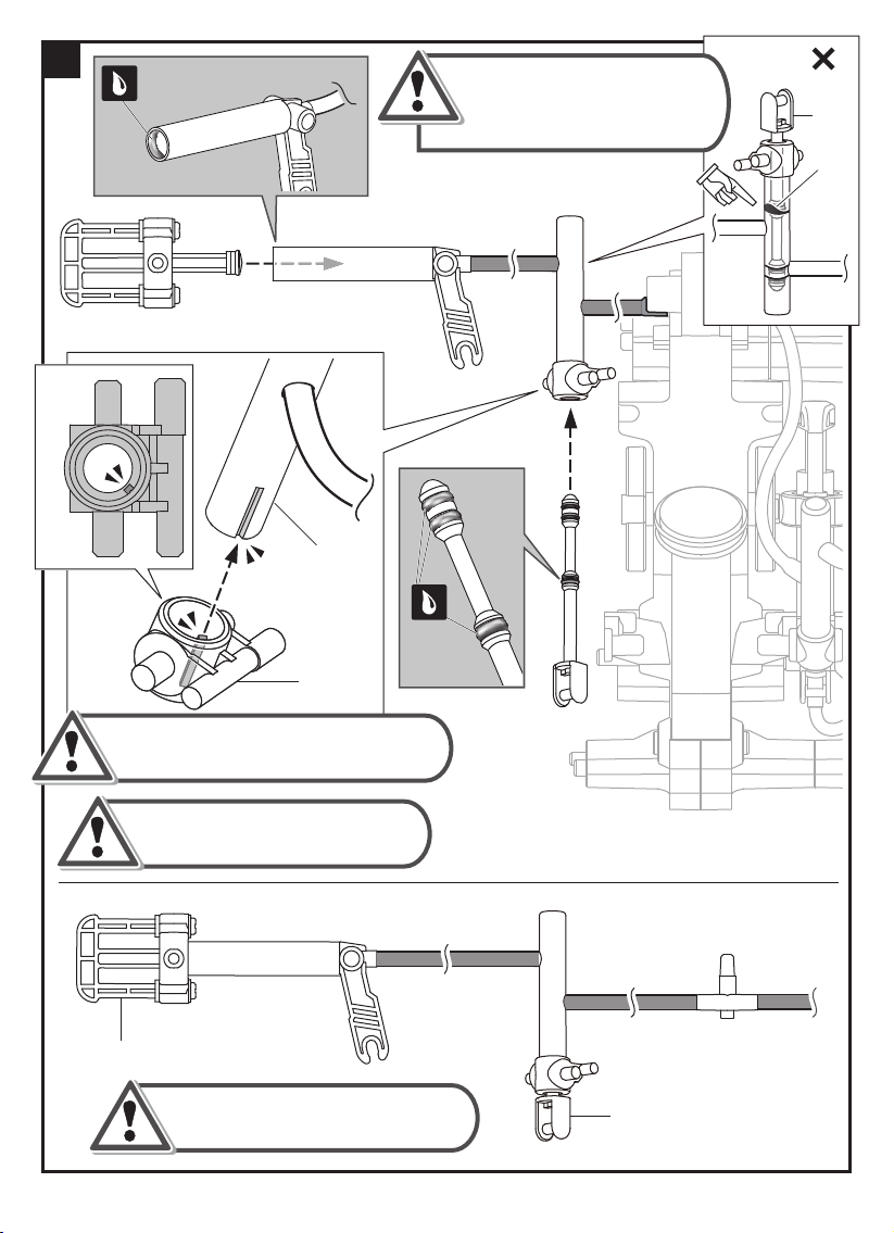
22
D 14
A2
D 14
Take of f B13 if P10 ( R ed C ap )
was twis ted du ring as s em bly.
U ntwis t P10 and re- ins ert
B13 into A2.
I ncorrect
B13
P10
N o t e :
M ake su re to lock A2 into D 14 f irm ly.
D o n o t m i x u p D 9 & D 14, m a k e
s u r e t o u s e D 14 f o r a s s e m b l y .
B10
Pu sh & p u ll oiled p arts B10 and B13
se veral tim es to m ake su re they
m ove sm oothly.
B13
29
Page 32
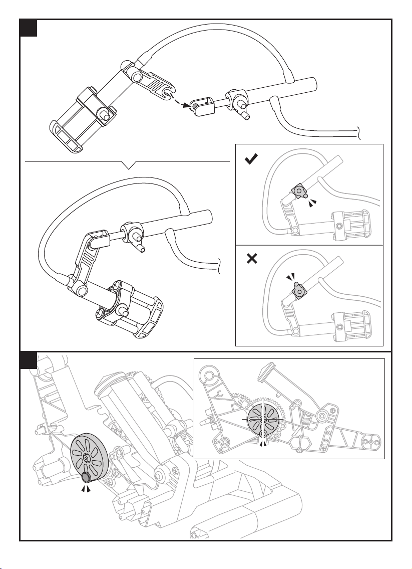
23
Correct
Incorrect
24
30
Page 33
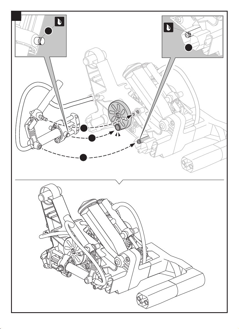
25
1
1
2
4
3
31
Page 34
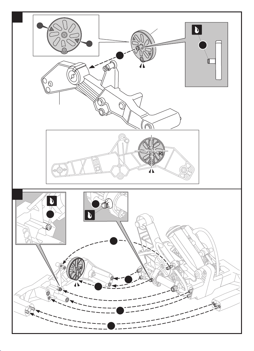
26
27
P19
02
D6
P19
02
1
2
C4
1
1
6
2
3
4
5
32
Page 35
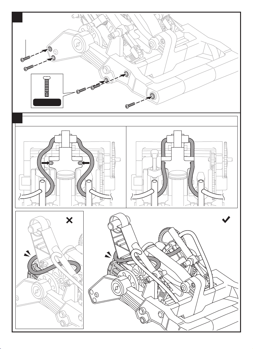
28
P1x5
Scale 1:1
29
Top View
Correct Incorrect
33
Page 36
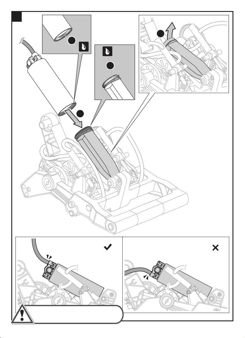
30
1
2
3
4
Ensu re the correct direction
of air tu be.
C orrect I ncorrect
34
Page 37
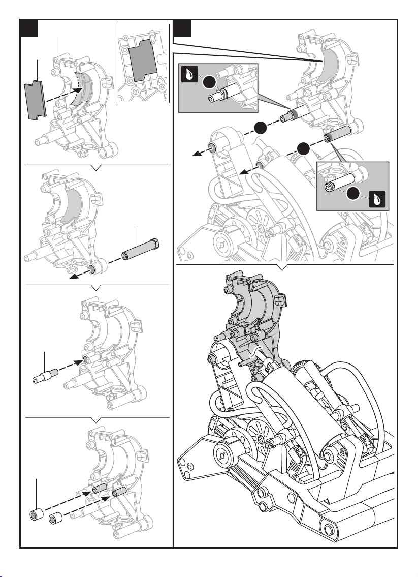
31 32
D10
P18
B6
1
2
2
1
D19
D18x2
35
Page 38
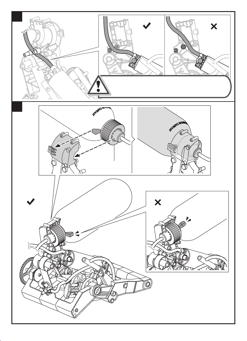
33
34
Correct Incorrect
Make sure air tube is installed at a right position
as shown above. If positioned wrong, air tube
may fail to pump.
PET Bottle
Correct
Incorrect
36
Page 39
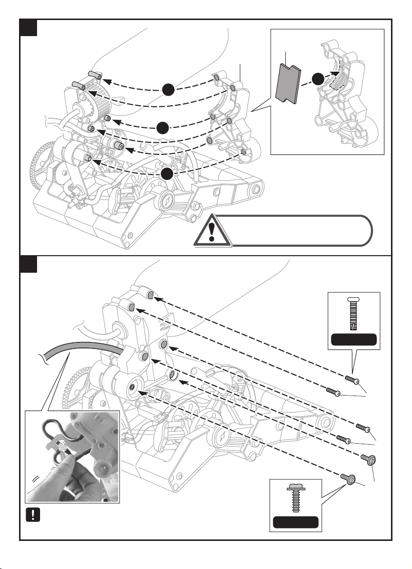
35
36
P18
D11
1
2
2
2
Be careful not to clamp the
air tubes during assembly.
Check if air tubes are clamped during assembly .
Pull the tube (as shown above) to make sure it is
moving freely .
37
Scale 1:1
P1
P1
P2
Scale 1:1
Page 40
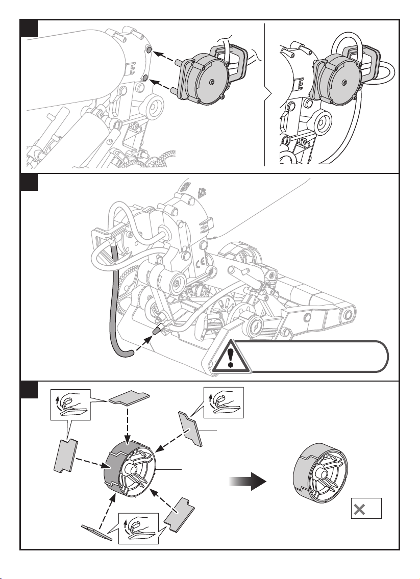
37
38
39
Make sure there is no oil on
connector for assembly.
P18x5
B9
2
38
Page 41
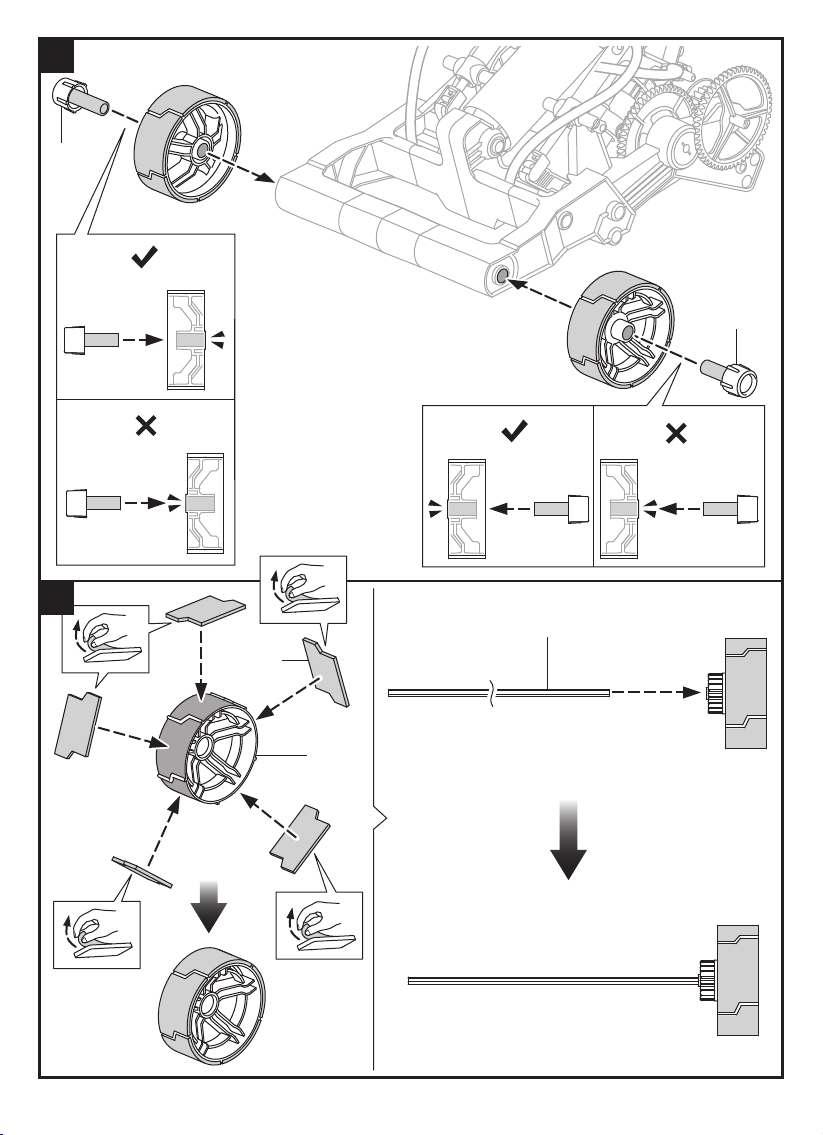
40
B5
Correct
B5
41
Incorrect
Correct Incorrect
P7
P18x5
B12
39
Page 42
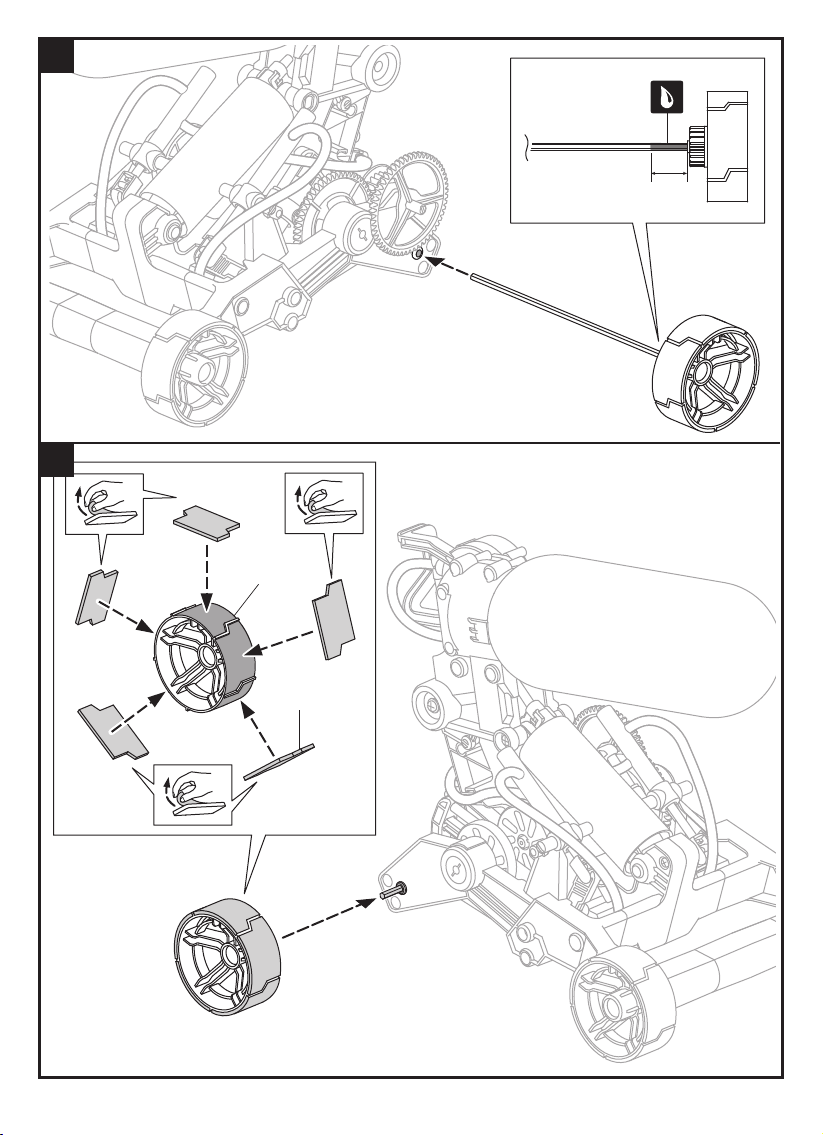
42
43
1cm
B11
P18x5
40
Page 43
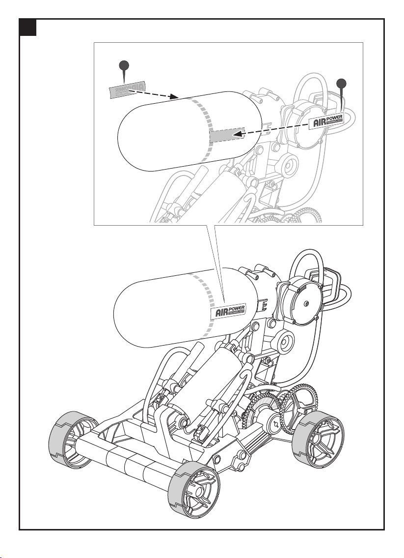
44
F i n i sh ed
P 19
06
P 19
07
4 1
Page 44
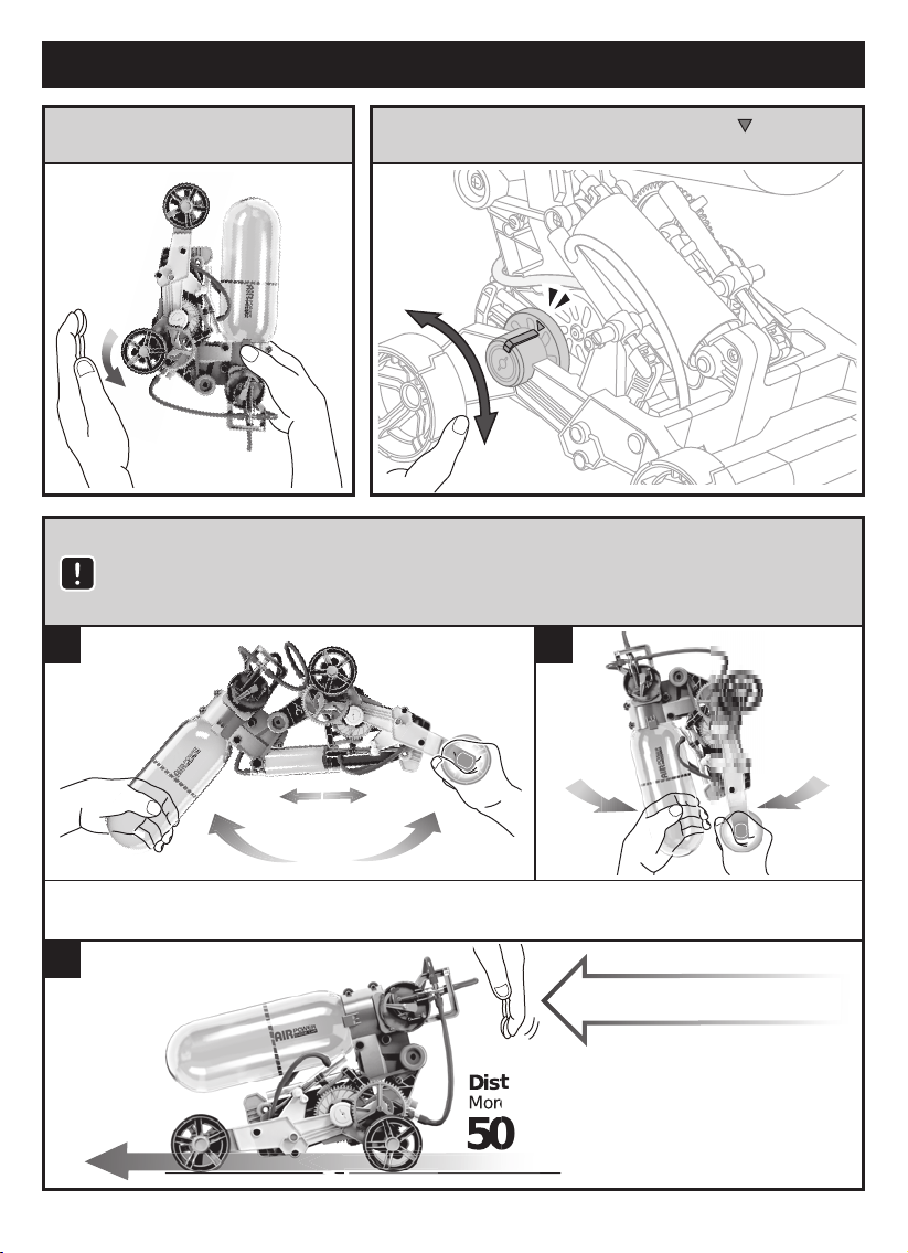
H o w T o P l a y
1. Sp in the rear wheel ( as below)
to release air com p letely.
3.Pu m p ing as below f igu res .
I n t h e b e g i n n i n g , p u m p u p a t l e a s t 20 t i m e s t o s t a r t .
( To obtain the bes t res u lts , do not s top p u m p ing u ntil p res s u re m eter
m easu red and p ointed to the red range.)
1
2. Rotate the rear wheel and have the ˝ ˝ align to
the p rotru si on bar ( as below) , then st art to p u m p .
2
As an eq u ip p ed sa f ety device, ex cess air will be au tom atically release d once
p ressu re m eter is in the “ red” range.
3
P U S H T O G OP U S H T O G O
D i s t a n c e
M ore Than
50 M
42
Page 45
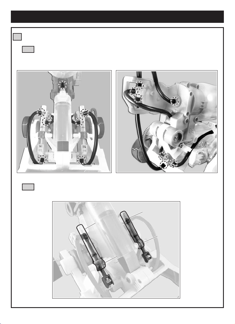
Trouble Shooting
Check if pressure meter can not gauge to red range, or if air leaks from anywhere.
1
Check if air tubes are installed correctly. ( Below marked positions to help you
1-1
quick check the air tubes, for exact assembly steps - refer to page 4
“ How T o Fit Air Tube ” )
Check if D9,A2 / D14, A2 are loose..
1-2
( refer to page 24, step 15 & page 29, step 22 )
A2
A2
D9
D14
43
Page 46
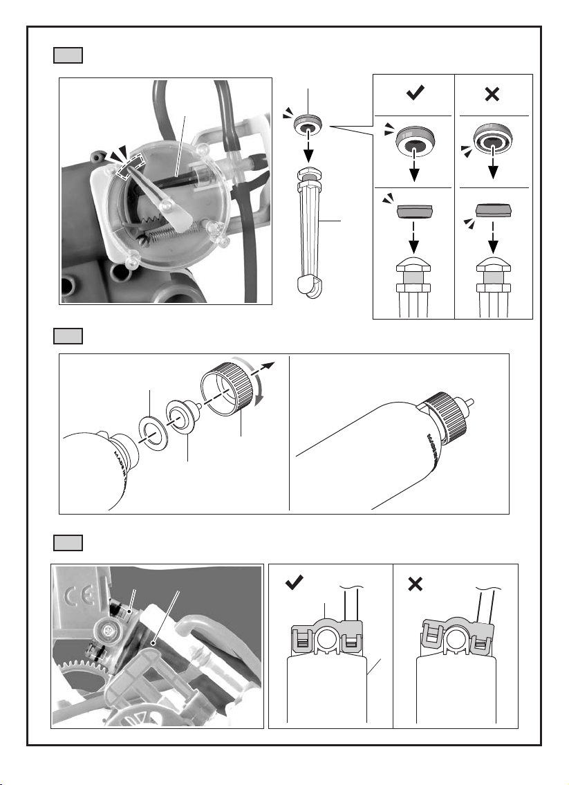
Check if P10 & D16 are installed correctly. ( refer to page 10, step 7 )
1-3
Red Cap
P10
(Small)
D16
D16
Check if P14 is fastened tightly. ( refer to page 8, step 5 )
1-4
P13
P14
Correct Incorrect
B3
Check if E2 / A3 are loose. ( refer to page 12, step 4 )
1-5
E2
A3
Correct
44
E2
Incorrect
A3
Page 47
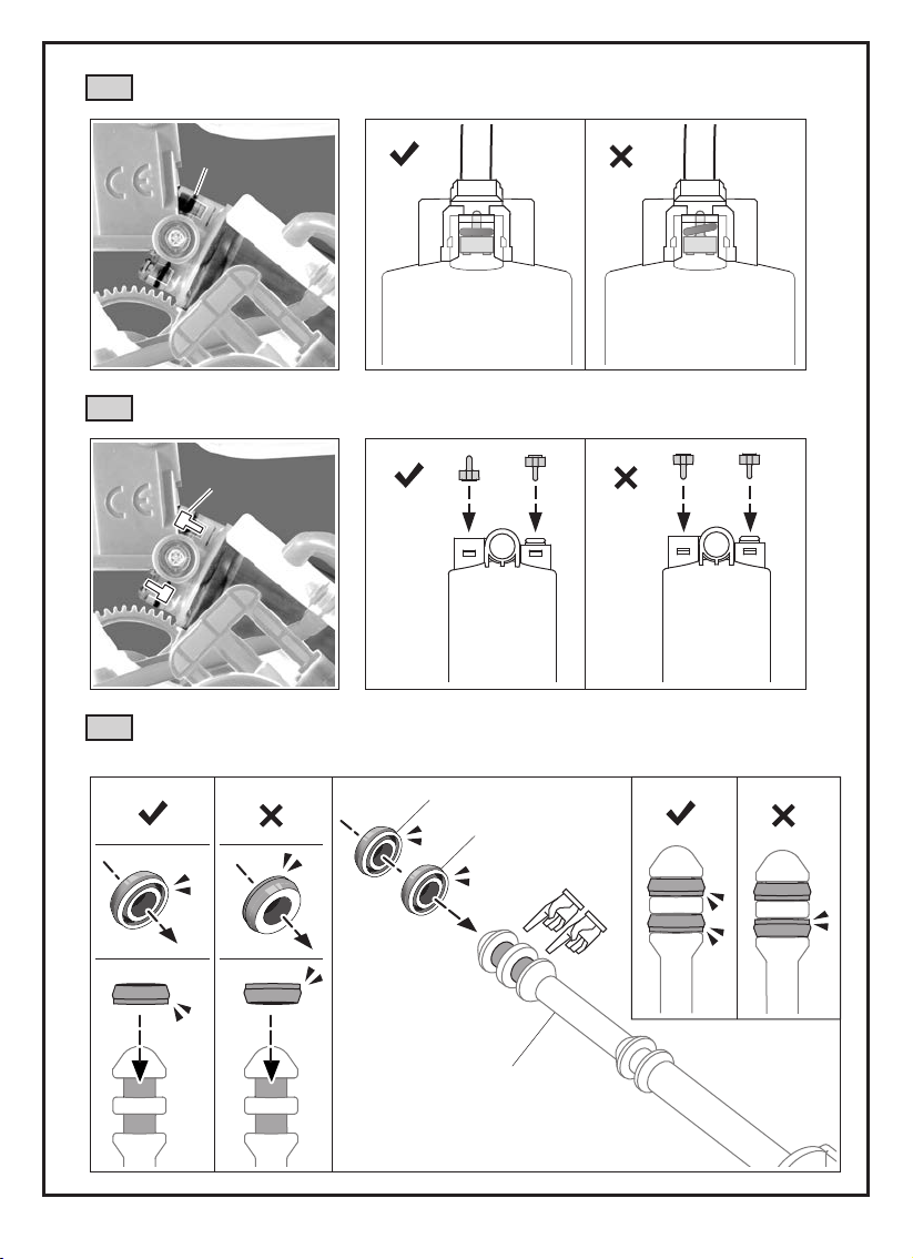
C heck if P9 ( O - ring) is se ated f lat. ( ref er to p age 12, st ep 6 )
1- 6
P9
C orrect I ncorrect
1- 7
C heck if P17 is inst alled in the right direction. ( ref er to p age 12, st ep 3 )
P17 x 2
C orrect
1- 8
C heck if P10/ B13 are inst alled in the correct direction.
( ref er to p age 22, st ep s 11~ 13)
P10 R ed C ap
( Sm all)
I ncorrect
C orrect I ncorrectC orrect I ncorrect
B13
45
Page 48
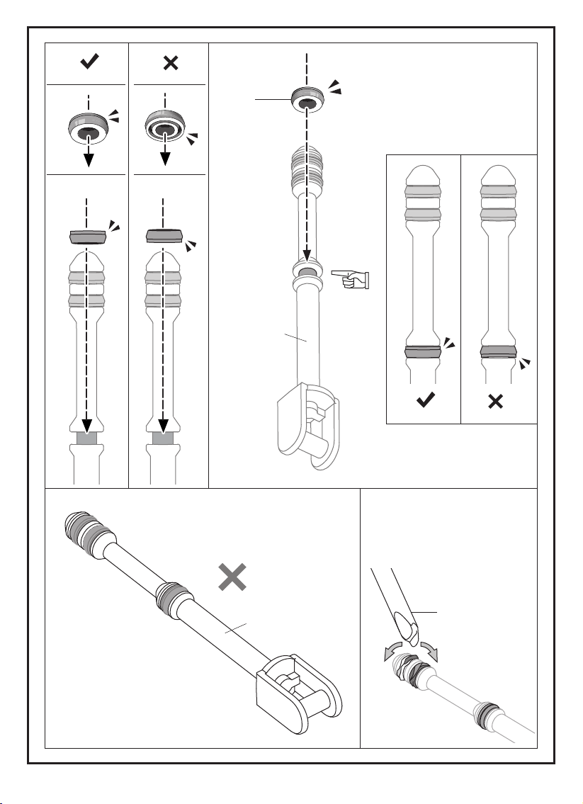
C orrect I ncorrect
P10
R ed C ap
( Sm all)
B13
C orrect I ncorrect
2
B13
T i p :
U se C 5 to adj u st if P10
was twist ed du ring
asse m bly.
C 5
46
Page 49
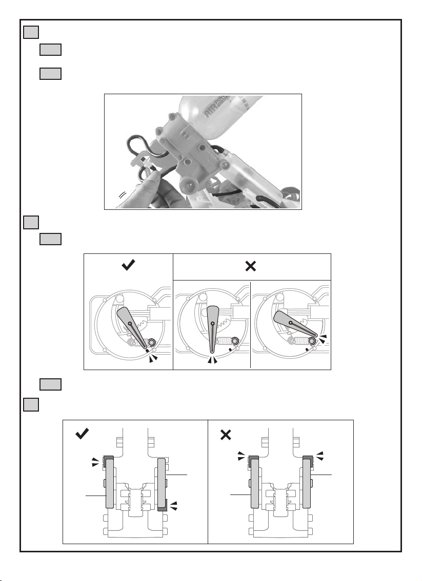
If air tubes are loosened while pumping.
2
Check if connectors have oil on surface. Take off the connectors/air tubes, make
2-1
sure to wipe off the oil and use neutral detergent to clean the parts thoroughly.
Check if air tubes are kinked or clamped during assembly. Slightly pull the tube
2-2
(as shown below) to make sure it is moving freely .
3
If the pressure meter does not function while pumping.
Check if pointer is installed correctly ( refer to page 11, step 12 )
3-1
Correct Incorrect
Check if air tubes are clamped ( refer to Trouble Shooting 2-2 )
3-2
4
Check if D2 / D5 are installed in the right direction. ( refer to page17, step 2 )
Correct
D5
D2
Incorrect
D2
D5
47
Page 50

Notes
48
Page 51

Notes
49
Page 52

150 Carpenter Ave.
Wheeling, IL 60090, USA
(847) 541-3800 or (800) 533-2441
elenco.com
CHOKING HAZARD. Small Parts.
Not for children under 3 years old.
No part of this book shall be reproduced by any means: electronic, photocopying,
or otherwise without written permission from the publisher.
Printed in Taiwan
US Patent D762269 S
Not responsible for typographical errors.
TM
Teach Tech
Copyright© 2019 Elenco Electronics Inc. All rights reserved.
is a trademark of Elenco Electronics Inc.
753182
4350008951
 Loading...