

Page 1

owner’s manual
Infrared Wireless Microphone System
Page 2

Maxim III
owner’s manual
Page 3

notes
Date of Purchase:
Model Number:
Serial Number:
Notes:
Page 4

Maxim III
owner’s manual
thank you
Congratulations on the purchase of your new Maxim
III Infrared Wireless Microphone Sound System. You
can be assured that the Maxim III fulfills all
specifications and was produced to very high
quality control standards. TeachLogic incorporates
the latest state of the art technology, employs the
most advanced manufacturing methodology and
uses only premium quality components to assure
many years of reliable performance. We appreciate
your confidence by your selection of our product. It
is TeachLogic’s intent to uphold that confidence by
providing factory assistance and dealer support.
We hope you will take the time to view this manual
to familiarize yourself with the product operation
and features. This manual will help you learn to use
and gain the maximum benefit of the Maxim III
system. The manual provides a basic explanation on
the principles and advantages of infrared
transmission. Followed by the system description,
operation and installation instructions, the manual
will conclude with maintenance and troubleshooting
procedures.
contact
If you should encounter
some unresolved issue,
please contact TeachLogic
customer service department for further assistance.
Brian Van Waay
President
1
•800•588• 0018
sales @teachlogic.com
1
•760•631•1283
www.teachlogic.com
4
Page 5

safety instructions
Read Instructions
All safety and operation instructions should be read
before operating this TeachLogic product.
Retain Instructions
Safety and operating instructions should be kept
for future reference.
certifications
US CA
Listed
TeachLogic systems are
manufactured using leadfree processes and are free
of materials harmful to the
environment. They conform
to the most stringent new
European guidelines for
consumer products (RoHS).
caution
Recycle—Do not dispose
rechargeable batteries in
trash. Actually it is unlawful
to do so in CA, NY & ME.
Contact: Earth911.com
1-800-CLEANUP
Save our resources and
don’t contaminate.
Go Green
Water & Moisture
This product should not be operated near water.
Heat Environment
Do not subject this product to excessive heat
conditions.
Power Source
This product must be connected to an AC power
source per the voltage input specified and marked
on the power supply.
Power Cord Caution
Power cable should be routed clear of foot traffic
and supported clear of kinking or abrasion.
Object Protection
Locate the operating unit so it will not be subjected
to falling objects or water entry.
Internal Service
User should not attempt to service this product.
All internal service must be accomplished by a
qualified technician.
Electric Shock
Do not adapt or modify the AC power plug thus
lifting the earth ground connection.
Page 6

Maxim III
owner’s manual
transmitter
table of contents
About Infrared .....................................................
Product Description ............................................
Maxim III System Description IMA-520 ............
Sapphire Microphone/Trasmitter IRT-60 .........
Handheld Microphone/Transmitter IRH-35 .....
Drop-in Charger BRC-55/Ceiling Sensor ICS-55
Installation of Ceiling Sensor .............................
Installation of Ceiling Speakers .........................
Installation of Wall Mount Speakers .................
System Wiring ...................................................
Page Pass Through .............................................
1
2
3
4
5
6
7
8
9
10-11
12
Fire Alarm ............................................................
RS-232 Features .................................................
Security Alert Features ......................................
Operation of Wirless Microphone.....................
Trouble Shooting ................................................
System Specifications .....................................
Five Year Limited Warranty ..................................
13
14
15
16
17
18-19
20
6
Page 7

IR transmission
The IR transmitter
transmits directly to the
sensor. However; due to
the strength of the IR
transmitter, the infrared
signal will bounce off the
walls, ceiling and floor for
reception thus providing
continuous connectivity
throughout the room.
Benefit: total freedom
of movement within the
room with no restriction
of orientation.
“What’s said in
the room, stays in
the room”.
Infrared will not
penetrate a solid surface
thus preventing any
transmission from
going out of the room.
a brief word about infrared
Infrared is a light ray that is below the visible
spectrum, just like the soun extends beyond your
hearing ability. An example of infrared transmission
is the remote control for your TV set. When a button
is pressed, a beam of infrared light is emitted by
a Light Emitting Diode (LED) from the remote
control. It is detected by a receiving diode in your
TV set. When you press a certain command on your
control, the internal electronics cause the infrared
light to flicker in a programmed sequential pattern
(called modulating the light beam). The modulated
infrared beam is detected by the receiving diode
and is electronically decoded. The decoded signal
activates the circuitry to perform the command
function on your TV set.
So how does t his apply to the inf rared commun ication
system you are about to start using? The
microphone/transmitter has several Light Emitting
Diodes (LED) that emit infrared light beams to the
sensor located in the corner of the room. Now
when you talk into the microphone, the microphone
element modulates the light beam, causing it to
flicker in sync with your speech. The sensor detects
the sequential signal and the electronic circuitry in
the Maxim III converts that sequential signal into a
line level analog audio signal. Now that audio signal
can be fed into an amplifier. The amplifier magnifies
the electronic signal and sends it to the speakers.
This causes the speaker cone to move in sync with
your voice. The speaker replicates your voice and
disperses your voice evenly throughout the room.
1
Page 8

Maxim III
owner’s manual
product description
The Maxim III is an infrared wireless microphone
system that can be added to any sound system.
It can be a supplement to an existing multi-media
system to expand it's utilization to provide voice
reinforcement.
The addition of a Maxim III system to your multimedia system will transform your classroom
sound system into a totally hands free voice
re-enforcement system, resulting in reduced voice
fatigue, enhanced student listening and improved
student learning. The wireless function permits
360° connectivity throughout the classroom
regardless of body position or orientation.
The system is comprised of an infrared detecting
sensor(s) installed in the ceiling. The sensor
collects the IR wireless signal from the microphone/
transmitter and sends a composite signal to the
receiver. The receiver transforms the composite
signal into an analog audio signal which is fed to
the multi-media amplifier. The amplifier powers the
speakers for even voice reinforcement throughout
the room.
The microphone / transmitter can be the Sapphire
or Handheld. The rechargeable batteries will
provide 6 – 8 hours of service per charge. The dropin charger will recharge the batteries overnight,
ready for another day’s use.
2
Reliable
performance.
Use with
confidence.
2
Page 9

Maxim III system
CH A CH B
AUX
LESSON
CAPTURE
OUTPUT
INPUT
DVD COMPUTER
MP3
Maxim III
INPUTS
COMPUTER
DVD
SENSOR
POWER
19V DC
3.4A MAX
EQUALIZER
SPEAKER OUTPUT
B
+
_
123
+
_
RS232
SECURITY ALERT
FIRE ALARM
AC/DC 5-24V
1KHZ
300
100
MIC
1 Tx
2 Gnd
3 Rx
COM
N/O
N/C
COMP/ANTI-HUM
4ohm load = 25watts/amp
10KHZ
3KHZ
ON
OFF
AUX
SENSITIVITY
ALS
PAGE INPUT OUTPUT
100V
70V
25V
5 VOLT
OUTPUT
A
+
_+_
INPUTS
COMPUTER
DVD
SENSOR
POWER
19V DC
3.4A MAX
EQUALIZER
SPEAKER OUTPUT
B
+
_
123
+
_
RS232
SECURITY ALERT
FIRE ALARM
AC/DC 5-24V
1KHZ
300
100
MIC
1 Tx
2 Gnd
3 Rx
COM
N/O
N/C
COMP/ANTI-HUM
4ohm load = 25watts/amp
10KHZ
3KHZ
ON
OFF
AUX
SENSITIVITY
ALS
PAGE INPUT OUTPUT
100V
70V
25V
5 VOLT
OUTPUT
A
+
_+_
The Maxim III system is comprised of a microphone / transmitter, either the
Sapphire (IRT-60), or Handheld (IRH-35) for voice transmission to a ceiling
sensor (ICS-55) that sends the signal to the receiver / amplifier (IMA-520).
The receiver/amplifier processes the signal and produces an analog signal of
your voice for output to the sound field speaker system.
2
1
3
front of IMA-520 receiver/amplifier
1
Power on/off
2
CH A Microphone Volume Control
3
CH B Microphone Volume Control
4
DVD Volume Control
5
Computer Volume Control
1
2
6
7
8
9
10
3
4
10
11 12 13 141516 17 18
back of IMA-520 receiver/amplifier
1
Speaker Output - Two Channel
Four pin Phoenix connector
2
Fire Alarm - AC/DC 5-24 volt
3
Page Pass Through 2 pin Phoenix
4
Sensitivity control
5
Impedence selector
6
Five band digital equalizer
7
Two Sensor Inputs (RCA)
8
5 Volt USB for BRC-55 charger
9
Power Input: 19 VDC 3.4A
±12 dB
10
1 1
12
13
14
15
16
17
18
4
5
6
9
7
8
10
Aux Volume Control
MP3 Volume Control
MP3 Input (3.5mm)
Lesson Capture Volume Control
Lesson Capture Output (3.5mm)
5
6
8
7
9
ALS gain control
ALS Input 3-5mm
RS-232 Tx,Gnd,Rx -3 pin
Security Alert - Com,N/O,N/C -3pin
Aux-Mic Input Selector
Aux-Mic Input 3.5mm
Computer Input 3.5mm
Computer Anti hum ON/OFF
DVD dual Mono Inputs (RCA)
3
Page 10
Maxim III
owner’s manual
infrared microphone/transmitters
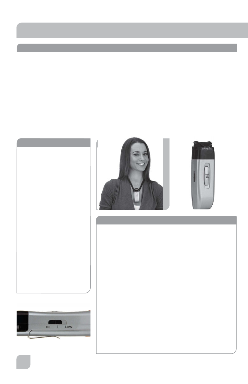
The infrared microphone/transmitter is comprised of a microphone input, signal processing
circuits and several emitting diodes that transmit the vocal signal to the sensor.
The microphone/transmitter can be the Sapphire or Handheld. The rechargeable batteries will
provide 6–8 hours of service per charge. Place the microphone/transmitter in the charger for
overnight charge and it will be ready for another day’s use.
The drop-in battery chargers are specifically designed to recharge lithium & NiMH batteries
at an optimum rate for maximum operating capacity and extended service life. Charger will
automatically start charging the batteries upon insertion and will shift to a maintenance
charge when batteries are fully charged.
features
•Elegant design
•Only 1.4 oz. including battery
•Long life “Lithium ion” bat-
tery
•Rechargeable via USB cable
to computer
•Battery level indicator – Back
light under power switch
•Momentary mute button,
backlight blinks in mute
mode
•Push “on/off ” power
•Channel “A” or “B” selectable
•Three level microphone
volume switch
•(HI, MID -3dB, LOW -6dB)
HI is normal
•Auxiliary input (3.5mm)
•Wear with a lanyard or slide
directly on neckline collar
(IRT-60) sapphire transmitter
The Sapphire’s vocal clarity is unsurpassed. Its
high level output is achieved by the unidirectional
(Cardioid) microphone and a unique free air
suspension system. With a built-in breath filter, the
Sapphire can function as a pass around hand mic.
The strategic alignment of the emitting diodes
assures reliable connectivity throughout the room
without static or drop out.
With a tap on the power button, the microphone
is muted for private conversation—tap again to
restore to normal operation. The auxiliary input
allows wireless playback of your iPod™ through the
Sapphire. A three position slide switch provides
selection of low, medium, or high microphone
sensitivity.
4
2
Page 11

features
•Condenser microphone
element
•Power “on/off ” switch
•Battery level indicator—
LED
•Channel “A” or “B” selectable
•10 high-power emitting
diodes
•Diodes at top and bottom
of handle for increased
Coverage (2 Top aimed
out, 6 Bottom 360°,
2 Bottom aimed down)
•360º IR radiation for assured connectivity
•Two “AA”, Duracell, rechargeable NiMH batteries
IRT-60 remote control features
1. Moving the priority switch Up/Down will control
the volume of the line inputs.
2. A momentary tap of the priority switch will
duck down the line inputs 15dB. The receiver front
panel power switch changes to a blinking PURPLE.
A second tap will restore line input back to normal.
3. Hold in priority switch for 4 seconds closes
the contact closure on the Security Alert output.
The receivers front panel power switch changes
to binking GREEN. Holding the button down for
another 4 sec. returns the contact to normal.
IRH-35 handheld transmitter
The Handheld Microphone Transmitter (IRH-
35) is most applicable for student use or direct
presentation. It has an “on/off” switch and a
battery level indicator LED; Green=useable charge,
Red=low battery. The transmitter has 10 emitting
diodes: 8 around the bottom of the handle, and 2
toward the top of the handle. The metal housing
provides low handling noise and insures durable
longevit y.
5
Page 12
Maxim III
owner’s manual
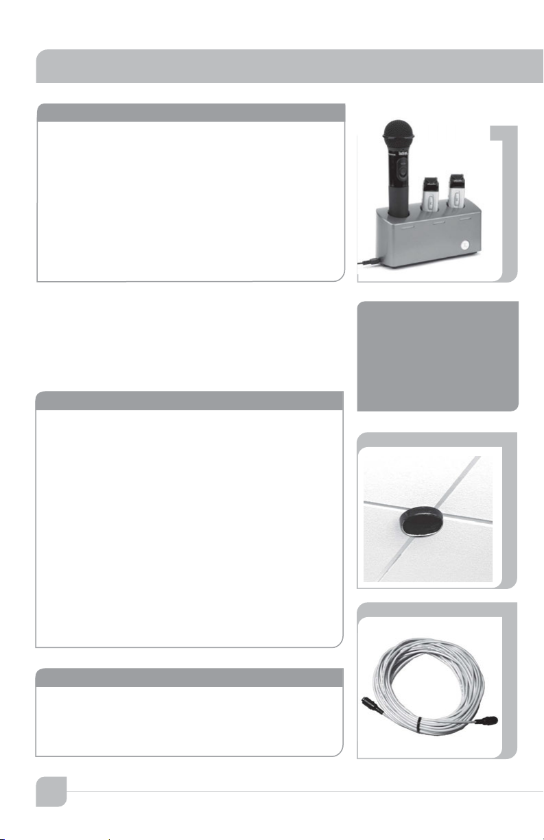
BRC-55 drop-in battery charger
This stylish desktop drop-in charging station makes
it convenient and easy to recharge both Sapphire
Pendant and Handheld Microphones. Charge one
IRH-35 handheld transmitter and up to two IRT-60
Sapphire transmitters simultaneously. Charging
indicator lights illuminate Red when charging, and
Green when fully charged. The “TL” logo illuminates
Blue when plugged in.
ICS-55 ceiling sensor
The ceiling sensor is the preferred infrared sensor
for optimum performance. This is the unit that
needs to be installed on the ceiling. It comes with
a mounting/support bracket and 50 feet of plenum
rated cable with RCA connector on each end. The
ideal location for the dome sensor would be in the
center of the ceiling. This will provide a clear signal
path for the IR transmission from the transmitter to
the dome sensor without obstruction. In addition,
you will have 360° coverage and will minimize
the transmission distance for more reliable
performance. It collects the infrared transmission
signal via 6 large detecting diodes.
power “on” LED
Green light indicates that
the sensor is receiving
power from the receiver.
sensor cable
A Cable connects the sensor to the receiver. The
cable is dual-shielded with a male RCA connector
on each end and is plenum rated.
6
Page 13
installation of ICS-55 ceiling sensor
ICS-55
ICS-55
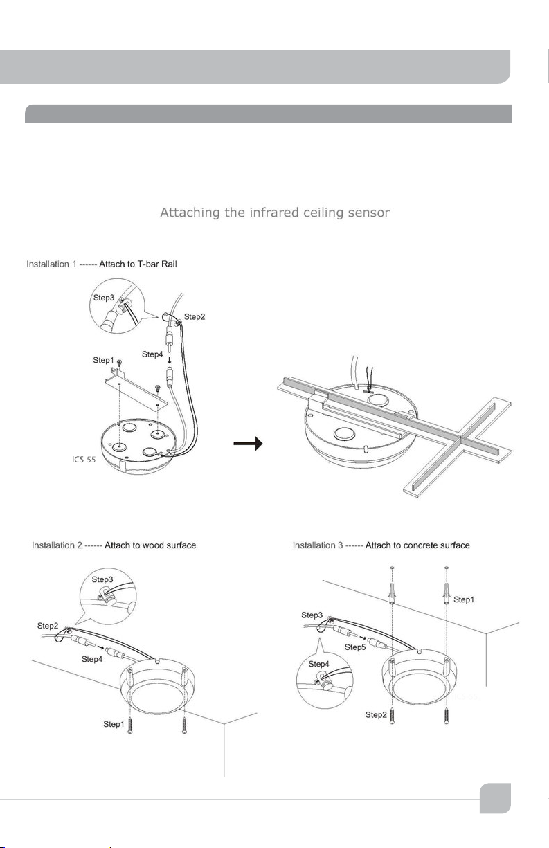
The ideal location for the ceiling sensor is in the center of the ceiling. This will provide a
clear signal path for the IR transmission from the transmitter to the dome sensor without
obstruction. In addition, you will have 360º coverage and will minimize the transmission
distance for more reliable performance.
7
Page 14
Maxim III
Front of Room
Listening Area
Front of Room
Ceiling Speakers
Ceiling Sensor
owner’s manual
installation of speakers
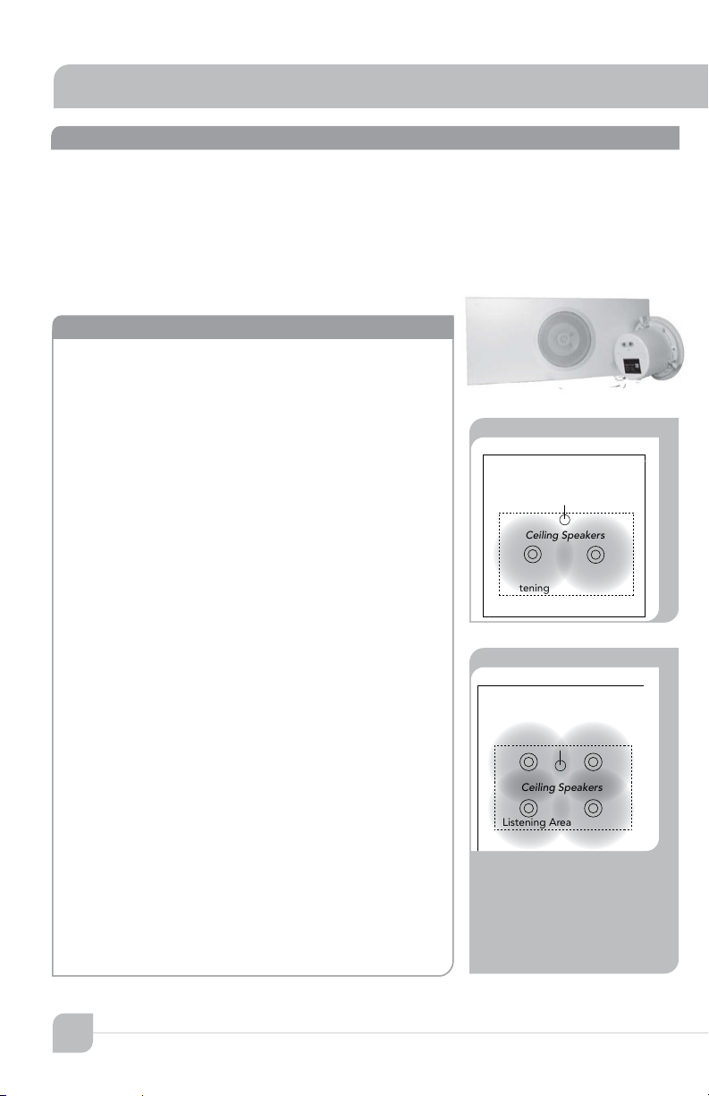
Two wall mount or ceiling speakers can be powered by the receiver/amplifier. It has two amplifiers
(25 watts ea.). One speaker will be connected to each amplifier.
Optional: Two additional speakers can be powered by the amplifier. Connect two speakers in
parallel. Then bring a cable from each pair to the amplifier. Connect one pair to each amplifier.
installing two SP-628 ceiling speakers
•Determine the listening area.
•Divide listening area into two quadrants
•Locate and identify the center most tile in each
quadrant
•Lay ceiling tile face down on clean flat surface
•Lay tile bridge on ceiling tile and center it
•Trace and cut the large hole using a keyhole or
drywall saw
•Strip the speaker cable ends, approx. ½"
•Route speaker wire from speaker opening to
amplifier
•Reinstall ceiling tile with tile bridge in place above
the hole
•Pull speaker cable back down through speaker
hole
•With a pointed tool or paper clip, lift up and
remove speaker grille
•Set speaker on top of ladder and connect speaker
cable connect
•Observe speaker polarity, connect Red wire to (+)
terminal and black wire to the (C) terminal
•With the mounting clamps folded back, position
speaker into speaker hole
•With a #2 Phillips screwdriver, tighten the quick
clamps
•Reinstall speaker grille and remove any soil or
fingerprints
•Repeat same for other speaker
Ceiling Sensor
Ceiling Speakers
Listening Area
Optional:
Two Additional Speakers
8
4
Page 15
Front of Room
Receiver
Amplifier
Ceiling Sensor
Wall Speakers
Front of Room
Receiver
Amplifier
Ceiling Sensor
Wall Speakers
Optional:
Two Additional Speakers
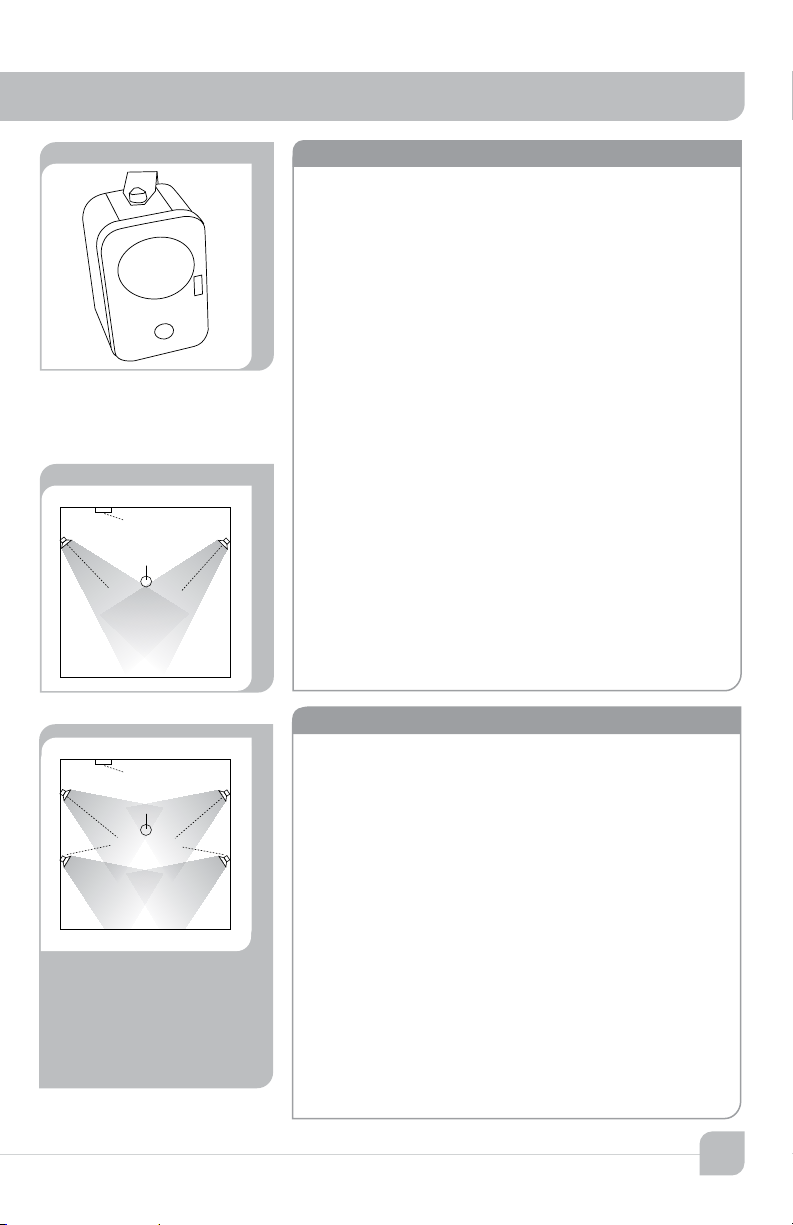
installing SP-2000 wall mount speakers
•First observe the shape of the room: ceiling height,
door locations, windows, mounting surface, and
seating area
•Ordinary installation would be to locate the
speakers on each side wall approximately even
with the front row of listeners
•Mount the speakers 6–7 feet above the floor
•Install the mounting brackets in the vertical (up/
down) orientation
•Mount brackets using the appropriate hardware
•Insert speaker with the tweeter in upper position
•Secure speaker in bracket with the hand fasteners
•Orient each speaker toward the center of that half
of the listening area
•Strip speaker cable ends ½” and connect to
speaker
•Observe speaker polarity: Connect (+) wire
(with printed writing) to (+) terminal and (-) wire
(unprinted & textured) to the (-) terminal
•Route speaker cable to the receiver/amplifier in a
safe, least visible, tidy manner
final connection of the system
With receiver/amplifier located, speaker and sensor
cables neatly routed, we are ready to complete the
installation.
•Cut the speaker wire to the appropriate length
•Strip about
wire.
3
/8” off the end of each speaker
•Twist the wire and if you have a soldering iron,
tin the wire ends
•Unplug the phoenix connector, insert (+) wire
(with printed writing) into either outside (+)
terminal. Plug the other (-) wire into center (-).
•Tighten set screws.
•Repeat for other pair and insert plug firmly into
speaker receptacle
•Plug power supply into AC outlet
79
Page 16
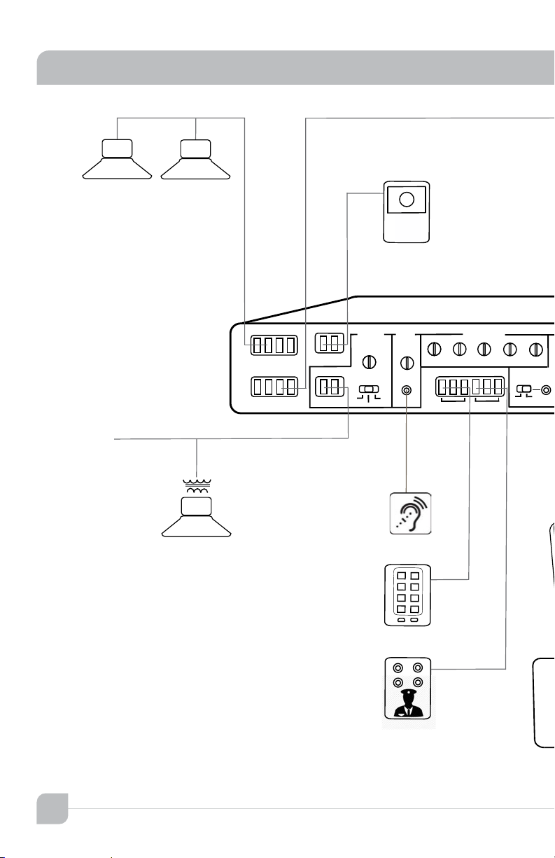
Maxim III
Maxim III rear view
INPUTS
COMPUTER
DVD
SENSOR
POWER
19V DC
3.4A MAX
EQUALIZER
SPEAKER OUTPUT
+
_
123
+
_
RS232
SECURITY ALERT
FIRE ALARM
AC/DC 5-24V
1KHZ
300
100
MIC
1 Tx
2 Gnd
3 Rx
COM
N/O
N/C
COMP/ANTI-HUM
4ohm load = 25watts/amp
10KHZ
3KHZ
ON
OFF
AUX
SENSITIVITY
ALS
PAGE INPUT OUTPUT
100V
70V
25V
+
_+_
owner’s manual
Ceiling Speakers
From
Page System
owner’s manual
Fire Alert
Panel
A
owner’s manual
B
10
Classroom
Paging Speaker
Assistive Listening
Device
RS-232 Wall Control
Panel
note
Secruity Alert
Panel
Page 17

system wiring
INPUTS
COMPUTER
DVD
SENSOR
POWER
19V DC
3.4A MAX
COMP/ANTI-HUM
OFF
5 VOLT
OUTPUT
Ceiling Sensor
Ceiling Speakers
Computer
Maxim III
CH A CH B
DVD COMPUTER
Drop-in Charger
DVD Player
AUX
Maxim III front view
MP3 Player
MP3
INPUT
Lesson Capture
LESSON
CAPTURE
OUTPUT
Infrared Transmitter
“Sapphire” IRT-60
Recorder
11
Page 18

Maxim III
transmitterowner’s manual
page over-ride/page pass through
The page over-ride feature allows you to connect the TeachLogic amplifier to
the school paging/intercom system for muting purposes. A simple connection
between the in-classroom paging speaker (typically 25v or 70v) and the
TeachLogic page input will mute all the inputs and pass the page to the speakers
connected to the TeachLogic amplifier
Unplug the 2 pin green Phoenix connector
Connect the speaker cable from the paging system to the 2 pin
Phoenix connector of the Page input
Reconnect the 2 pin green Phoenix connector
Determine the signal level of the paging system (25v, 70v, or 100v)
Set the slide switch to the appropriate speaker level setting
With the TeachLogic amplifier turned ON, send a page signal through
the page input
Adjust the page input SENSITIVITY control so that an incoming
page/intercom signal will override any audio (mics, dvd etc) plugged
into the TeachLogic amplifier.
In the event of a loss of AC power, the TeachLogic amplifier will continue to
pass the page on to 2 of the speaker connections as outlined on the following
diagram. Only the upper left and lower right speaker outputs will pass page
without power.
12
Page 19

fire alarm input
The 2 pin orange Phoenix connector labelled Fire Alarm, was designed to
provide an emergency mute of the TeachLogic amplifier. When interfaced to
the fire alarm relay contact output, all audio devices (microphones, dvd, etc.)
will turn SILENT. In the event of a fire, this will help to lower the overall decibel
levels and help students and staff hear the audible fire alarm tones/instruction
within the classroom. This feature only requires a 5-24 volt AC or DC source.
blank page
page pass through - fire alarm contacts
13
Page 20
Maxim III
transmitterowner’s manual
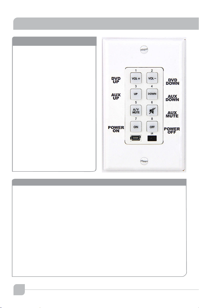
RS-232 features
The RS-232 feature allows the user to
remotely operate the line level media
inputs via a convenient wall panel
controller.
Audio levels very often need to
be adjusted when switching from
computer audio to DVD players and
other audio sources. Such operations
as level UP, DOWN and MUTE are
easily accomplished via a typical eight
button controller, as shown here. This
allows the receiver/amplifier to be
placed in an area or compartment
that is not easily accesssed by the
user. Codes that are required for this
setup are also available below or from
TeachLogic's website.
RS-232 codes
blank page
blank page
Baud Rate : 9600
Parity Bit : NONE
Data Bit : 8
Stop Bit : 1
TL COMMAND Functionstring HEX
POWER ON Power: ON 4c 69 6e 6b 78 3a 50 6f 77 65 72 3a 4f 4e
POWER OFF Power:OFF 4c 69 6e 6b 78 3a 50 6f 77 65 72 3a 4f 46 46
Gain DVD UP Gain:DVD :UP 4c 69 6e 6b 78 3a 47 61 69 6e 3a 41 55 58 3a 55 50
Gain DVD DOWN Gain: DVD:DOWN 4c 69 6e 6b 78 3a 47 61 69 6e 3a 41 55 58 3a 44 4f 57 4e
Gain DVD MUTE Gain:DVD :MUTE 4c 69 6e 6b 78 3a 47 61 69 6e 3a 41 55 58 3a 4d 55 54 45
Gain Computer UP Gain: Computer:UP 4c 69 6e 6 b 78 3a 47 61 69 6e 3a 44 56 44 3a 55 50
Gain Computer DOWN Gain :Computer:DOWN 4c 69 6e 6b 78 3a 47 61 69 6e 3a 44 56 44 3a 44 4f 57 4e
Gain Computer MUTE Gain: Comp uter:MUTE 4c 69 6e 6b 78 3a 47 61 69 6e 3a 44 56 4 4 3a 4d 55 54 45
14
Page 21
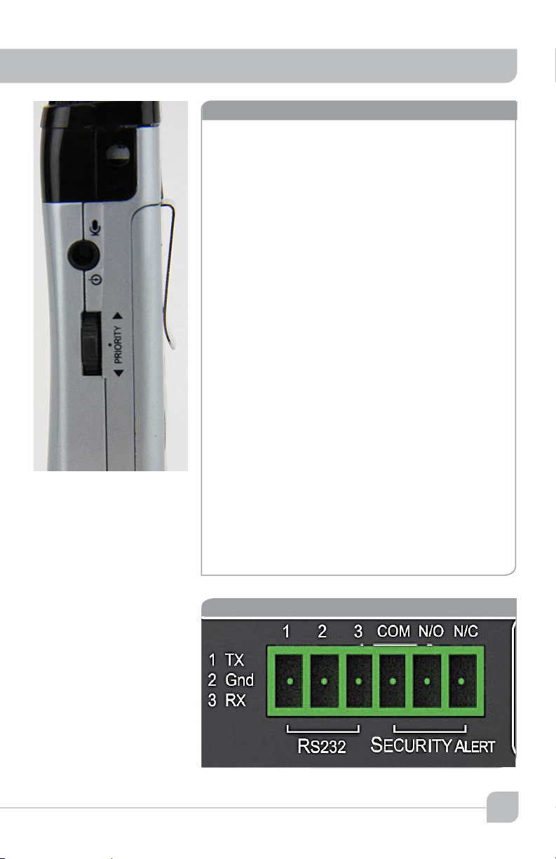
security alert features
The security Alert features allows the teacher/
presenter to send a silent wireless electronic
signal with a simple press of a button, in the
event of an in-classroom security incident. The
signal is easily generated by the teacher who is
wearing Sapphire wireless pendant microphone.
This same microphone transmitter which is used
for in-room amplification, has a special button
(labelled PRIORITY) on the side for initiating the
Security Alert. Simply holding down the button for
4 seconds, "closes" a contact closure on the rear
panel of the TeachLogic amplifier and sends the
Security Alert signal to the appropriate location
possibly the principal's or security monitoring
station. The front panel power switch on the
front of the amplifier will "blink" with a soft green
background.
To disengage from the Security Alert mode,
simply hold the side button for 4 seconds, and
the amplifier will return to its normal state with the
front panel power button illuminated with a solid
blue background.
The output is a three pin NO/NC contact closure
labeled Security Alert.
RE-232 and Security Alert contacts
15
Page 22

Maxim III
transmitterowner’s manual
operation of wireless microphone
Now that the system is installed and connected, we are ready to turn the system “ON” and test
its performance. The testing will be done using an IR transmitter (Sapphire or Handheld) to
confirm good connectivity and quality audio.
system operation
•Turn the Maxim III “ON”, Blue LED will light
•Confirm power to sensor, Green LED on edge of
sensor
•Set volume of Ch A volume control to mid scale
(12 o’clo ck )
•Using a Sapphire Transmitter microphone select
channel “A” (Mics are shipped in channel A)
• Sapphire: “A–B” switch, remove battery cover
on back, under battery.
• Handheld: Unscrew barrel and remove.
Note “A–B” switch on side of battery holder.
•Turn volume control on Sapphire transmitter to
"Hi" level. This is the normal setting.
•Switch transmitter “on”
•Observe power LED (Blue) - use fully charged
battery only
•Observe signal presence LED (Orange) on
receiver adjacent to “Mic” volume control
•Stand under or in front of a speaker
•Slowly adjust “Ch A” volume on Maxim III while
talking into microphone
•Adjust to desired listening level.
CAUTION: Beware of feedback
•Walk around the room while talking into
microphone to confirm good connectivity
16
Upon completion of performance test,
the installation is complete.
Page 23

troubleshooting
Problem Solution
System is turned
“on” but there is no
sound
System has power
but no sound
Voice is distorted
and/or signal dropout occurs
•Verify AC power; the Red
LED lights when turned
“on”
•
Check if system has
been unplugged
•
Check circuit breaker
•
Call maintenance for
assistance
•Turn “on” microphone/
transmitter
•Check for IR transmission,
Signal presence (Orange
LED)
•Check the Yellow LED in
the sensor
•If sensor LED is not lit
•
Sensor has been
disconnected
•
Power output to sensor
has failed (Receiver/
amplifier needs to be
replaced)
•Check the charge on your
batteries
•Verify power switch in
battery compartment is in
“Hi” position (Body-Pack
transmitter)
•Verify that the diodes on
transmitter or sensor are
not being covered
•Obstruction between
transmitter and sensor
contact
If your problem persists
and this guide has not
resolved the issue, call our
customer service department for additional assistance. (800) 588-0018
17
Page 24

Maxim III
transmitterowner’s manual
Maxim III (IMA-520) specs.
Receiver Input
Modulation
Reception Frequencies
Infrared Wavelength
Tone Signal
De-emphasis
Frequency Response
S/N Ratio
THD
Nominal Deviation
Maximum Deviation
External Sensor Input
Aux Inputs
Line Output
Equalization
Security Alert Output
RS-232
Fire Alarm Input
Power Output
Output Impedance
Output Connection
Power Supply
Dimensions
Weight
Enclosure
Infrared FM
FM Wide-band
Ch. A: 2.08 MHz, Ch. B: 2.54 MHz
850 nm
Ch. A: 32.768 KHz
50 µs
50 Hz, -13KHz, C 3dB
›65 dB
‹1% @1KHz
± 10 KHz
± 25 KHz
Two, R CA
Four line level inputs for DVD,
Computer, Aux and MP3
Switchable computer anti-hum circuit
Aux input (Microphone or Line level)
One Lesson Capture Output, 3.5mm
with Gain Controls, Front Panel
One ALS Output, 3.5mm with gain
control, Rear Panel
Five Band Digital ±12dB
N/O, N/C contact closures
Wall panel control of line input levels
AC or DC 5-24 volt
Two Am plifier s, 50 w att s total (R MS) ,
25 watts ea. (RMS)
4ohm min, per channel
One Phoenix Connector, ch A & B
19VDC /3.4A / 65W CE,CSA & UL
Listed
8 1/2" W x 1 3/4" H x 7 1/2" D
2 lb. 2oz.
Aluminum
power supply (AC-36) specs.
Typ e
Input Voltage
Output Voltage
Power Output
Regulated Switching Power Supply
100–240 volts AC, 47–63Hz
19 volts DC, 3.4A
65 watts Max.
18
Page 25

Sapphire transmitter (IRT-60) specs.
Transmitting Diodes
Operating Range
Battery Discharge Indicator
Blue
Purple
Red
Flashing Red
Battery Used
Battery Life
External Power Charger
Transmission Angle
User Controls
Power Switch (push)
Mute Switch (push)
Mic Switch (3 position)
Aux . Vol./Gain
Security Alert
External Aux. Input
Dimensions
Weight
Six
1,600 Ft ². 60 Ft. Line of Sight
Full
Medium
Low
Very Low Battery
Lithium-ion (3.7V / 620mAh)
Approx. 8-9 Hrs/Charge
DC +5V, Micro USB Connector
Conical
On/Off
On/Off momentary push
HI, MID -3dB, LOW -6dB
Increase, Decrease
5 second hold of priority button
3.5mm Line Level
3 5/8" H x 1¼" W x ¾" D
1.4 oz. Including battery
Handheld transmitter (IRH-35) specs.
2 Channel Switchable
Transmitting Diodes
Modulation
Pilotone Frequency
Peak Deviation
Operating Range
Power Switch (Slide)
Battery Charge Level (LED)
Battery Life
Dimensions
Weight
Field Switchable
Ten
FM Wide-Band
32.768 KHz
± 25KHz
1600 Ft². 60 Ft.
On/Off
Green (Useable Charge)
Red (Needs Charging)
Approx. 7 Hr./Charge
21/8" Dia. Head,
17/16" Dia. Body, 95/8" H
10.3 oz. w/ Batter y
drop-in battery charger (BRC-55) spec
Charging Port
Red LED
Green LED
Power Supply
Dimensions
Weight
2 Sapphire, i Handheld
Battery being charged
Battery fully charged
5 VDC, 1 Amp
7 3/4" L x 2 3/4" W x 3 3/4" H
1 lb. 12 oz.
19
Page 26

Maxim III
owner’s manual
five year limited warranty
TeachLogic IR products are guaranteed to be free
of defects in workmanship or material for a period
of five (5) years from date of original purchase,
subject to the following conditions:
1. Warranty excludes defects caused by normal
use and wear, any abuse, or failure to use the
product in accordance per instructions.
2. Warranty is void if damage occurred because
of misuse, or attempted repair or modification
by unauthorized personnel.
3. Warranty on batteries is for two (2) years.
4. Warranty does not extend to finish.
5. All warranty service will be provided by
TeachLogic or authorized service center
6. Warranty is made to the original purchaser and
may not be transferred to another user.
7. Warranty service rendered will be on a repair
or replacement basis, whichever TeachLogic
deems to be most prudent for customer
satisfaction and economic feasibility.
TeachLogic will only accept warranty shipments
accompanied by Return Authorization Number
previously assigned by TeachLogic personnel.
Advance warranty replacements will be made per
the discretion of TeachLogic personnel.
TeachLogic will pay return shipping cost on all
warranty repairs or replacements.
20
contact
TeachLogic, Inc.
Customer Service Dept.
1688 Ord Way
Oceanside, CA 92056
1
•800•588• 0018
sales @teachlogic.com
1•760•631•1283
www.teachlogic.com
8
Page 27

Page 28

1688 Ord Way
Oceanside, CA 92056
1•800•588• 0018
sales @teachlogic.com
1•760•631•1283
www.teachlogic.com
2
5/28 /14
 Loading...