

Page 1
Page 2

TABLE OF CONTENTS
Foreword ……………………………………………..…………. i
How the System Works ………………………………….……... ii
Features and Description of the Maxim System ……………….. 1
Front Panel ……………………………………………….. 1
Rear Panel ………………………………………………… 2
Infrared Dome Sensor (ICS-50) ………………………….……… 3
Drop-in Battery Charger ………………………………………… 3
BRC-30 ……………………………………………………. 3
BRC-101 and BRC-202 …………………………………… 3
Pendant Transmitter (IRT-89) ………….……………………...... 4
Body-Pack Transmitter (IRB-30) ……………………………….. 4
Plug-in Microphone (LM-300) ……………………………. 4
Ultra Lite Microphone (ULM-835) ……………………….. 4
Collar Microphone (CM-835) ……………………………... 4
Lapel Microphone (LP-835) ……………………………….. 4
Handheld Transmitter / Microphone (IRH-30) …………………... 5
Speakers …………………………………………………….......... 5
Ceiling Speaker (SP-628) ………………………………….. 5
Wallmount Speaker (SP-2000) …………………………….. 5
Prior to Installation ………………………………………………..6
Installation Procedure ……………………………………………. 7
Installation of Maxim ……………………………………… 7
Installation of Speakers ……………………………………. 8
Installation of Dome Sensor ………………………………...……10
Final Connection of System …………………………………….. 11
Operating the System ………………………………………….....12
Battery Charger Operation …………………………………….…13
BRC-30…………………………………………………….. 13
BRC-101 and BRC-202 …………………………………… 14
Final Check of System …………………………………………... 16
Trouble Shooting ……………………………………………...… 17
Specifications ……………………………………………………. 18
Page 3

FORWARD
Congratulations on the purchase of your new Maxim II Sound Field
System produced by TeachLogic. Be assured that the Maxim II meets
all specifications and was produced to very high quality control
standards. TeachLogic incorporates the latest state of the art
technology, employs the most advanced manufacturing methodology
and uses only premium quality components to assure many years of
reliable performance. We appreciate your confidence by selecting a
TeachLogic product and it is TeachLogic’s intent to support you in the
use of your system.
We hope you will take some time to review this manual to familiarize
yourself with the product features and its performance. The manual
will help guide you to gain maximum use and benefit of the Maxim II
sound field system.
The manual provides some basic explanation on the basic principles
of Infrared transmission and its benefits. To be followed up with
operator instruction and installation instruction. The manual will
conclude with maintenance procedures and trouble shooting analysis.
If you should encounter some unresolved issue, please contact
TeachLogic customer service department for further assistance.
Telephone Number: 800-588-0018
e-mail: teachlogic.com
Brian Van Waay , President
Page 4

How the System Works
A Brief Word About Infrared
Infrared is a light ray that is below the visible light spectrum, just like
the sound spectrum extends beyond your hearing ability. An example
of infrared transmission: is the remote control for your TV set. A beam
of infrared light is emitted by a Light Emitting Diode (LED) from the
remote control and it is detected by a receiving diode in your TV set.
When you push a certain command on your control, the internal
electronics causes the infrared light to flicker in a programmed
sequential pattern (called modulating the light beam). The modulated
infrared beam is detected by a receiving diode and is electronically
decoded. The decoded signal activates the circuitry to perform the
command function on the TV set.
So how does this apply to the infrared communication system you are
about to start using? The body-pack transmitter or handheld
microphone has several Light Emitting Diodes (LED) that emit
infrared light beams to the sensor located on the ceiling (the dark red
doom). Now when you talk into the microphone, the microphone
element modulates the light beam, causing it to flicker in sync with
your speech. The dome sensor detects that sequential signal and an
electronic signal is sent to the receiver inside the Maxim II
mixer/amplifier unit. The receiver decodes the signal from the sensor
and converts it into an electronic audio signal that is sent to the
amplifier. The amplifier magnifies the electronic signal which is sent
to the speakers. This causes speaker cone to move back and forth in
sync with your voice. The speaker replicates your voice and disperses
it so all can hear with ease.
The IR signal will bounce off walls, ceiling, floor, and be received
by the sensor, therefore; the transmitter does not need to be
pointed at the sensor. Resulting in total freedom of movement
throughout the room and hands free mobility. Noted feature,
infrared will not penetrate through a solid surface thus impeding
any transmission from going out of the room.
“What’s said in the room stays in the room”
Page 5
Features and Description of the Maxim II System
Mixer/amplifier (IMA-420)
is the nucleus of the classroom
sound field system. The pendant transmitter, body-pack transmitter
or handheld microphone transmitter: transmit the vocal signal via
infrared light to the dome sensor installed on the ceiling. The signal is
then sent via cable to the receiver input of the mixer/amplifier. The
signal is detected and then processed through the power amplifier to
the speakers.
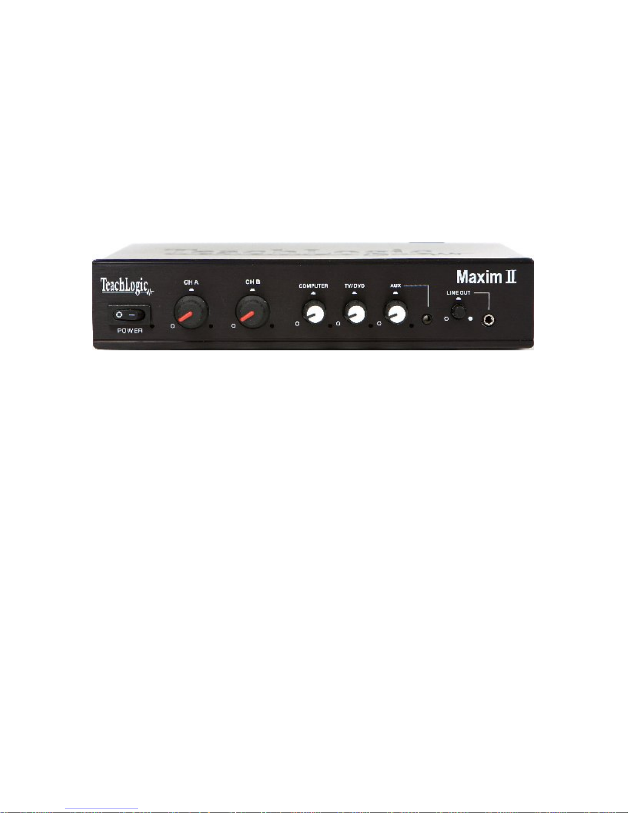
Front Panel _______________________________________________
Power Switch
with an associate red LED to indicate presence of
power.
Channel “A” & “B” wireless microphone volume controls.
IR Indictor, LED adjacent to each control knob will light “Green”
when a transmitter on that channel is turned “on”, validating an IR
transmission signal is being received.
Auxiliary Input Controls for adjusting the volume of each media
input source; COMPUTER, TV/DVD, AUX.
will light “Green” when an audio signal is present on that input.
Front Panel Auxiliary Input for “ipod” or similar device (3.5mm). The
rear auxiliary input will disengage when the front input is in use and
the “AUX” control will adjust the volume.
Line Out is for an “Assistive Listening System”, Personal FM system
or could used as a record output. Gain control adjusts the output
signal to match the input of the auxiliary devise.
Page 6
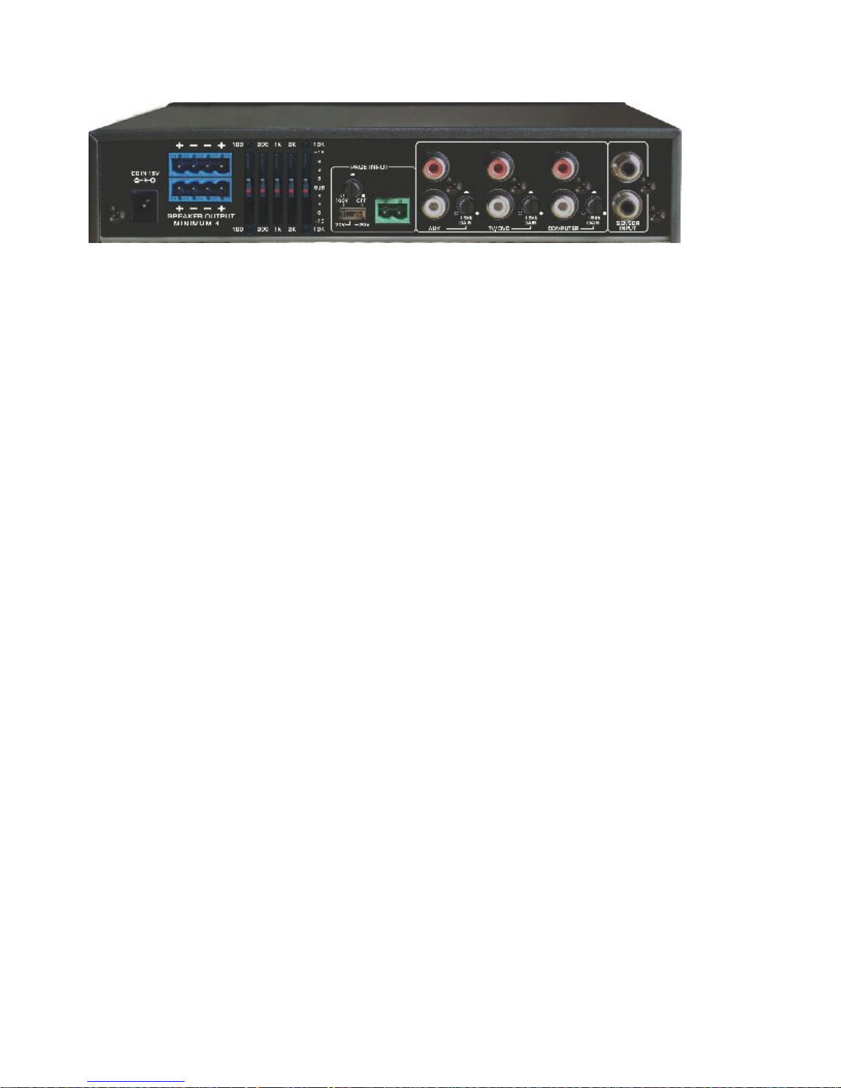
Rear Panel _________________________________________________
Power Input
is 15 volts DC, 2.8 A.
Two Amplifier Outputs each terminated by a dual latching Phoenix
connector (facilitating connecting two speakers in parallel).
Power output of each amplifier:
16 watt (RMS) into 4
12 watt (RMS) into 8
load or
load
Five-band Graphic Equalizer provides the installer capability to
compensate for acoustical variance and maximum vocal clarity. A
protective cover prevents maladjustment once the system has been
professionally calibrated for optimum performance.
Page Over-ride allows the school announcements to pass through the
classroom sound system. The announcing system (speaker level 25,
70, or 100 volt, selectable) is connected via the two-pin phoenix
connector and the volume is adjusted with the gain control. The page
will mute all the inputs during the page and restore to previous levels
after page is completed.
Auxiliary Audio Inputs (stereo RCA) for various media sources such
as: Computer, DVD, Projector, VCR, or other. The normal sensitivity
of these inputs is -25 dB but the sensitivity of each can be increased
with the sensitivity gain control adjacent to the input (up to 15dB).
Sensor Inputs (RCA) for powering the sensor and receiving IR
transmission signal. Two sensor inputs allow installation of an
additional sensor for odd shaped or large rooms requiring additional
coverage. Normally only one sensor is required.
Page 7
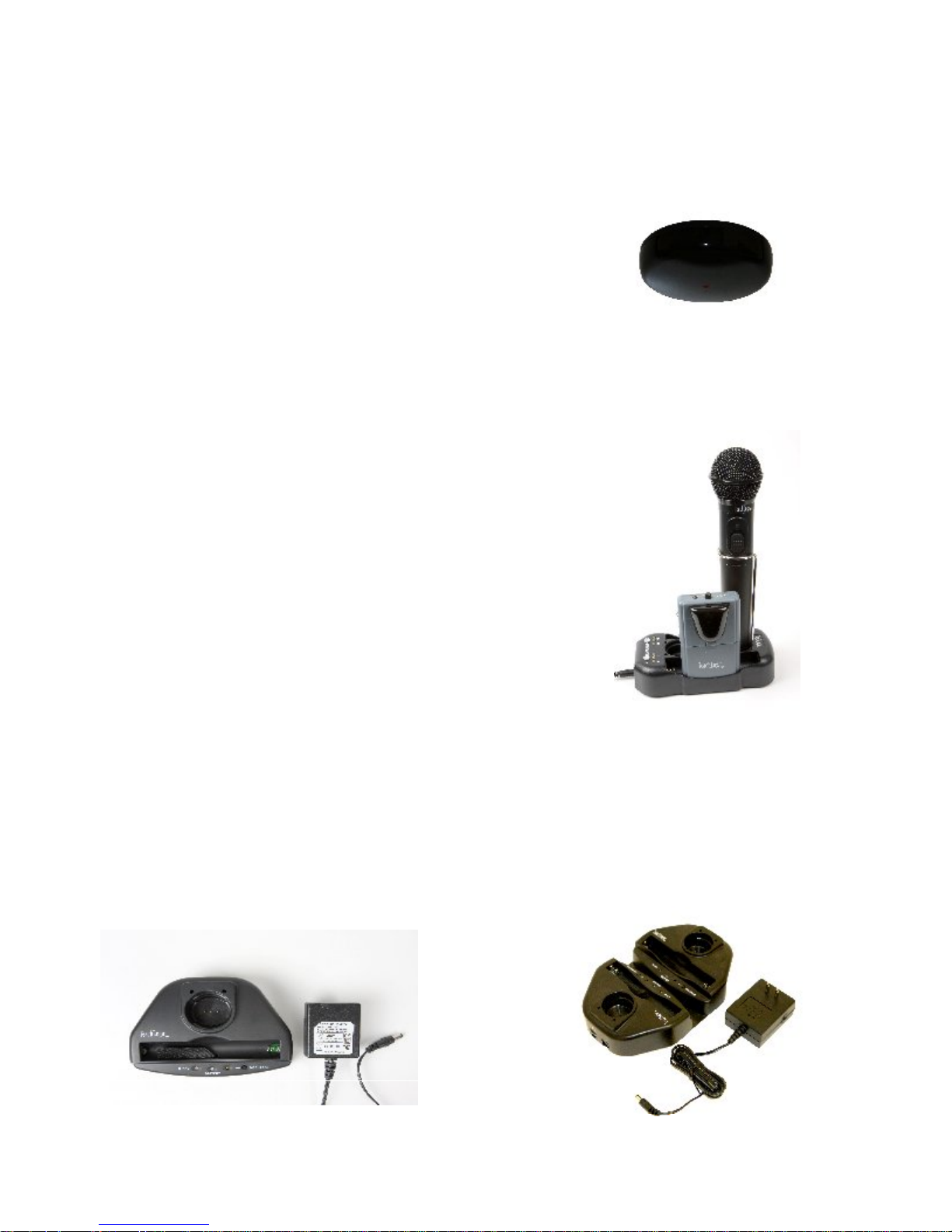
Infrared Dome Sensor (ICS-50) is installed on the ceiling. It is
the component that collects the infrared transmission signal via 30
detecting diodes. The sensor sends the information to the
mixer/amplifier and via a shielded cable.
Drop-in Battery Chargers
The battery chargers were specifically designed to recharge NiMH
batteries at an optimum rate to maximize their usage. All the chargers
feature a recycle function, which is used to recycle the battery to
restore its charge capacity and extend its service life.
BRC-30 charger recharges the (IRB-30) body-
pack transmitter and
microphone. You merely place the body-pack
and handheld microphone in their respective
slot. Connection will automatically be made
and charging will commence. Charger will
automatically control the charge rate and
maintain the full charge.
(IRH-30) handheld
BRC-101 and BRC-202 drop-in chargers are for the handheld (IRH-
30) and pendant transmitter (IRT-89). The single slot (BRC-101) can
charge either. The dual (BRC-202) can charge both simultaneously.
Both chargers have a front tray to insert two “AA” batteries for
recharging. Both chargers will automatically control the charge rate
and maintain a full charge.
Page 8
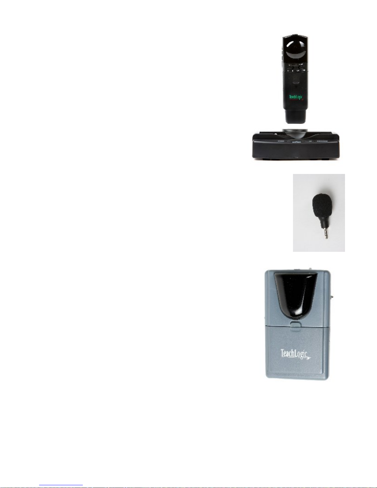
Pendant Transmitter (IRT-89) with a built-in
microphone. The pendant transmitter is the
smallest transmitter and is usually worn
around the neck. Two lanyards are provided:
one with a safety breakaway clasp and a longer
adjustable over the head style. The
transmitting diodes are in the top portion and
the rechargeable NiMH batteries are housed
below. The power switch is accompanied by a
battery level LED (Green=Useable, Red=Needs
Charge). The A-B switch selects the
transmission channel. The pendant can be
placed in either the BRC-101 or BRC-202
charger.
An optional Plug-in microphone (LM-300) can be plugged
into the top of the pendant for enhanced performance.
Although the built-in microphone gives satisfactory
performance, the plug-in microphone is a unidirectional
element resulting in better vocal quality and much more
gain (more volume) before feedback.
Body-Pack Transmitter (IRB-30), usually worn
on the waistband, is the component that
transmits the IR signal to the sensor. The IRB30 has 10 emitting diodes on its front panel and
is powered by two rechargeable NiMH batteries.
Controls include a power “on/off” switch and a
mic gain control. Battery level indicator LED:
Green = useable charge, Red = low battery.
It is required to plug in an external microphone.
There are several optional microphones available
and they plug into the top of the IRB-30. The
IRB-30 is equipped with belt clip for waist
attachment.
Caution: The body-pack cannot be placed in pocket and the red window
cannot be obstructed, those are the emitting diodes.
Page 9

Plug-in Microphone (LM-300) is a small capsule size microphone
that plugs directly into the top of the IRB-30 body-pack. A lanyard
cord is provided to accommodate wearing the body-pack transmitter
around the neck and utilizing it as a pendant microphone. A
windscreen is included to prevent breath pops when used in close
proximity to the mouth.
Ultra Lite Microphone (ULM-835) is a miniature boom style
microphone supported by a wire around the left ear. The mic boom
extends along side of face and has a unidirectional microphone with
windscreen. The small ring on the boom prevents perspiration from
entering the mic element. Aside from comfort,
the boom style mic renders the best
performance in terms of sound quality and is
not prone to feedback.
Caution: The boom can be formed to fit but it is
not a flexible boom, do not bend back and
forth. IT WILL BREAK !
Collar Microphone (CM-838) is a flexible rod that is formed around
the neck. The end with the microphone and windscreen is then
contoured up toward the mouth. The cord
exits the rod in the center in back, out of the
way, and is plugged into the body-pack. The
collar mic utilizes a unidirectional mic
element to minimize feedback and renders
quality voice reproduction.
Lapel Microphone (LP-835) is a small
capsule microphone with a spring clip for securing on to a clothing
edge. The lapel microphone is well suited for out of sight application.
However; as a result of the microphone being farther away from the
mouth, more gain is required for adequate
volume. An omni-directional microphone
element is used to pick up from all directions.
These two factors make the lapel microphone
most prone to feedback when used near or
under a speaker.
Page 10
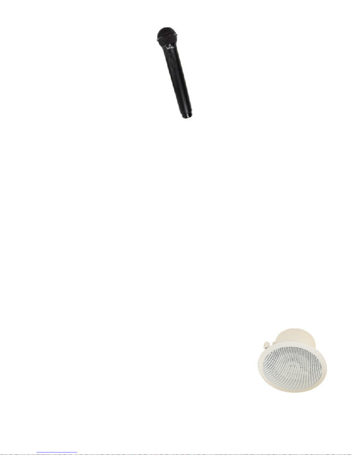
Handheld Microphone Transmitter (IRH-30) is most applicable for
student use or direct presentation. It has an “on/off” switch and a
battery level indicator LED; Green=useable charge, Red=low battery.
The transmitter has 10 emitting diodes around the bottom of the
handle. The metal housing provides low handling noise and insures
durable longevity.
Speakers:
Ceiling Speaker (SP-628)
is an extended frequency range 6” coaxial speaker housed in a metal back can sealed to the trim ring
to form an infinite baffle enclosure. A screw terminal strip
provides the external speaker connection. The speakers are
equipped with three quick mount clamps for easy mounting into
a blind hole. The speakers are supplied with a tile bridge for
support above the ceiling tile. Plenum rated cable is provided for
connecting the speakers to the amplifier.
Specification: SP-628 speaker is ETL plenum
rated and meets the UL-2043 plenum code.
Page 11
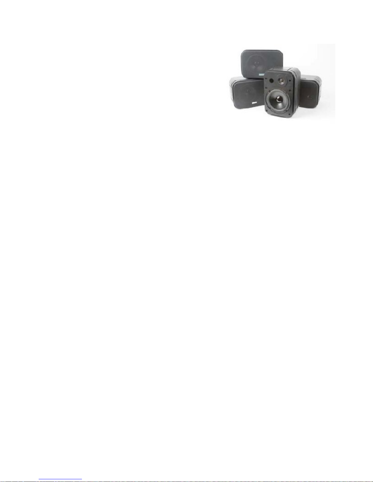
Wallmount Speaker (SP-2000) is
a two-way speaker housed in a
port tuned enclosure with a 6”
woofer and a 1” H.F. domed
tweeter. Euro-block connectors
provide the speaker connection.
Brackets are included for wall
mounting. Heavy-duty speaker
wire is provided for connecting the
speakers to the amplifier.
PRIOR TO INSTALLATION
Be sure to observe all safety precautions
Wear goggles when using power tools.
Observe all safety guidelines when using ladders
Do not install your system near water or heat sources
Wear proper work clothing and sturdy shoes
Clean all components with a dry cloth
Use Teachlogic accessories only
Protect all cables from abrasion, sharp edges, and install in
a tidy manner
The following Tools/Supplies required for Installation
Safety Goggles
Power Drill Motor & Drills
Phillip #2 Screw Driver
Level & Tape Measure
Side Cutter & Scissor
Hammer
Staple Gun & Staples
Plastic Cable (zip) Ties
Raceway & Screws (If exposed wiring is required)
Aviation Metal Cutters
Ladder
Keyhole or Drywall Saw
Electrical Tape
Twine or Light Weight Pull Rope
Page 12

INSTALLATION INSTRUCTION FOR THE MAXIM II SYSTEM
Organize and Plan Your Installation
Upon arrival to the jobsite, observe the following criteria:
Observe the type of ceiling to determine your method of
installation of the speakers
Roughly layout the location of each speaker
For installation of wallmount speakers, determine the
mounting location.
Where will the Maxim II (Receiver/Amplifier) be installed
How will the Maxim II be mounted
What will be the best routing of the speaker wires
Where are the Auxiliary Audio Sources located and how will
they be Interfaced with the sound system
Determine the central location of the ceiling for installation of
the dome sensor and routing of the sensor cable to the Maxim
II
Installation Procedure
Installation of the Maxim II
Placement of the Maxim II mixer/amplifier is usually dictated by:
what other equipment will be integrated with the sound system,
and how it will be mounted. Location of the electrical AC power
outlet and the routing of the speaker and sensor cables. Cushion
pads are installed for free stance installation.
Installing the Maxim II under or above a shelf
Use the SM – 700 shelf mount kit
Mount the two tabs on the sides of the amplifier using the
threaded mounting holes and the threaded screws
provided.
The tabs can be mounted oriented inward or outward
With the tabs mounted, hold the amplifier in position and
mark the mounting holes
Drill mounting holes in support structure in accordance
with mounting hardware being used.
With tabs oriented outward, install the Maxim II onto
support
Page 13

With tabs oriented inward, remove the tabs and install
them on the support.
Insert and install the amplifier between the mounted tabs
Installing the Maxim II in an electronic equipment rack
Use the RM – 400 rack mount kit.
Mount the tabs on the side of the amplifier
Install the Maxim II in the rack at desired location
Installation of Speakers
The Maxim II can accommodate four (8Ώ) speakers. You will
connect two speakers in parallel and connect to one amplifier. Do
the same for the other two speakers. This will distribute 8 watt to
each speaker. Four speakers will be adequate to distribute sound
evenly throughout a classroom of approximately 2500 sq. ft.
When installing ceiling speakers in a dropped ceiling, you need to
consider will the room always be arranged in the same seating
arrangement or be moved about randomly?
For a room with permanent seating arrangement:
Designate the listening area and divide the area into four
quadrants. Then install one speaker in the center of each
quadrant.
For a room with random seating arrangement:
The whole room becomes the listening area. Begin by splitting
the room into four quadrants and skew away from areas known
not to be listening areas. Relay out the area and divide into four
quadrants and install one speaker in center of each quadrant.
Smaller rooms may only require two speakers. Two speaker
installation, locate the speakers in the center of the listening area
(front to back) and equidistant side to side of the listening area.
Install one speaker in the center of each half quadrant.
Installing the SP – 628 ceiling speaker
Locate and identify the speaker locations in the ceiling grid
With clean hands, remove the ceiling tile from the ceiling
grid
Lay ceiling tile face down on clean flat surface
Center the large hole of the tile bridge on the ceiling tile
Page 14

Trace and cut the speaker hole using a keyhole or drywall
saw
With the ceiling tile removed, measure the distance to the
next speaker and cut a speaker cable appropriate length.
Strip the speaker cable ends approximately ¾”
String the cut speaker cable from speaker location to next
speaker location.
Reinstall the ceiling tile with the tile bridge located above
the speaker hole.
With a pointed tool, remove the speaker grille.
Pull the speaker cable back through the speaker hole and
connect speaker cable to speaker
o Caution: Observe polarity, connect Red wire to (+)
terminal and other wire to the “C” terminal
Remove the speaker grille using a paper clip
Insert speaker into speaker hole
Hold in place and tighten the three quick clamps with a #2
phillips screw driver.
Reinstall speaker grille.
Remove any soil and fingerprints
Repeat above steps with the following additions:
Measure distance from speaker to amplifier
Cut and strip speaker wire.
Advance the wire from speaker to amplifier
Twist the two speaker cables together (Red to Red) and
Black to Black.
Connect the Red pair to the (+) terminal and Black to (C).
Installing the SP-2000 Wall Mount Speakers
First observe the shape of the room, ceiling height, door
locations, windows, mounting surfaces and seating area. In
a rectangular or square room, you would locate the two
wall speakers (one on each side) approximately even with
the front row listeners. Locate the other pair approximately
mid-way to the rear of the listening area.
The speakers should be mounted vertically about 5-6 feet
above the floor. Using the most appropriate fastener,
mount the speaker brackets onto the wall.
Page 15

Insert the speaker in the bracket and secure with the hand
screws
Orient the speakers toward the center of the listening area
and pointed mid way toward the rear.
Strip speaker cable ends ¾” and connect to speaker
o Caution: Observe polarity, connect Red wire to (+) Red
terminal and Black wire to Black (-) terminal
Route the speaker cable to the Maxim II; observing safe,
unsightly, least visible, and tidy route
Remove any soil, fingerprints and debris.
Installation of the Dome Sensor
The preferred location for the dome sensor would be in the
center (side to side) and favored forward towards the front. This
will provide a clear and direct IR transmission path from
transmitter to sensor without any obstruction or interference.
The 360º reception pattern provides coverage through the entire
room.
.
Locate the center ceiling tile or one forward of it and mark
the approximate location for the sensor.
Remove the designated ceiling tile, measure and mark the
center location for the sensor.
Drill or cut a ¾” hole through the tile.
Place the mounting bracket across the center hole and drill
two holes, one on each side nearest to the center hole for
the mounting screws.
Route the sensor cable through the bracket & tile hole and
connect to sensor.
Mount the sensor with the two #6 sheet metal screws, ¾”
long.
Advance the roll of sensor cable toward its exit point going
to the amplifier.
Reinstall the ceiling tile.
Remove any soil, fingerprints and debris.
Installing the Dome Sensor on a Hard Surface
Observe the notches and the grooved lines on bracket
Page 16

Hold bracket with the two center grooved lines facing up
Bend the side straps at the grooved lines up toward you,
little less than 90º
Bend the end straps at grooved lines in the opposite
direction
You should now have bracket that is modified U shaped
with side mounting tabs
Mount the bracket to the sensor with the short screws
provided
Connect cable to the sensor
Locate the center of the ceiling and mount the sensor to the
ceiling with appropriate fasteners
Route the sensor cable either up through the ceiling if
feasible or surface mount using a raceway or use of self
adhesive wire tie pads & wire ties
Route to the Maxim II amplifier
If surface mounting, observe straight taut runs in a tidy
manner
Remove any soil, fingerprints and debris
Final Connection of the System
With all the two speaker wires and sensor cable neatly routed to the
amplifier, we are ready to complete the installation.
Connecting the Dome Sensor
Plug the sensor cable into either of the sensor input jacks
(RCA)
Coil up the excess cable (if applicable) and place it out of
the way and view
Connect the auxiliary audio sources
The auxiliary input jacks are dual RCA phono jacks. They
are labeled on the back corresponding to the volume
control on the front panel. Connect each source using a
shielded cable with RCA connectors.
You can use stereo cables because the two channels will be
summed internally so both channels will be passed through
as a combined monaural signal.
Page 17

Connecting the Speakers
Cut the speaker wires to the proper length.
Split the cable and strip approximately ⅜ - ½” off each
wire.
Twist the stranded wire and if you have a soldering iron
available, it is a good practice to tin the wire ends.
It is important to observe speaker polarity (note speaker
diagram on back panel of Maxim II).
Unplug the phoenix block connector and insert the RED
wire to either outside screw terminal. Insert other wire
into the next slot. Tighten the setscrew.
Do same with the other speaker cable.
Operating the System
Now that the system has been installed, we are ready to turn the
system “on” and test its operation. We’ll assume the inputs will
include a wireless body-pack transmitter, handheld microphone
and at least one auxiliary audio source.
Turn Maxim II “on”, power switch on left side
Red LED will light to indicate power
Set the Ch. A and Ch. B controls to 12 0’clock
Test using a microphone
Using the body-pack transmitter with a microphone plugged in
or a handheld, the procedure will be the same.
Verify that the batteries are fully charged for optimum
performance.
Set the body-pack gain control to minimum, fully CCW
Turn “on” the body-pack via the slide switch on the side of
the body-pack.
Observe the Green LED on top of body-pack transmitter
(Good charge on battery).
Observe the LED next to Ch. A volume control indicating IR
signal being received when the body-pack is turned “on”
If the Ch. B LED turns “on”, remove the battery cover of the
body-pack and slide the channel selector switch to Ch. A.
Locate yourself directly under a speaker.
Page 18

While speaking into the microphone, slowly adjust the
volume using the gain control on top of the body-pack.
When you begin to hear a ringing sound (initial indication
of feedback) reduce gain to stable sound.
While talking, walk around the perimeter of the room to
verify 100% reception of the signal.
Upon completion of the test, put the belt-pack in the
charger for recharging
Handheld Microphone Transmitter and its Features
Turn “on” the microphone with slide switch and observe,
Green LED
Observe the LED next to Ch. B volume control indicating IR
signal being received when the microphone is turned “on”
If the Ch. A LED turns “on”, unscrew the bottom half of the
handheld and slide the channel selector switch to Ch. B.
Speak into the microphone and adjust the volume using
Ch. B control on Maxim II.
While talking, walk around the perimeter of the room to
verify 100% reception of the signal.
Upon completion of test, put the microphone in the
charger for recharging
Drop-in Battery Charger BRC-30
The BRC-30 charger is for recharging the batteries in the Body-Pack
transmitter (IRB-30) or Handheld transmitter (IRH-30). Insert either
transmitter into the fitted receptacle. Charging will commence
automatically.
USE RECHARGEABLE NiMH BATTERIES ONLY
The battery charger is a rather sophisticated charger. It will
charge the NiMH batteries at an optimum charge rate, maintain
a full charge, and can recycle the batteries for extended battery
service life.
Plug the power adapter Plug into an AC outlet
Plug DC cable into charger
Page 19

Place handheld microphone and/or body-pack transmitter
into their appropriate slot
A Red LED will light indicating unit is charging
At full charge, the LED will change to Green.
An audible buzzer will buzz an alert when the batteries are
fully charged. The buzzer can be turned “on or off” with the
slide switch located on the bottom of the charger. (The
charger is normally shipped with the switch in the “off”
position).
To recycle the rechargeable batteries, push and hold the
black button for 3-5 seconds. A YELLOW LED will light
indicating the batteries are being discharged. When the
batteries are exhausted, the charger will reverse and
charge the batteries to full capacity. Recycling the batteries
on a monthly or bi-monthly basis will extend the service
life of the batteries.
If non-rechargeable batteries are placed in the charger, it
will sense the non-rechargeable batteries and will not
charge them. The red LED will commence blinking
continuously.
Caution: Do not attempt to recharge non-rechargeable batteries such
as Alkaline or similar. The charger will usually sense the fallacy,
however; there are certain conditions that are not detectable depending
on the condition of the batteries.
Attempting to charge non-rechargeable batteries can damage the
transmitter, charger, cause batteries to leak, over heat and create a
danger for fire.
BRC-101 and BRC-202 can recharge the batteries in the Pendant transmitter
(IRT-89) or Handheld transmitter (IRH-30). Insert either transmitter into the
fitted stand receptacle. Charging will commence automatically. Two “AA”
batteries can also be inserted into the front tray for charging.
Page 20

USE RECHARGEABLE NiMH BATTERIES ONLY
Charging Batteries in “Stand” Receptacle:
Plug power supply into an AC outlet and insert plug into charger.
Insert transmitter, either Pendant or Handheld into receptacle, the
STAND” Red and Green LED’s will blink once, indicating charger is
“
operational.
“STAND” LED will start Blinking Red, indicating batteries are being
charged. (3 – 4 Hours)
“STAND” LED will change to “Green” when batteries are fully charged.
Charging Batteries in Front Tray:
Insert two “AA” batteries in tray (observe polarity)
Center “BATTERY” LED will start Blinking Red, indicating batteries
being charged. (3 – 4 Hours)
“BATTERY” LED will change to “Green” when batteries are fully
charged.
Discharging Batteries:
Discharge batteries to rejuvenate and extend service life.
Remove batteries from transmitter and insert in front tray.
Push “DISCHARGE” button.
“Amber” LED will light, indicating batteries being discharged.
Upon exhaustion and recharging, center “BATTERY” LED will glow
“Green”, completing the cycle.
Recommend recycling every 30 – 60 days. Will increase service life.
Trouble Shooting:
Battery service per charge has shortened. Attempt discharging,
sometimes that will rejuvenate the batteries and restore some
capacity. Otherwise, it is an indication the batteries have reached
their service life and need to be replaced.
Useful Life Expectancy: 1½
- 2 years.
If you should observe: overheating of batteries or charger. Unplug
charger immediately and either notify your dealer or TeachLogic.
Page 21

Do not leave batteries in discharged state for extended periods of
time.
Do not subject batteries to high temperature.
For additional information on battery care, consult your system
manual or
Congratulations, this completes the installation and it is now
time to show the user how to use the system
Turn “on” the Maxim II via the power switch
Plug a microphone into the body-pack and set the gain
control at zero (max. CCW)
Turn the body-pack transmitter “on” via slide switch on the
side of the transmitter
Observe the Green LED on the body-pack indicating a
useable charge on the batteries
Observe the Red LED near the Ch. A volume control, it
indicates a signal being received from the body-pack
Turn Ch. A volume to approximately mid scale (12 o’clock)
While talking into the microphone, slowly turn the gain
control CW until you’ve achieved a comfortable listening
level
Using the Handheld microphone, turn it “on”, the Green
LED will light and the Red LED adjacent to the Ch. B
control will light indicating signal presence from the
handheld microphone
Slowly turn the Ch. B volume control CW until the desired
listening level is achieved
Now venture around the room while alternately talking into
each microphone. Observe no interruption or drop outs
while moving about
Connect an auxiliary audio source (computer, Video
projector, DVD player, VCR, ipod) using a shielded cable
with appropriate connectors, plugged into the designated
RCA jack
Page 22

Turn the audio source “on” and engage its operation.
Adjust the volume level of each auxiliary input to the
desired listening level.
Computers and remote control projectors often have very
low output. If more volume is required, adjust the
respective input sensitivity control on back panel. Adjust to
desired volume level.
Once all the auxiliary inputs have been verified and
adjusted, the system is ready for full operation
Trouble Shooting
System is turned “on” but there is no sound
o Verify AC power; the Red LED lights when turned
“on”
Check if system has been unplugged
Check circuit breaker
Call maintenance for assistance
o System has power but no sound
Verify charged batteries in body-pack
Turn “on” body-pack and check for signal
Check the Green LED in the center of the dome
If sensor LED is not lit, the dome sensor has
If LED is lit but there is no sound
If either condition cannot be resolved, call
presence (Green LED below volume control)
sensor
either been disconnected or the power for the
sensor has failed
TeachLogic customer service.
When using the microphone, the voice is distorted and/or
signal drop out occurs
o Check the charge on your batteries
Recycle the batteries by placing the transmitter
The yellow LED will light and the charger will
in the charger and press the black button and
hold for 3-5 seconds
automatically discharge the batteries and then
Page 23

recharge to full charge. (Time required 4 -6
hours)
Recheck the system after cycling the batteries
If the problem persists, replace the batteries
When using the body-pack transmitter and microphone,
the voice is intermittent and/or has a static like sound
o Try moving the cable back and forth at the plug-in
connector or where it is connected to the
microphone
o If the noise and intermittent connection is associated
with the movement of the cable, the cable connection
needs to be repaired
If your problem persists and this guide has not resolved the
issue, call our customer service department for additional
assistance. (800) 588-0018
Page 24

General Specifications:
Amplifier / Receiver (IMA-420)
Amplifier and Mixer:
Two Power Amplifier: 12 watt ea. into 8 load
16 watt ea. into 4 load
32 watt max (RMS)l
Frequency Response 40Hz – 18KHz, 3 dB
S/N Ratio >65dB
THD < 1%@1KHz
(3) Aux Inputs Line Level w/+ 15dB gain
Front Panel Input Line Level (3.5mm)
Front Panel Output Line Level w/ gain for AIS
Line Output Line Level (Pre-fader)
Equalizer 5 Band, 12dB
Page Override/Pass Through
Speaker Level Input
25v, 70v, 100v Selectable
Gain Control
Power Supply 15v DC, 2.8A, 42 watt
CE, CSA, and UL Listed
Infrared Receiver Section
Two IR Receivers: Channel A: 2.08 MHz
Channel B: 2.54 MHz
Receiver Sensitivity: 6µV for 60 dB S/N
Modulation FM wide-band
Nominal Deviation 10KHz
Maxmim Deviation 25KHz
Receiving Range: 2500 Sq. Ft
60 Ft. Line of Sight
External Sensor Inputs: Two
Dimensions: 9” W x 1.75” H x 8’ D
Weight 3.5 lbs. (1.6 Kg) (including Pwr. Supply)
IRB – 30 BODY-PACK TRANSMITTER
Transmission Carrier Infrared Ray
Carrier Frequency Channel A: 2.08 MHz
(field switchable) Channel B: 2.54 MHz
Modulation FM wide-band
Pilotone Frequency 32.768KHZ
IR Wavelength 850 nm
Peak Deviation ±25KHz
No. of Emitting Diodes Ten
Compander Circuit Yes
Pre-emphasis 50µS
IR Emitter Location Built-in
Transmission Angle 360º
IR Power Output High - Low Selectable
Page 25

Current Consumption Hi - 400ma Lo - 330 ma
Range Hi about 30 yds.
Lo about 20 yds
Microphone Input 3.5mm jack, Lo-z
Battery Two Rechargeable NiMH,
1.2v / 2650mAH
Battery Life Approximately 7 Hours
Dimensions 4⅜” H x 2⅝” W x ¾” D
Weight 4.8 oz. (with batteries)
IRH – 30 HANDHELD TRANSMITTER
Transmission Carrier Infrared Ray
Carrier Frequency Channel A: 2.08 MHz
(switchable) Channel B: 2.54 MHz
Modulation FM wide-band
Pilotone Frequency 32.768KHZ
IR Wavelength 850 nm
Peak Deviation ±25KHz
No. of Emitting Diodes Ten
Compander Circuit Yes
Pre-emphasis 50µS
IR Emitter Location Built-in
Transmission Angle 360º
Current Consumption 330ma
Microphone Element Unidirectional, Dynamic
Battery Two Rechargeable NiMH, 1.2v / 2650mAh
Battery Life Approximately 6 Hours
Housing Aluminum
Dimensions 10” L x 1½” Dia.
Weight 11.4 oz. (with batteries)
BRC - 30 DROP- IN BATTERY CHARGER
Charging Slots Two Handheld, Slots A & C
Charging Mode Switching
Charging Current 1700ma ±10%
Discharge Rate 350ma
Red LED Indicator Batteries being Charged
Green LED Indicator Batteries Fully Charged
Yellow LED Indicator Batteries being Discharged
Audible Alert Intermittent Buzz -
Recycle Button (Grey) Press for Full Discharge and Auto
Auto Switching Switch from Discharge to Charge Mode
Two Body-Pack, Slots B & D
Batteries Fully Charged
Recharge
Page 26

Charging Time 1.5 - 3Hr.
Power Supply 12VDC / 1.5A (Fuse protected)
Dimensions 6½” L x 3⅜” W x 1½” H
Weight 12.2 oz.
ICS - 50 CEILING DOME SENSOR
Operating Frequency 2MHz to 2.6 MHZ
Number of IR LED’s 30 Radial Spaced
Interconnection 50Ft. Plenum Rated Shielded Cable, RCA
Connectors
Operating Range 50 – 60 Feet Line of Sight
Reception Area 2500 Ft.²
Power Indicator Green LED
Reception Angle 360º Semi-Spherical Coverage
Dimensions 5” D x 1½” H
Weight 1.2 lbs.(with 50’ cable)
 Loading...